Article

On the Energy Efficiency of Millimeter Wave Massive MIMO Based on Hybrid Architecture

by
Peerapong Uthansakul
* and
Arfat Ahmad Khan
School of Telecommunication Engineering, Suranaree University of Technology, Nakhon Ratchasima 30000, Thailand
*
Author to whom correspondence should be addressed.
Energies 2019, 12(11), 2227; https://doi.org/10.3390/en12112227
Submission received: 1 May 2019 / Revised: 22 May 2019 / Accepted: 6 June 2019 / Published: 11 June 2019

Abstract

:
Millimeter Wave (mmWave) Massive Multiple Input Multiple Output (MIMO) has been a promising candidate for the current and next generation of cellular networks. The hybrid analogue/digital precoding will be a crucial ingredient in the mmWave cellular systems to reduce the number of Radio Frequency (RF) chains along with the corresponding energy and power consumption of the systems. In this paper, we aim to improve the energy efficiency of mmWave Massive MIMO by using a combination of high dimension analogue precoder and low dimension digital precoder. The spectral efficiency and the corresponding transmitted and consumed power of the mmWave Massive MIMO is formulated by taking all the consumed power from the transmitting side to receiving end into account. We propose the Power Controlled Energy Maximization (PCEM) algorithm in this paper, and the proposed algorithm works by controlling the transmission power to balance the improved radiated energy efficiency and the increased power consumption for a given number of transceiver chains. The simulation and analytical results show that the proposed algorithm performs better than the reference algorithms by maximizing the overall energy efficiency of the system without much complexity.

1. Introduction

The internet data traffic has been exponentially growing at a staggering rate, and the last couple of decades have witnessed the ever increasing demand for data rates, which in turn led to the congestion in the lower bands of electromagnetic spectrum [1,2,3]. Although a lot of spectrum sharing techniques have been proposed in order to overcome this congestion like the advanced channel coding [4], spread spectral techniques [5], cognitive radio communication [6], and the Massive Multiple Input and Multiple Output (MIMO) technologies [7], and even these techniques have somehow overcome the congestion problem, but they are not enough due to the ongoing and increasing gap between the supply and demand of data rate. This situation has attracted researchers to explore the millimeter Wave mmWave frequency band [8]. The integration of the Massive MIMO system with mmWave can be a fascinating approach to address this situation, and to support the huge traffic load of current and future 5G networks [9,10]. The Massive MIMO brings to the theory of large antenna array with hundreds of antennae serving a comparatively less number of users [11,12,13], whereas the mmWave frequencies allow the dense packing of antenna elements due to the small wavelength of mmWave frequencies [14,15,16,17].
In conventional low frequency systems, the base station requires Channel State Information (CSI) to precode and decode the transmitted and the received signal, but CSI acquisition in the mmWave systems is very different due to the huge path loss, fading and the distortion loses. Signal processing in mmWave system possesses a set of non-trivial constraints [18]. Furthermore, the expensive and high power consumption of mmWave systems cannot afford the separate dedicated Radio Frequency (RF) for each transmitting signal as compared to the fully digital baseband systems, where each transmitting antenna possess a separate dedicated RF chain [19,20]. This problem was addressed in [21,22,23], where the authors propose the analogue precoding by using the mesh of phase shifters [24,25]. The above-mentioned proposed techniques come out to be handy in terms of power consumption, but these techniques perform poorly compared to conventional digital baseband systems.
Recently, hybrid precoding has been a source of attraction for the researchers where precoding is implemented by using the combination of high dimensional analogue precoder and low dimensional digital precoder [26]. The hybrid precoding was introduced in [27,28], by dividing the precoding in the analogue and digital domains, where the authors assume that the CSI is available at the base station, and proposes the hybrid approach for the limited number of communication streams. In [29,30,31], the authors propose the hybrid approach for mmWave systems, and conclude that maximizing the spectral efficiency of the system is equivalent to the minimization of the Euclidean distance between the fully digital and hybrid precoders.
The above-mentioned researches focus on the maximization of the system’s spectral efficiency, but the power consumption of the system increased due to the addition of analogue precoder, which requires additional power to operate the network of phase shifters and combiners. Adding the consumed power results in the overall reduction in energy efficiency of the system. Therefore, the mmWave system’s energy efficiency needs to be addressed because the energy and power related pollution of the communication industry has become vital economical and societal concerns. In [32,33,34,35], the authors discuss the energy efficiency of the mmWave systems’ transceiver, but they do not correctly model the power consumption of the mmWave system and their algorithms don’t focus on maximizing energy efficiency for the mmWave systems, rather they work by maximizing the system’s spectral efficiency. Motivated by the above researches, the authors in [36] propose the hybrid algorithm which works by maximizing the overall energy efficiency of the system, but the authors have not correctly modeled the power consumption of the mmWave systems, and the proposed algorithm is very complex due to its dependency on the number of input streams. The mmWave communication systems’ energy efficiency can also be improved by controlling the beam width in order to allow more than one user to share a single RF chain, and results in the reduction of the consumed power of the system [37].
In this article, we focus on the energy efficient design of the mmWave Massive MIMO based on the hybrid approach. We formulate the spectral efficiency of Massive MIMO by using the hybrid precoding. The precoder of the Massive MIMO is designed by using the combination of the high dimension analogue precoder and low dimension digital percoder. Contrary to existing research, the power consumption of the Massive MIMO for the mmWave system is formulated by taking all the power consumption from the transmitting side to the receiving end into account. Furthermore, we propose the Power Controlled Energy Maximization (PCEM) algorithm to maximize the energy efficiency of mmWave Massive MIMO. Contrary to the existing algorithm, the proposed algorithm maximizes the overall objective function of energy efficiency by taking all the constraint into account. The simulation results compare the performance of the proposed algorithm with respect to reference algorithms, where it can be seen that the proposed algorithm converges near to the fully digital precoder without much complexity. The contribution of this article is summarized as follows:
  • We formulate and derive the spectral efficiency of mmWave Massive MIMO by using the hybrid precoding.
  • The realistic model of the circuit power consumption is derived and used for the formulation and computation of energy efficiency in this article.
  • The hybrid precoders and decoders are designed by taking the unit-modulus constraint and all the system constraint into account.
  • We propose the PCEM algorithm to optimize the energy efficiency by taking all the constraint into account.
  • The comparison is presented between the proposed and reference algorithms and the complexity of the proposed algorithm is computed to highlight the significance of the proposed algorithm.
The rest of this article is organized as follows. We present the system and channel models in Section 2 and Section 3, respectively. The hybrid precoders and decoders are designed in Section 4, and the power consumption of mmWave Massive MIMO is computed in Section 5. In Section 6, we propose the PCEM algorithm and optimize the energy efficiency. The simulation results are discussed in Section 7. We conclude in Section 8, where we summarize all the discussions.
The notations adopted throughout the paper are listed as follows: ( . ) 1 , ( . ) H and ( . ) T represents the inverse, Hermitian and transpose operator respectively, E [ . ] means the expectation operation, l o g 2 ( x ) denotes the logarithm of x to base 2, . F represents the frobenius norm, | . | represents the modulus operator, t r a c e [ . ] represents the trace operator, SVD ( . ) represents the Singular Vector Decomposition, d d p ( . ) represents the first order derivate with respect to p , Z + represents the positive integer, e ( . ) represents the exponential operator, f 1 ( . ) represents the inverse of the function, W ( . ) represents the Lambert Omega function, and O ( . ) represents the lambda big O notation.

2. System Model

Consider the mmWave Massive MIMO where the M number of antennae are equipped with the base station and communicating s = [ s 1 , s 2 , , s K ] data streams with the K number of user terminals. The base station is equipped with s < N t < < M RF chains, and the user terminals are equipped with s < N r < < K RF chains in order to reduce the hardware complexity and maintaining the effectiveness among the end users. The number of data streams is constraint as s < min { N t , N r } . In this paper, we used the hybrid approach by equipping the Base station with a M × N t high dimension analog precoder V A R F and N t × s low dimension digital precoder V D B B as can be seen in Figure 1. Similarly, the end users are equipped with a K × N r high dimension analog decoder W A R F and N r × s low dimension digital decoder W D B B . The downlink of the Massive MIMO was considered in this paper. As it can be seen in Figure 1, the transmitted signal s passes through the analogue and digital precoder then the transmitted signal can be written as:
A = V A R F V D B B s
The signal received y k at the k th user terminal can be written as:
y k = p G k V A R F , k V D B B , k s + p i = 1 , i k K G i V A R F , i V D B B , i s i + n
where G is the mmWave channel matrix and it is modeled in the next section. The first term in the above equation is the desired signal at the kth user terminal, whereas the second term is the interference term among the user terminals. n is the Additive White Gaussian Noise (AWGN) with zero mean and the unity variance.
Theorem 1.
The interference term can be neglected in the Equation (1) because the mmWave channel between two users i and j becomes zero under the scenario of Massive MIMO when M K + 1 , i.e.,
l i m M G i G j H M = 0
See Proof of Theorem 1 in Appendix A.
Therefore, Equation (1) can be written as:
y k = p G k V A R F , k V D B B , k s k + n
In order to retrieve the k th signal, the user terminal will multiply the received signal with the Hermitian of decoding matrix:
y k = p W A R F , k H W D B B , k H G k V A R F , k V D B B , k s k + W A R F , k H W D B B , k H n
The Signal to Noise Ratio (SNR) of the k th user terminal can be written as:
S N R k = p | W A R F , k H W D B B , k H G k V A R F , k V D B B , k | 2 W A R F , k H W D B B , k H F 2
S N R k = p | W A R F , k H W D B B , k H G k V A R F , k V D B B , k | 2 ( W A R F , k H W D B B , k H W A R F , k W D B B , k )
The achievable rate of the k th user terminal can be written as:
R k = l o g 2 ( 1 + S N R k ) = l o g 2 ( 1 + p | W A R F , k H W D B B , k H G k V A R F , k V D B B , k | 2 ( W A R F , k H W D B B , k H W A R F , k W D B B , k ) )
The corresponding spectral efficiency for the K number of users can be written as:
R K = K ( 1 T t o t K U ) l o g 2 ( 1 + p | W A R F , k H W D B B , k H G k V A R F , k V D B B , k | 2 ( W A R F , k H W D B B , k H W A R F , k W D B B , k ) )
where, the factor ( 1 T t o t K U ) accounts for the overhead of pilot, and T t o t , U represents the total pilot length and the coherence block respectively.

3. Millimeter Wave Channel Modeling

Two kinds of channel model are widely used. In the first model, the signals from two different antennae are considered uncorrelated by assuming that the transmitting antennae at the base stations are widely apart like the i.i.d Rayleigh fading model. In the mmWave channel, the antennae cannot be assumed uncorrelated due to the denser deployment of the large number of base station antennae. In this paper, we assume the Uniform Linear Array (ULA) at the base station and the mmWave channel can be written as [38]:
G = M × K N p l = 1 N p a l a K ( ϕ l K ) a M ( ϕ l M ) H
where a l represents the path loss coefficient of the lth ray, ( ϕ l K ) and ( ϕ l M ) represents the azimuthal angles of departure and arrival respectively. The azimuthal angles of departure and arrival are uniformly distributed from 0 to 2 π . Furthermore, the a K ( ϕ l K ) and a M ( ϕ l M ) represents the corresponding array response at the angle of departure and arrival. The array response of the M antenna array can be written as:
a ( ϕ ) = 1 M [ 1 , e j k d sin ( ϕ ) , , e j k d ( M 1 ) sin ( ϕ ) ]
where j = 1 , k = 2 π λ , and λ , d represents the wavelength and inter-distances among the antenna elements.

4. Modeling of the Hybrid Precoders and Decoders

In this section, we model the hybrid precoders and decoders. An obvious way to cast the problem of designing the hybrid precoders is a Euclidian least square fit:
min V V A R F V D B B F 2
where
V A R F = [ V A R F 1 . . . 0 0 V A R F 2 . . . . . . . 0 V A R F K ] V D B B = [ V D B B 1 . . . 0 0 V D B B 2 . . . . . . . 0 V D B B K ]
The challenges of solving the problem in Equation (5) are as follows:
  • The low complexity algorithm is required to solve the (5) during each transmission time;
  • All the non- zero entries of V A R F have the constraint of unit modulus, i.e., i , j   | V A R F ( i , j ) | = 1 ;
  • It is difficult to find the solution due to the constraint of unit modulus and the product of V D B B with V A R F ;
  • Therefore, we need to simplify Equation (5) to get rid of the products of V D B B with V A R F .
As we know
| A | F = ( A A H )
Therefore, Equation (5) can be simplified as:
V V A R F V D B B F 2 = t r a c e [ ( V V A R F V D B B ) ( V V A R F V D B B ) H ]
= t r a c e [ ( V V A R F V D B B ) ( ( V H V A R F H V D B B H ) ) ]
= t r a c e [ V V H V V A R F H V D B B H V H V A R F V D B B + V A R F V D B B V A R F H V D B B H ]
As all the columns of V D B B and V are mutually orthogonal to mitigate the inter user interferences, then:
V D B B V D B B H = I
Therefore, Equation (6) can be written as:
= t r a c e [ V V H V V A R F H V D B B H V H V A R F V D B B + V A R F V A R F H ]
= t r a c e [ V V H . I V V A R F H V D B B H V H V A R F V D B B + V A R F V A R F H ]
= t r a c e [ V V H V D B B V D B B H V V A R F H V D B B H V H V A R F V D B B + V A R F V A R F H ]
V V A R F V D B B F 2 = V V D B B H V A R F F 2
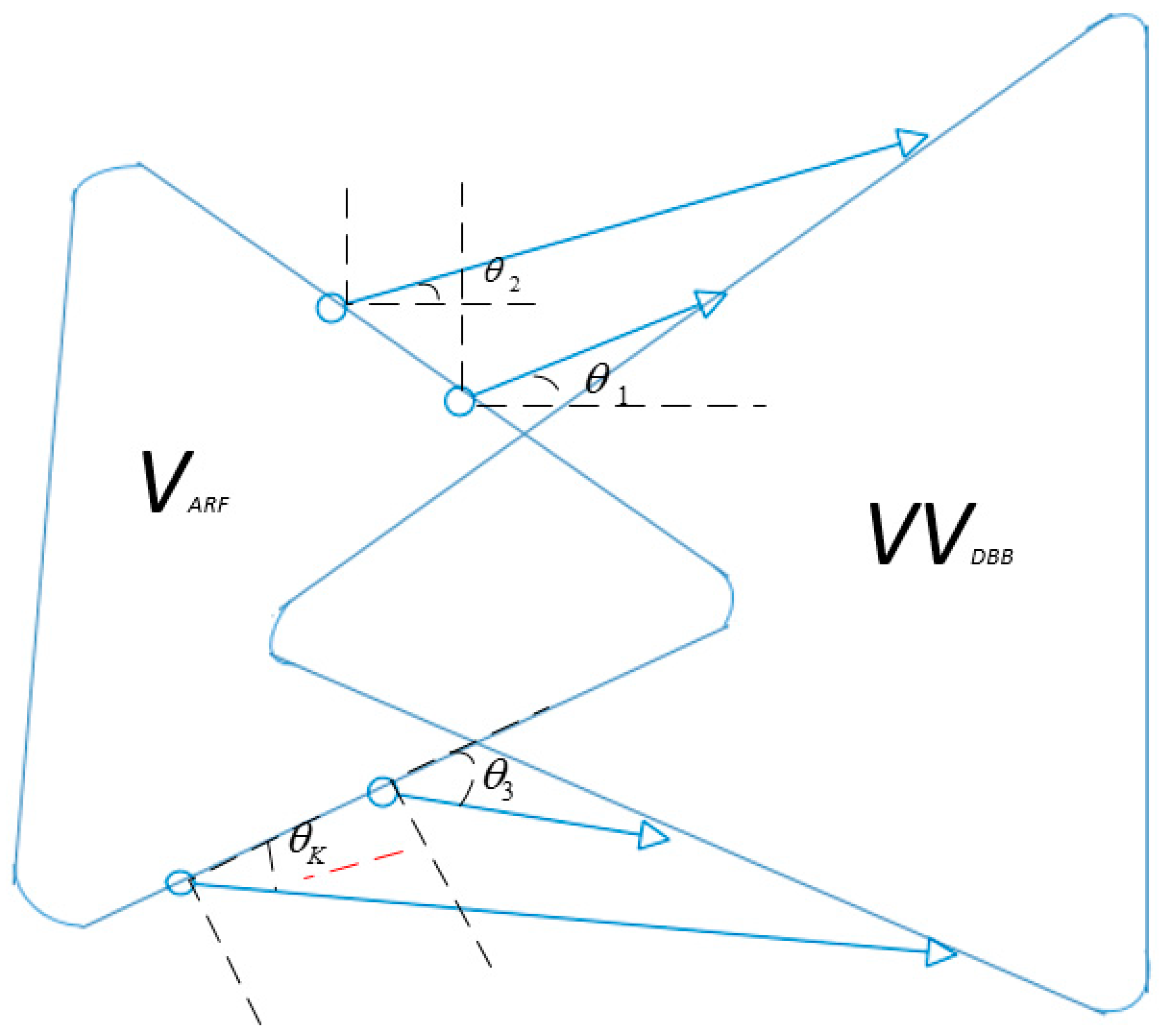
Following the simplification, the solution of Equation (7) can be computed by determining the Euclidean projection of V V D B B H on V A R F as demonstrated in Figure 2:
θ ( V V D B B H ) = θ ( V A R F )
Following the computation of analogue precoder V A R F , the product of V V D B B H can be decomposed into the Singular Vector Decomposition (SVD):
SVD ( V V A R F H ) = U V 1
and the corresponding digital precoder V D B B can be computed as:
V D B B = N s V 1 U H V A R F 2

5. Modeling of the Power Consumption

In this section, we model the power consumption of Massive MIMO. The total power consumption P T P C can be composed as an additive summation of the transmitted power P t p with all the consumed power P c p in the circuitry of Massive MIMO, i.e.,
P T P C = P t p + P c p
where, the overall consumed power P c p depends upon the fixed power P F x , power consumption of each transceiver chain P T C , power loss during the analogue precoding, compensation power P C L , and the coding and decoding power P c o / d e , respectively, and it can be written as:
P c p = P F x + P T C + P A R F + P C L + P c o / d e
The total transmitted power can be written as:
P t p = B α 2 p K V A R F V D B B F 2 η E { γ ( x ) 1 }
where B α 2 is the total noise power, η is the efficiency of the power amplifier γ ( x ) 1 represents the inverse channel attenuation.
Theorem 2.
The expected value of the inverse channel attenuation γ ( x ) 1 by using the polar coordinates can be written as:
E { γ ( x ) 1 } = d max i α + 2 d min i α + 2 ( 1 + α 2 ) × ( d max i 2 d min i 2 )
See Proof of Theorem 2 in Appendix B.
By using Theorem 2, Equation (13) can be written as:
P t p = B α 2 p K V A R F V D B B F 2 η × d max i α + 2 d min i α + 2 ( 1 + α 2 ) × ( d max i 2 d min i 2 )
The power consumption of each RF chain at the base station and end users can be written as:
P R F = P f i l + P m i x + P o c
where P f i l , P m i x , and P o c represents the power consumption during the process of filtering, mixing and frequency matching of the signals. As it can be seen in Figure 1, the base station and end users are equipped with N t and N r transceiver chains, respectively. Thus, the overall transceiver power consumption P T C can be computed as:
P T C = N t P R F + N r P R F
The power consumption of analogue precoder P A R F depends upon the power consumption of phase splitter P s , shifters P p s and the combiners P c , respectively, and it can be written as:
P A R F = M P s P p s P c N t
Similarly, the corresponding power loses of base station are compensated at the end users by using the Low Noise Amplifiers (LNA), and it can be written as:
P C L = P L N A ( K N r + K )
The power consumption during the coding P c and decoding P d of the signal P c o / d e depends upon the corresponding achievable rates, and it can be written as:
P c o / d e = R K ( P c + P d )
The total power consumptions by using the Equations (11)–(20) can be written as:
P T P C = B α 2 p K V A R F V D B B F 2 η × d max i α + 2 d min i α + 2 ( 1 + α 2 ) × ( d max i 2 d min i 2 ) + N t P R F + N r P R F + + M P s P p s P c N t + P L N A ( K N r + K ) + R K ( P c + P d )

6. Proposed Algorithm and the Optimization of Energy Efficiency

In this section, we describe the proposed PCEM algorithm along with optimizing the Energy Efficiency E E . The energy efficiency of the Massive MIMO is the ratio of the overall system throughput with the total consumed and transmitted power, i.e.,
E E = T h r o u g h p u t T o t a l   P o w e r = B × R K P T P C
E E = B K ( 1 T t o t K U ) l o g 2 ( 1 + p | W A R F , k H W D B B , k H G k V A R F , k V D B B , k | 2 ( W A R F , k H W D B B , k H W A R F , k W D B B , k ) ) B α 2 p K V A R F V D B B F 2 η × d max i α + 2 d min i α + 2 ( 1 + α 2 ) × ( d max i 2 d min i 2 ) + N t P R F + N r P R F + + M P s P p s P c N t + P L N A ( K N r + K ) + R K ( P c + P d )
We need to optimize the energy efficiency, and the optimization problem of energy efficiency can be interpreted as:
Constraint   to   max ( E E ) M > Z + ,   K > Z + K < M ,   p > 0   | V A R F | = 1 , | W A R F | = 1
The unit modulus constraint of the hybrid precoder and decoder have already been taken into account during modeling of the hybrid precoder and decoder in Section 4. Consider the following substitutions to simplify the expression of energy efficiency.
Let:
a 1 = K ( 1 T t o t K U ) ,   a 2 = | W A R F , k H W D B B , k H G k V A R F , k V D B B , k | 2 ( W A R F , k H W D B B , k H W A R F , k W D B B , k ) a 3 = B α 2 K V A R F V D B B F 2 η × d max i α + 2 d min i α + 2 ( 1 + α 2 ) × ( d max i 2 d min i 2 ) ,   a 4 = N t P R F + N r P R F + M P s P p s P c N t + P L N A ( K N r + K ) , a 5 = ( P c + P d )
Thus, Equation (22) can be simplified as:
E E = a 1 × l o g 2 ( 1 + p a 2 ) a 3 p + a 4 + a 5 × l o g 2 ( 1 + p a 2 )
The energy efficiency in terms of the transmitted power can be rewritten as:
E E ( p ) = a 1 × l o g 2 ( 1 + p a 2 ) a 3 p + a 4 + a 5 × l o g 2 ( 1 + p a 2 )
and, the corresponding optimization problem of energy efficiency maximization can be written as:
p = max ( E E ( p ) ) M > Z + ,   K > Z + K < M ,   p > 0   | V A R F | = 1 , | W A R F | = 1
Thus, the corresponding transmitted power which results into the maximization of energy efficiency can be computed by differentiating the energy efficiency with respect to p and equating the corresponding expression to zero, i.e.,
d ( E E ( p ) ) d p = d d p ( a 1 × l o g 2 ( 1 + p a 2 ) a 3 p + a 4 + a 5 × l o g 2 ( 1 + p a 2 ) )
d ( E E ( p ) ) d p = d d p ( ( a 3 p + a 4 + a 5 × l o g 2 ( 1 + p a 2 ) ) d d p ( a 1 × l o g 2 ( 1 + p a 2 ) ) ( a 1 × l o g 2 ( 1 + p a 2 ) ) × d d p ( a 3 p + a 4 + a 5 × l o g 2 ( 1 + p a 2 ) ) ( a 3 p + a 4 + a 5 × l o g 2 ( 1 + p a 2 ) ) 2 )
d ( E E ( p ) ) d p = d d p ( ( a 3 p + a 4 + a 5 × l o g 2 ( 1 + p a 2 ) ) ( a 1 a 2 ( 1 + p a 2 ) 1 ) ( a 1 × l o g 2 ( 1 + p a 2 ) ) × ( a 3 + a 5 a 2 1 + p a 2 ) ( a 3 p + a 4 + a 5 × l o g 2 ( 1 + p a 2 ) ) 2 )
d ( E E ( p ) ) d p = ( a 1 1 + p a 2 [ ( a 3 p + a 4 + a 5 × l o g 2 ( 1 + p a 2 ) ) a 2 [ ( l o g 2 ( 1 + p a 2 ) ) × ( a 3 ( 1 + p a 2 ) + a 5 a 2 ) ] ] ( a 3 p + a 4 + a 5 × l o g 2 ( 1 + p a 2 ) ) 2 )
d ( E E ( p ) ) d p = ( a 1 1 + p a 2 [ a 3 p a 2 + a 4 a 2 + a 5 a 2 × l o g 2 ( 1 + p a 2 ) a 3 ( l o g 2 ( 1 + p a 2 ) ) p a 2 a 3 ( l o g 2 ( 1 + p a 2 ) ) a 5 a 2 × l o g 2 ( 1 + p a 2 ) ] ( a 3 p + a 4 + a 5 × l o g 2 ( 1 + p a 2 ) ) 2 )
Simplify and substitute the above equation to zero in order to compute the maximum energy efficiency:
a 1 1 + p a 2 [ a 3 p a 2 + a 4 a 2 + a 5 a 2 × l o g 2 ( 1 + p a 2 ) a 3 ( l o g 2 ( 1 + p a 2 ) ) p a 2 a 3 ( l o g 2 ( 1 + p a 2 ) ) a 5 a 2 × l o g 2 ( 1 + p a 2 ) ] = 0
a 1 1 + p a 2 [ a 3 p a 2 + a 4 a 2 + l o g 2 ( 1 + p a 2 ) [ a 5 a 2 a 3 p a 2 a 3 a 5 a 2 ] ] = 0
a 1 1 + p a 2 [ a 3 p a 2 + a 4 a 2 l o g 2 ( 1 + p a 2 ) [ a 3 + p a 2 a 3 ] ] = 0
[ a 3 p a 2 + a 4 a 2 1 + p a 2 a 3 l o g 2 ( 1 + p a 2 ) ] = 0
[ a 3 p a 2 + a 4 a 2 1 + p a 2 a 3 l o g 2 ( 1 + p a 2 ) a 3 + a 3 ] = 0
[ a 3 p a 2 + a 4 a 2 a 3 ( 1 + p a 2 ) 1 + p a 2 a 3 l o g 2 ( 1 + p a 2 ) + a 3 ] = 0
[ a 3 p a 2 + a 4 a 2 a 3 p a 2 a 3 1 + p a 2 a 3 l o g 2 ( 1 + p a 2 ) + a 2 ] = 0
[ a 4 a 2 a 3 1 + p a 2 a 3 l o g 2 ( 1 + p a 2 ) + a 3 ] = 0
[ a 4 a 2 a 3 1 + p a 2 a 3 [ l o g 2 ( 1 + p a 2 ) 1 ] ] = 0
Let
[ l o g 2 ( 1 + p a 2 ) 1 ] = b 1
e [ l o g 2 ( 1 + p a 2 ) 1 ] = e b 1
p a 2 1 = e b 1 e
By using Equations (26) and (27), Equation (25) can be simplified as:
a 4 a 2 a 3 e b 1 e = a 3 b 1
b 1 e b 1 = a 4 a 2 a 3 a 3 e
As we know
z = f 1 ( z e z ) = W ( z e z )
where W ( . ) is the Lambert Omega function, so Equation (27) can be written as:
b 1 = W ( a 4 a 2 a 3 a 3 e )
Putting the value of b 1 from Equations (29) to (26):
[ l o g 2 ( 1 + p a 2 ) 1 ] = W ( a 4 a 2 a 3 a 3 e )
e [ l o g 2 ( 1 + p a 2 ) 1 ] = e W ( a 4 a 2 a 3 a 3 e )
( 1 + p a 2 ) e 1 = e W ( a 4 a 2 a 3 a 3 e )
( 1 + p a 2 ) = e W ( a 4 a 2 a 3 a 3 e ) 1
The optimal transmitted power, which maximizes the energy efficiency, can be computed as:
p = e W ( a 4 a 2 a 3 a 3 e ) 1 1 a 2
For the given values of M and K , the optimal transmitted power to maximize the energy efficiency can be computed by using Equation (30). The response of the objective function E E ( p ) comes out to be quasi-concave, and it is proven in Appendix C. The simulation steps are discussed in the following proposed algorithm.
Algorithm 1 Power Controlled Energy Maximization (PCEM) Algorithm
Require: M , K , V , W , N t and N r .
1. Build the V A R F and W A R F with arbitrary angles.
2. Generate G for the given number of M and K by using the (4).
3. Compute SVD ( V V A R F H ) = U V 1 and SVD ( W W A R F H ) = U V 1 by using the (9).
4. Update the V A R F and W A R F by using the (8).
5. Use the V A R F and W A R F to compute the V D B B and W D B B by using the (10).
6. Use the V A R F , H, W A R F , V D B B and W D B B to compute the optimal transmitted power p by using the (30).
7. Use the optimal p to compute R K , P t p and P c p by using the (3), (15) and (21) respectively.
8. Use the optimal p , R K , P t p , P c p to compute the optimal E E .
9. Return E E , R K and P t p .

7. Simulation Results

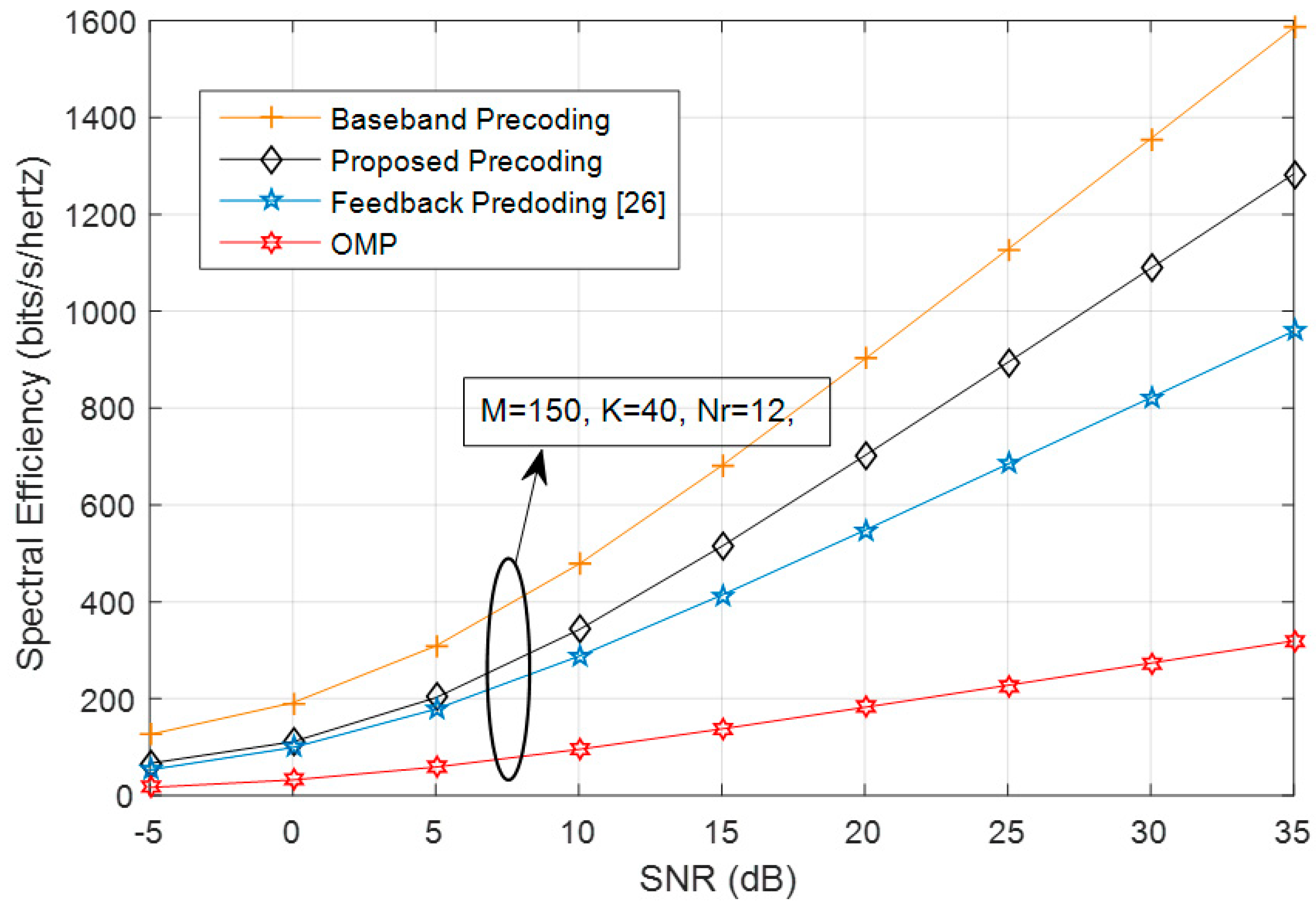
In this section, we have performed the simulation and discussed the simulation results. We used the realistic simulation parameters for the simulations, and the number of transmitter and receiver chains were set to be same for all the figures. Table 1 shows the simulation parameters used for the simulations, and the perfect CSI was assumed at the BS for simulations. Figure 3 compares the performance of the proposed and reference algorithms with respect to different signal-to-noise ratios. The number of transmitting antennae, users, and the transceiver chains were set to 150, 40, and 12, respectively. The proposed algorithm performed better than the reference feedback precoding and the orthogonal multiplexing pursuit (OMP) by converging near to the fully baseband precoder (Figure 3). The computational complexity of the proposed algorithm at the 5th step comes out to be O ( M × V A R F ) , and the overall computation complexity in terms of lambda big O notation can be written as O ( 2 W ( M × V A R F ) ) .
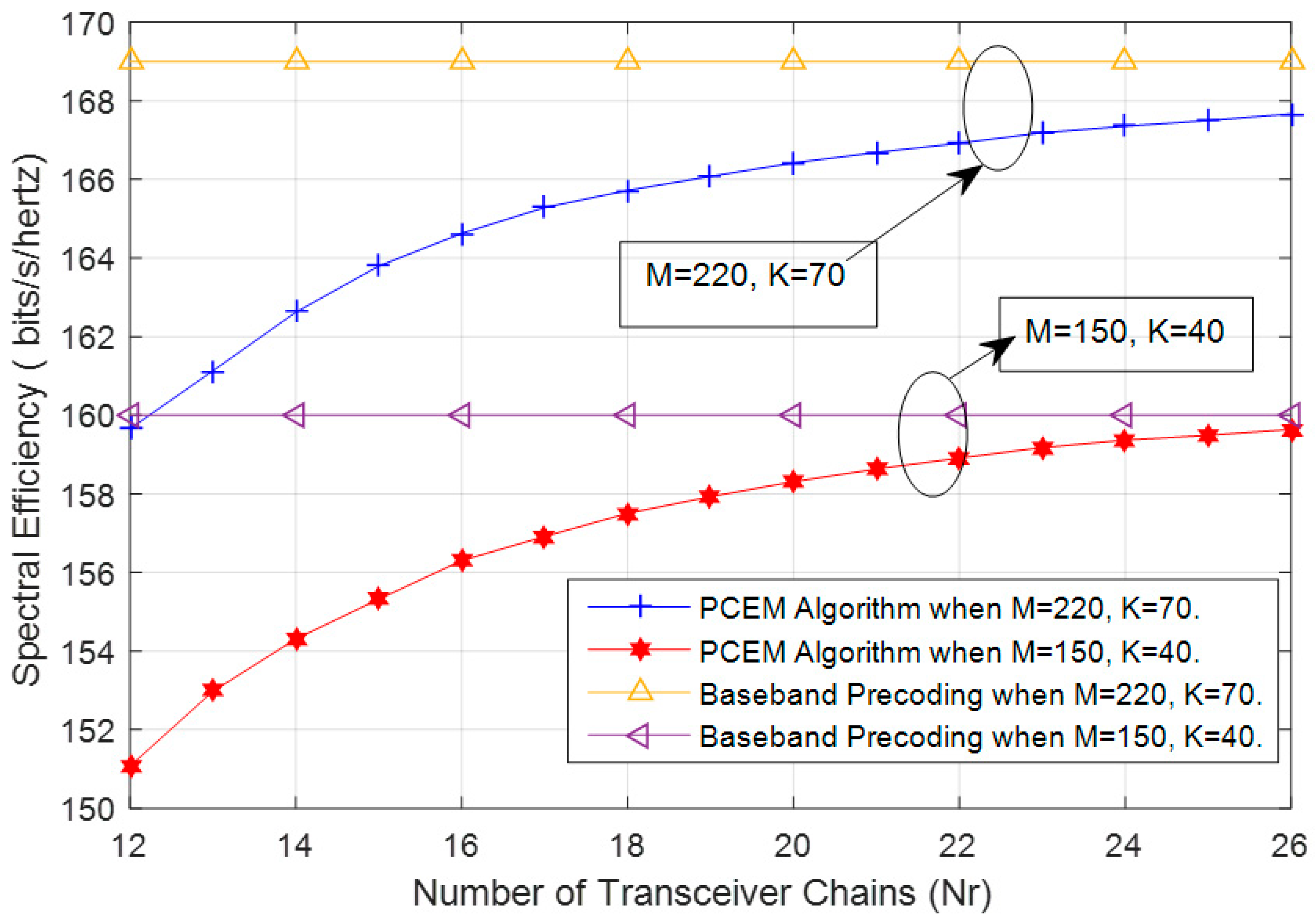
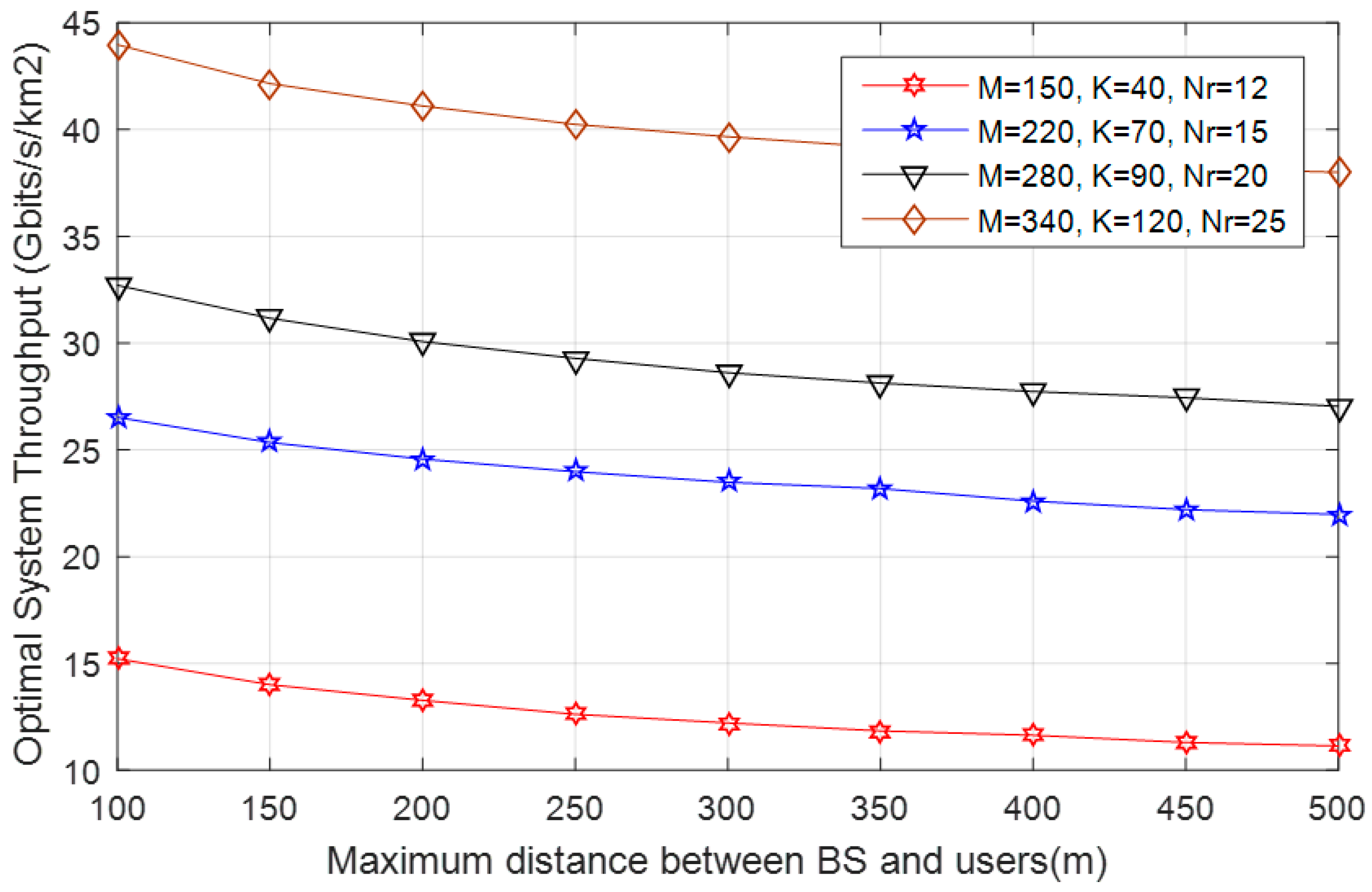
Figure 4 unveils the effects of the number of transceiver chains on the spectral efficiency of the system. Figure 4 shows that the spectral efficiency of the PCEM algorithm start approaches to the spectral efficiency achieved by adopting the baseband precoding when the number of transceiver chain increased, and the SNR was set to 0 dB in Figure 4. Figure 5 shows the optimal system throughput with respect to different distances. The maximum distance between the user terminals and base station varied from 100 m to 500 m, and the optimal system’s throughput was computed by varying the number of transmitting antennae, end users, and the transceiver chains.
The system provides the maximum throughput when the user terminals are closer to the base station, and the optimal throughput gets reduced when the user terminals are widely apart from the base station. Furthermore, the optimal throughput of the system comes out to be maximized when the base station is equipped with large number of transmitting antennas and the transceiver chains as can be seen in Figure 5.
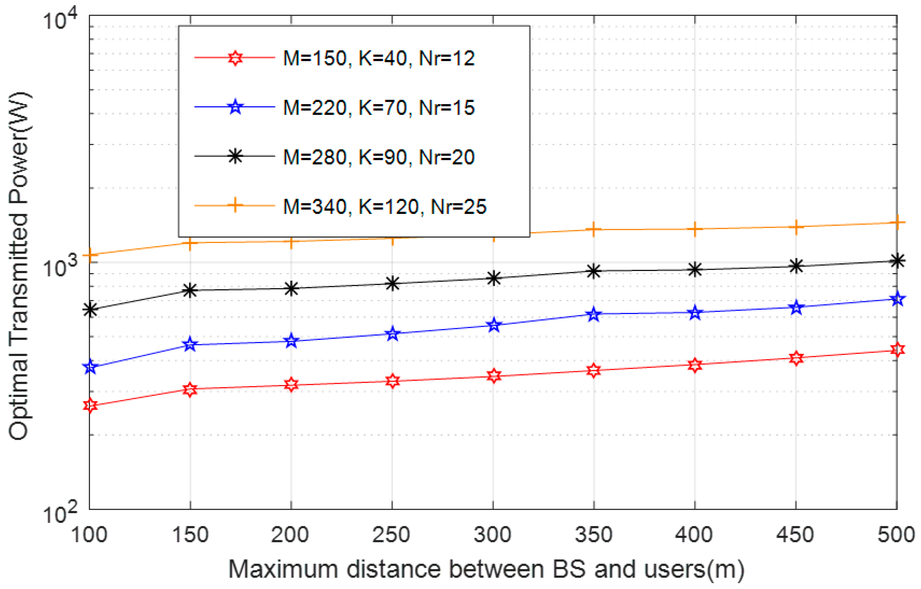
The optimal transmitted power, which results in the maximization of energy efficiency, can be seen in Figure 6. The optimal transmitted power was computed with respect to different distances, and when the user terminals and base station are widely apart, then the system needs to transmit more power in order to transmit the signal to the intended user terminals. Moreover, when the base station is equipped with a large number of antennae and transceiver chains, then the required optimal transmitted power is maximized as can be seen in Figure 6.
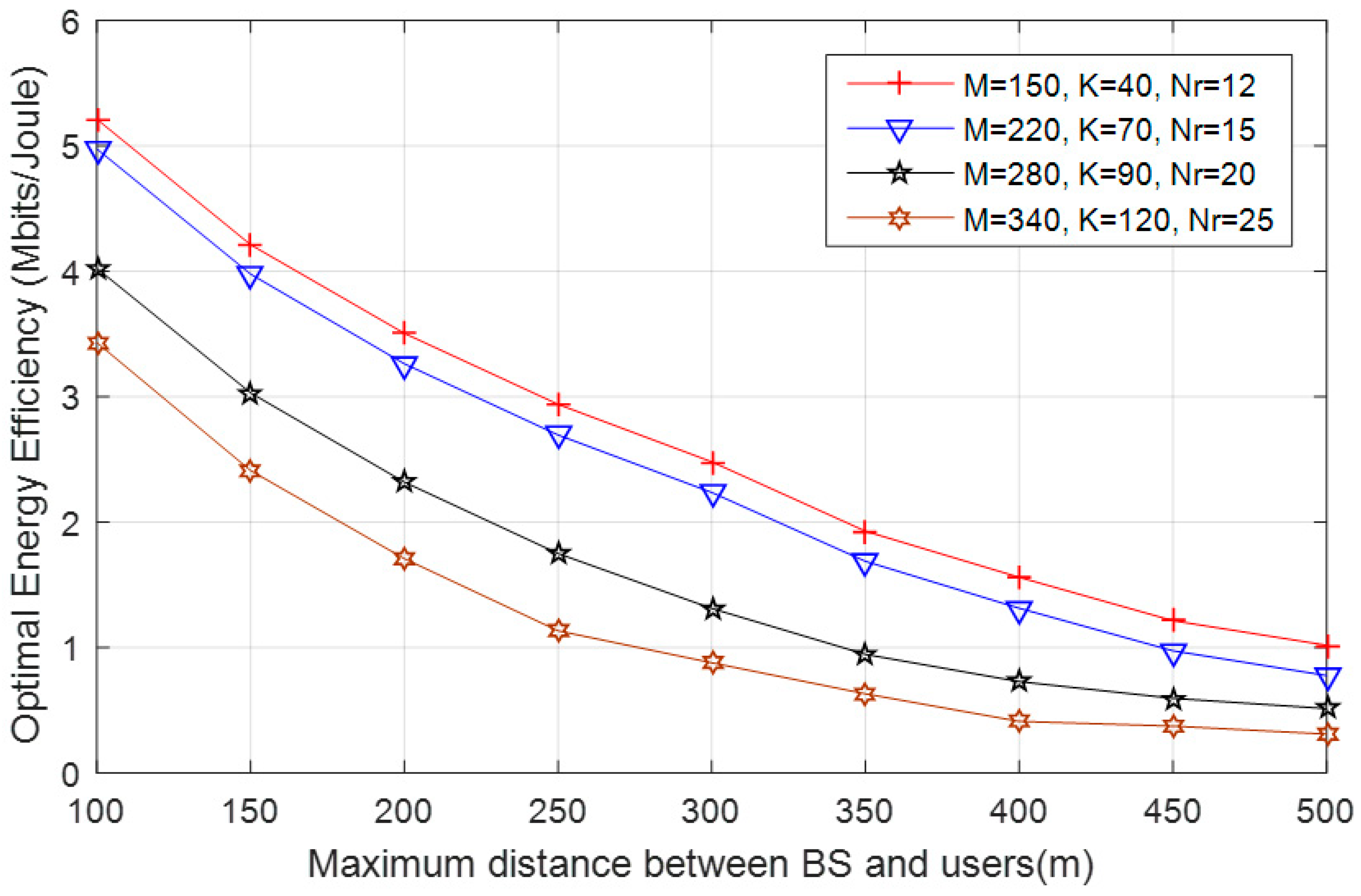
Figure 7 shows the optimal energy efficiency of the system with respect to different distances. The energy efficiency is computed at the different number of transmitting antennae, user terminals, and the transceiver chains. When the distance between the base station and user terminal increases, then the system needs to transmit more power and the optimal throughput of the system is reduced. This reduction in the system throughput and the increment in transmitting power results in the overall reduction of energy efficiency as can be seen in Figure 7.
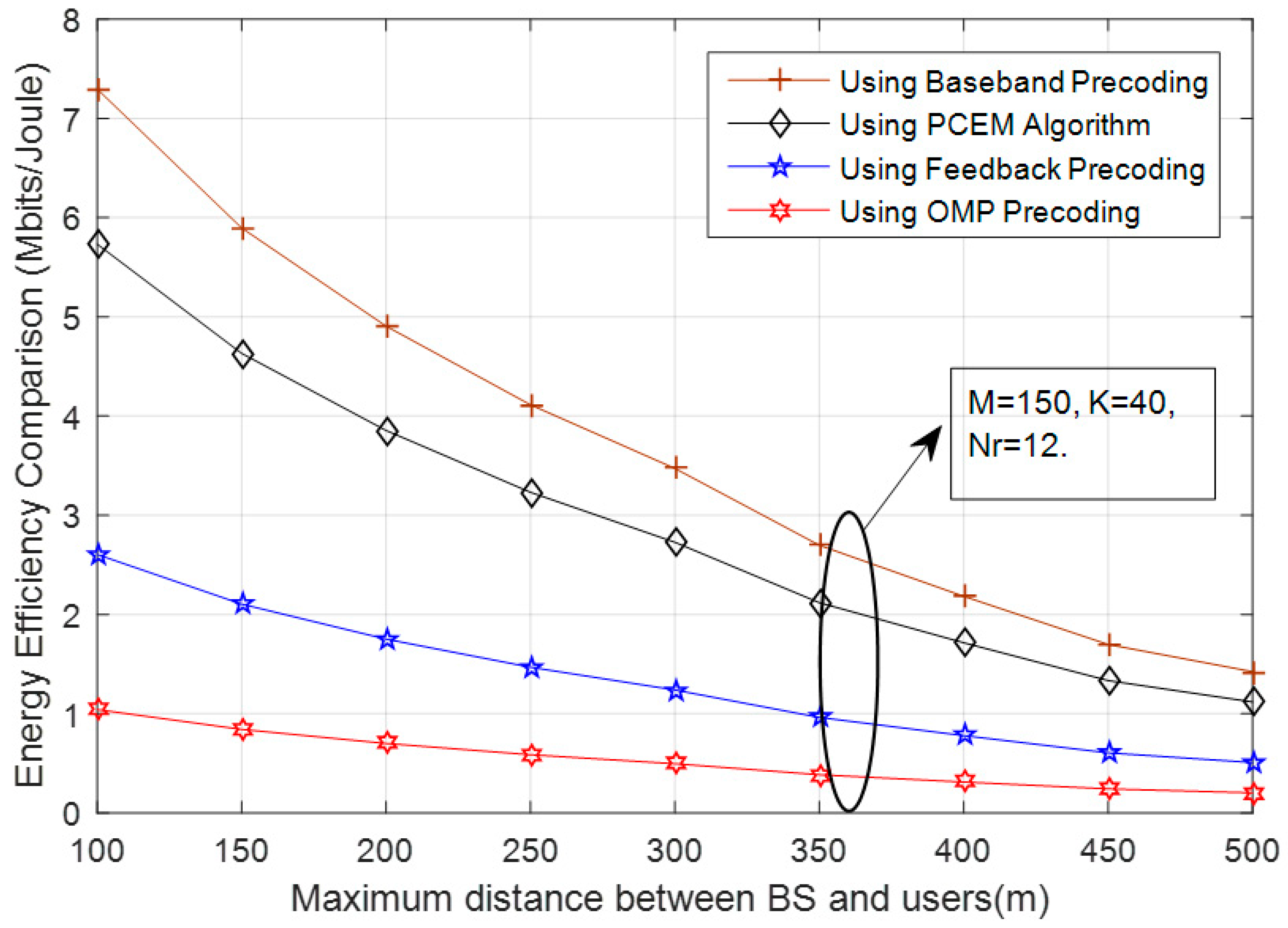
Figure 8 unveils the comparison between the proposed and reference algorithms in terms of the system’s overall energy efficiency. Reference algorithms work by optimizing the spectral efficiency of the system, whereas the proposed PCEM algorithm not only maximizes the spectral efficiency, but also provides the substantial increment in the overall energy efficiency of the system as can be seen in Figure 3 and Figure 8, respectively.

8. Conclusions

In this paper, we concentrated on energy efficiency when designing the mmWave Massive MIMO based on the hybrid precoders and decoders. We computed and modulated the spectral efficiency of mmWave Massive MIMO by using the combination of high dimension analogue precoder and low dimension digital percoder. The total power consumptions of mmWave Massive MIMO were accurately modeled by taking all the transmitted and consumed power from the transmitting side to the receiving end into account. We further proposed the Power Controlled Energy Maximization (PCEM) algorithm to maximize the overall energy efficiency of mmWave Massive MIMO, and the proposed algorithm worked by controlling the transmission power to balance the improved radiated energy efficiency and the increased power consumption for a given number of transceiver chains. The optimal spectral efficiency and the corresponding energy efficiency were computed with the help of the proposed algorithm at different distances. Furthermore, we noticed that the base station needs to have more transmitted power in order to cover a large distance, and the corresponding power consumption of the system also is increased. The simulation results compared the performance of the proposed algorithm with respect to reference algorithms, where it can be seen that the proposed algorithm works efficiently by converging near the fully digital precoder without much complexity.

Author Contributions

P.U., perceived the idea and worked on the mathematical modeling; A.A.K., worked on the optimization and simulations under the guidance of P.U. The most useful and significant contribution goes to P.U.

Acknowledgments

This work was supported by Suranaree University of Technology.

Conflicts of Interest

The authors declare no conflict of interest.

Appendix A

Proof of Theorem 1. 
The mmWave channel when the Uniform Linear Array (ULA) is implemented at the base station can be written as:
G = M × K N p l = 1 N p a l a K ( ϕ l K ) a M ( ϕ l M ) H
for the i th user and the mmWave channel can be written as:
G i = M × K N p l = 1 N p a l a K ( ϕ l i ) a M ( ϕ l i ) H
the path loss coefficient is assumed to be the same for all the rays and then the above equation can be rewritten as:
G i = a l M × K N p × [ a K ( ϕ 1 i ) a K ( ϕ N p i ) ] × [ a M ( ϕ 1 i ) a M ( ϕ N p i ) ]
where [ a K ( ϕ 1 i ) a K ( ϕ N p i ) ] has a dimension of K × N p , and [ a M ( ϕ 1 i ) a M ( ϕ N p i ) ] has a dimension of M × N p .
Similarly, the mmWave channel for the j th user can be written as:
G j = a l M × K N p × [ a K ( ϕ 1 j ) a K ( ϕ N p j ) ] × [ a M ( ϕ 1 j ) a M ( ϕ N p j ) ]
the product of the mmWave channel for the i th and j th user can be written as:
G i G j H = a l 2 ( M × K N p ) × a K ( ϕ l i ) × a M ( ϕ l i ) H × a M ( ϕ l i ) × a K ( ϕ l i ) H
as the azimuthal angles of departures and arrivals are distributed continuously, so we can write:
P [ lim M a M ( ϕ l i ) × a M ( ϕ l j ) H M ] = 0
by using the result of Equation (A1), we can write:
P [ lim M G i × G j H M ] = 0

Appendix B

Proof of Theorem 2. 
The Probability Distribution Function P D F , when the users are uniformly distributed, can be written as:
P D F = 2 x d max i 2 d min i 2
and, the expected value when the users are uniformly distributed can be written as:
E { γ ( x ) 1 } = x = d min i d max i x α 2 x d max i 2 d min i 2 d x
= 2 [ x α x 2 2 ( d max i 2 d min i 2 ) ( α x α 1 ) x 2 2 ( d max i 2 d min i 2 ) d x ] d min i d max i
= 1 d max i 2 d min i 2 [ x α + 2 α x α + 2 α + 2 ] d min i d max i
= 1 d max i 2 d min i 2 [ d max i α + 2 α d max i α + 2 α + 2 d min i α + 2 + α d min i α + 2 α + 2 ]
= 1 d max i 2 d min i 2 [ d max i α + 2 ( 1 α α + 2 ) d min i α + 2 ( 1 α α + 2 ) ]
E { γ ( x ) 1 } = 2 ( d max i 2 d min i 2 ) ( α + 2 ) [ d max i α + 2 d min i α + 2 ]

Appendix C

Energy efficiency can be written as:
E E ( p ) = a 1 × l o g 2 ( 1 + p a 2 ) a 3 p + a 4 + a 5 × l o g 2 ( 1 + p a 2 )
the E E ( p ) comes out to be quasi-concave if the level of the following set L k = { p : E E ( p ) k } is convex where k ε R [39]. The level of L k comes out to be less than zero for E E ( p ) < a 1 a 5 , so the L k is convex for k > a 1 a 5 . Furthermore, the level of L k is greater than zero for k < a 1 a 5 when p > 1 a 2 , so the second order derivate of E E ( p ) with respect to p should be less than zero. Hence, the E E ( p ) undergoes the quasi-concave response.

References

  1. Ramezani, P.; Jamalipour, A. Toward the evolution of wireless powered communication networks for the future Internet of Things. IEEE Netw. 2017, 31, 62–69. [Google Scholar] [CrossRef]
  2. Vu, T.X.; Chatzinotas, S.; Ottersten, B. Edge-caching wireless networks: Energy-efficient design and optimization. IEEE Trans. Wirel. Commun. 2018, 17, 2827–2839. [Google Scholar] [CrossRef]
  3. Cisco. Cisco Visual Networking Index: Global Mobile Data Traffic Forecast Update 2016–2021; White Paper; Cisco: San Jose, CA, USA, 2017. [Google Scholar]
  4. Liang, W.; Ng, S.X.; Hanzo, L. Cooperative overlay spectrum access in cognitive radio networks. IEEE Commun. Surv. Tutor. 2017, 19, 1924–1944. [Google Scholar] [CrossRef]
  5. Zorba, H.O. Spread spectrum versus non-spread spectrum techniques to combat mobile radio impairments. In Proceedings of the IEEE/AFCEA EUROCOMM 2000. Information Systems for Enhanced Public Safety and Security, Munich, Germany, 9–19 May 2000; pp. 228–232. [Google Scholar]
  6. Liang, Y.C.; Chen, K.C.; Li, G.Y.; Mahonen, P. Cognitive radio networking and communications: An overview. IEEE Trans. Veh. Technol. 2011, 60, 3386–3407. [Google Scholar] [CrossRef]
  7. Hidayah, N.; Adnan, M.; Rafiqul, I.M.; Zahirul Alam, A.H.M. Massive MIMO for Fifth Generation (5G): Opportunities and Challenges. In Proceedings of the 2016 International Conference on Computer and Communication Engineering (ICCCE), Kuala Lumpur, Malaysia, 26–27 July 2016; pp. 47–52. [Google Scholar]
  8. Han, S.; Chih-Lin, I.; Xu, Z.; Rowell, C. Large-scale antenna systems with hybrid analog and digital beamforming for millimeter wave 5G. IEEE Commun. Mag. 2015, 53, 186–194. [Google Scholar] [CrossRef]
  9. Wong, V.W.S.; Schober, R.; Ng, D.W.K.; Wang, L. Key Technologies for 5G Wireless Systems, 1st ed.; Cambridge University Press: Cambridge, MA, USA, 2017. [Google Scholar]
  10. Wu, Q.; Li, G.Y.; Chen, W.; Ng, D.W.K.; Schober, R. An Overview of Sustainable Green 5G Networks. IEEE Wirel. Commun. 2017, 24, 72–80. [Google Scholar] [CrossRef] [Green Version]
  11. Guariglia, E. Entropy and fractal antennas. Entropy 2016, 18, 84. [Google Scholar] [CrossRef]
  12. Ahmad Khan, A.; Uthansakul, P.; Duangmanee, P.; Uthansakul, M. Energy Efficient Design of Massive MIMO by Considering the Effects of Nonlinear Amplifiers. Energies 2018, 11, 1045. [Google Scholar] [CrossRef]
  13. Uthansakul, P.; Ahmad Khan, A.; Uthansakul, M.; Duangmanee, P. Energy Efficient Design of Massive MIMO Based on Closely Spaced Antennas: Mutual Coupling Effect. Energies 2018, 11, 2029. [Google Scholar] [CrossRef]
  14. El Ayach, O.; Rajagopal, S.; Abu-Surra, S.; Pi, Z.; Heath, R.W. Spatially sparse precoding in millimeter wave MIMO systems. IEEE Trans. Wirel. Commun. 2014, 13, 1499–1513. [Google Scholar] [CrossRef]
  15. Payami, S.; Ghoraishi, M.; Dianati, M. Hybrid beamforming for large antenna arrays with phase shifter selection. IEEE Trans. Wireless Commun. 2016, 15, 7258–7271. [Google Scholar] [CrossRef]
  16. Ni, W.; Dong, X.; Lu, W.S. Near-optimal hybrid processing for massive MIMO systems via matrix decomposition. IEEE Trans. Signal Process. 2015, 65, 3922–3933. [Google Scholar] [CrossRef]
  17. Alkhateeb, A.; El Ayach, O.; Leus, G.; Heath, R.W. Channel estimation and hybrid precoding for millimeter wave cellular systems. IEEE J. Sel. Topics Signal Process. 2014, 8, 831–846. [Google Scholar] [CrossRef]
  18. Rappaport, T.S.; Maccartney, G.R.; Samimi, M.K.; Sun, S. Wideband millimeter-wave propagation measurements and channel models for future wireless communication system design. IEEE Trans. Commun. 2015, 63, 3029–3056. [Google Scholar] [CrossRef]
  19. Heath, R.W.; Gonzalez-Prelcic, N.; Rangan, S.; Roh, W.; Sayeed, A. An overview of signal processing techniques for millimeter wave MIMO Systems. IEEE J. Spec. Top. Signal Process. 2016, 10, 436–453. [Google Scholar] [CrossRef]
  20. Singh, J.; Ponnuru, S.; Madhow, U. Multi-Gigabit communication: The ADC bottleneck. In Proceedings of the IEEE International Conference on Ultra-Wideband, Vancouver, BC, Canada, 9–11 September 2009; pp. 47–52. [Google Scholar]
  21. Love, D.J.; Heath, R.W. Equal gain transmission in multiple-input multiple-output wireless systems. IEEE Trans. Commun. 2003, 51, 1102–1110. [Google Scholar] [CrossRef] [Green Version]
  22. Baykas, T.; Sum, C.S.; Lan, Z.; Wang, J.; Rahman, M.A.; Harada, H.; Kato, S. IEEE 802.15.3c: The first ieee wireless standard for data rates over 1 Gb/s. IEEE Commun. Mag. 2011, 49, 114–121. [Google Scholar] [CrossRef]
  23. Hur, S.; Kim, T.; Love, D.J.; Krogmeier, J.V.; Thomas, T.A.; Ghosh, A. Millimeter wave beamforming for wireless backhaul and access in small cell networks. IEEE Trans. Commun. 2013, 61, 4391–4403. [Google Scholar] [CrossRef]
  24. Hajimiri, A.; Hashemi, H.; Natarajan, A.; Guan, X.; Komijani, A. Integrated phased array systems in silicon. Proc. IEEE 2005, 93, 1637–1655. [Google Scholar] [CrossRef]
  25. Doan, C.H.; Emami, S.; Sobel, D.A.; Niknejad, A.M.; Brodersen, R.W. Design considerations for 60 GHz CMOS radios. IEEE Commun. Mag. 2004, 42, 132–140. [Google Scholar] [CrossRef]
  26. Alkhateeb, A.; Leus, G.; Heath, R.W. Limited Feedback Hybrid Precoding for Multi-User Millimeter Wave Systems. IEEE Trans. Wirel. Commun. 2015, 14, 6481–6494. [Google Scholar] [CrossRef] [Green Version]
  27. Alkhateeb, A.; El Ayach, O.; Leus, G.; Heath, R. Hybrid precoding for millimeter wave cellular systems with partial channel knowledge. In Proceedings of the Information Theory and Applications Workshop (ITA), San Diego, CA, USA, 10−15 February 2013; pp. 1–5. [Google Scholar]
  28. Kim, C.; Kim, T.; Seol, J. Multi-beam transmission diversity with hybrid beamforming for MIMO-OFDM systems. In Proceedings of the IEEE Globecom Workshops (GC Wkshps), Atlanta, GA, USA, 9–13 December 2013; pp. 61–65. [Google Scholar]
  29. Drineas, P.; Mahoney, M.W. On the Nyström method for approximating a gram matrix for improved Kernel-based learning. J. Mach. Learn. Res. 2005, 6, 2153–2475. [Google Scholar]
  30. Jain, P.; Netrapalli, P.; Sanghavi, S. Low-rank matrix completion using alternating minimization. In Proceedings of the 45th ACM Symp. Theory Comput. (STOC), Palo Alto, CA, USA, 1–4 June 2013; pp. 665–674. [Google Scholar]
  31. Yu, X.; Juei-Chin, S.; Zhang, J.; Letaief, K. Alternating Minimization Algorithms for Hybrid Precoding in Millimeter Wave MIMO Systems. IEEE J. Sel. Top. Signal Process. 2016, 10, 485–500. [Google Scholar] [CrossRef] [Green Version]
  32. Venkateswaran, V.; Pivit, F.; Guan, L. Hybrid RF and digital beamformer for cellular networks: Algorithms, microwave architectures, and measurements. IEEE Trans. Microw. Theory Tech. 2016, 64, 2226–2243. [Google Scholar] [CrossRef]
  33. Sudarshan, P.; Mehta, N.B.; Molisch, A.F.; Zhang, J. Antenna selection with RF pre-processing: Robustness to RF and selection nonidealities. In Proceedings of the IEEE Radio Wireless Conference, Atlanta, GA, USA, 22 September 2004; pp. 665–674. [Google Scholar]
  34. Garcia-Rodriguez, A.; Venkateswaran, V.; Rulikowski, P.; Masouros, C. Hybrid analog–digital precoding revisited under realistic RF modeling. IEEE Wireless Commun. Lett. 2016, 5, 528–531. [Google Scholar] [CrossRef]
  35. Méndez-Rial, R.; Rusu, C.; González-Prelcic, N.; Alkhateeb, A.; Heath, R.W. Hybrid MIMO architectures for millimeter wave communications: Phase shifters or switches? IEEE Access 2016, 4, 247–267. [Google Scholar] [CrossRef]
  36. Tsinos, C.G.; Maleki, S.; Chatzinotas, S.; Ottersten, B. On the energy-efficiency of hybrid analog-digital transceivers for large antenna array systems. IEEE J. Sel. Areas Commun. 2017, 35, 1980–1995. [Google Scholar] [CrossRef]
  37. Wei, Z.; Ng, D.W.K.; Yuan, J. NOMA for Hybrid MmWave Communication Systems with Beamwidth Control. IEEE J. Sel. Top. Signal Process. 2019, in press. [Google Scholar] [CrossRef]
  38. Wu, X.; Liu, D.; Yin, F. Hybrid Beamforming for Multi-User Massive MIMO Systems. IEEE Trans. Commun. 2018, 66, 3879–3891. [Google Scholar] [CrossRef]
  39. Khan, A.A.; Uthansakul, P.; Uthansakul, M. Energy Efficient Design of Massive MIMO by Incorporating with Mutual Coupling. Int. J. Commun. Antenna Prop. 2017, 7, 198–207. [Google Scholar] [CrossRef]
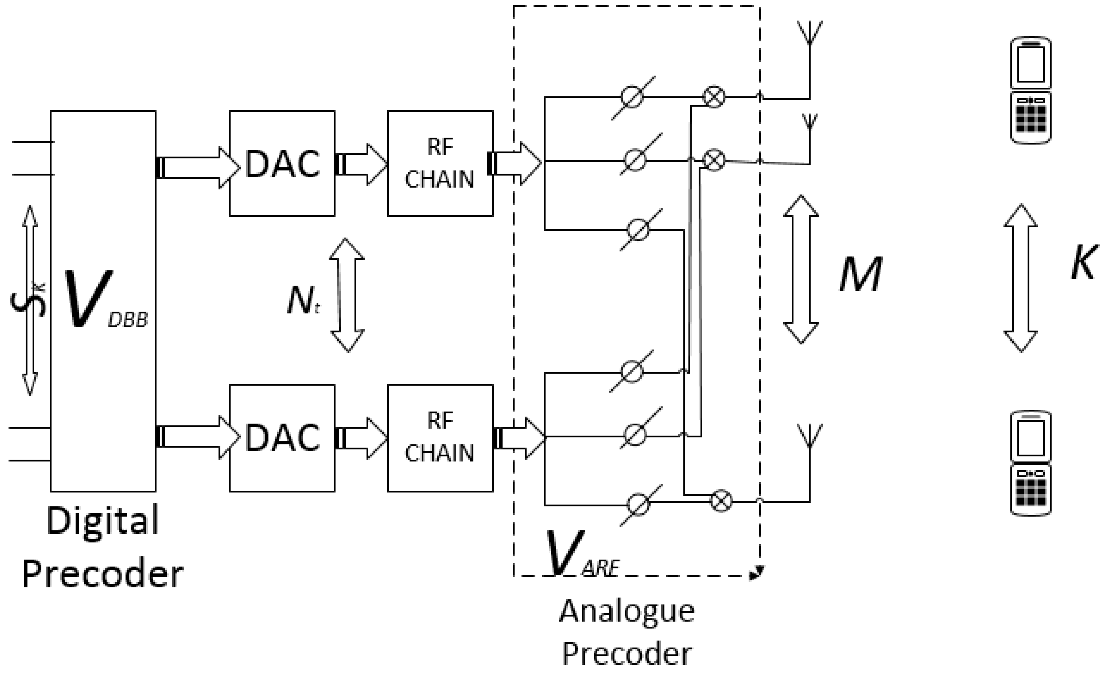
Figure 1. Millimeter wave massive MIMO.
Energies 12 02227 g001
Figure 2. Euclidean projection.
Energies 12 02227 g002
Figure 3. Spectral efficiency and the comparison between the proposed and reference algorithms.
Energies 12 02227 g003
Figure 4. Effects of the number of transceiver chains on the spectral efficiency.
Energies 12 02227 g004
Figure 5. Optimal system throughput.
Energies 12 02227 g005
Figure 6. Optimal transmitted power.
Energies 12 02227 g006
Figure 7. Optimal energy efficiency.
Energies 12 02227 g007
Figure 8. Comparison of the energy efficiency of proposed and the reference algorithms.
Energies 12 02227 g008
Table 1. Simulation parameters.
ParameterValue
Transmission Bandwidth ( B )20 MHz
Coherence Block ( U )1800
Fixed power ( P F x )18 W
Mixer power ( P m i x )19 mW
LNA power ( P L N A )14 mW
Path loss exponent ( α )3.8
Shifters power ( P p s )30 mW
Total Noise Power ( B α 2 )‒96 dBm
Total Pilot Length ( T t o t )2 m
Oscillator power ( P o c )5 mW
Phase shifters power ( P s )0.5 dB
Combiners power ( P c )0.6 dB
Number of Transceiver chains when fixed ( N t , N r )8
Coding power ( P c )0.7 W
Decoding power ( P d )0.2 W
Minimum distance between the BS and users ( d min i )32 m