1. Introduction
With the development of human society, the problem of global warming caused by greenhouse gas emission has intensified accordingly, and the importance of energy conservation and emission reduction becomes more and more prominent [
1,
2]. As one of the most serious industries resulting in greenhouse gas emissions, the transportation industry has attracted the attention of countries all around the world [
3]. Starting with the transportation industry for clean energy replacement is undoubtedly an effective way to alleviate environmental problems.
As a well-known clean energy source, electrical energy can be converted from a variety of renewable energy sources. Compared with traditional vehicles powered by fossil fuels, electric vehicles (EVs), which are driven by electric energy, have a unique zero-emission advantage that fuel vehicles cannot match. That is why EVs are undoubtedly the best choice for the transportation industry in order to promote energy structure optimization. However, the high cost, limited capacity, and cruising range of electric vehicle battery packs limit the further promotion of EVs.
Compared with the traditional plug-in charging method, there is no physical connection between the source and the load during the wireless power transmission (WPT) charging process, therefore the charging process is safer and more convenient, which makes WPT a promising energy supplement method [
4,
5,
6]. The WPT technology applied to EVs is divided into static wireless power transmission (SWPT) and dynamic wireless power transmission (DWPT). DWPT charging is developed on the basis of SWPT charging, which can effectively reduce the volume of the vehicle battery pack, increase the cruising range, and further improve the flexibility of the charging process [
7,
8,
9].
At present, the optimization of the DWPT system mainly focuses on the optimization of the charging power and coil segment allocation. The authors of [
10] proposed an optimal power distribution scheme for multi-objective WPT systems, without communication networks. In the literature [
11], a charging area determination method for the double excitation unit wireless power transmission (DEU-WPT) system for EV dynamical charging is proposed. On this basis, a switching control method was proposed to switch the work mode of the system when the EV enters the charging area, which is beneficial for improving the system power capacity, without increasing the voltage and current stress. In the literature [
12], Jiang et al. proposed a control strategy with a zero voltage switching angle (ZVSA) loop to realize the constant current (CC) charging for the battery, and to achieve the zero voltage switching (ZVS) operation of the primary inverter. In the literature [
13], a highly efficient nonlinear parity-time (PT)-symmetric model for wireless power transfer (WPT) was proposed. The theoretical analysis shows that the proposed system automatically achieves a constant output power with a constant transfer efficiency against the variation of the coupling coefficient. In the literature [
14], Liu et al. observed that the transfer power can be controlled by regulating either the phase-shift angle or the direct current (DC)-link voltage. Therefore, a phase-shift angle and DC-link voltage combined control method is proposed in order to improve the system efficiency, dynamic response, and widened the adjustable power range.
On the other hand, some researchers have studied the length optimization of the segmented power transmitting coil of the DWPT system. The authors of [
15] proposed a methodology based on mathematical optimization for the simultaneous design of an EV speed profile and for the allocation of WPT system in a lane segment. The authors of [
16] analyzed the driving characteristics of the EVs and features of the super-capacitor, aiming at achieving the minimum investment cost of the EV’s dynamic wireless charging system by taking the energy storage devices and length of the power supply rail as the constraints, based on the particle swarm genetic algorithm.
However, the inconsistent lengths of each segment rail will cause differences in the rail standards and increase the difficulty of the system management. Considering that the travelling EVs will not always be driving at a constant speed, the driving speed of the EVs will strongly affect the charging time, which further affects the total amount of charging power during a fixed length. This paper focuses on a charging power control method adapting to speed change. The DWPT system considered in this paper is proposed in order to combine the driving speed of EVs with the relevant energy consumption standard, and to adjust the self-charging power in a targeted manner by adjusting the EV’s own parameters, making the energy properly distributed among the EVs. The purpose of the DWPT system is to make full use of the EVs’ travelling time in the wireless charging section. Therefore, the above is an accurate realization of this goal.
In
Section 2, a long-track DWPT charging system is outlined. A circuit model with a long primary-side transmitting coil and multi secondary coils is built. The equations of the receiving power of each EV are derived. In
Section 3, the range of the transmitting-side voltage and the vehicle-side equivalent load resistance value are discussed, respectively, and then the method for determining the load resistance value under multi-EV charging conditions is further discussed. In
Section 4, EV dynamic wireless charging process control method adapting to speed variation is proposed. The experimental prototype with the application of the above-mentioned control method is built, and the theoretical analysis is verified by the experimental results.
2. System Introduction
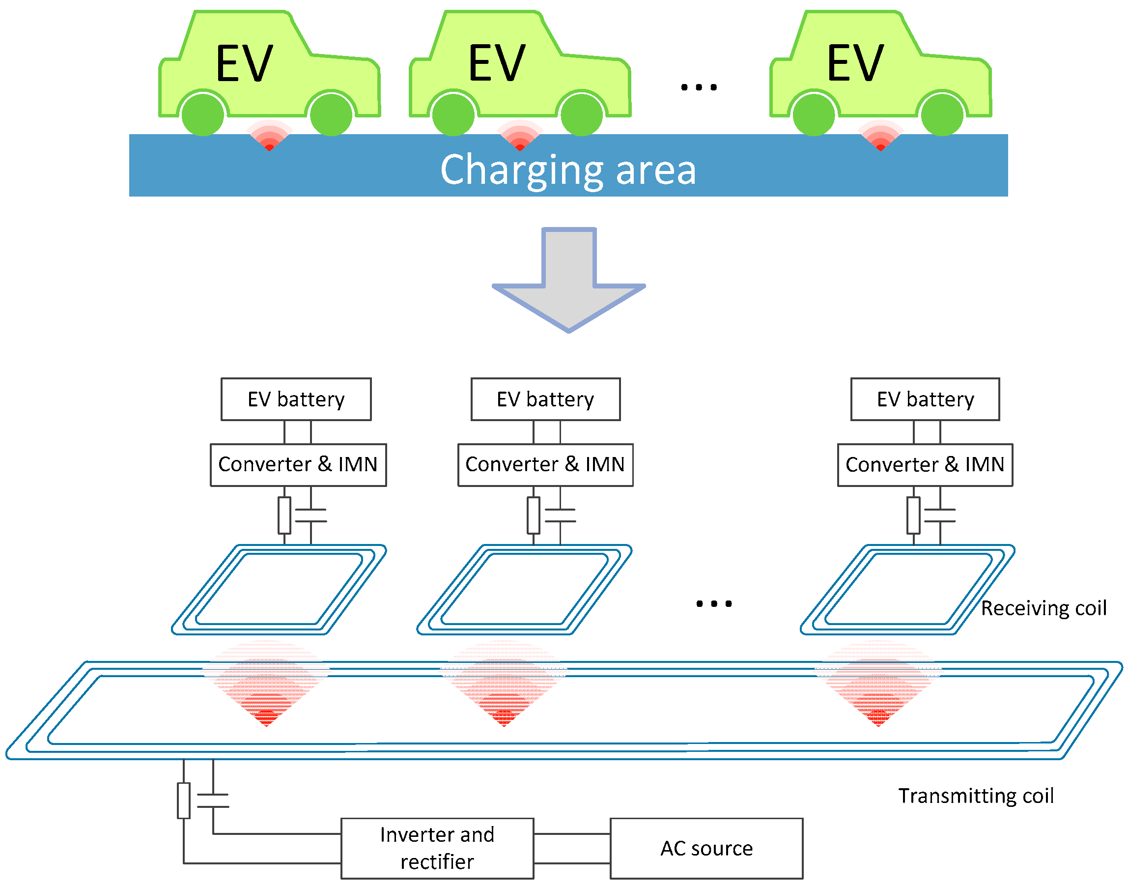
To realize the DWPT for EVs, a dynamic wireless charging area can be formed by laying a long wireless power transmitting coil beneath the road surface; a power receiving coil is mounted on the vehicle chassis, therefore the electric power can be rectified and supplied to EVs’ battery by means of magnetic coupling resonance while the EVs are traveling in the charging area.
Figure 1 is a schematic diagram of the long-track DWPT system.
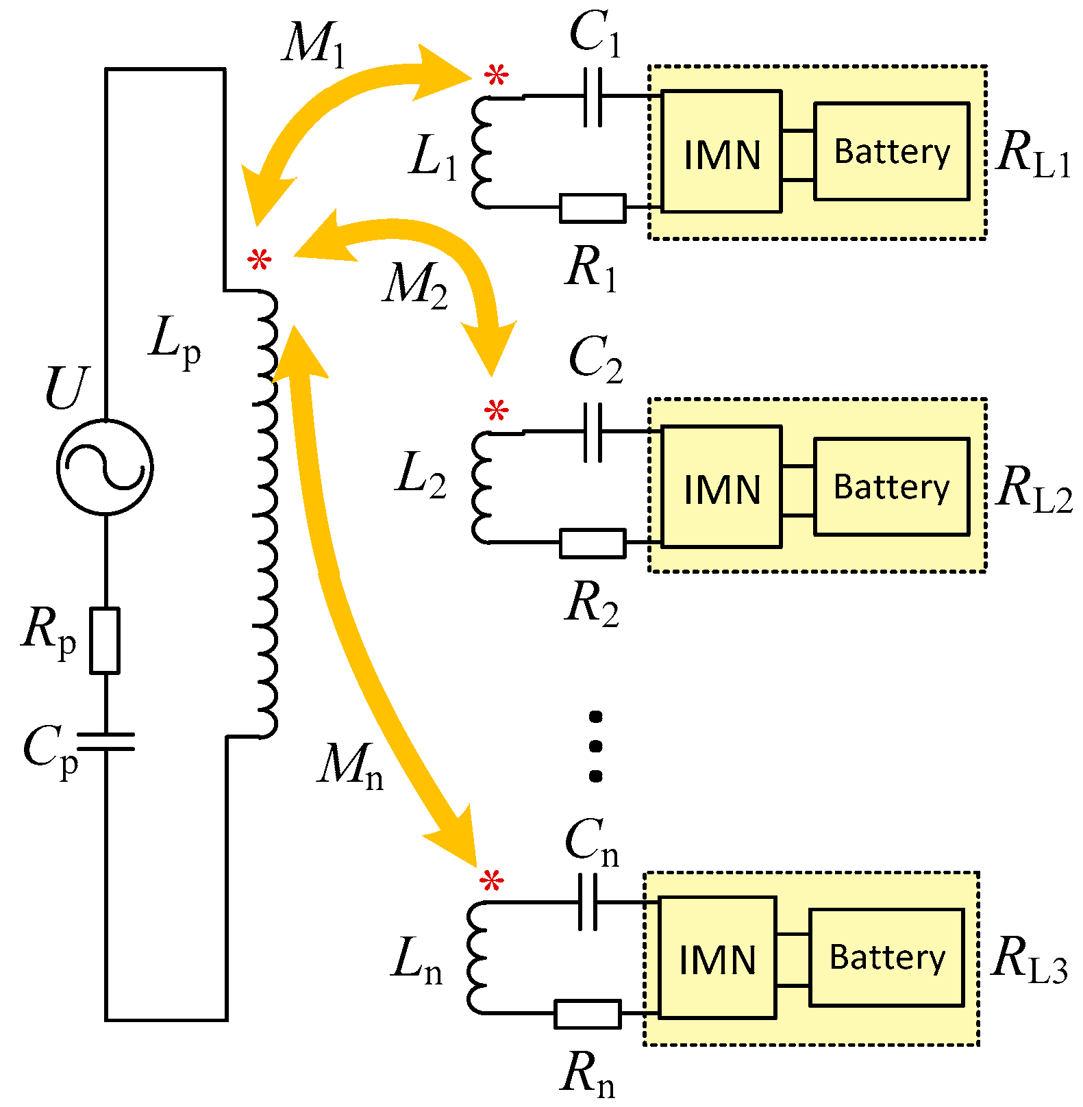
The equivalent circuit diagram of the above-mentioned long-track EV DWPT system is shown in
Figure 2, where
is the output voltage value after rectification and inversion;
is the transmitting-side equivalent resistance value;
are the equivalent internal resistance of the power receiving coils of the first, second, and nth vehicles, respectively;
is the transmitting coil inductance value;
are the inductance value of the first, second, and nth vehicles’ power receiving coils, respectively;
is the transmitting-side resonance compensation capacitor; and
are the receiving side resonant compensation capacitors of the first, second, and nth EVs. Considering that the horizontal distance between the vehicles is much larger than the geometry of the vehicle-side power receiving coil, when analyzing the circuit, we prefer to ignore the mutual inductance between the vehicle receiving coils. In other words, we only consider the mutual inductance between the vehicle-side power receiving coil and the power transmitting coil (
)
are the equivalent load impedance of the receiving side of the first, second, and nth EVs, which can be adjusted through an impedance matching network (IMN).
The equivalent KVL (Kirchhoff Voltage Law) equation of the system can be obtained from
Figure 2.
ω is the resonance angular frequency of the system. The equivalent impedance of the power transmitting-side is , and the equivalent impedance of each vehicle is . In order to make the system work in the resonance state, and need to satisfy , and each pair of and needs to satisfy .
From the above equation, the transmitting-side current
and the receiving-side current
of the system can be obtained as follows:
Therefore, the charging power of each electric vehicle under resonance is correspondingly obtained as follows:
Considering that in the long-track DWPT system studied in this paper, the geometry of the transmitting coil is much larger than that of the vehicle-side power receiving coil, and the geometrical dimensions of the power receiving coils are uniform, we let
. It can be considered that the mutual inductance between each power receiving coil and the transmitting coil is approximately equal, that is
. To further simplify the analysis, assuming that the EV models in the charging area are the same, and the vehicle-side equivalent load impedance value is
in the initial state, the charging power of a single EV can be expressed as the following:
3. Method of Determining the Vehicle-Side Equivalent Load Resistance Value
3.1. Determination of the Range of the Transmitting-Side Voltage and the Vehicle-Side Equivalent Load Resistance Value
Considering that the object of the DWPT service system is EV in the charging area, the ideal charging power control method should be that the system adjusts its own parameters according to the EV driving speed, so as to adapt to the driving state of the EV, thereby realizing a flexible energy supplement. Therefore, this paper considers adjusting the system parameters according to the lower limit of the charging power demand associated with different speeds in order to achieve the EV charging power control.
Before investigating the multi-vehicle charging situation in the charging area, it is necessary to determine the size of the transmitting coil by the “two-second principle”. According to the maximum speed limit of 60 km/h, the safety distance between the adjacent vehicles is about 33.33 m. In this paper, the EV parameters are set with reference to BYD e5. The length and width of the vehicle are 4.68 m and 1.765 m, respectively. Assuming that the charging area can accommodate up to three vehicles for simultaneous charging, the length of the transmitting coil is approximately equal to = (33.33 + 4.68) × 3 = 114.03 m, and we take an integer to make the length of the transmitting coil 120 m. In order to reduce the influence of the offset between the coupling device and to make full use of the effective area of the vehicle chassis at the same time, we set the transmitting coil width to 1.5 m, and the vehicle receiving coil size to 1 m × 1 m.
In this paper, for the vehicle to be charged in the charging area, the charging power that the long-track DWPT charging system needs to provide is determined according to the power consumption per unit kilometer of the vehicle, expressed by . Known by Joule’s law, , and , where is the length of the road section (1 km), is the driving speed, and is the time it takes for the vehicle to travel 1 km. Therefore, the relationship between the critical charging power of a single vehicle and the driving speed is , which means that if the charging power wants to offset the vehicle’s unit kilowatt-hour power consumption, , when the driving speed is , the charging power cannot be less than .
Taking BYD e5 as an example, the power consumption per unit kilometer of a single vehicle is 0.15 kWh. We set the speed interval of the vehicle during dynamic charging to 0~60 km/h—the lower limit of the charging power of a single vehicle corresponding to the vehicle speed of 60 km/h is 9 kW. Therefore, it is possible to determine the range of the transmitting-side voltage and load value at different driving speeds by
, in conjunction with Equation (4). The specific parameters of the DWPT system are shown in
Table 1.
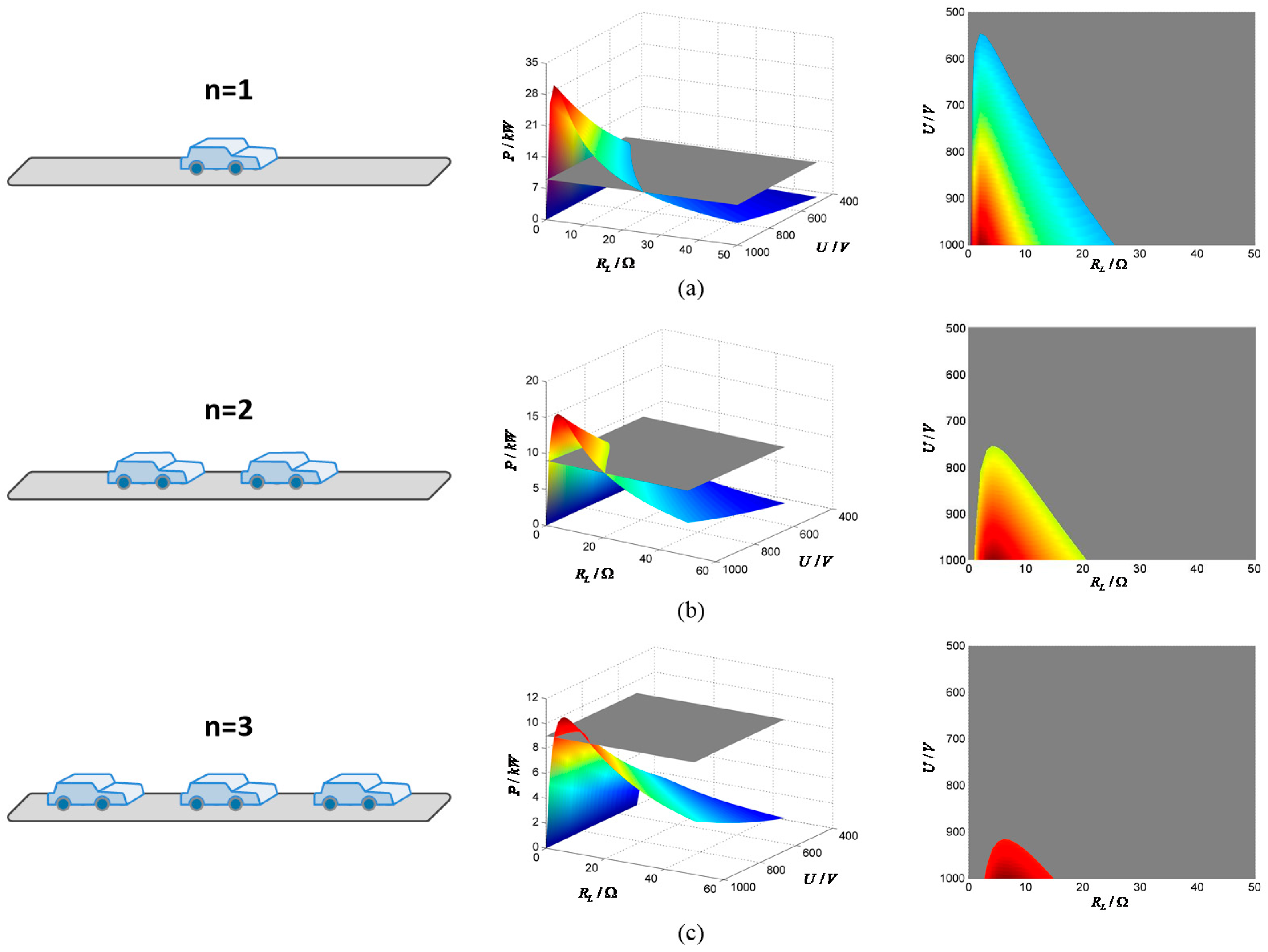
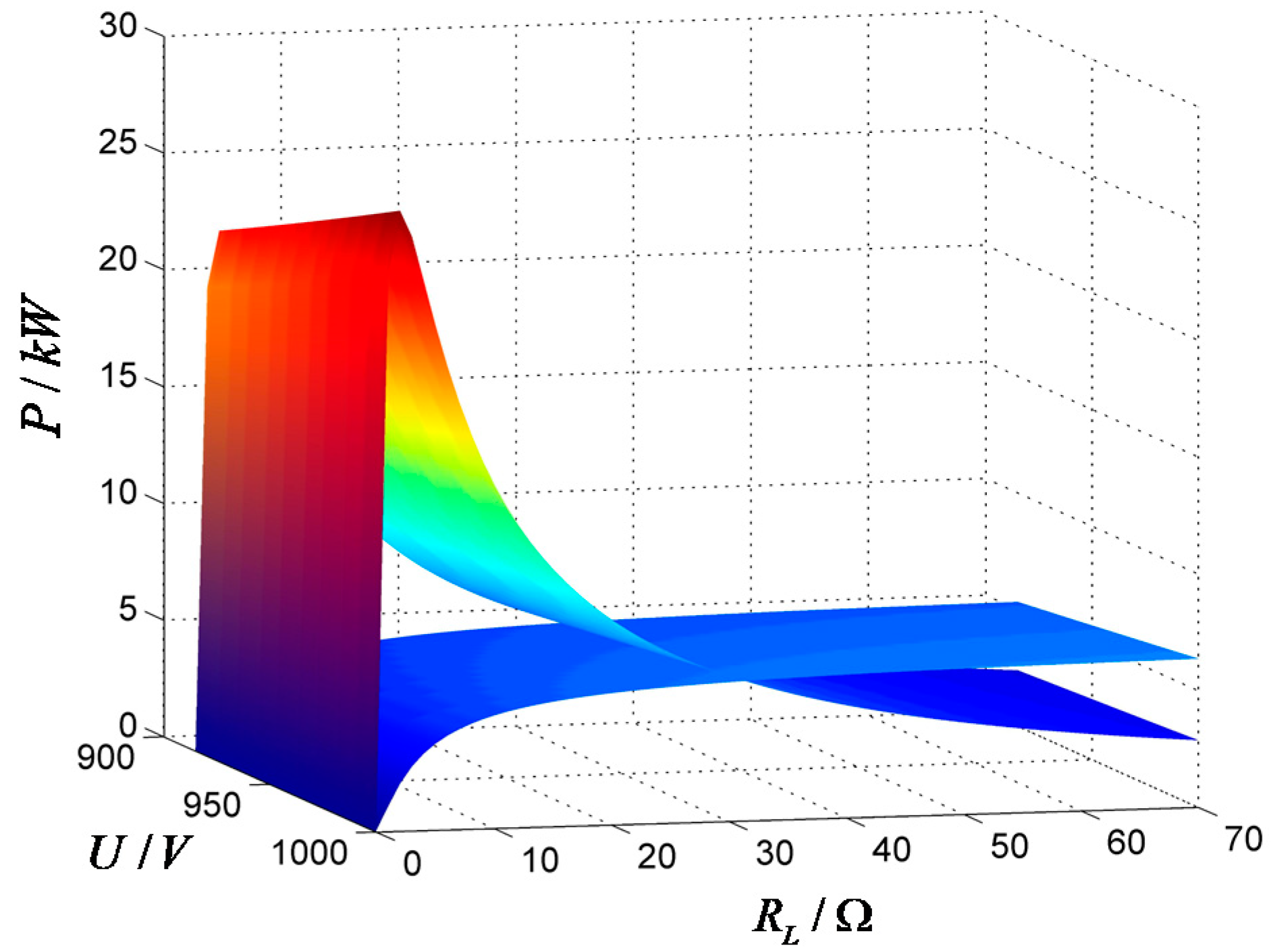
Bringing the parameters in
Table 1 into Equation (4), we can get the variation trend of the charging power of a single vehicle with a change of
and
when the number of vehicles n in the charging area is different, as shown in
Figure 3.
From
Figure 3, we can see that the charging power increases first and then decreases with the increase of
, and increases with the increase of
. The more charging vehicles in the charging area, the smaller the range of the transmitting-side voltage and the vehicle-side equivalent load value adjustment is. Therefore, considering the compatibility of the actual application, in order to charge a maximum of three EVs using by one transmitting coil, the voltage range of the transmitting-side power source takes the intersection of the above three cases, that is, 900 V~1000 V.
3.2. Determination of the Vehicle-Side Critical Load Resistance Value While Multiple Charging
It can be seen from
Figure 3, that because of for a given charging power lower limit (
), the same voltage value corresponds to a larger critical resistance (
) and a smaller critical resistance (
). Under the same change step, the charging power changes more sharply with
, while the change with
is more moderate. Considering the stability of the system operation, in order to avoid the excessive power fluctuation caused by the change of
, the larger load resistance value corresponding to the same voltage is selected for analysis.
and Equation (4) are linked together so as to obtain an equation about the charging power.
Assuming that all of the EVs within the same power transmitting coil drive at the same speed (
), the expression of the critical load resistance value of each vehicle (
RL0), which satisfies the above requirements, can be solved by Equation (5), as follows:
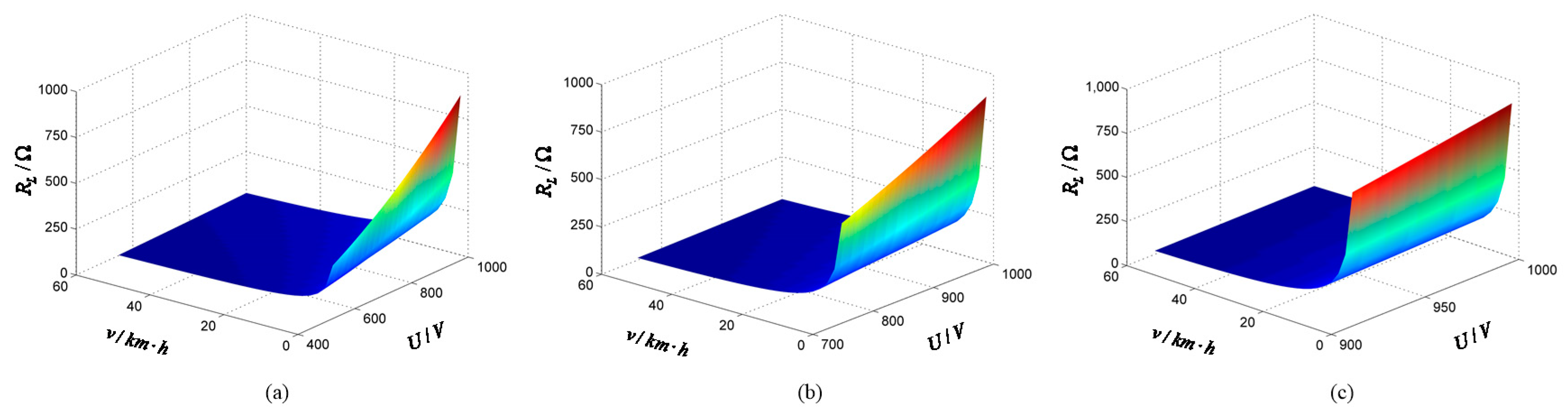
For the DWPT charging system analyzed in this paper, the system resonant frequency, the parameters of the coupling device, and the distance between the chassis and the road surface are fixed. Therefore, the driving speed (
) and the transmitting-side voltage (
) are the main parameters affecting the critical load value (
). According to the range of
under a different n in
Figure 3, the variation law of the critical load value of each vehicle under different charging vehicle numbers is obtained, as shown in
Figure 4.
By adjusting
to
according to the EV number (n) and driving speed (
), as shown in
Figure 4, the charging power of each EV can offset the vehicle’s unit kilowatt-hour power consumption (
) while driving at the speed of
.
4. EV Dynamic Wireless Charging Process Control Method Adapting to Speed Variation
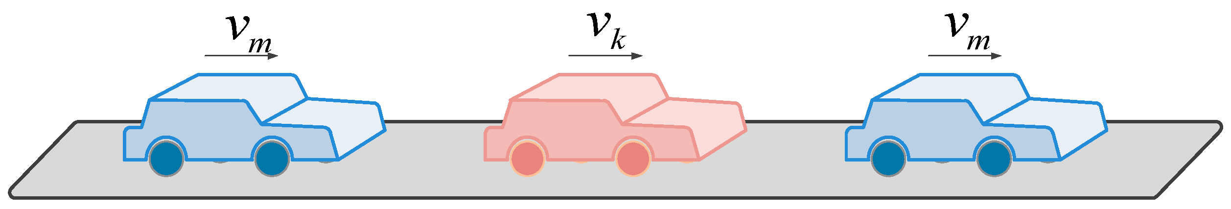
However, under actual conditions, the EVs in the charging area cannot always maintain the ideal state of traveling at a uniform speed. Therefore, when studying the EV dynamic wireless charging process control method of electric vehicles, it is necessary to consider the influence of the dynamic change of driving speed on the vehicle power demand. This paper only considers the impact on the charging power demand and charging behavior when the driving speed of a single vehicle in the charging area changes, as shown in
Figure 5.
Combined with the value range of the transmitting-side voltage obtained in
Section 3.2, considering the variation of both the load resistance and the voltage, it can be found that the influence of the load resistance on the charging power per EV is larger than that of the voltage. It can be seen from
Figure 6 that when n = 3 and
is 40 km/h, when the load resistance
of a single vehicle decreases from
, and the rest load resistance of the vehicle remain unchanged, the charging power of the single vehicle increases significantly, and the charging power of the remaining vehicles decreases. When the load resistance of a single vehicle increases from
, its charging power decreases, and the remaining vehicles’ charging power increases. At the same time, when
changes in the range of 900 V~1000 V, the charging power of each vehicle is not significantly affected. Therefore, the method of adjusting the charging power according to the driving speed by changing the load resistance is mainly discussed.
According to the theory in
Section 2, the charging power of the
ith car in the charging area is as follows:
Assuming that the driving speed of the
kth car changes and its load resistance value
is a variable parameter, the charging power of the
kth car can be expressed as follows:
At this time, the load resistance values (
) of the remaining vehicles remain unchanged; their charging power can be expressed as follows:
According to the relationship between the driving speed and the charging power, the upper limit of the driving speed corresponding to the charging power can be further obtained as follows:
which means that the driving speed of EV cannot exceed
, while undergoing DWPT charging in the charging area. Combined with Equation (9), the upper limit of the driving speed corresponding to the change of the vehicle-side load value can be further obtained as follows:
Therefore, when the driving speed of the kth car changes to
, the charging power can be adjusted by adjusting the load resistance, and the upper limit
of the driving speed corresponding to the remaining vehicles will also change accordingly. The expression is as follows:
From this, it is possible to plot the relationship between
and
with respect to the kth vehicle load resistance value (
) after the load adjustment of the kth vehicle for the speed change.
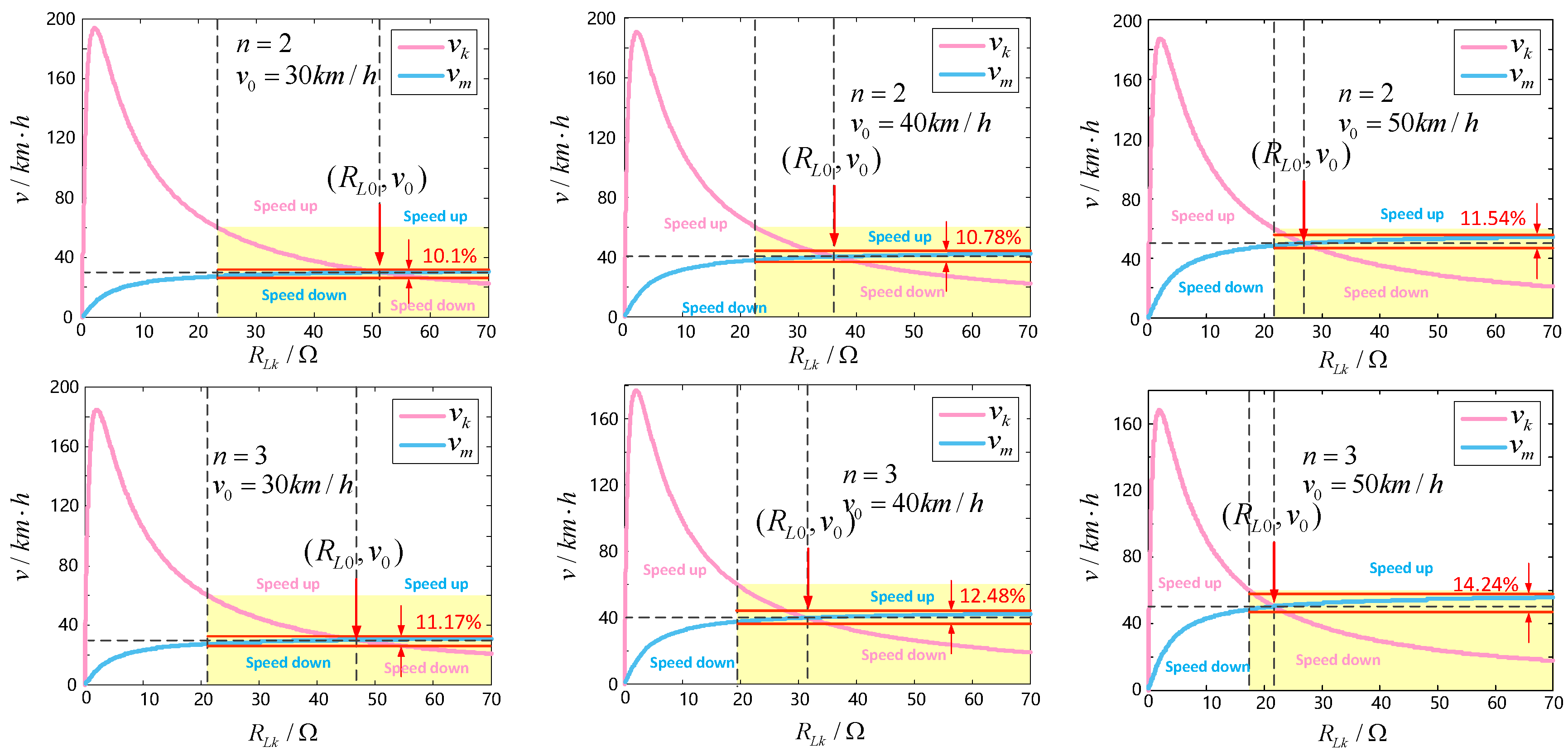
Figure 7 shows the variation of
and
with
in the case where the number of charging EVs in the charging area are two and three, and the initial dynamic charging speeds are 30 km/h, 40 km/h, and 50 km/h, respectively.
Considering that the maximum dynamic charging speed of the EVs set in this paper is 60 km/h, the specified range of the vehicle speed variation is marked in yellow in
Figure 7. First, adjust
to the corresponding
, with n and the initial velocity
determined, as follows: when the kth car accelerates from the initial speed
,
is adjusted to the left side of
,
decreases accordingly; when the kth car decelerates from the initial speed
,
is adjusted to the right of
, and
increases accordingly. That is, when the kth car accelerates, the remaining cars have to sacrifice their charging speed in order to adapt to the kth car’s acceleration; when the kth car decelerates, the remaining cars can accelerate accordingly to shorten their charging time.
Name the percentage change in
as
. It is shown in
Figure 7 that when
is set to 30 km/h, 40 km/h, and 50 km/h, respectively, when n = 2,
is 10.1%, 10.78%, and 11.54%, respectively; when n = 3,
is 11.17%, 12.48%, and 14.24%, respectively. Meanwhile, the range of
is basically maintained between 20 km/h~60 km/h. Comparing with the range of
,
is very small, which means that
is basically maintained near
in the process of
adjustment. Videlicet, when a single EV performs an
adjustment according to the speed change, it will not affect the speed of the other EVs too much.
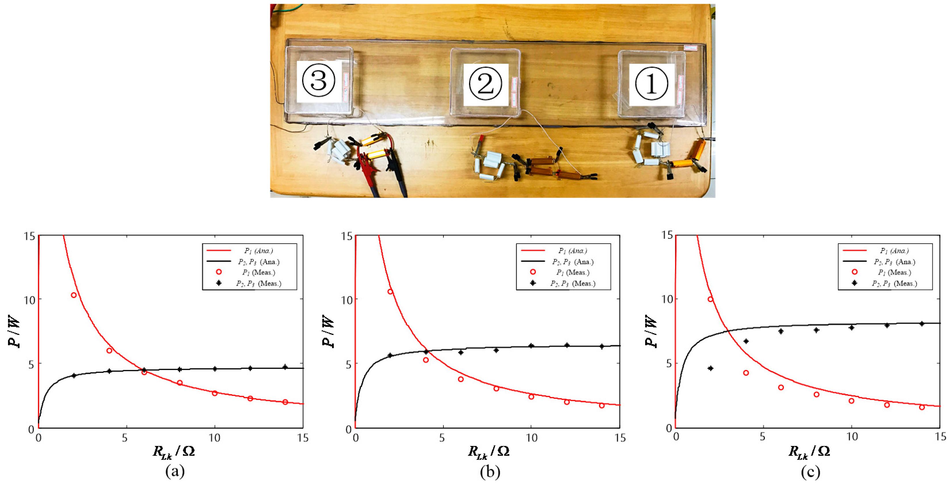
5. Experimental Verification
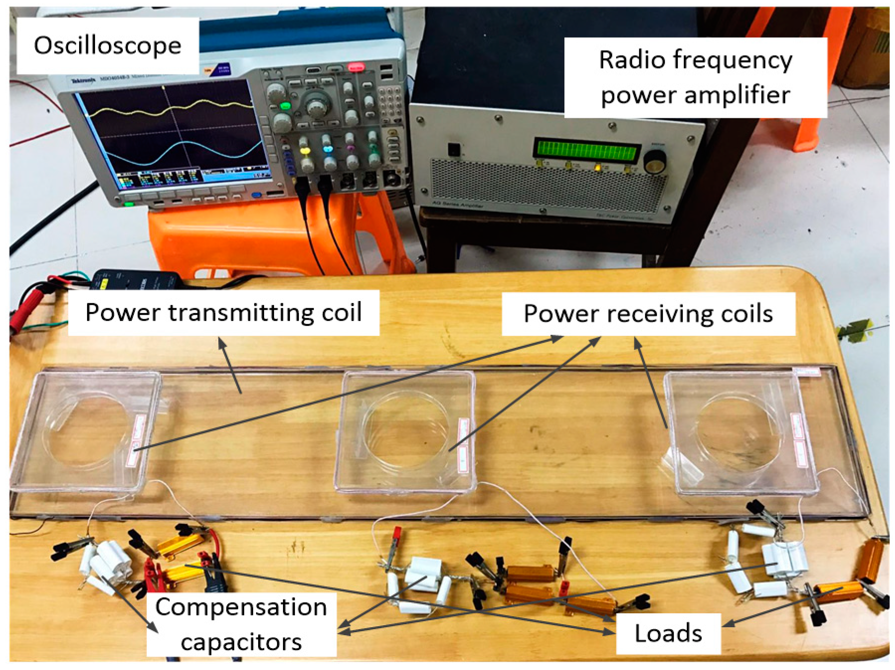
In order to verify the correctness of the above charging power control method based on the speed change, a corresponding scaled-down model is established as shown in
Figure 8. The length and width of the transmitting coil are 1 m and 0.2 m. The receiving coils are identical square coils with a side length of 0.15 m. The vertical distance between the transmitting coil and each receiving coil is 0.03 m.
As a result of the limitation of the actual conditions, we use the change of the critical compensation charging power corresponding to the load change instead of the change of the upper limit of the dynamic charging speed during the experiment. The range of charging power per load according to the velocity variation range in the experimental section is set as 0 W~9 W. Both the working frequency of the system and the resonant frequency between the transmitting and receiving coils are set as 85 kHz. The specific parameters of the model are tabulated in
Table 2.
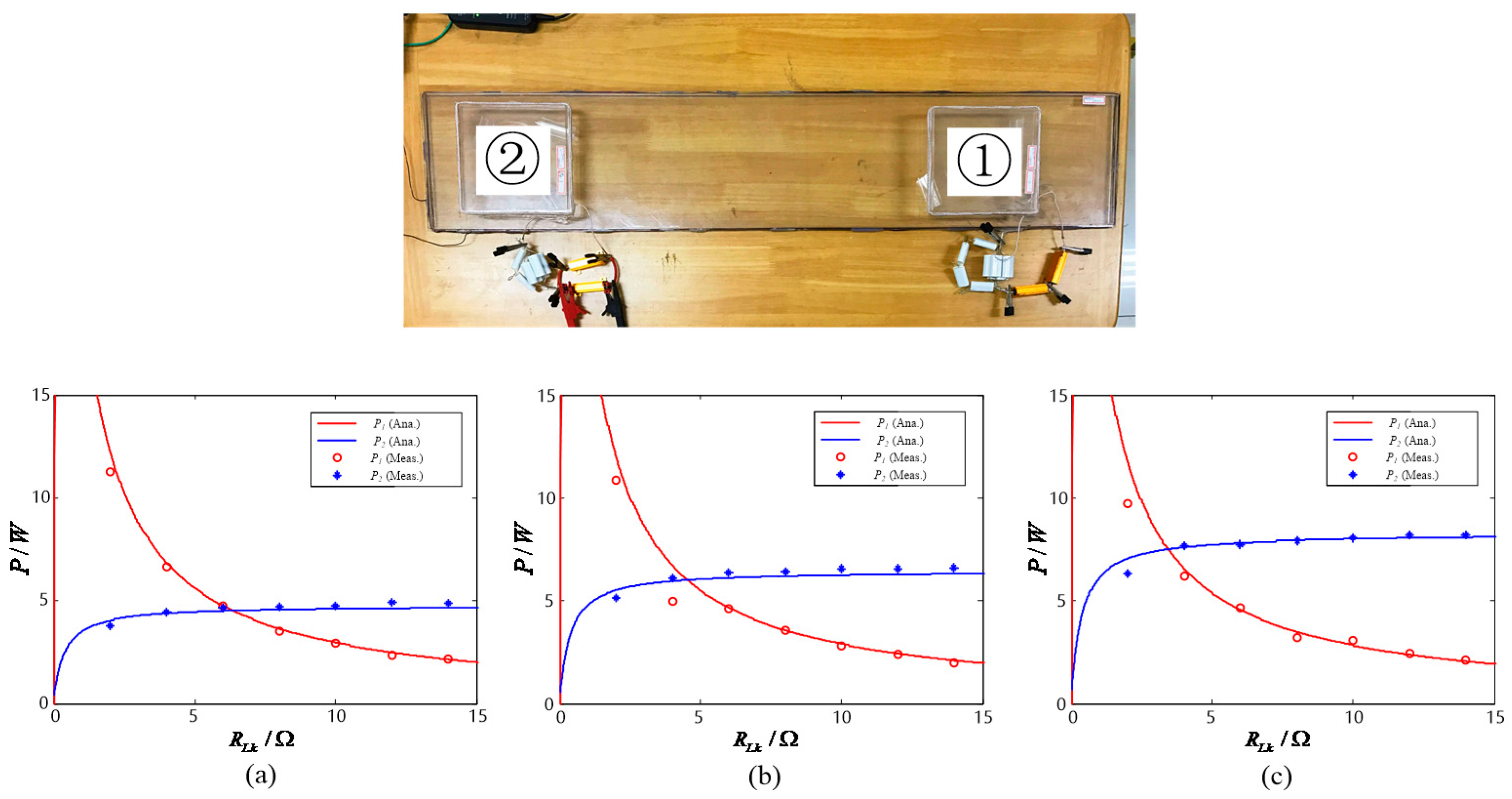
The charging power
corresponding to the initial speed
are set to 4.5 W, 6 W, and 7.5 W, respectively. In the experiment, we used a gold aluminum-clad resistor as the load. Although the accuracy of
obtained by the theoretical calculation is high, the resistor cannot achieve the same accuracy in the actual experiments, so the theoretical calculation value is approximated to one decimal place after the decimal point. When n = 2, the corresponding critical load resistance
calculated by Equation (6) are 6.373 Ω, 4.542 Ω, and 3.437 Ω (simplified to 6.4 Ω, 4.5, Ω, and 3.4 Ω in the experiment.). Let
constantly equal
, when
varies between 0 and 15 Ω, the charging power curves of 1 and 2 are shown in
Figure 9. When n = 3, the corresponding critical load resistance
calculated by Equation (6) is 5.972 Ω, 4.124 Ω, and 2.997 Ω (simplified to 6 Ω, 4 Ω, and 3 Ω in the experiment.). Let
and
constantly equal
, when
varies between 0 and 15 Ω, the charging power curves of one, two, and three are as shown in
Figure 10.
It can be seen from
Figure 9 and
Figure 10 that the experimental results are basically consistent with the simulation results. Set the maximum charging power to 9 W, it can be seen from
Figure 9 that when n = 2 and
is 4.5 W, 6 W, and 7.5 W, respectively, during the change of
, the receiving power variation range of load one is basically around 2 W~9 W, and the receiving power variation percentage of load two is are 9.09%, 9.45%, and 9.83%, respectively; it can be seen from
Figure 10 that when n = 3 and
is 4.5 W, 6 W, and 7.5 W, respectively, during the change of
, the receiving power variation range of load one is basically around 1.8 W~9 W, and the receiving power variation percentage of load two and load three are 9.56%, 10.17%, and 10.95%, respectively. The experimental conclusion is basically consistent with the theoretical analysis. From the experimental results, we can see that after setting
according to n and
,
can be changed within a large range by adjusting
, while the charging power of the remaining loads can be kept at a relatively stable level. In other words, by adopting the power control method proposed in this paper, a single EV can perform variable-speed dynamic wireless charging within a prescribed speed range, without affecting the charging state and effect of the remaining vehicles, while satisfying the self-charging demand only by adjusting its own equivalent load resistance, thereby improving the flexibility of the DWPT charging process.


