Self-Sustained Turn-Off Oscillation of SiC MOSFETs: Origin, Instability Analysis, and Prevention


Abstract
:1. Introduction
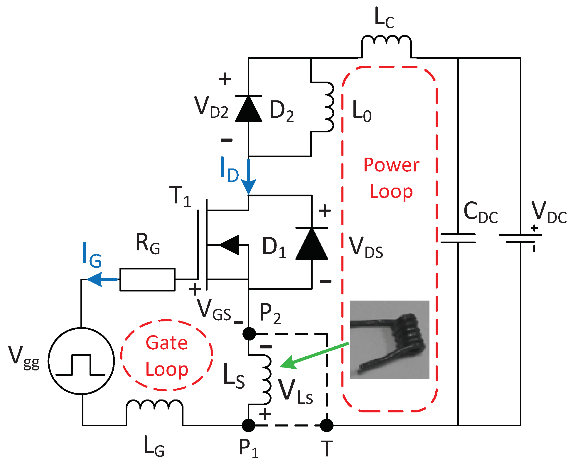
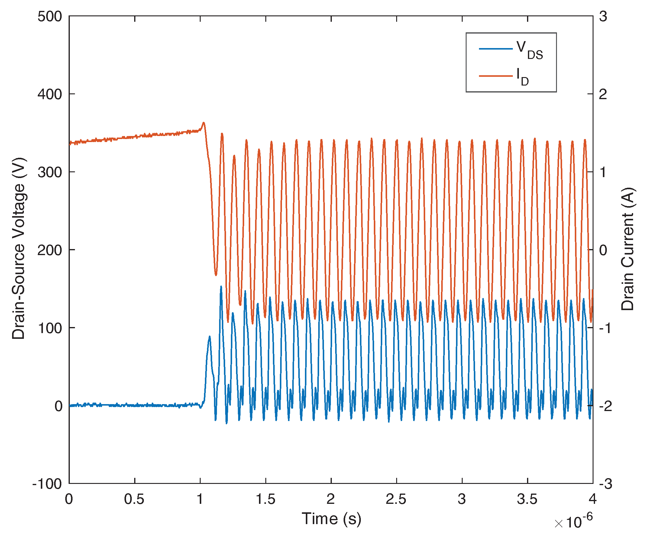
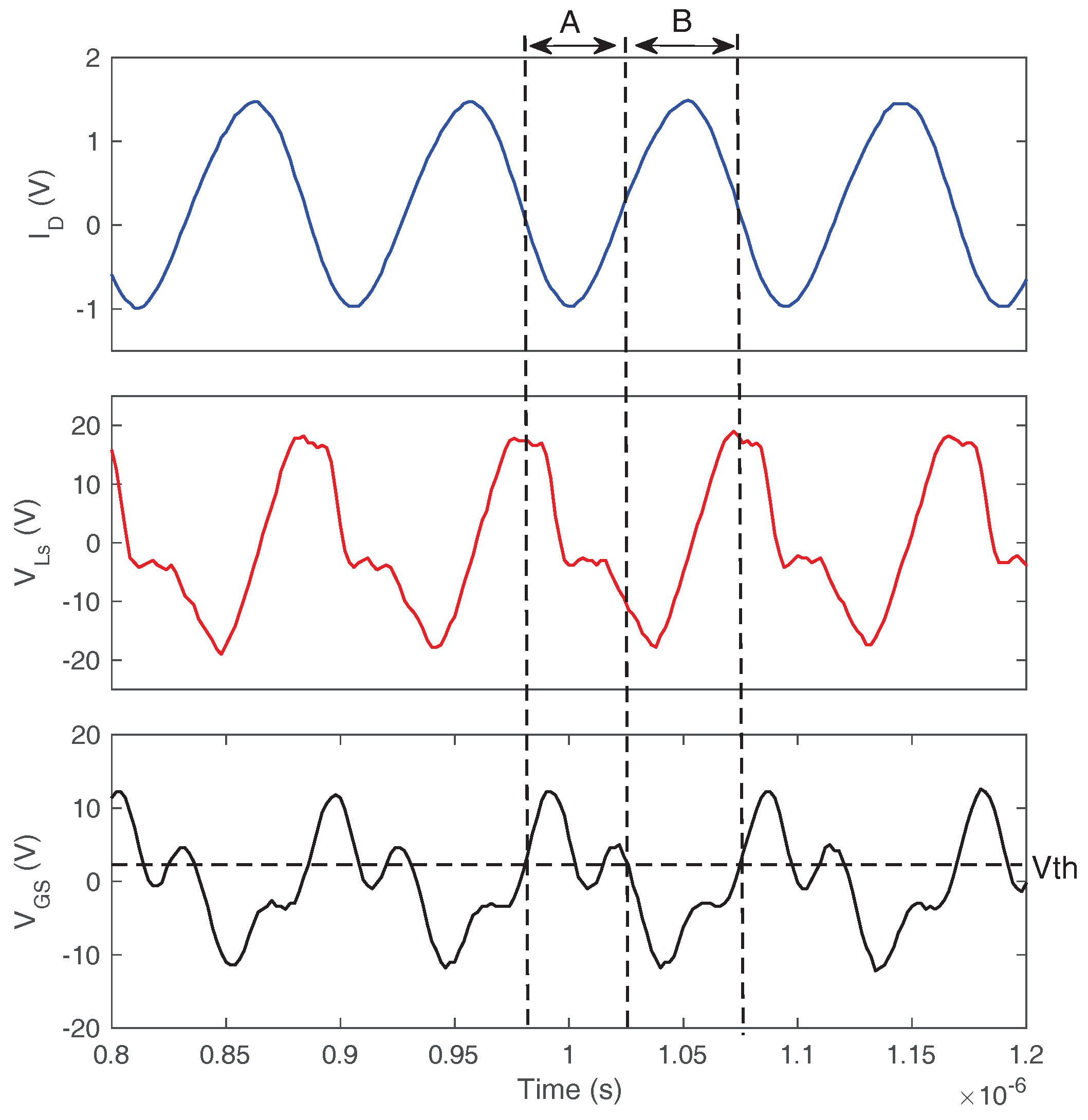
2. Experimental Identification
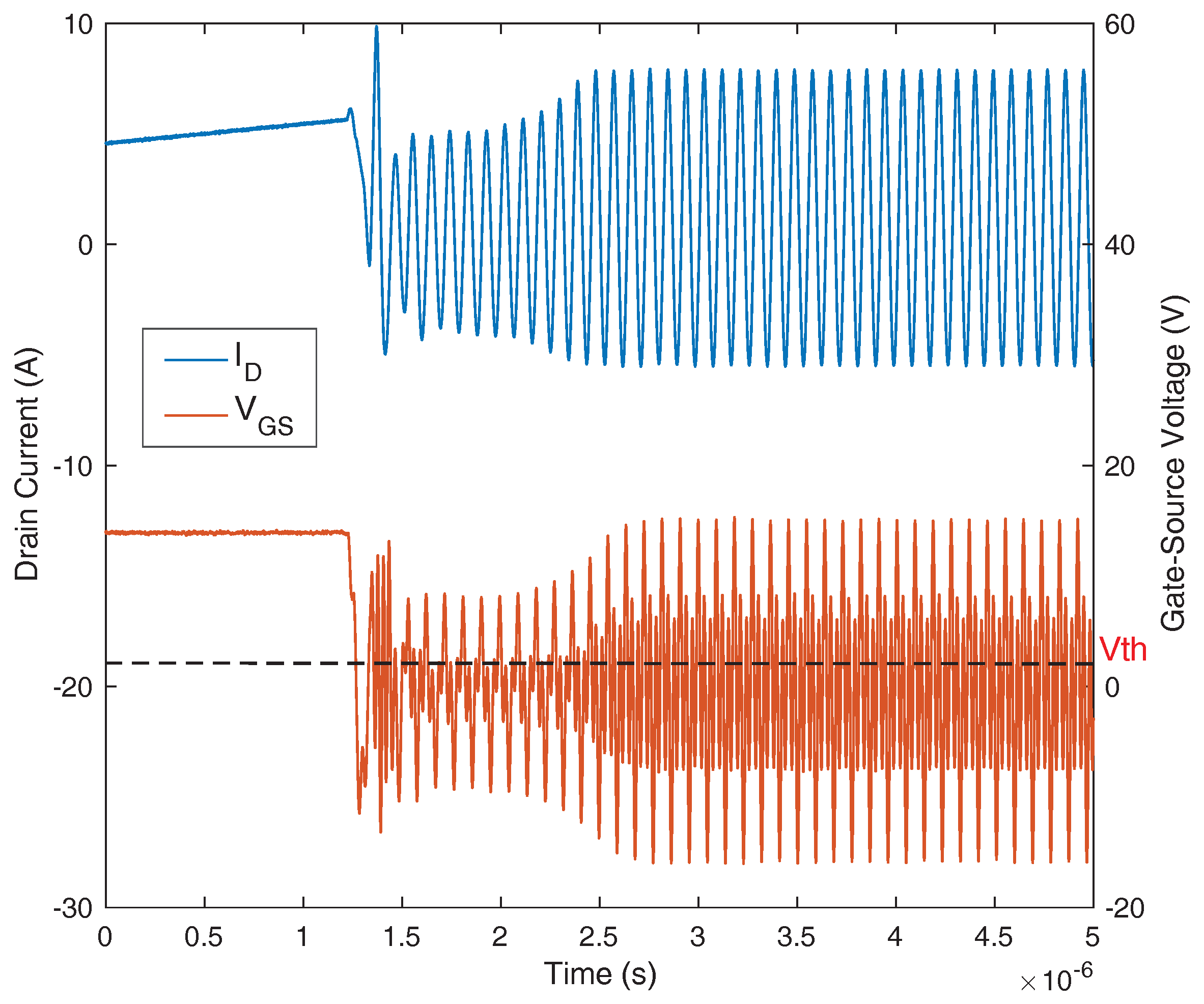
2.1. The Type I Self-Sustained Oscillation
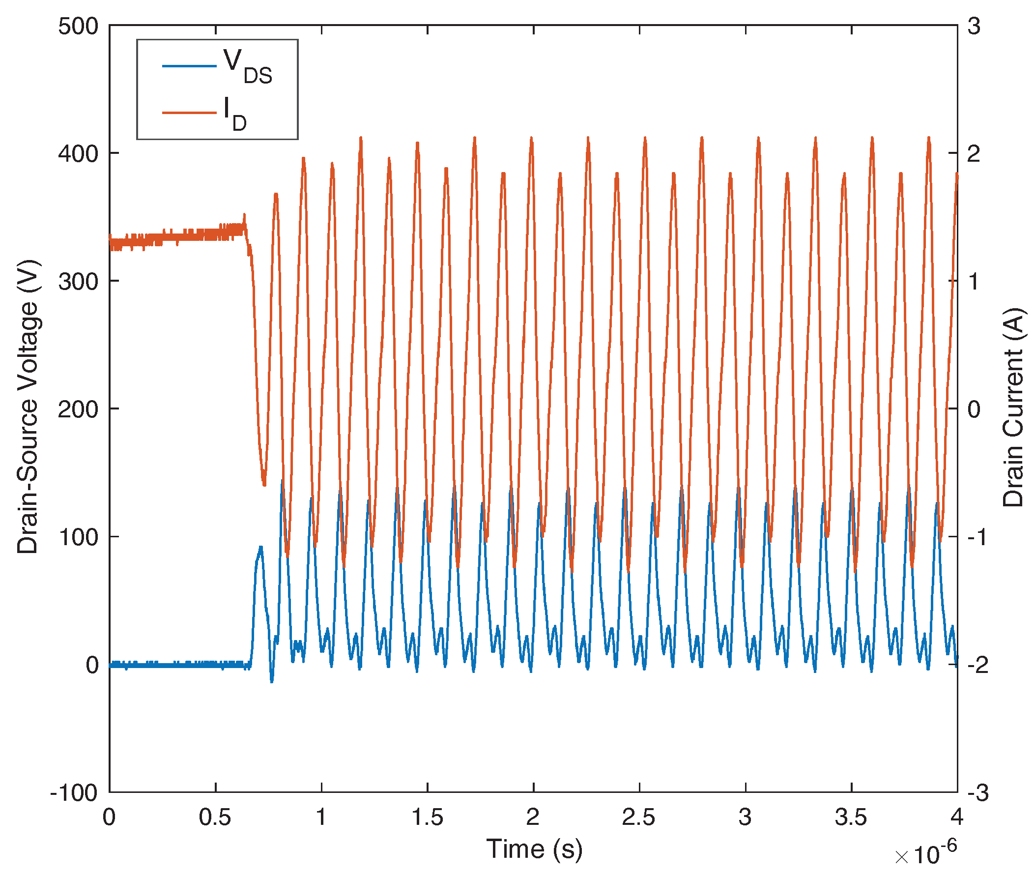
2.2. Type II Self-Sustained Oscillation
2.3. The Impact of on Self-Sustained Oscillation
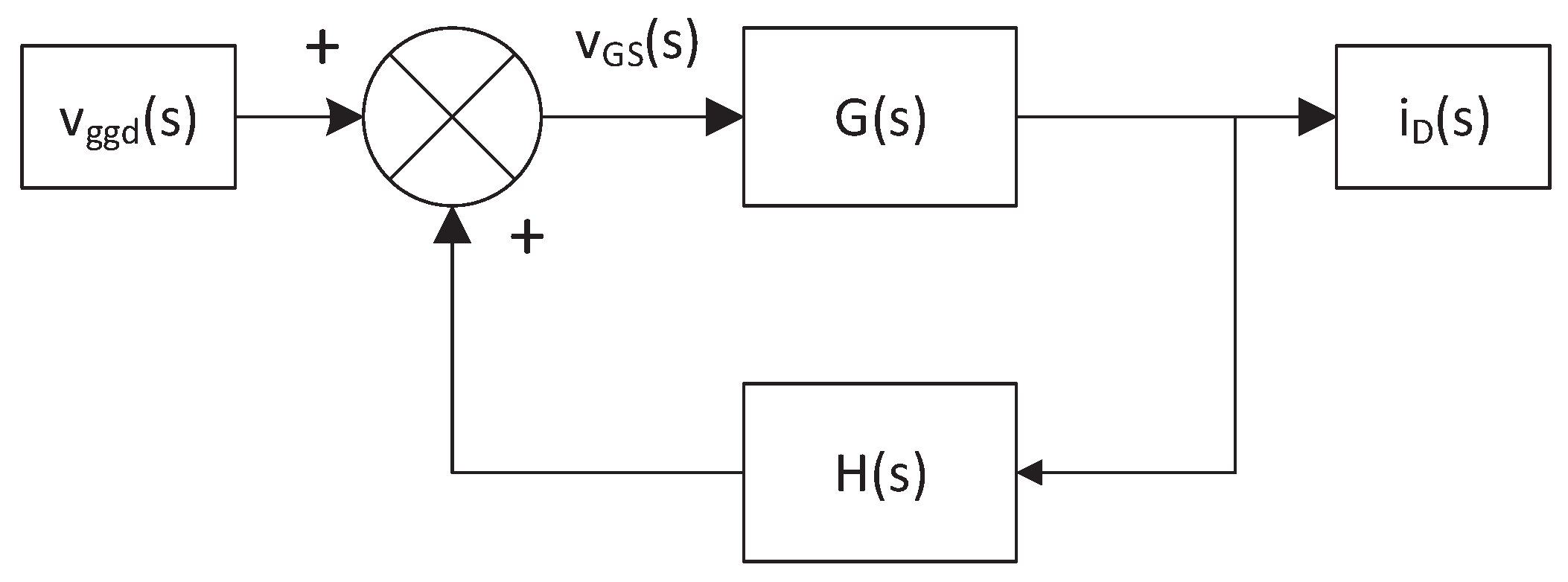
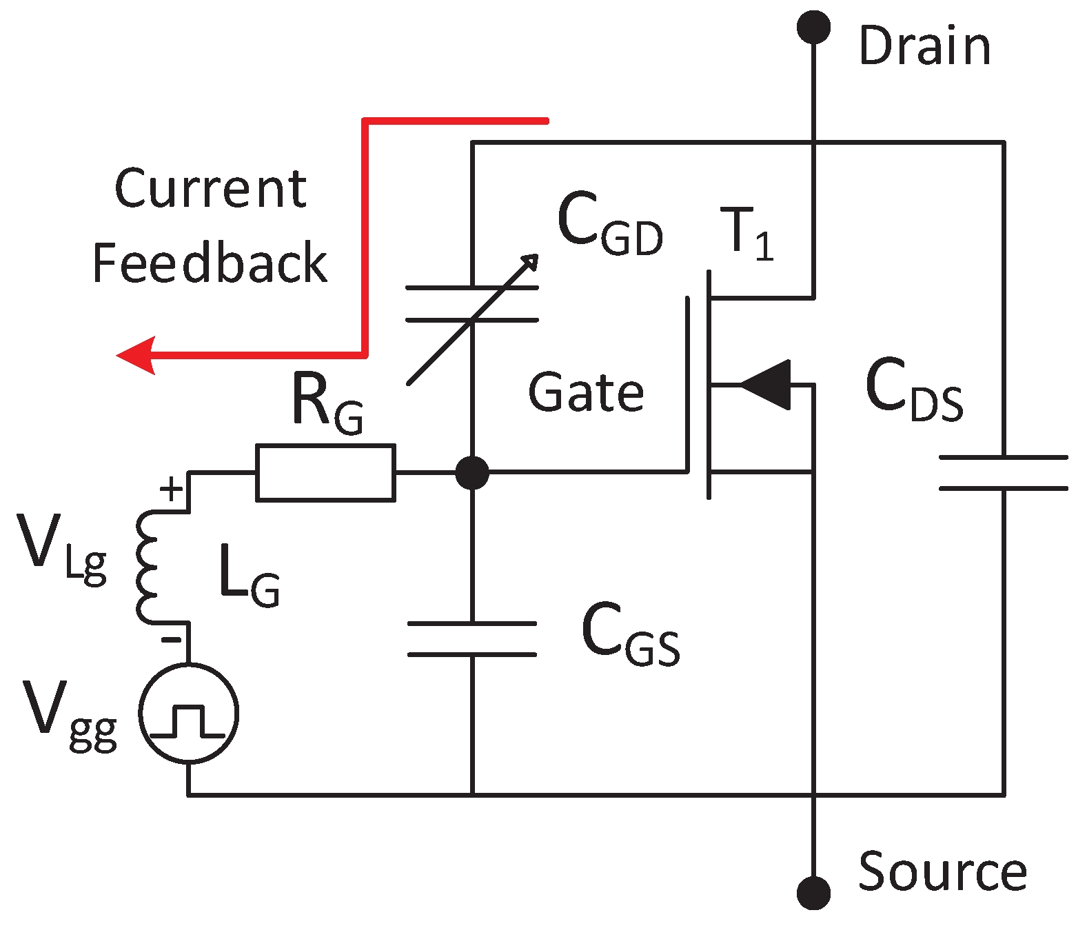
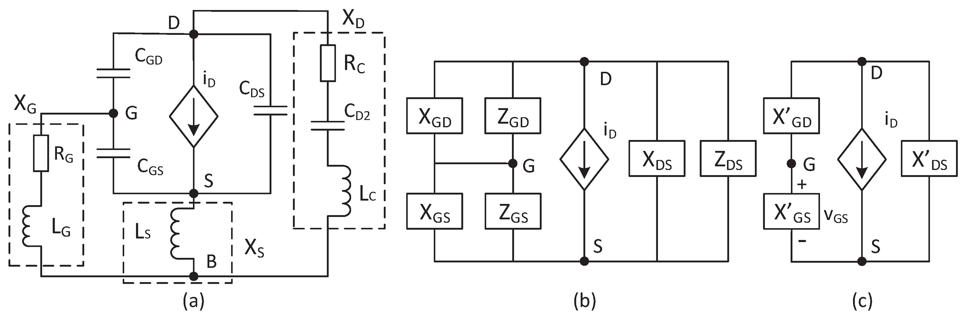
3. The Small-Signal Ac Model
4. The Analysis of Parametric Sensitivity on the Oscillatory Instability
4.1. The Parametric Sensitivity of the Type I Oscillation
4.2. The Parametric Sensitivity of the Type II Oscillation
5. Oscillation Prevention
- (1)
- Reducing the inductance : Since voltage on the is the major driving force of type I oscillations, the reduction of can greatly reduce and suppress type I oscillations.
- (2)
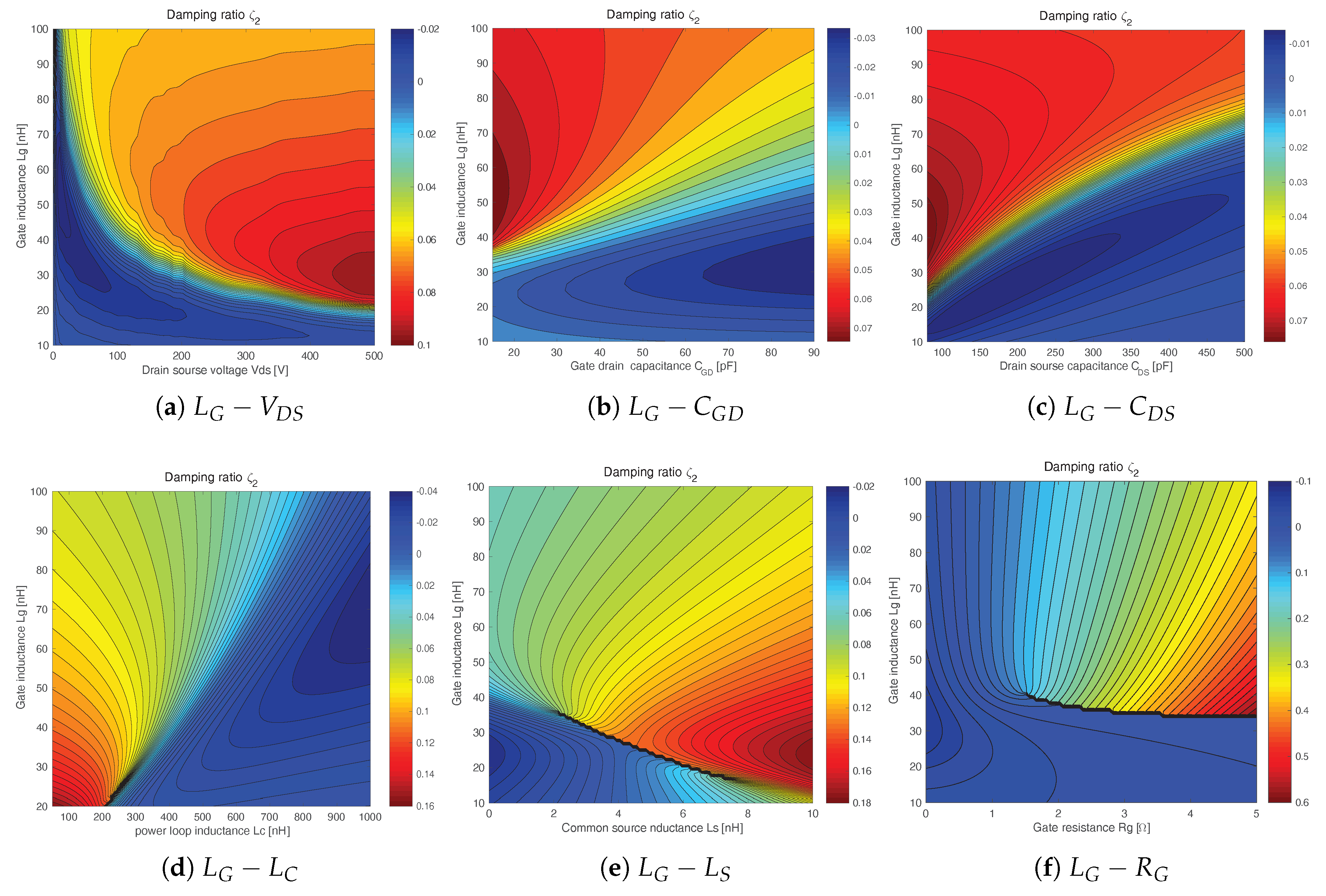
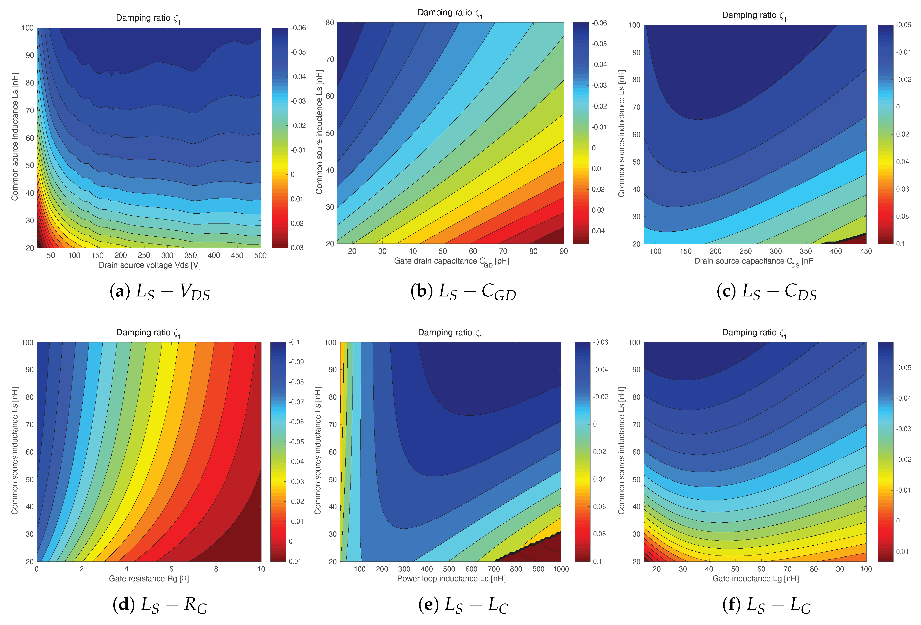
- Reducing the inductance : As shown in Figure 13e, the damping ratio significantly increases with the reduction of . can greatly lose its driving force when is small enough. Therefore, the reduction of is a very effective way to suppress type I oscillations.
- (3)
- Increasing the gate resistance : As shown in the Figure 13d, the damping ratio greatly increases with the raise of . Increasing is an obvious choice to avoid the self-sustained oscillation.
- (1)
- Reducing the inductance : With the reduction of , the instable region significantly compresses, as shown in Figure 14d. When is small enough, the type II oscillation can be eliminated.
- (2)
- Optimizing the gate inductance : The gate inductance has a great impact on type II oscillations. Many researches on the gate driver design claim that the gate driver should be very close to the MOSFET to avoid oscillations induced by the large [15,16]. Reducing is supposed to be the primary way to suppress the switching oscillation [8]. However, in this study, the analyses presented in Figure 14a,d reveal that the reduction of does not necessarily suppress type II oscillations. Its influence greatly depends on the operating condition, which is determined by parameters like and . Therefore, to suppress a type II oscillation, the value should be carefully chosen based on the operating condition.
- (3)
- Increasing the gate resistance : As shown in Figure 14f, the gate resistance has a very strong damping effect on the type II oscillation. Few ohms of are able to completely suppress the oscillation.
- (4)
- Increasing the supply voltage : Since the oscillation is biased by the supply voltage , the increase of can elevate the central tendency of the oscillation. As shown Figure 14a, with a high , a type II oscillation can be suppressed.
6. Experimental Validation
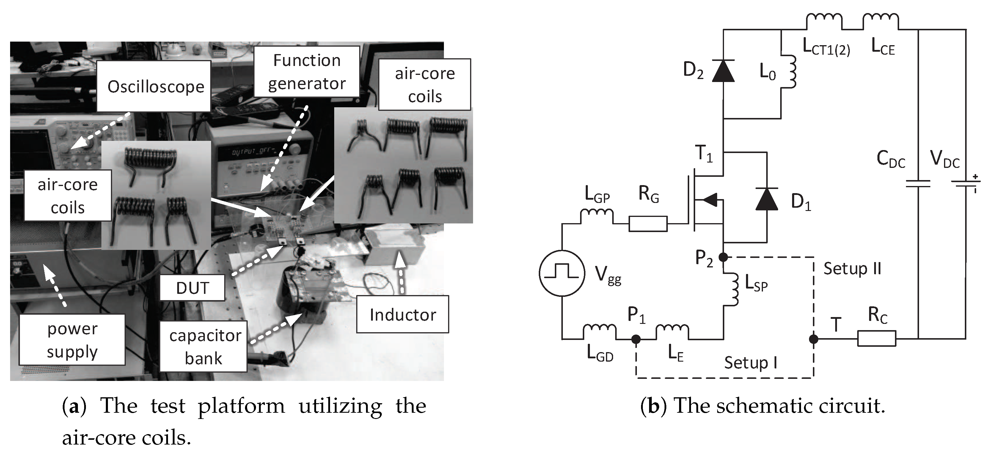
6.1. Experiment Setup
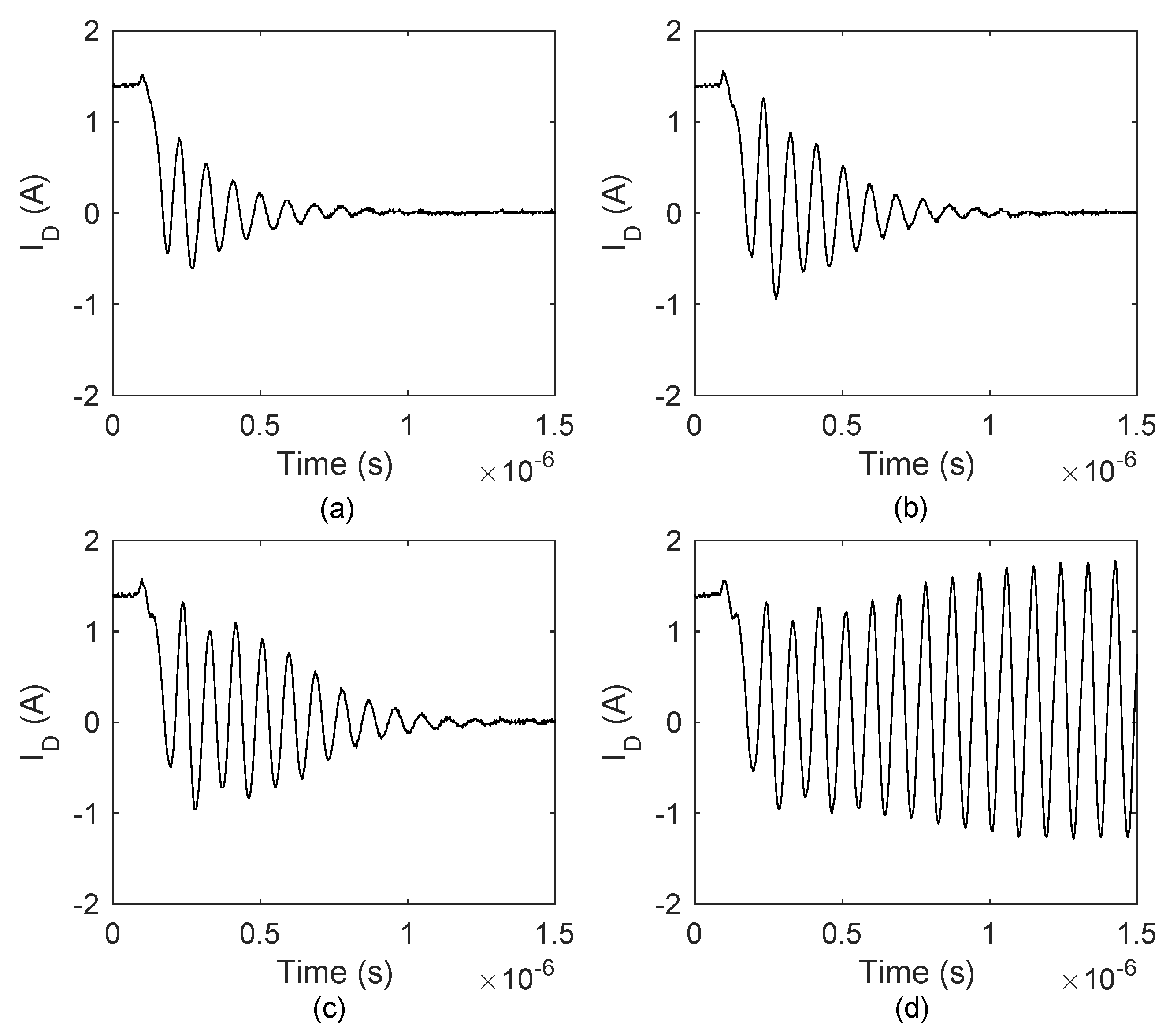
6.2. Experiment Results
6.2.1. Type I Oscillation
6.2.2. Type II Oscillation
7. Conclusions
Author Contributions
Funding
Conflicts of Interest
Appendix A
References
- Palmour, J.; Cheng, L.; Pala, V.; Brunt, E.; Lichtenwalner, D.; Wang, G.Y.; Richmond, J.; O’Loughlin, M.; Ryu, S.; Allen, S.; et al. Silicon carbide power MOSFETs: Breakthrough performance from 900 V up to 15 kV. In Proceedings of the 2014 IEEE 26th International Symposium on Power Semiconductor Devices & IC’s (ISPSD), Waikoloa, HI, USA, 15–19 June 2014; pp. 79–82. [Google Scholar]
- Biela, J.; Schweizer, M.; Waffler, S.; Kolar, J.W. SiC versus Si—Evaluation of potentials for performance improvement of inverter and DC–DC converter systems by SiC power semiconductors. IEEE Trans. Ind. Electron. 2011, 58, 2872–2882. [Google Scholar] [CrossRef]
- Lemmon, A.; Mazzola, M.; Gafford, J. Instability in Half-Bridge Circuits Switched with Wide Band-Gap Transistors. IEEE Trans. Power Electron. 2014, 29, 2380–2392. [Google Scholar] [CrossRef]
- Lemmon, A.; Mazzola, M.; Gafford, J.; Parker, C. Stability Considerations for Silicon Carbide Field-Effect Transistors. IEEE Trans. Power Electron. 2013, 28, 4453–4459. [Google Scholar] [CrossRef]
- Wang, K.; Yang, X.; Wang, L.; Jain, P. Instability Analysis and Oscillation Suppression of Enhancement-Mode GaN Devices in Half-Bridge Circuits. IEEE Trans. Power Electron. 2018, 33, 1585–1596. [Google Scholar] [CrossRef]
- Sugihara, Y.; Nanamori, K.; Ishiwaki, S.; Hayashi, Y.; Aikawa, K.; Umetani, K.; Hiraki, E.; Yamamoto, M. Analytical investigation on design instruction to avoid oscillatory false triggering of fast switching SiC-MOSFETs. In Proceedings of the IEEE Energy Conversion Congress and Exposition (ECCE), Cincinnati, OH, USA, 1–5 October 2017; pp. 5113–5118. [Google Scholar]
- Zhang, W.; Zhang, Z.; Wang, F.; Costinett, D.; Tolbert, L.; Blalock, B. Common source inductance introduced self-turn-on in MOSFET turn-off transient. In Proceedings of the 2017 IEEE Applied Power Electronics Conference and Exposition (APEC), Tampa, FL, USA, 26–30 March 2017; pp. 837–842. [Google Scholar]
- Chen, Z.; Boroyevich, D.; Burgos, R. Experimental parametric study of the parasitic inductance influence on MOSFET switching characteristics. In Proceedings of the 2010 International IEEE Power Electronics Conference (IPEC), Sapporo, Japan, 21–24 June 2010; pp. 164–169. [Google Scholar]
- Miao, Z.; Mao, Y.; Ngo, K.; Kim, W. Package influence on the simulated performance of 1.2 kV SiC modules. In Proceedings of the 2015 IEEE 3rd Workshop on Wide Bandgap Power Devices and Applications (WiPDA), Blacksburg, VA, USA, 2–4 November 2015; pp. 306–311. [Google Scholar]
- Liu, T.; Ning, R.; Wong, T.T.Y.; Shen, Z.J. Modeling and Analysis of SiC MOSFET Switching Oscillations. IEEE J. Emerg. Sel. Top. Power Electron. 2017, 4, 747–756. [Google Scholar] [CrossRef]
- Milady, S. Spatial and Temporal Instabilities in High Voltage Power Devices. Ph.D. Thesis, University of Bremen, Bremen, Germany, 2010. [Google Scholar]
- Gopal, M. Control Systems: Principles and Design; Tata McGraw-Hill Education: New York, NY, USA, 2002. [Google Scholar]
- Yang, B.; Zhang, J. Effect and utilization of common source inductance in synchronous rectification. In Proceedings of the Twentieth Annual IEEE Applied Power Electronics Conference and Exposition (APEC 2005), Austin, TX, USA, 6–10 March 2005; Volume 3, pp. 1407–1411. [Google Scholar]
- Xiao, Y.; Shah, H.; Chow, T.; Gutmann, R. Analytical modeling and experimental evaluation of interconnect parasitic inductance on MOSFET switching characteristics. In Proceedings of the IEEE Applied Power Electronics Conference and Exposition, Anaheim, CA, USA, 22–26 February 2004; Volume 1, pp. 516–521. [Google Scholar]
- Bob, C. Application Considerations for Silicon Carbide MOSFETs; Cree Inc.: Durham, NC, USA, 2011; Application Note. [Google Scholar]
- Balogh, L. Design and Application Guide for High Speed MOSFET Gate Drive Circuits; Texas Instruments/Unitrode Corporation: Dallas, TX, USA, 2002. [Google Scholar]
- Han, D.; Lee, W.; Noppakunkajorn, J.; Sarlioglu, B. Investigating the influence of interconnection parasitic inductance on the performance of SiC based DC-DC converters in hybrid vehicles. In Proceedings of the IEEE Transportation Electrification Conference and Expo (ITEC), Dearborn, MI, USA, 15–18 June 2014; pp. 1–7. [Google Scholar]
- Bryant, A.T.; Kang, X.; Santi, E.; Palmer, P.R.; Hudgins, J.L. Two-step parameter extraction procedure with formal optimization for physics-based circuit simulator IGBT and p-i-n diode models. IEEE Trans. Power Electron. 2006, 21, 295–309. [Google Scholar] [CrossRef]
- Knight, D.W. An Introduction to the Art of Solenoid Inductance Calculation with Emphasis on Radio-Frequency Applications. Available online: http://www.g3ynh.info/zdocs/magnetics/part_1.html (accessed on 10 March 2019).


| Parameter | Value | Parameter | Value |
|---|---|---|---|
| 0.1 S | 25 nH | ||
| 0.2 | 824 pF | ||
| 1 | 2000 pF | ||
| 0–40 nH | 25 pF | ||
| 400 nH | 170 pF |
| Parameter | Value | Parameter | Value |
|---|---|---|---|
| 0.1 S | 2 nF | ||
| 0.2 | 246 pF | ||
| 824 pF | 37 pF | ||
| 7 nH | 8 nH | ||
| 150 nH | 200 nH | ||
| 19, 34, 46, 60, 73, 90 nH | |||
| 110, 170, 260, 330, 450 nH | |||
| 26 nH | 41 nH | 53 nH | 67 nH | 80 nH | 97 nH | ||
|---|---|---|---|---|---|---|---|
| 1.5 | −0.019 (9) | −0.059 (inf) | −0.073 (inf) | −0.082 (inf) | −0.087 (inf) | −0.091 (inf) | |
| 2 | 0.007 (8) | −0.043 (12) | −0.059 (inf) | −0.070 (inf) | −0.076 (inf) | −0.081 (inf) | |
| 3 | 0.024 (8) | −0.017 (8) | −0.035 (9) | −0.049 (11) | −0.057(inf) | −0.063 (inf) | |
| 3.6 | 0.030 (6) | −0.005 (7) | −0.023 (8) | −0.037 (9) | −0.046 (10) | −0.053 (inf) | |
| 5 | 0.033 (6) | 0.014 (6) | −0.001 (6) | −0.014 (6) | −0.023 (7) | −0.031 (7) | |
| 26 nH | 41 nH | 53 nH | 67 nH | 80 nH | 97 nH | ||
|---|---|---|---|---|---|---|---|
| 150 nH | −0.026 (6) | −0.033 (6) | −0.035 (7) | −0.037 (7) | −0.038 (8) | −0.039 (8) | |
| 260 nH | −0.028 (9) | −0.046 (10) | −0.053 (12) | −0.058 (inf) | −0.061 (inf) | −0.063 (inf) | |
| 320 nH | −0.021 (9) | −0.048 (15) | −0.058 (inf) | −0.065 (inf) | −0.069 (inf) | −0.072 (inf) | |
| 410 nH | 0.007 (8) | −0.043 (12) | −0.059 (inf) | −0.070 (inf) | −0.076 (inf) | −0.081 (inf) | |
| 22 nH | 41 nH | 56 nH | 68 nH | 82 nH | ||
|---|---|---|---|---|---|---|
| 200 nH | 0.020 (5) | 0.153 (5) | 0.137 (5) | 0.127 (7) | 0.118 (8) | |
| 310 nH | −0.003 (inf) | 0.125 (6) | 0.119 (6) | 0.114 (6) | 0.108 (6) | |
| 460 nH | −0.006 (inf) | −0.008 (inf) | 0.021 (8) | 0.072 (6) | 0.086 (5) | |
| 530 nH | −0.006 (inf) | −0.013 (inf) | −0.003 (inf) | 0.026 (8) | 0.065 (5) | |
| 650 nH | −0.005 (20) | −0.015 (inf) | −0.018 (inf) | −0.011 (inf) | 0.011 (6) | |
| 22 nH | 41 nH | 56 nH | 68 nH | 82 nH | ||
|---|---|---|---|---|---|---|
| 50 V | −0.006 (inf) | −0.008 (inf) | 0.021 (8) | 0.072 (6) | 0.086 (5) | |
| 100 V | −0.007 (inf) | 0.017 (7) | 0.094 (7) | 0.099 (7) | 0.097 (7) | |
| 200 V | −0.003 (inf) | 0.110 (5) | 0.114 (4) | 0.109 (6) | 0.103 (6) | |
| 300 V | 0.007 (5) | 0.130 (4) | 0.121 (5) | 0.114 (5) | 0.106 (4) | |
| 22 nH | 41 nH | 56 nH | 68 nH | 82 nH | ||
|---|---|---|---|---|---|---|
| 1.5 | −0.006 (inf) | −0.008 (inf) | 0.021 (8) | 0.072 (6) | 0.086 (5) | |
| 2 | −0.001 (11) | 0.002 (7) | 0.033 (8) | 0.123 (4) | 0.127 (4) | |
| 3 | 0.007 (6) | 0.014 (6) | 0.034 (7) | 0.234 (7) | 0.212 (5) | |
© 2019 by the authors. Licensee MDPI, Basel, Switzerland. This article is an open access article distributed under the terms and conditions of the Creative Commons Attribution (CC BY) license (http://creativecommons.org/licenses/by/4.0/).
Share and Cite
Xue, P.; Maresca, L.; Riccio, M.; Breglio, G.; Irace, A. Self-Sustained Turn-Off Oscillation of SiC MOSFETs: Origin, Instability Analysis, and Prevention. Energies 2019, 12, 2211. https://doi.org/10.3390/en12112211
Xue P, Maresca L, Riccio M, Breglio G, Irace A. Self-Sustained Turn-Off Oscillation of SiC MOSFETs: Origin, Instability Analysis, and Prevention. Energies. 2019; 12(11):2211. https://doi.org/10.3390/en12112211
Chicago/Turabian StyleXue, Peng, Luca Maresca, Michele Riccio, Giovanni Breglio, and Andrea Irace. 2019. "Self-Sustained Turn-Off Oscillation of SiC MOSFETs: Origin, Instability Analysis, and Prevention" Energies 12, no. 11: 2211. https://doi.org/10.3390/en12112211
APA StyleXue, P., Maresca, L., Riccio, M., Breglio, G., & Irace, A. (2019). Self-Sustained Turn-Off Oscillation of SiC MOSFETs: Origin, Instability Analysis, and Prevention. Energies, 12(11), 2211. https://doi.org/10.3390/en12112211