Article

Improving Performance of Far Users in Cognitive Radio: Exploiting NOMA and Wireless Power Transfer

by
Minh-Sang Van Nguyen
1,
Dinh-Thuan Do
2,* and
Miroslav Voznak
3
1
Faculty of Electronics Technology, Industrial University of Ho Chi Minh City (IUH), Ho Chi Minh City 700000, Vietnam
2
Wireless Communications Research Group, Faculty of Electrical and Electronics Engineering, Ton Duc Thang University, Ho Chi Minh City 700000, Vietnam
3
Faculty of Electrical Engineeringg and Computer Science, VSB—Technical University of Ostrava, 17. listopadu 2172/15, 708 00 Ostrava, Czech Republic
*
Author to whom correspondence should be addressed.
Energies 2019, 12(11), 2206; https://doi.org/10.3390/en12112206
Submission received: 11 April 2019 / Revised: 5 June 2019 / Accepted: 5 June 2019 / Published: 10 June 2019
(This article belongs to the Special Issue Future Wireless Power Transfer and Communications)

Abstract

:
In this paper, we examine non-orthogonal multiple access (NOMA) and relay selection strategy to benefit extra advantage from traditional cognitive radio (CR) relaying systems. The most important requirement to prolong lifetime of such network is employing energy harvesting in the relay to address network with limited power constraint. In particular, we study such energy harvesting CR-NOMA using amplify-and-forward (AF) scheme to improve performance far NOMA users. To further address such problem, two schemes are investigated in term of number of selected relays. To further examine system performance, the outage performance needs to be studied for such wireless powered CR-NOMA network over Rayleigh channels. The accurate expressions for the outage probability are derived to perform outage comparison of primary network and secondary network. The analytical results show clearly that position of these nodes, transmit signal to noise ratio (SNR) and power allocation coefficients result in varying outage performance. As main observation, performance gap between primary and secondary destination is decided by both power allocation factors and selection mode of single relay or multiple relays. Numerical studies were conducted to verify our derivations.

1. Introduction

This is an era of explosive growth of mobile devices and broadband wireless services. It requires deployment of advanced communication techniques to meet demand of huge connections and enhance the spectral efficiency. The non-orthogonal multiple access (NOMA) and cognitive radio (CR) are considered to be two of the most effective methods to achieve spectral efficiency as in [1,2]. After the combination of both NOMA and CR definitions, the authors studied the spectrum efficiency and secrecy energy efficiency in the proposed CR-NOMA scheme as in [3]. Many other studies focus on facilitating the application of NOMA to CR and investigating the performance of CR with NOMA. In CR-NOMA, occasionally, the unlicensed secondary users (SU) can be served the same quality of service (QoS) conditions as the licensed primary users (PU). Therefore, the transfer energy distributed to the SU is limited by the immediate signal-to-interference-plus noise ratio (SINR) of the PU. This is the advantage of CR-NOMA compared to conventional CR systems. It can achieve higher spectral effect because both PU and SU can work well using the same spectrum at the same time.
Recent studies in [4,5,6] have used a number of transmission systems to form energy harvesting (EH) assisted cooperative networks. In [4], the authors used relays to benefit EH in the first time in collaborative communication. In [5,6], the authors introduced numerous system models to allocate energy to power constraint devices with assuming a EH model which is defined according to time allocated for EH and the amount of harvested energy known before transmission. However, because both the energy arrival time and the amount of energy harvested are random, the predefined EH model seems unsuitable. Therefore, the authors of [7,8] introduced some transmission approaches to enable EH in networks in terms of using the general EH configurations. In particular, co-channel interference contributes to increase harvested energy for relays because more sources feed energy to dedicated device [8]. Further research on some effects in relaying network, such as imperfect channel state information or relay selection mode, is presented in [9,10,11].
In other trends of research, NOMA together with EH is one of the promising techniques that will help improve the number of served users who have limited power [12,13]. The important advantage of NOMA technology over traditional orthogonal multiple access (OMA) techniques is to allow multiple users to access the network simultaneously and at the same frequency by using non-orthogonal sources, such as different power levels or low density spreading codes. There have been many studies and discussions on the pros and cons of different NOMA schemes. Various NOMA system models have been applied and described. NOMA techniques have special advantages in non-orthogonality manner. They exhibit spectral efficiency, massive connectivity and low transmission latency regardless of the complexity of the interfering situation and the performance of the receiver. In [12], the implementation of NOMA in the CR transmission is examined and the performance of CR-NOMA is also described. The authors of [13] introduced NOMA based on the amplify and forward (AF) relaying procedure through Nakagami-m fading channels and it showed superiority to conventional NOMA. In [14], the collaborative EH NOMA protocol is introduced, in which the NOMA-strong users act as EH based relays to further assist the NOMA-weak users. In [15], the authors proposed closed-form expressions for total throughput and outage probability with static powers for different users as considering the uplink NOMA system.
Recent studies in [16,17,18] have demonstrated the superiority of the combination of CR and NOMA compared with CR with OMA for achieving a remarkable increase in spectrum efficiency. In addition, the NOMA techniques presented in [19,20,21] are extra solutions that contribute to improve spectrum access opportunities in CR network. We can improve the performance of SU and PU at the same time by designing a suitable cooperation model between CRs and NOMA as in [19,20,21]. Moreover, CRs’ energy efficiency (EE) with NOMA may be higher than that of CRs with OMA as interesting work in [22]. In [23], a general optimization algorithm is presented to solve the spectrum resource optimization problem for CR NOMA. Nevertheless many challenges need to be addressed for its extensive use [24,25,26]. If these challenges are not fully understood and solved, spectrum efficiency of CRs may be reduced or even the designed CR may not work. For example, due to the non-orthogonal nature of NOMA, system model includes the primary source and the secondary receiving nodes following Rayleigh distribution as in [26]. In such paper, an exact closed-form of the outage probability for each secondary destination is derived. They further provided asymptotic expressions related to the outage probability [26]. Despite the extensive and individual studies, there are not much related works focused on combining EH with CR-NOMA.
In fact, integrating EH into CR-NOMA is only at an early stage. Thus, it is of great importance to understand the challenges and benefits of EH to implement green communication in such CR-NOMA. Therefore, we conducted research and analyzed the outage probability and throughput performance in such system. We directly obtained the closed-form expressions of the outage probability by studying the signal to interference and noise ratios (SINRs) at users. Up to now, no research work has focused on the EH assisted CR-NOMA scheme by exploiting performance gap between primary destination and secondary destination. In this paper, we aim to fill this open problem. From the above analysis, outage performance gap exists in such CR NOMA network where NOMA and relay selection strategy are applied for primary and secondary networks.
The following is a summary of the main contributions of this study:
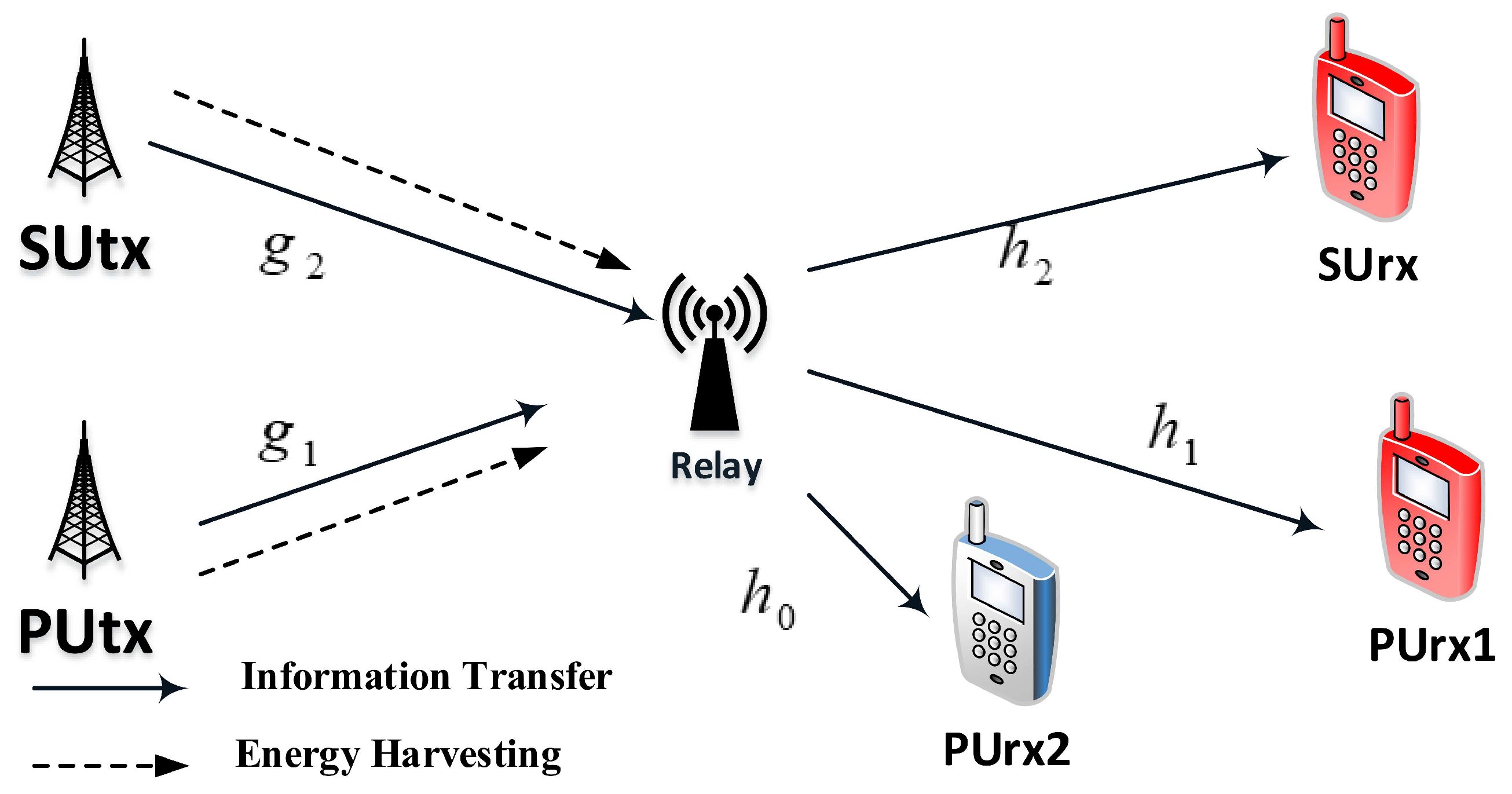
  • Reliable transmission of AF relaying scheme required in such CR-NOMA system with a common relay and EH policy was studied. This implementation of two schemes is designed to satisfy the users’ condition in terms of channel quality with respect to the more reliable transmitted information. We intend to analyze the system performance of EH assisted CR-NOMA networks through the Rayleigh fading channels.
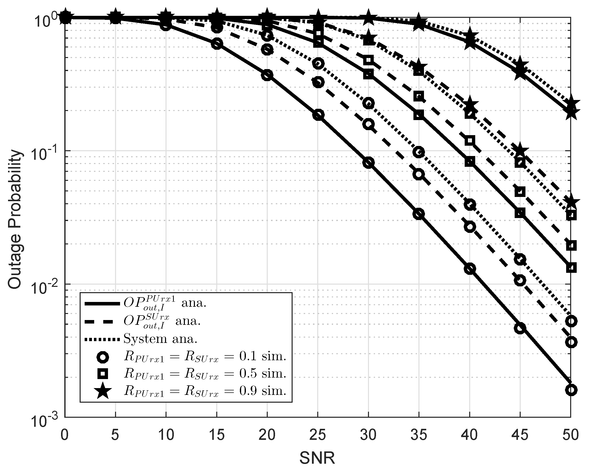
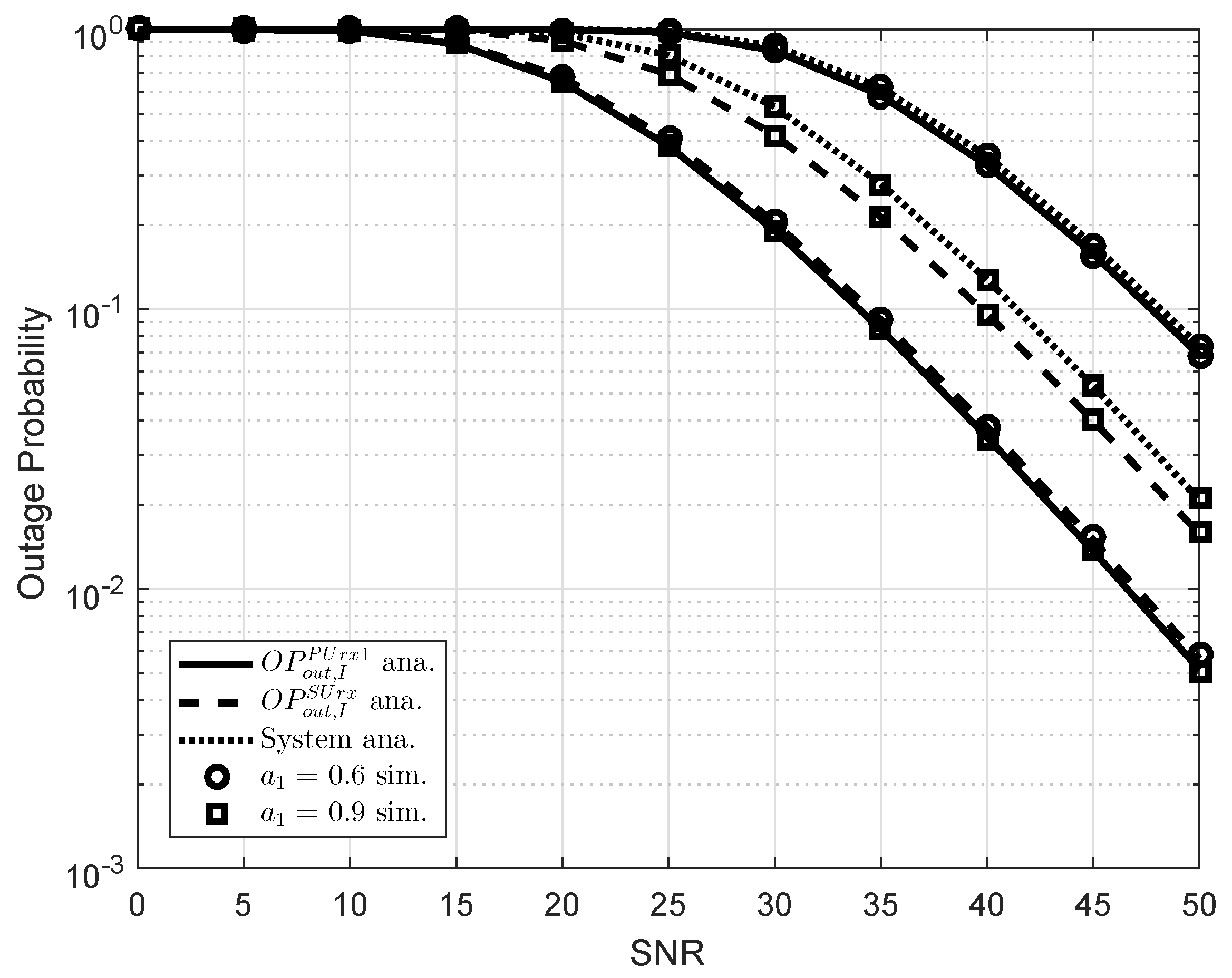
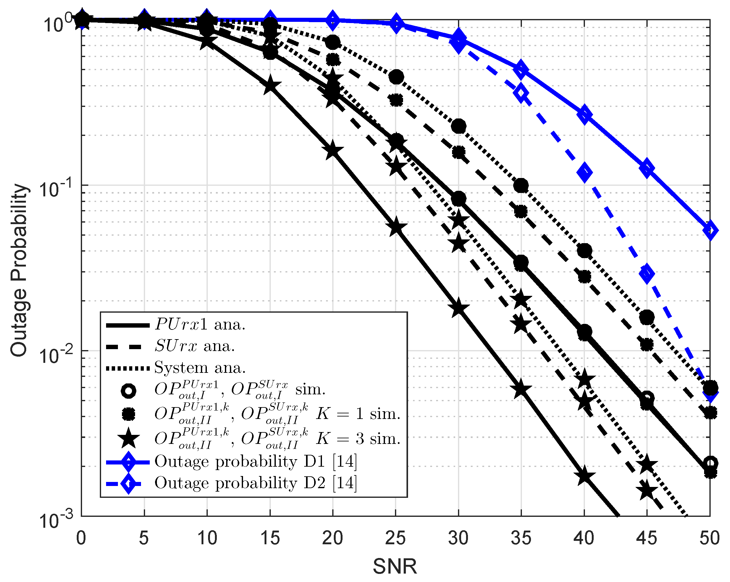
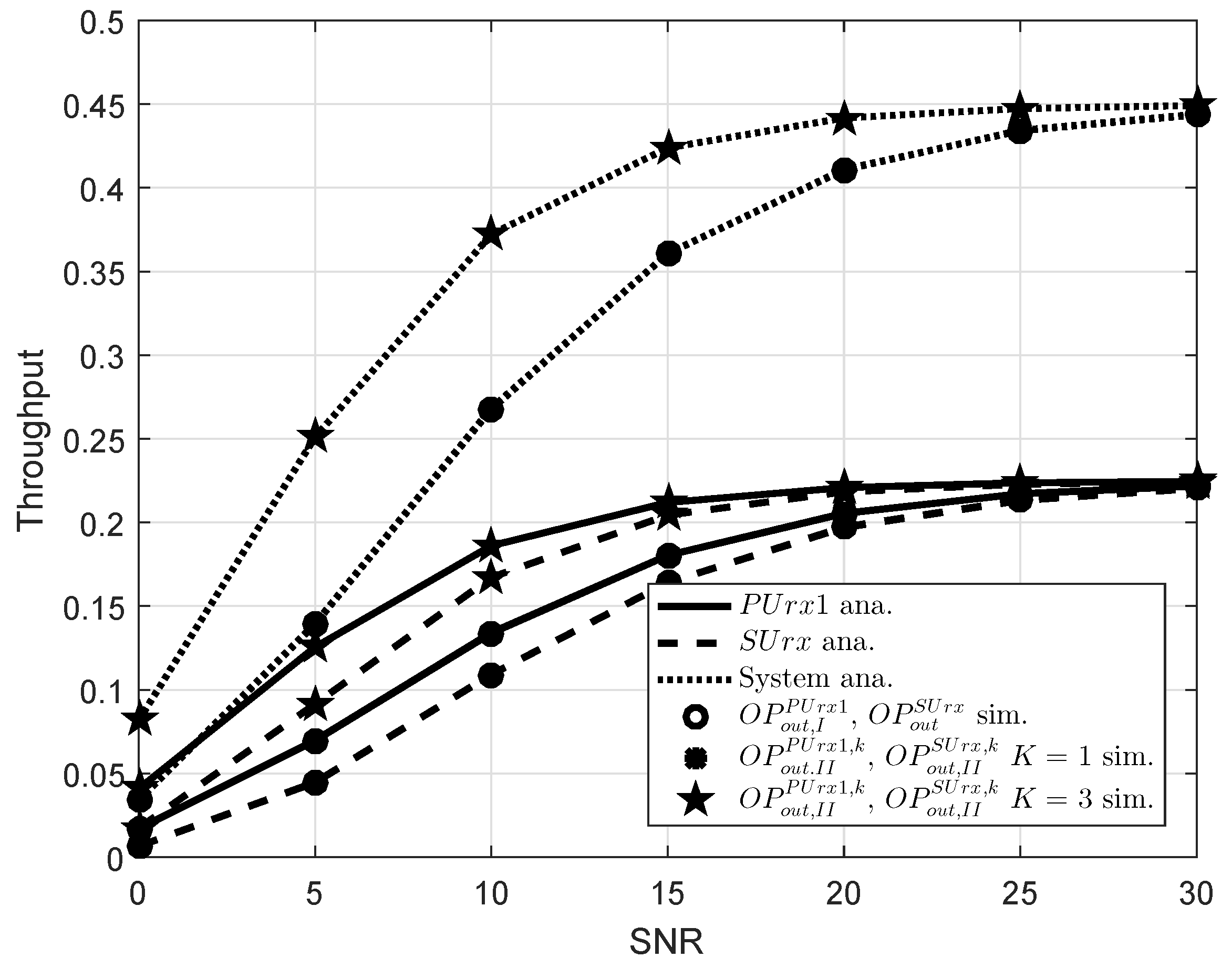
  • The exact expressions of outage probability is presented and then throughput is further examined. From the achieved results, we analyze the effects of a number of factors including power allocation factors, transmit SNR, and the number of relays to prove the superiority of such CR NOMA model.
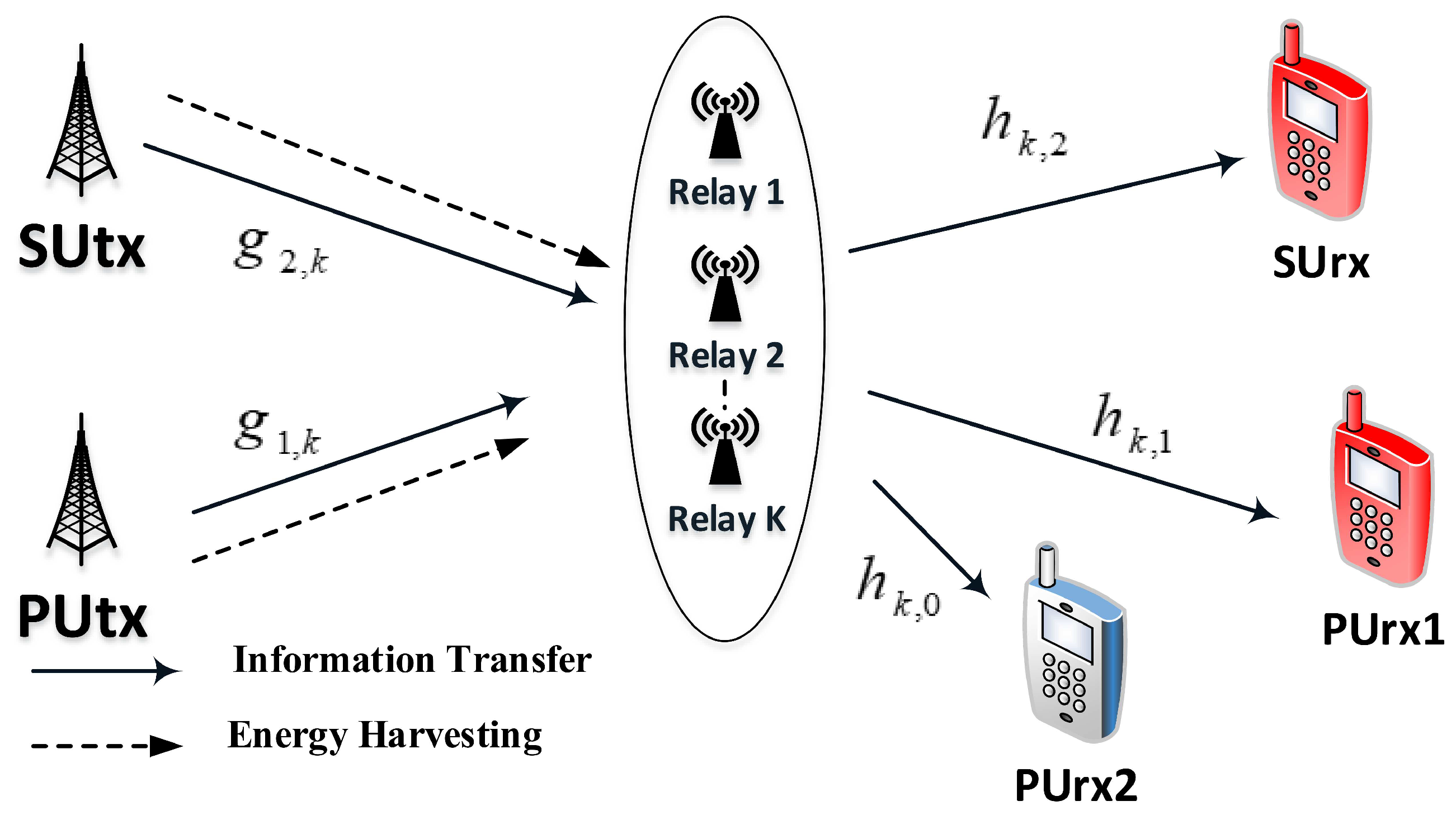
  • As extended model, multiple relay selection in Scheme 2 is introduced in EH assisted CR NOMA to increase data rate and reliability of transmission compared to singe relay systems reported in Scheme 1. Moreover, the EH assisted CR-NOMA systems illustrate an improved performance as increasing the number of selected relays.
The remaining sections are organized as follows. Section 2 describes the system model of EH assisted CR-NOMA. Section 3 analyzes the outage probability and throughput performance with fixed power allocation factors assigned for NOMA users in Scheme 1 and Section 4 presents Scheme 2. Next, numerical results are provided in Section 5. The conclusion is presented in Section 6.

2. System Model

To begin with describing the structure of considered system, we design the EH assisted CR-NOMA network to simultaneous supply energy and information transmission. At transmit side, the primary network is designed with one primary user (PUtx) and a secondary network containing one secondary transmitter (SUtx) while PUrx1, PUrx2, and SUrx are considered as destinations at the receiver side (in which only PUrx2 is located near the relay). This paper intends to evaluate performance of distant users (PUrx1 and SUrx) as in Figure 1. We consider the case that PUtx and SUtx want to send information to relay (R) in the uplink NOMA and then R transfers the signal to the main PUrx1 user and the secondary user SUrx in the downlink NOMA. We assume PUrx1 is not within the transmission line of PUtx and needs a relay node to support the communication process. Assume a secondary user R plays the role of intermediate node, which is able to harvest energy to support further transmission. It can be seen that the first hop in such network is operated in the model of energy harvesting. In particular, both secondary nodes R are capable of scavenging the energy from received signals (RF bearing signal). Moreover, all nodes are the half-duplex mode and are equipped with only one antenna.
There are two phases in the operation of CR NOMA. The PUtx and SUtx transfer their information to R in Phase 1. Then, the relay node R takes advantage of the harvested power from the part of received signals from the sources to forward the obtained signals to SUrx and PUrx1 in Phase 2.
It is assumed that the main user PUtx has a fixed power supply, i.e., P S , while there is dynamic energy supply for the relay node R and hence R needs to collect power from the received signals in Phase 1. All channels experience the quasi-static Rayleigh fading channels. Let g 1 and g 2 be the channel coefficients at first hop, while h i , i = 1 , 2 are channels in second hop to SUrx and PUrx1, and h 0 is channel to PUrx2. Then, we denote channel gains as g i C N 0 , Ω g i and h i C N 0 , Ω i for i = 1 , 2 , 3 .
Figure 1 shows that the energy harvesting and information transfer protocol comprises two phases. In Phase 1, the PUtx transfers the superposition signal to relay, where x 1 and x 2 are the information that BS plans to transfer to PUrx1 and SUrx, respectively. a i , ( i = 1 , 2 ) is the power allocation coefficient for two far NOMA users. It is assumed that a 1 2 + a 2 2 = 1 and a 1 2 > a 2 2 > 0 . We also indicate the additive white Gaussian noise (AWGN) at all users in the network are ω R C N ( 0 , σ R 2 ) in this paper.
In the second scenario in Figure 2, it is assumed that the k-th ( k = 1 , 2 , , K ) relay is selected to signal forwarding to destinations including SUrx, PUrx1, and PUrx2. Since the secondary network benefits from the sharing of licensed channel of the primary network, the user SUrx is able to receive its own signal. While the selected relay is willing to help the primary users to enhance their performance to serve both PUrx1 and PUrx2. This scheme further provides a chance to improve performance of far users by exploiting relay selection scheme. It is noted that, regarding these schemes, Schemes 1 and 2 are presented to exhibit performance gap among far users illustrated in Figure 1 and Figure 2, respectively.
We denote g 1 , k , g 2 , k as channels of links PUtx to kth relay, and SUtx to kth relay, respectively, while channels from kth relay to PUrx2, PUrx1 and SUrx are h k , 0 , h k , 1 , h k , 2 , respectively.

3. Performance Analysis in Scheme 1

3.1. Calculation of SNR

It is assumed that equal level of transmit power P S is allocated for sources in primary and secondary network. With regard to evaluating system performance for Scheme 1 in Phase 1, the main PUtx transfers its information to relay node R following NOMA structure, and the received signal at R is given by
y R 1 = P S g 1 a 1 x 1 + a 2 x 2 + ω R .
The primary SUtx transmits its information to the relay node R following OMA scheme and such received signal in secondary link is given by
y R 2 = P S g 2 x 3 + ω R .
The signal transmission in the system is separated into two phases. The first phase is deployed for transmission both information and energy from source to relay and relay forwards the received signal to destinations in the second phase.
Employing the method of power splitting based EH protocol [7,8,9,10,11], the received information can be separated into two parts by R, one for energy harvesting and another for information processing. The received signal with respect to EH at relay for primary link is given by
λ 1 y R 1 = P s λ 1 g 1 a 1 x 1 + a 2 x 2 + λ 1 ω R .
Here, 0 < λ 1 < 1 is the part of information splitting for EH of R for two considered links. It is important that R takes advantage of all the collected power to forward the received signal to PUrx1 and SUrx yielding λ 1 = 0 or λ 1 = 1 . Therefore, the transmitted power of the relay node for primary link and secondary link can be calculated, respectively, as
P R 1 = η λ 1 P S g 1 2
and
P R 2 = η λ 1 P S g 2 2 .
Here, 0 η 1 indicates the energy conversion efficiency. In Phase 2, the relay node R then forwards 1 λ 1 y R together with the secondary information x 2 based on the AF scheme and the superposition coding. The relay node harvests total power of P R = P R 1 + P R 2 and then R can split its power into two parts: P R = λ 3 P R + 1 λ 3 P R . More specifically, λ 3 P R is used to forward the main information transmitted from PUtx to the primary destination PUrx1 and PUrx2, while 1 λ 3 P R is used to transfer the secondary information to the secondary destination SUrx.
The power amplify factor G i of relay is given by
G i = 1 1 λ 1 P S g i 2 + σ R 2 + σ b 1 2 1 1 λ 1 P S g i 2 ,
where the approximation is tight at high SNR.
The received signal at the relay node R for primary link and secondary link are given by
x R 1 = G 1 λ 3 P R 1 λ 1 y R 1 + ω b 1
and
x R 2 = G 2 1 λ 3 P R 1 λ 1 y R 2 + ω b 1 ,
where all signals are considered as the unit-power transmitted information. ω b 1 C N 0 , σ b 1 2 denotes the white Gaussian noise demonstrated by the signal conversion from passband to baseband at R.
In this step, the received signal at user PUrx1 and SUrx can be expressed, respectively, as
y P U r x 1 = h 1 x R 1 + n 3 = 1 λ 1 λ 3 P R P S G 1 g 1 h 1 a 1 x 1 + 1 λ 1 λ 3 P R P S G 1 g 1 h 1 a 2 x 2 + 1 λ 1 λ 3 P R G 1 h 1 n R + λ 3 P R h 1 G 1 n b 1 + n 3 ,
y S U r x = h 2 x R 2 + n 3 = 1 λ 1 1 λ 3 P R P S G 2 g 2 h 2 a 1 x 3 + 1 λ 1 1 λ 3 P R G 2 h 2 n R + 1 λ 3 P R h 2 G 2 n b 1 + n 3 ,
where n 3 C N ( 0 , σ 3 2 ) denotes the additive noise at PUrx1 and SUrx. The primary user PUrx1 tries to recover from y P U r x 1 in the existence of the interference from the PUrx2. The signal-to-interference-plus-noise ratio (SINR) of PUrx1 to detect x 1 is thus given by
γ x 1 = η λ 1 λ 3 P S g 1 2 h 1 2 a 1 2 η λ 1 λ 3 h 1 2 P S g 1 2 a 2 2 + σ R 2 + η λ 1 λ 3 1 λ 1 h 1 2 σ b 1 2 + σ 3 2 .
After performing successive interference cancellation (SIC) applied in the NOMA, system decodes the signal x 2 of user PUrx2. Regarding OMA, x 2 is decoded at the SUrx via expected SINR as
γ x 3 = η λ 1 λ 3 P S g 2 2 h 2 2 η λ 1 λ 3 h 2 2 σ b 1 2 + η λ 1 λ 3 1 λ 1 h 2 2 σ b 1 2 + σ 3 2 .
Consequently, the data rates gained at the primary user PUrx1 and the secondary user SUrx can be expressed, respectively, by
τ P U r x 1 = 1 2 log 2 1 + γ x 1 ,
and
τ S U r x = 1 2 log 2 1 + γ x 3 .

3.2. Outage and Throughput Performance Analysis

This section provides an analysis of the outage probability and throughput in delay-limited mode for PUrx1 and SUrx. In addition, an investigation is conducted about harvested energy for power transfer at the secondary user.
There is an outage event if the data rates of PUrx1 and SUrx are lower than the given target rates. Thus, the outage probability for a given target rate R j , j = P U r x 1 , S U r x are computed by
O P o u t j ( τ j < R j ) = O P o u t j ( γ j < ε j ) .
Here, we use ε j = 2 2 R j 1 . To further proceed system performance analysis, we have the following propositions.
Proposition 1.
The outage probability for the primary user PUrx1 in the cognitive relay network is then expressed by
  • If ε P U r x 1 l D m D
    O P o u t P U r x 1 = 1 .
  • If ε P U r x 1 < l D m D
    O P o u t P U r x 1 = Pr γ x 1 < ε D = 1 exp ε P U r x 1 k D Ω g 1 l D m D ε P U r x 1 4 ε P U r x 1 Ω 1 Ω g 1 l D m D ε D K 1 4 ε P U r x 1 Ω 1 Ω g 1 l D m D ε P U r x 1 ,
where l D = η λ 1 λ 3 P S a 1 2 σ 2 , m D = η λ 1 λ 3 P S a 2 2 σ 2 , k D = η λ 1 λ 3 1 + 1 1 λ 1 . K 1 . is the modified Bessel function of the second kind with first order defined in [27].
Proof. 
See Appendix A. □
Proposition 2.
The outage probability of the secondary user SUrx in OMA mode can be expressed as
  • If g 2 2 < ε S U r x 1 k C l C
    O P o u t S U r x = 1 .
  • If g 2 2 > ε S U r x 1 k C l C
    O P o u t S U r x = Pr γ x 3 < ε S U r x 1 = 1 exp ε S U r x 1 k C l C Ω g 2 4 ε S U r x 1 Ω g 2 Ω 2 l C K 1 4 ε S U r x 1 Ω g 2 Ω 2 l C ,
where l c = η λ 1 λ 3 P S σ 2 , k c = η λ 1 1 λ 3 1 + 1 1 λ 1 .
Proof. 
Similar derivations can be found in Appendix A. Therefore, it can be omitted it here. □

3.3. Consideration on Overall Performance in Terms of Outage Behavior and Throughput

In this paper, we only examine performance of far users who are under poor channel condition, then the overall outage probability can be formulated by
O P o u t , I = 1 1 O P o u t , I P U r x 1 1 O P o u t , I S U r x .
Therefore, it can be obtained partial throughput at PUrx1 and SUrx for scheme I as
ψ j , I = 1 O P o u t , I j R j 1 λ 3 T / 2 T = 1 O P o u t , I j R j 1 λ 3 2 , j = P U r x 1 , S U r x .
In this case, the overall throughput performance can be further written by
ψ s y s t e m , I = ψ P U r x 1 , I + ψ S U r x , I .

4. Performance Analysis in Scheme 2

In Phase 1, the main PUtx transfers its information to the relay node. The received signal can be calculated in secondary link as
y R 1 , k = P S g 1 , k a 1 x 1 + a 2 x 2 + ω R ,
and the primary SUtx transmits its information to the relay node and received signal at relay for secondary link is given by
y R 2 , k = P S g 2 , k a 1 x 3 + a 2 x 4 + ω R .
It is thus assumed that σ 2 = σ b 1 2 = σ b 1 2 = σ 3 2 . The SINR of PUrx1 to detect x 1 is then formulated by
γ x 1 , k = η λ 1 λ 3 P S g 1 , k 2 h k , 1 2 a 1 2 η λ 1 λ 3 h k , 1 2 P S g 1 , k 2 a 2 2 + σ 2 + η λ 1 λ 3 1 λ 1 h k , 1 2 σ 2 + σ 2 .
Similarly, the SINR need be calculated to decode the signal x 3 of user SUrx as
γ x 3 , k = η λ 1 λ 3 P S g 2 , k 2 h k , 2 2 η λ 1 λ 3 h k , 2 2 σ 2 + η λ 1 λ 3 1 λ 1 h k , 2 2 σ 2 + σ 2 .
The selected relay index and its respective SNR are given as [28]
k = a r g max k = 1 , , K γ i i , k , i i = x 1 , x 3 .
Proposition 3.
The outage probability for the primary user PUrx1 in the EH-enabled CR-NOMA is then expressed by
  • If ε P U r x 1 l D m D
    O P o u t , I I P U r x 1 = 1 .
  • If ε P U r x 1 < l D m D
    O P o u t , I I P U r x 1 , k = 1 k = 1 K K k 1 k 1 exp k ε P U r x 1 k D Ω g 1 , k l D ε P U r x 1 m D × 4 k ε P U r x 1 Ω k , 1 Ω g 1 , k l D ε P U r x 1 m D K 1 4 k ε P U r x 1 Ω k , 1 Ω g 1 , k l D ε P U r x 1 m D .
Proof. 
See in Appendix B. □
Proposition 4.
The outage probability of the secondary user SUrx in NOMA mode can be expressed in two cases as
  • If g 2 , k 2 < ε S U r x k C l C
    O P o u t , I I S U r x , k = 1 .
  • If g 2 , k 2 > ε S U r x k C l C
    O P o u t , I I S U r x , k = Pr γ x 3 , k < ε S U r x = 1 k = 1 K K i 1 k 1 exp k ε S U r x k C l C Ω g 2 , k 4 k ε S U r x Ω g 2 , k Ω 2 , k l C K 1 4 k ε S U r x Ω g 2 , k Ω 2 , k l C .
Proof. 
It can be recalled such outage event as
O P o u t , I I S U r x , k = Pr γ x 3 , k < ε S U r x = 1 Pr η λ 1 λ 3 P S a 2 2 σ 2 g 2 , k 2 h k , 2 2 η λ 1 λ 3 1 + 1 1 λ 1 h k , 2 2 + 1 ε S U r x = 1 Pr g 2 , k 2 ε S U r x k C h k , 2 2 + ε S U r x l C h k , 2 2 .
Using characterizations of probability of random variables, it can be rewritten as
O P o u t , I I S U r x , k = 1 0 k = 1 K K k 1 k 1 exp ε S U r x k k C x + k ε S U r x l C Ω g 2 , k x 1 Ω k , 2 exp x Ω k , 2 d x = 1 1 Ω k , 2 k = 1 K K k 1 k 1 exp ε S U r x k k C l C Ω g 2 , k 0 exp k ε S U r x l C Ω g 2 , k x x Ω k , 2 d x = 1 k = 1 K K k 1 k 1 exp ε S U r x k k C l C Ω g 2 , k 4 k ε S U r x l C Ω g 2 , k Ω k , 2 K 1 4 k ε S U r x l C Ω g 2 , k Ω k , 2 .
The proof is completed. □
The overall outage performance in Scheme 2 can be given as
O P o u t , I I k = 1 1 O P o u t , I I P U r x 1 , k 1 O P o u t , I I S U r x , k .
From Propositions 3 and 4, the outage probability at both PUrx1 and SUrx can be achieved. We concentrate on throughput for both primary network and secondary in this paper, i.e., ψ j k . 1 λ 3 T 1 λ 3 T 2 2 is time constant and where T (second) is time epoch to transmit signal from source to destination. Therefore, it can be obtained partial throughput at PUrx1 and SUrx as
ψ j , I I k = 1 O P o u t , I I j , k R j 1 λ 3 T / 2 T = 1 O P o u t , I I j , k R j 1 λ 3 2 , j = P U r x 1 , S U r x .
In this regard, the overall throughput is computed by
ψ s y s t e m , I I k = ψ P U r x 1 , I I k + ψ S U r x , I I k .

5. Simulation Results

Numerical results were examined to compare the performance of primary/secondary network obtained by using these considered schemes. The outage behavior of the proposed EH assisted CR NOMA was also evaluated in the simulations. The simulation settings were based on similar parameters as in [13,14]; the common parameters related to average channel gains were Ω g 1 = Ω g 2 = Ω 1 = Ω 2 = 1 , λ 1 = λ 3 = 0.1 , and power efficiency was η = 1 . All channels are assumed to be Rayleigh flat fading. In following figures, we denote “ana.” to illustrate for simulations corresponding to mathematical results, “System ana.” indicates overall system performance, and “sim.” stands for Monte-Carlo simulation.
In Figure 3, we illustrate outage probability of primary and secondary networks. We set d 1 = 1 / 2 as distance from PUtx/SUtx to relay, d 2 = 1 d 1 as distance from relay to PUrx1, d 3 = 1 / 4 as distance from relay to SUrx, and λ 1 = λ 3 = 0.1 . It can be seen clearly that higher SNR leads to enhanced outage performance. Furthermore, higher acquired requirement on target rates results in the worse outage performance of both main users. This phenomenon can be explained as follows: target rates limit outage performance, as confirmed by Equation (15). Figure 3 indicated that higher data rates threshold is main reason to decreasing outage performance. Changing power allocation factors results in outage performance gap, as shown in Figure 4. This situation can be clarified as follows: higher value a 1 contributes to worse SINR and hence degraded outage performance occurred.
In Figure 5, we highlight different trend of PUrx1 and SUrx as varying a 1 2 . In this simulation, we set d 1 = 1 / 2 as distance from PUtx to relay, d 2 = 1 d 1 as distance from relay to PUrx1, d 3 = 1 / 4 as distance from relay to SUrx, λ 1 = λ 3 = 0.1 , and R P U r x 1 = R S U r x = 0.5 . It can be observed clearly that different trends in term of outage behavior for PUrx1 and SUrx can be raised. The lower outage performance can be seen at PUrx1 as increasing a 1 2 from 0.2 to 0.9 and the opposite trend can be raised for SUrx. The main reason is that a 1 2 is contained in the expressions of SINR and such value make direct impact of SINR and then outage performance will be changed. Interestingly, overall outage system is certainly at middle point of considered range of a 1 2 . This situation can be explained by a 1 2 must be satisfied fairness between SU and PU.
Figure 6 shows similar trend of outage performance in three values of target rate R P U r x 1 = R S U r x = 0.1 , 0.5 , 0.9 . In this case, we set R P U r x 1 = R S U r x ( a 1 = 0.85 , η = 1 , K = 2 ). It is worth noting that outage performance of P U r x 1 , k is worst case as R P U r x 1 = R S U r x = 0.9 and it leads to worse overall performance as well. Figure 7 illustrates impact of power allocation factors on outage performance. The similar performance of Scheme 2 can be achieved in such figure. In this case, we set d 3 = 1 / 4 as the distance from relay to SUrx, and R P U r x 1 = R S U r x = 0.3, K = 2 .
Figure 8 also indicates similar performance of Scheme 2 under varying power allocation factor a 1 . Especially, more relays contribute to improve outage performance of Scheme 2, as shown in Figure 9, i.e., K = 3 is the better one. The simulation parameters in Figure 9 are a 1 = 0.85, R P U r x 1 = R S U r x = 0.1.
It can be confirmed that Scheme 2 exhibits the best performance corresponding to K = 3 considering outage performance and throughput, as shown in Figure 10 and Figure 11. In these case, we set a 1 = 0.85, R P U r x 1 = R S U r x = 0.1. Regarding the comparison scenario shown in Figure 10, the related parameters of model in [14] were aligned as a 1 = 0.85 , R = 0.1, Ω 1 = Ω 2 = 1, α = β = 0.1, η = 1 , d = d 1 = 2, and m = 3 . It can be observed that outage performance in the proposed two schemes is better than exact outage reported in [14].

6. Conclusions

This study investigated a new spectrum efficiency as deploy EH in such CR-NOMA. In this model, both the primary and the secondary receivers who are located far way benefit from EH based relay. Such wireless powered relay intends to serve both primary and secondary networks. To examine the performance of EH-enabled CR-NOMA, expressions for the outage probability and throughput for each user and the entire NOMA network were analyzed. In addition, we demonstrated that the effect of transmit SNR, power allocation factors, and target rates are main factors affecting on performance of EH assisted CR-NOMA. In future work, multiple users of the such CR-NOMA model should be studied.

Author Contributions

D.-T.D. designed the algorithm, performed the theoretical analysis, checked the results and wrote the manuscript. M.-S.V.N. implemented the simulation and contributed to the manuscript preparation. M.V. was responsible for formulating the research issues, and revised the paper.

Funding

This research was funded by the Ministry of Education, Youth and Sport of the Czech Republic under SGS grant No. SP2019/41 conducted at VSB, Technical University of Ostrava.

Conflicts of Interest

The authors declare no conflict of interest.

Appendix A. Proof of Proposition 1

Based on Equation (10), the outage probability for the primary user PUrx1 in the EH-enabled CR-NOMA can be obtained as follows
O P o u t , I P U r x 1 = Pr γ x 1 < ε P U r x 1 = 1 Pr l D g 1 2 h 1 2 m D g 1 2 h 1 2 + k D h 1 2 + 1 ε P U r x 1 = 1 Pr g 1 2 ε P U r x 1 k D h 1 2 + 1 l D ε P U r x 1 m D h 1 2 .
Such outage event must be constrained by ε P U r x 1 < l D m D , and then O P o u t , I P U r x 1 can be expressed by
O P o u t , I P U r x 1 = 1 0 exp ε P U r x 1 k D x + 1 l D ε P U r x 1 m D x Ω g 1 1 Ω 1 exp x Ω 1 d x = 1 1 Ω 1 exp ε P U r x 1 k D Ω g 1 l D ε P U r x 1 m D 0 exp ε P U r x 1 Ω g 1 l D ε P U r x 1 m D x x Ω 1 d x
To calculate the above integral, we put new variable as t = Ω g 1 l D ε P U r x 1 m D x x = t Ω g 1 l D ε P U r x 1 m D , and then it can be expressed by
O P o u t , I P U r x 1 = 1 1 Ω 1 Ω g 1 l D ε P U r x 1 m D exp ε P U r x 1 k D Ω g 1 l D ε P U r x 1 m D × 0 exp ε P U r x 1 t t Ω 1 Ω g 1 l D ε P U r x 1 m D d t
Note that Equation (A3) can be calculated by applying 0 exp β 4 x γ x d x = β γ K 1 β γ in ([27], Equation (3.324)), and then we have Equation (16).
This completes the proof.

Appendix B. Proof of Proposition 3

By definition, we have such outage probability as
O P o u t , I I P U r x 1 , k = Pr γ x 1 , k < ε D = 1 Pr l D g 1 , k 2 h k , 1 2 m D g 1 , k 2 h k , 1 2 + k D h k , 1 2 + 1 ε D = 1 Pr g 1 , k 2 ε D k D h k , 1 2 + 1 l D ε D m D h k , 1 2
In this case, the cumulative distribution function (CDF) related to selected channel are given respectively by [28]
F g i , k 2 x = 1 k = 1 K K k 1 k 1 exp k x λ g .
By using partial integration and the CDF of g i , k 2 , O P o u t , I I P U r x 1 , k is formulated as
O P o u t , I I P U r x 1 , k = 1 0 1 F g 1 , k 2 ε D k D x + 1 l D ε D m D x f h k , 1 2 x d x = 1 0 k = 1 K K i 1 k 1 exp k ε D k D x + 1 l D ε D m D Ω g 1 , k x 1 Ω k , 1 exp x Ω k , 1 d x
It can be rewritten as
O P o u t , I I P U r x 1 , k = 1 1 Ω k , 1 k = 1 K K i 1 k 1 exp k ε P U r x 1 k D Ω g 1 , k l D ε P U r x 1 m D × 0 exp k ε P U r x 1 Ω g 1 , k l D ε P U r x 1 m D x x Ω k , 1 d x .
Let us change new variables as t = Ω g 1 , k l D ε P U r x 1 m D x x = t Ω g 1 , k l D ε P U r x 1 m D
Hence, O P o u t , I I P U r x 1 , k can be formulated as below
O P o u t , I I P U r x 1 , k = 1 1 Ω k , 1 Ω g 1 , k l D ε P U r x 1 m D k = 1 K K k 1 k 1 exp k ε P U r x 1 k D Ω g 1 , k l D ε P U r x 1 m D 0 exp k ε P U r x 1 t t Ω k , 1 Ω g 1 , k l D ε P U r x 1 m D d t = 1 k = 1 K K k 1 k 1 exp k ε P U r x 1 k D Ω g 1 , k l D ε P U r x 1 m D × 4 k ε P U r x 1 Ω k , 1 Ω g 1 , k l D ε P U r x 1 m D K 1 4 k ε P U r x 1 Ω k , 1 Ω g 1 , k l D ε P U r x 1 m D .
This completes the proof.

References

  1. Lv, L.; Chen, J.; Ni, Q. Cooperative Non-Orthogonal Multiple Access in Cognitive Radio. IEEE Commun. Lett. 2016, 20, 2059–2062. [Google Scholar] [CrossRef] [Green Version]
  2. Wei, L.; Jing, T.; Fan, X.; Wen, Y.; Huo, Y. The Secrecy Analysis over Physical Layer in NOMA-Enabled Cognitive Radio Networks. In Proceedings of the 2018 IEEE International Conference on Communications (ICC), Kansas City, MO, USA, 20–24 May 2018; p. 16. [Google Scholar]
  3. Wang, D.; Men, S. Secure Energy Efficiency for NOMA Based Cognitive Radio Networks with Nonlinear Energy Harvesting. IEEE Access 2018, 6, 62707–62716. [Google Scholar] [CrossRef]
  4. Do, D.-T.; Nguyen, H.-S.; Voznak, M.; Nguyen, T.-S. Wireless powered relaying networks under imperfect channel state information: system performance and optimal policy for instantaneous rate. Radioengineering 2017, 26, 869–877. [Google Scholar] [CrossRef]
  5. Bae, Y.H.; Baek, J.W. Optimal Design of RF Energy-Harvesting Network: Throughput and Delay Perspective. Sensors 2019, 19, 145. [Google Scholar] [CrossRef] [PubMed]
  6. Gunduz, D.; Devillers, B. Two-hop communication with energy harvesting. In Proceedings of the 2011 4th IEEE International Workshop on Computational Advances in Multi-Sensor Adaptive Processing (CAMSAP), San Juan, Puerto Rico, 13–16 December 2011; pp. 201–204. [Google Scholar]
  7. Xin, J.; Liu, W.; Zhang, C.; Liu, A. An Energy Conserving and Transmission Radius Adaptive Scheme to Optimize Performance of Energy Harvesting Sensor Networks. Sensors 2018, 18, 2885. [Google Scholar] [Green Version]
  8. Liu, X.; Jia, Y.; Wen, Z.; Zou, J.; Li, S. Beamforming Design for Full-Duplex SWIPT with Co-Channel Interference in Wireless Sensor Systems. Sensors 2018, 18, 3362. [Google Scholar] [CrossRef] [PubMed]
  9. Nguyen, T.N.; Do, D.-T.; Tran, P.T.; Voznak, M. Time Switching for Wireless Communications with Full-Duplex Relaying in Imperfect CSI Condition. KSII Trans. Internet Inf. Syst. 2016, 10, 4223–4239. [Google Scholar]
  10. Nguyen, T.-L.; Do, D.-T. Exploiting Impacts of Intercell Interference on SWIPT-assisted Non-orthogonal Multiple Access. Wirel. Commun. Mob. Comput. 2018, 2018, 2525492. [Google Scholar] [CrossRef]
  11. Nguyen, K.T.; Do, D.-T.; Nguyen, X.X.; Nguyen, N.T.; Ha, D.H. Wireless information and power transfer for full duplex relaying networks: performance analysis. In Proceedings of the Recent Advances in Electrical Engineering and Related Sciences (AETA 2015), Ho Chi Minh City, Vietnam, 9–12 December 2015; pp. 53–62. [Google Scholar]
  12. Tran, T.-N.; Do, D.-T.; Voznak, M. On Outage Probability and Throughput Performance of Cognitive Radio Inspired NOMA Relay System. Adv. Electr. Electron. Eng. 2018, 16, 501–512. [Google Scholar] [CrossRef]
  13. Men, J.; Ge, J.; Zhang, C. Performance analysis of non-orthogonal multiple access for relaying networks over nakagami-m fading channels. IEEE Trans. Veh. Technol. 2017, 66, 1200–1208. [Google Scholar] [CrossRef]
  14. Do, D.T.; Le, C.-B. Application of NOMA in Wireless System with Wireless Power Transfer Scheme: Outage and Ergodic Capacity Performance Analysis. Sensors 2018, 18, 3501. [Google Scholar] [CrossRef] [PubMed]
  15. Zhang, N.; Wang, J.; Kang, G.; Liu, Y. Uplink nonorthogonal multiple access in 5G systems. IEEE Commun. Lett. 2016, 20, 458–461. [Google Scholar] [CrossRef]
  16. Ding, Z.; Fan, P.; Poor, H.V. Impact of User Pairing on 5G Nonorthogonal Multiple Access Downlink Transmissions. IEEE Trans. Vehic. Tech. 2016, 65, 1462–1465. [Google Scholar] [CrossRef]
  17. Ding, Z.; Schober, R.; Poor, H.V. A General MIMO Framework for NOMA Downlink and Uplink Transmission Based on Signal Alignment. IEEE Trans. Wirel. Commun. 2016, 15, 4438–4454. [Google Scholar] [CrossRef]
  18. Liu, Y.; Ding, Z.; Elkashlan, M. Non-orthogonal Multiple Access in Large-Scale Underlay Cognitive Radio Networks. IEEE Trans. Vehic. Tech. 2016, 65, 152–157. [Google Scholar] [CrossRef]
  19. Lv, L.; Ni, Q.; Ding, Z. Application of Non-Orthogonal Multiple Access in Cooperative Spectrum-Sharing Networks over Nakagami-m Fading Channels. IEEE Trans. Vehic. Tech. 2017, 66, 5506–5511. [Google Scholar] [CrossRef]
  20. Lv, L.; Ni, Q.; Ding, Z. Design of Cooperative Non-Orthogonal Multicast Cognitive Multiple Access for 5G Systems: User Scheduling and Performance Analysis. IEEE Trans. Commun. 2017, 65, 2641–2656. [Google Scholar] [CrossRef] [Green Version]
  21. Kader, F.; Shin, S.Y. Cooperative Spectrum Sharing with Space Time Block Coding and Non-Orthogonal Multiple Access. In Proceedings of the 8th ICUFN, Vienna, Austria, 5–8 July 2016. [Google Scholar]
  22. Zhang, Y.; Yang, Q.; Zheng, T. Energy Efficiency Optimization in Cognitive Radio Inspired Non-Orthogonal Multiple Access. In Proceedings of the IEEE 27th PIMRC, Valencia, Spain, 4–8 September 2016. [Google Scholar]
  23. Liu, X.; Wang, Y.; Liu, S.; Meng, J. Spectrum Resource Optimization for NOMA-Based Cognitive Radio in 5G Communications. IEEE Access 2018, 6, 24904–24911. [Google Scholar] [CrossRef]
  24. Nandan, N.; Majhi, S.; Wu, H.-C. Secure Beamforming for MIMO-NOMA Based Cognitive Radio Network. IEEE Commun. Lett. 2018. [Google Scholar] [CrossRef]
  25. Wang, Q.; Ge, J.; Li, Q.; Bu, Q. Joint Relay and Antenna Selection for Cognitive Radio-Inspired Non-orthogonal Multiple Access. In Proceedings of the IEEE International Conference on Communications Workshops (ICC), Kansas City, MO, USA, 20–24 May 2018; pp. 1–6. [Google Scholar]
  26. Im, G.; Lee, J.H. Outage Probability for Cooperative NOMA Systems with Imperfect SIC in Cognitive Radio Networks. IEEE Commun. Lett. 2019, 23, 692–695. [Google Scholar] [CrossRef]
  27. Gradshteyn, I.S.; Ryzhik, I.M. Table of Integrals, Series and Products, 6th ed.; Academic Press: New York, NY, USA, 2000. [Google Scholar]
  28. Lee, S.; da Costa, D.B.; Vien, Q.; Duong, T.Q.; de Sousa, R.T. Non-orthogonal multiple access schemes with partial relay selection. IET Commun. 2017, 11, 846–854. [Google Scholar] [CrossRef]
Figure 1. Scheme 1: System model of EH assisted CR-NOMA network.
Energies 12 02206 g001
Figure 2. Scheme 2: Multiple relays in EH assisted CR-NOMA network.
Energies 12 02206 g002
Figure 3. Scheme 1: Outage performance of PUrx1 and SUrx versus transmit SNR at source when R P U r x 1 = R S U r x ( a 1 = 0.85, η = 1 ).
Energies 12 02206 g003
Figure 4. Scheme 1: PUrx1 and SUrx and overall outage of system comparison with respect to varying both SNR and a 1 ( R P U r x 1 = R S U r x = 0.3 ).
Energies 12 02206 g004
Figure 5. Scheme 1: Outage performance of PUrx1 and SUrx under changing of a 1 2 and SNR ( R P U r x 1 = R S U r x = 0.1 ).
Energies 12 02206 g005
Figure 6. Scheme 2: Outage comparison of PUrx1 and SUrx versus SNR.
Energies 12 02206 g006
Figure 7. Scheme 2: Outage performance of PUrx1 and SUrx versus SNR as varying a 1 .
Energies 12 02206 g007
Figure 8. Scheme 2: Performance of PUrx1 and SUrx with a 1 as varying SNR ( R P U r x 1 = R S U r x = 0.1, K = 2 ).
Energies 12 02206 g008
Figure 9. Scheme 2: Impact of K on outage comparison of PUrx1 and SUrx versus SNR.
Energies 12 02206 g009
Figure 10. Comparison of two schemes and work in [14] in terms of outage performance.
Energies 12 02206 g010
Figure 11. Scheme 2: Throughput performance of Schemes 1 and 2 versus SNR ( K = 1 , 3 for Scheme 2).
Energies 12 02206 g011

