Article

Deep Borehole Disposal Safety Case

1
Sandia National Laboratories, Albuquerque, NM 87185, USA
2
Department of Materials Science and Engineering, University of Sheffield, Sheffield S1 3JD, UK
3
Marriott Drilling Group, Chesterfield S45 9BQ, UK
*
Author to whom correspondence should be addressed.
Energies 2019, 12(11), 2141; https://doi.org/10.3390/en12112141
Submission received: 23 April 2019 / Revised: 16 May 2019 / Accepted: 17 May 2019 / Published: 4 June 2019
(This article belongs to the Special Issue Deep Borehole Disposal of Nuclear Waste)

Abstract

:
The safety case for deep borehole disposal of nuclear wastes contains a safety strategy, an assessment basis, and a safety assessment. The safety strategy includes strategies for management, siting and design, and assessment. The assessment basis considers site selection, pre-closure, and post-closure, which includes waste and engineered barriers, the geosphere/natural barriers, and the biosphere and surface environment. The safety assessment entails a pre-closure safety analysis, a post-closure performance assessment, and confidence enhancement analyses. This paper outlines the assessment basis and safety assessment aspects of a deep borehole disposal safety case. The safety case presented here is specific to deep borehole disposal of Cs and Sr capsules, but is generally applicable to other waste forms, such as spent nuclear fuel. The safety assessments for pre-closure and post-closure are briefly summarized from other sources; key issues for confidence enhancement are described in greater detail. These confidence enhancement analyses require building the technical basis for geologically old, reducing, highly saline brines at the depth of waste emplacement, and using reactive-transport codes to predict their movement in post-closure. The development and emplacement of borehole seals above the waste emplacement zone is also important to confidence enhancement.

1. Introduction

This paper develops a preliminary safety case for the deep borehole disposal (DBD) concept. A safety case is an integration of arguments and evidence that describe, quantify, and substantiate the safety of a geologic disposal facility and the associated level of confidence [1,2]. At this early phase of development, the DBD safety case focuses on the generic feasibility of the DBD concept. It is based on potential system designs, waste forms, engineering, and geologic conditions; however, no specific site or regulatory framework exists.
The formal concept of a safety case for the long-term disposal of high-activity waste in an engineered facility located in a deep geologic formation was first introduced by the Nuclear Energy Agency (NEA) [3,4,5] More recently, the U.S. Department of Energy Office of Nuclear Energy has published safety case overviews relevant to geologic disposal in the U.S. [6] and specific to the DBD concept [2,7,8,9].
A central part of the safety case is the safety assessment. There are some differences in the use of the term safety assessment across national programs and over time; the definition used in Freeze et al. [8] and in this report is:
Safety Assessment—An iterative set of assessments for evaluating the performance of a repository system and its potential impact that aims to provide reasonable assurance that the repository system will achieve sufficient safety and meet the relevant requirements for the protection of humans and the environment over a prolonged period. The role of a safety assessment, in a safety case, is (i) to quantify the repository system performance for all selected situations and (ii) to evaluate the level of confidence (i.e., taking into account of the identified uncertainties) in the estimated performance of the system [10]. This encompasses all aspects that are relevant for the safety of the development, operation and closure of the disposal facility, including qualitative aspects, non-radiological issues, and organizational and managerial aspects [11].
The scope of this definition has broadened recently to include not just quantitative analyses, but also a broad range of complementary qualitative evidence and arguments that support the reliability of the quantitative analyses [10]. In this report, the quantitative components of a safety assessment are referred to as “pre-closure safety analysis” and “post-closure performance assessment (PA),” the qualitative component is referred to as “confidence enhancement.”
A number of elements contribute to, and must be described in, the safety case. A general set of safety case elements for geologic disposal (including DBD) are shown in Figure 1. The development of these safety case elements and overviews of the key safety elements are provided in Freeze et al. [8].
The safety standards and the implementing regulations governing the management and disposal of radioactive waste in a geologic repository are the fundamental technical requirements that are addressed in a safety case. In the U.S., such standards are promulgated by the U.S. Environmental Protection Agency (EPA) and the U.S. Nuclear Regulatory Commission (NRC). Although the emphasis here is on the safety case for a U.S. example, deep borehole disposal is being examined by other countries as well [8]. A global overview of potential borehole implementation is presented in Chapman [12].
The current regulatory framework for radioactive waste management in the U.S. Code of Federal Regulations (CFR) focuses on mined geologic repositories and was not intended to be applied to the long-term performance of DBD facilities. Existing general U.S. regulations for disposal of high-activity wastes in geologic repositories (10 CFR 60 (NRC)) and 40 CFR 191 (EPA), first promulgated in 1983 and 1985, respectively, remain in effect, and could be applied to disposal of nuclear waste in deep boreholes, as written [13]. However, these existing regulations would likely be superseded, since they were developed more than 30 years ago and are not consistent with the more recent thinking on regulating geologic disposal concepts that embraces a risk-informed, performance-based approach, such as that represented in the site-specific regulations for Yucca Mountain (10 CFR 63 (NRC) and 40 CFR 197 (EPA)), first promulgated in 2001 [7].
Nonetheless, it is likely that regulations for a DBD facility would be strongly informed by the current regulations. Therefore, the preliminary safety case framework for DBD is developed based on assumptions about the potential regulatory environment. These assumptions are based on:
  • Relevant portions of the existing general standards (10 CFR 60 and 40 CFR 191),
  • Anticipated updates consistent with the risk-informed approach in 10 CFR 63 and 40 CFR 197, and
  • Generic standards that incorporate dose or risk metrics recognized internationally to be important to establishing repository safety.
Key considerations of the aforementioned regulations that might provide insight to future DBD regulations are summarized in Freeze et al. [8].

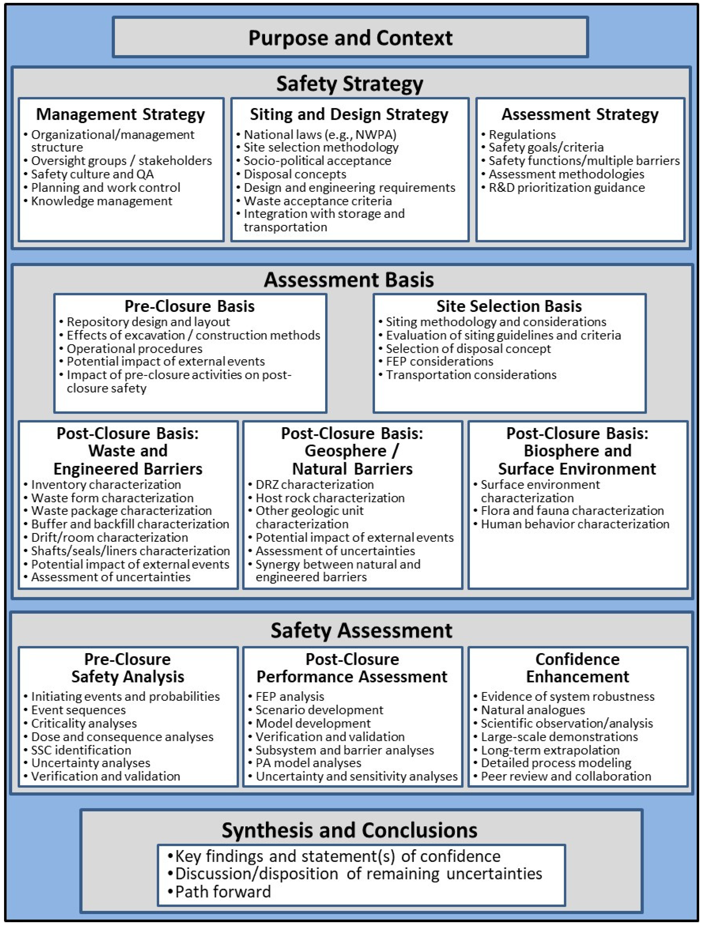
2. Deep Borehole Disposal Assessment Basis

Normally, a safety case, and associated safety assessment and assessment basis, address a specific site, a well-defined inventory, waste form, and waste package, a specific repository design, specific concept of operations, and an established regulatory environment. However, this level of specificity does not currently exist for the DBD concept. Instead, a DBD reference case for disposal of Cs and Sr capsules (hereafter referred to as the “reference case”) in a single borehole in the crystalline basement is established as a surrogate for site-specific and design-specific information upon which a DBD safety case can be developed.
The DBD reference case includes a reference design (disposal concept and surface operations), and information describing the waste, engineered barriers, geosphere and natural barriers, and biosphere. The Cs/Sr capsule DBD reference design includes 108 waste packages in a 534 m waste emplacement zone (EZ) (between 4466m and 5000 m depth), a 2000 m seal zone that directly overlies the top of the EZ (between 2466 m and 4466 m depth), and an upper borehole zone from the top of the seal zone to the surface [8,14].
The pre-closure assessment basis associated with the reference design [15] includes a description of the surface and subsurface facilities (i.e., the borehole) and their operation for use in a quantitative pre-closure safety analysis. Specific pre-closure basis information for the reference case and reference design includes [8,9,16]:
  • DBD site design and layout (surface facilities, borehole, and engineered barriers)
  • Borehole drilling and construction requirements
  • DBD site operations (surface facility operations, waste package surface handling, waste package downhole emplacement, borehole sealing and plugging, and facility closure)
  • Potential impacts of off-normal events (dropping a waste package, retrieval of a waste package stuck in upper portion of borehole, pre-closure breach of a waste package) and/or external/disruptive events (flooding and extreme weather, seismicity, sabotage) on pre-closure safety
  • Potential impacts of pre-closure activities and components on post-closure safety (e.g., waste package stuck in borehole and abandoned, hydrogen (H2) gas generation from metal corrosion, efficacy of borehole seals and plugs)
The post-closure assessment bases associated with the reference design [14] include a description of the natural and engineered barriers for use in the quantitative post-closure PA. Specific post-closure basis information includes [8,9]:
  • Inventory characteristics and quantities (Cs, Sr, and other constituents)
  • Waste form characteristics (degradation and solubility)
  • Waste package characteristics (carbon steel corrosion)
  • Characteristics of the EZ (buffer/backfill/annulus brine evolution, cement plug degradation, perforated steel liner corrosion)
  • Characteristics of the borehole seals (degradation of bentonite seals, cement plugs, and sand/crushed rock ballast)
  • Crystalline basement host rock characteristics (permeability, porosity, diffusion coefficient, thermal properties, pore fluid chemistry, solubility, sorption)
  • DRZ characteristics (extent and properties)
  • Overburden characteristics (sedimentary sequence and properties)
  • Biosphere characteristics (for this preliminary, generic iteration of the safety case, the biosphere is not yet conceptualized and is not part of the PA model)
  • Potential impacts of external events (climate change, glaciation/erosion, seismicity, igneous activity, human intrusion)

3. Deep Borehole Disposal Safety Assessment

In general, a pre-closure operational safety analysis provides a quantitative estimate of the occupational dose from on-site radiation levels and radiological exposures, and the dose to the public from off-site releases of radioactive materials. For this preliminary DBD safety case, a simplified pre-closure safety analysis (PCSA) was performed that calculated the probability of success (which is equal to 1 – probability of failure) of emplacing 108 waste packages (containing all the Cs and Sr capsules) in a single borehole [9,15,16]. Incidents leading to failure included events with minimal effects (e.g., minor worker exposure, low probability of radionuclide release), moderate effects (e.g., moderate worker exposure), and potentially significant effects (e.g., high probability for radionuclide release). For the PCSA base case assumptions, the probability of a successful borehole completion was 95.4%, the probability of a minimal or moderate incident was 4.6%, and the probability of a potentially significant event was only 0.0005% [9]. With achievable minimization of human error probabilities and increased component reliability, the probability of a successful borehole completion rises to 99.4%, and the probability of a potentially significant event drops to 0.0001% [9].
A post-closure PA provides a quantitative estimate of radiological exposures to members of the public, and radiological releases to the accessible environment. For this preliminary DBD safety case, post-closure PAs were performed for (i) an undisturbed (nominal) scenario that included radionuclide transport in the borehole, in the DRZ around the borehole, and in the surrounding rock away from the borehole [8,9,14], and (ii) a disturbed scenario that included a waste package “stuck” in the crystalline basement above the EZ near a hypothetical borehole-intersecting fracture [8,9]. For the undisturbed scenario, PA results suggest that 135Cs (the longest-lived mobile radionuclide in the reference inventory) migrates only a few tens of meters away from the EZ after 10,000,000 years [8,9,14]. For the disturbed (stuck package) scenario, even with a regional head gradient, 135Cs is advected a distance of only about 200 m up the borehole-intersecting fracture over the course of the 10,000,000-year simulation [9]. These post-closure PA model results for both the nominal and disturbed (stuck package) scenarios suggest that there is minimal radionuclide migration away from the EZ and zero dose for 10,000,000 years, at which time long-lived 135Cs has almost completely decayed away.
In a safety case, confidence enhancement refers to information that provides additional support for the quantitative pre-closure and post-closure safety assessments. It includes qualitative or quantitative evidence, arguments, scientific observations, and/or analyses that were not directly included in the pre-closure and post-closure safety assessment models, but that provide additional insights into the robustness, behavior, and evolution of the repository system [8].
Confidence in the DBD concept, supporting the quantitative assessments, derives from:
Pre-Closure Operations [16]:
  • Adequacy of site characterization
  • Achievability of deep drilling
  • Safety of site operations
Post-Closure Isolation [9,14]:
  • Great depth of disposal
  • Isolation and long residence time of deep groundwater
  • Density stratification of brine at depth
  • Low permeability of crystalline host rock
  • High-likelihood of slow diffusion-dominated radionuclide transport
  • Geochemically-reducing conditions at depth
  • Low permeability and high sorption capacity of seal materials
  • Multi-barrier design
Additional confidence enhancement information presented here includes:
  • Evidence for isolation and long residence time of deep groundwater
  • Hydrologic modeling of density stratification of brine at depth
  • Review of borehole sealing materials and technologies
Information supporting each of these confidence enhancement topics is presented in the following sections.

4. Evidence for Isolation and Long Residence Time of Deep Groundwater

The robustness of the DBD concept relies in large part on the subsurface hydrogeology and geochemistry, specifically: Low permeability and porosity in the host rock; lack of significant vertical connectivity in the DRZ; chemically reducing, high salinity, and density-stratified groundwater at depth, and evidence of isolation of deep groundwater. The measurement and confirmation of these heterogeneous properties and conditions pose technical challenges.
A preliminary borehole sampling and testing strategy [17] was developed for key parameters that need to be measured in the 2-to 5-km depth range encompassing the seal zone and the EZ. The testing and sampling strategy has recently been revised [18]. Key sampling and testing activities that can contribute to better characterization of the subsurface hydrogeology and geochemistry include:
  • Sampling and Evaluation While Drilling: Drilling fluid (mud) logging, coring and core analysis, borehole geophysical logging, single-packer hydraulic testing and sampling, and hydraulic fracturing (mini-frac) test.
  • Open Hole Testing and Sampling: Flowing fluid electrical conductivity (FFEC) logging, multi-packer hydraulic testing and sampling, hydraulic fracturing stress measurement tests, and injection/withdrawal (push-pull) tracer tests.
The testing activities are generally focused on determining (a) geomechanical properties associated with borehole stability that are important during pre-closure drilling and downhole waste emplacement; and/or (b) hydrogeologic properties (e.g., permeability and porosity) that are important to post-closure groundwater flow and radionuclide transport.
The sampling activities are generally focused on geochemical properties that can be indicative of (a) reducing conditions at a depth that can limit radionuclide mobility in groundwater, and (b) the origin, residence time, and/or isolation of deep groundwater.
A key challenge [8] is collecting evidence for isolation and long residence time of deep groundwater [8]. The origin and residence time of deep groundwater can be estimated from geochemical sampling for chemical composition (e.g., salinity) and environmental tracers with long half-lives (e.g., 36Cl, 81Kr, 234U/238U ratio).

4.1. Chemical Composition and Salinity

Fluid compositions depend on mineralogy and geologic history, including episodes of marine intrusion and glaciation, but in general, groundwater in the crystalline basement tends to occur in distinct compositional zones correlated with depth [19,20,21,22,23]:
  • Shallow zone (0–500 m depth), where groundwater regularly interacts with surface water and has a low total dissolved solids (TDS) (<30 g/L). Fluids are dilute to brackish with major element compositions dominated by sodium (Na+), calcium (Ca2+) and bicarbonate (HCO3).
  • Intermediate zone (500–1500 m depth), where the transition to higher TDS occurs. Fluids are more saline and evolve toward Na and Ca sulfate (SO42−) and chloride (Cl) compositions.
  • Deep zone (>1500 m depth), where fluids have TDS from >50 g/L to a maximum of about 350 g/L. Deep fluids are typically saline brines of NaCl or CaCl2 composition (with Ca/Na ratio increasing with depth), although magnesium (Mg2+) and/or bromide (Br) may be a minor presence (Frape 2015). Densities of deep brine can range from 2.5% greater than pure water (similar to seawater, ρ = 1.025 g/cm3) to more than 30% greater than pure water (ρ = 1.300 g/cm3) [23,24,25].
The origins of deep brines can be either (1) allochthonous/paleoseawater—due to recharge from shallower saline water, or (2) autochthonous/paleometeoric water—due to fluid-rock interactions in the deep subsurface. In either case, high salinity at depth can be a general indicator of isolation from shallower groundwater over extended periods of time. Recent studies have shown groundwater deeper than 2 km in the Precambrian basement to have been isolated from the atmosphere for greater than one billion years, e.g., [22,26].

4.2. Environmental Tracers

Environmental tracers, including both isotopic and chemical tracers, can be used to estimate or bound groundwater age (i.e., the average time water molecules in a sample have resided in the subsurface [27] and provenance (i.e., the origin and time history of subsurface hydrogeochemical processes that contributed to the composition and location of the sample). The origin of isotopic tracers may be cosmogenic (production from cosmic radiation in the earth’s atmosphere, subsequently introduced into the upper ocean), nucleogenic (production from natural terrestrial nuclear reactions other than cosmic rays), radiogenic (natural production from radioactive decay), and/or anthropogenic (from nuclear bomb tests, technogenic emissions) [28]. Nucleogenic and radiogenic isotopes often derive from nuclear processes associated with natural U and/or Th in the rock. Chemical tracers include anthropogenic compounds, such as manufactured gases, chlorofluorocarbon (CFC) compounds, and sulfur hexafluoride (SF6) [27]. In addition to isotopic and chemical tracers, groundwater age and provenance can also be inferred from isotopic ratios, such as those involving one or more stable isotopes (e.g., δ2H/δ18O, 3H/3He) or nucleogenic isotopes (e.g., 234U/238U, 87Sr/86Sr). Some of the more common environmental tracers are listed in Table 1.
Saline fluids at depth have high concentrations of dissolved gases that reflect long exposure to the surrounding rocks in a closed system, including abiogenic H2 and CH4 resulting from extensive water/rock reactions, and stable isotopes of noble gases resulting from decay of U, Th, and K naturally occurring in crystalline rock [21,26,30]. Absolute concentrations as well as ratios of radiogenic (4He, 40Ar), nucleogenic (21Ne, 22Ne), and fissiogenic (134Xe, 136Xe) stable isotopes of noble gases can be used to calculate fracture fluid residence times. Such analyses indicate residence times for deep fluids in the Outokumpu Deep Drill Hole (Fennoscandian Shield) of between 20 million and 50 million years [21]; residence times for deep (2.4 km) fluids in the Canadian Shield of greater than 1 billion years [26]; and residence times for fluids from deep (up to 3.3 km) mines in the Witwatersrand Basin (South Africa) of between 1 million and 23 million years [30].
Additional lines of evidence that point to long fracture fluid residence times in deep cratonic rocks include δ2H/δ18O and 87Sr/86Sr ratios indicative of extensive water rock reaction [21] or pre-glacial recharge [22]; and δ34S and Br/Cl values indicative of seawater or evaporite origin in regions where the most recent marine transgression occurred millions of years ago [19,22,31].
To support the DBD safety case, the focus is on evidence for isolation and long residence time of deep groundwater; specific applications for identifying “old” groundwaters are discussed in SNL Freeze et al. [8]. The testing and sampling strategy to support DBD [18] includes sample collection to determine salinity and brine composition at depth and the presence of longer-lived environmental tracers (e.g., 36Cl, 81Kr, 234U/238U ratio). Specific sample analyses to support these objectives include [18]:
  • Major Anions: Br, F, I, SO42−, NO3 + NO2
  • Major Cations: Na+, Ca2+, K+, Mg2+, Fe2+, Fe3+
  • Trace Elements: Al, Sb, As, Ba, Be, Cd, Cr, Co, Pb, Li, Mn, Hg, Mo, Ni, Se, Sr, Ag, Sn, U
  • Trace Elements (to compare with concentrations in rock samples/isotopic ratios): Li, Sr, Th, U
  • Noble Gases: He, Ne, Ar, and Xe
  • Cosmogenic/Anthropogenic Isotopes: 3H, 21Ne, 36Cl, 85Kr, and 129I
  • Fission Products Isotopes: 36Cl and 129I
  • Radiogenic/Nucleogenic Noble Gas Tracers: 3He, 4He, 39Ar, 81Kr, and 129Xe
  • Isotopic Ratios: 234U/238U, 87Sr/86Sr, 6Li/7Li
  • Stable Isotopes: δ18O (oxygen) and δ2H (deuterium)
  • Water Quality Parameters: pH, Eh, temperature, viscosity, salinity, TDS, density/specific gravity.

5. Hydrologic Modeling of Density Stratification of Brine

Groundwater in the crystalline basement tends to occur in distinct compositional zones; shallower fluids are dilute to brackish, whereas the deepest fluids are saline brines. High salinity at depth and density stratification of brine can be indicative of isolation from shallower water.
Park et al. [24] performed simulations of regional-scale, density-dependent flow and transport over 1000 years to illustrate how density stratification can inhibit fluid flow at depth and maintain hydraulic isolation of deep basement even when the basement is permeable (highly fractured). Below, the Park et al. [24] simulations are extended to longer time periods (1,000,000 years), different basement permeabilities, and to a modified geologic sequence consistent with a DBD site [24].
To simulate the potential effects of density stratification of brine, Park et al. [24] set up a 2D model domain with a specified hydraulic head difference (∆H) of 50 m on the ground surface, representative of topographically-driven regional flow with a hydraulic head gradient (i) of 0.01. The pore water in the domain is initially stratified; a 500 m layer of fresh water (ρo = 1.00 g/cm3) overlies a 2500 m layer of brine (ρb = 1.20 g/cm3).

5.1. Numerical Implementation

The PFLOTRAN code [32] was used to perform single-phase, isothermal groundwater flow and non-reactive tracer transport simulations to further explore the effects of density stratification and vertical flow and mixing at depth. In PFLOTRAN, fluid density is calculated as a function of salinity, temperature, and pressure. Salinity is calculated from the concentration of a conservative tracer with the molecular weight of NaCl. For these simulations, the fluid was assumed to be at a constant temperature (25 °C) and viscosity (10−3 Pa·s).
PFLOTRAN simulations were performed at two model scales. First, a regional-scale model domain was used for comparison with, and extension of, the simulations of Park et al. [24]. Second, a DBD-scale model domain was used to examine density effects at depths expected at a DBD site.

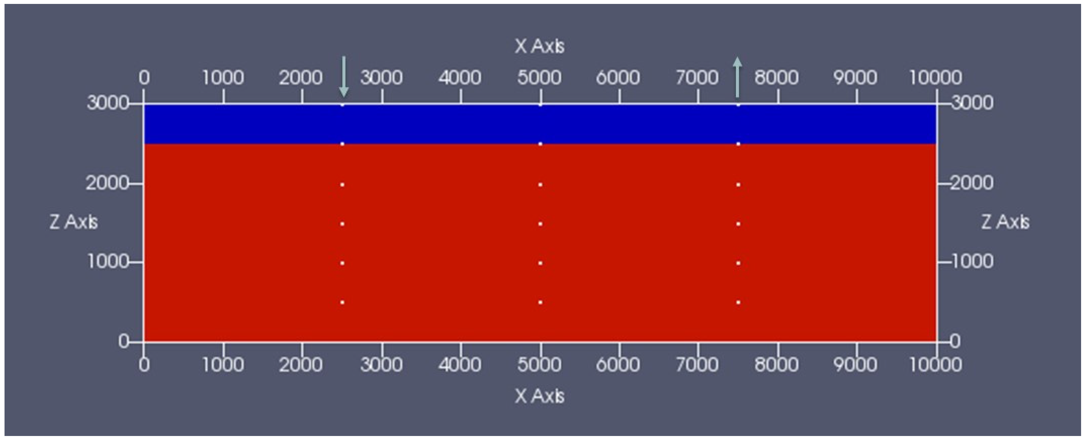
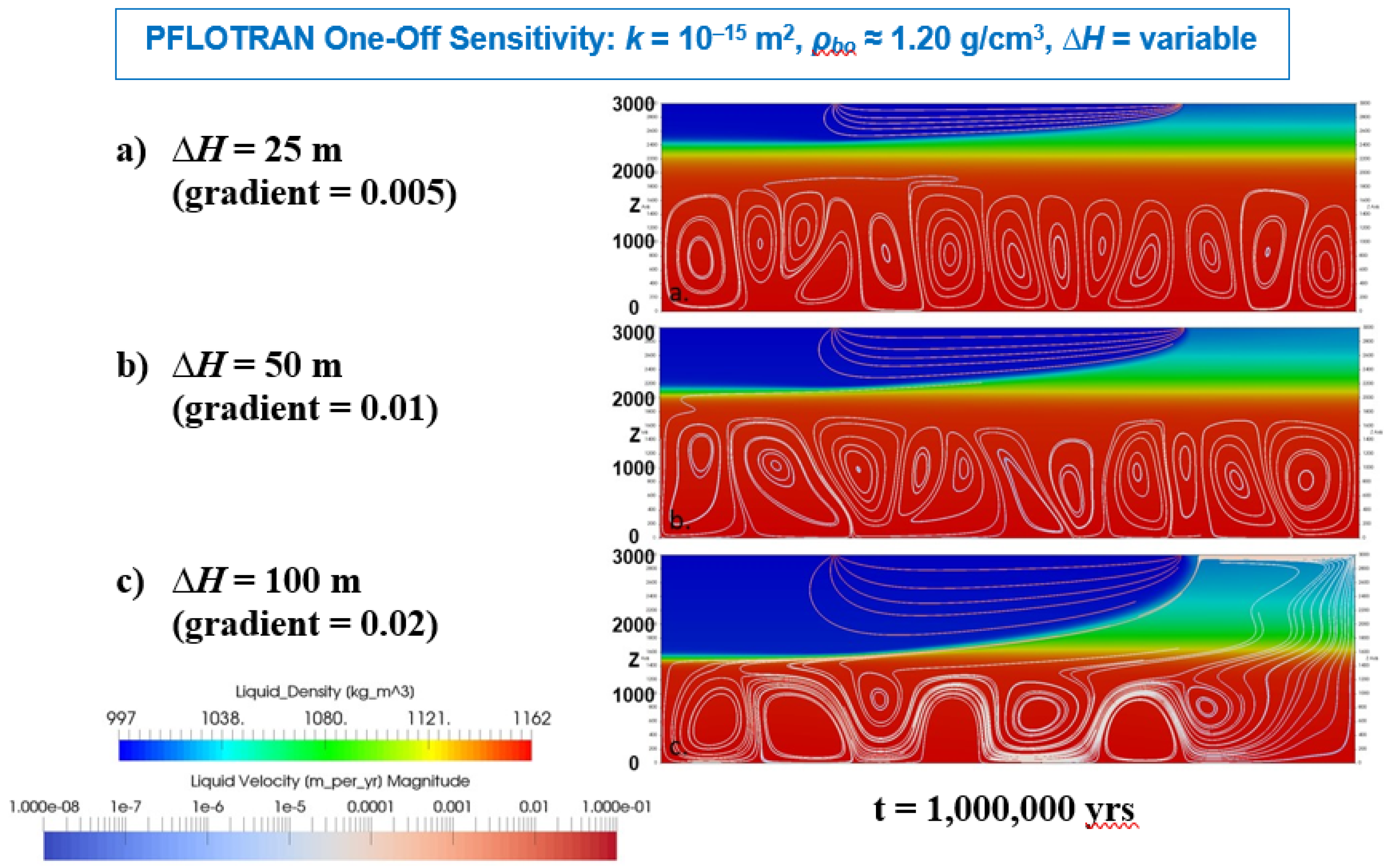
5.1.1. Regional-Scale Simulations

The PFLOTRAN regional-scale model domain (Figure 2) was the same as the 2D domain used by Park et al. [24], with a horizontal length of 10,000 m and a depth of 3000 m. The domain was discretized into 10 m by 10 m grid cells to produce a grid 1000 cells long by 300 cells deep (this discretization is finer than the 100 m by 100 m cells used by Park et al. [24].
Initial pressure was calculated as a fresh water hydrostatic gradient. Initial tracer concentration (Ct), representing salinity, was stratified, with fresh water (Ct = 0.029 M, corresponding to ρo ≈ 1.00 g/cm3) from 0 to 500 m depth and brine (Ct = 4.45 M, corresponding to ρbo ≈ 1.20 g/cm3) from 500 to 3000 m depth. This initial condition does not account for the effect of salinity on pressure, but does account for the effect of pressure on density. The actual chemistry of the brine is not considered in the model.
Tracer concentration is not held constant at any point in the model domain, allowing the salinity to evolve with time as it does in the allochthonous (isolated recharge water) model described by Park et al. [24]. If tracer concentration were held constant at depths from 500 to 3000 m, consistent with the autochthonous (ongoing rock-water interaction) model, the ability of fresh water recharge to penetrate to depths greater than 500 m and “flush” out brine would be less than that observed in these simulations.
All model boundaries are no-flow except for two 100 m long regions on the top boundary of the domain. At these locations, constant pressure boundary conditions are applied to establish recharge (from x = 2450 to 2550 m) and discharge (from x = 7450 to 7550 m). The pressure difference between the two constant pressure boundaries establishes the regional hydraulic head difference (∆H). A constant concentration (Ct = 0.029 M, representative of fresh water) boundary condition is applied at the recharge boundary. At the discharge boundary, a zero-concentration gradient is applied, which allows advection of tracer across the boundary (out of the model domain), but no diffusion.
A set of PFLOTRAN simulations were run for comparison to the regional-scale allochthonous model results of Park et al. [24]. These included:
Base case simulation, with:
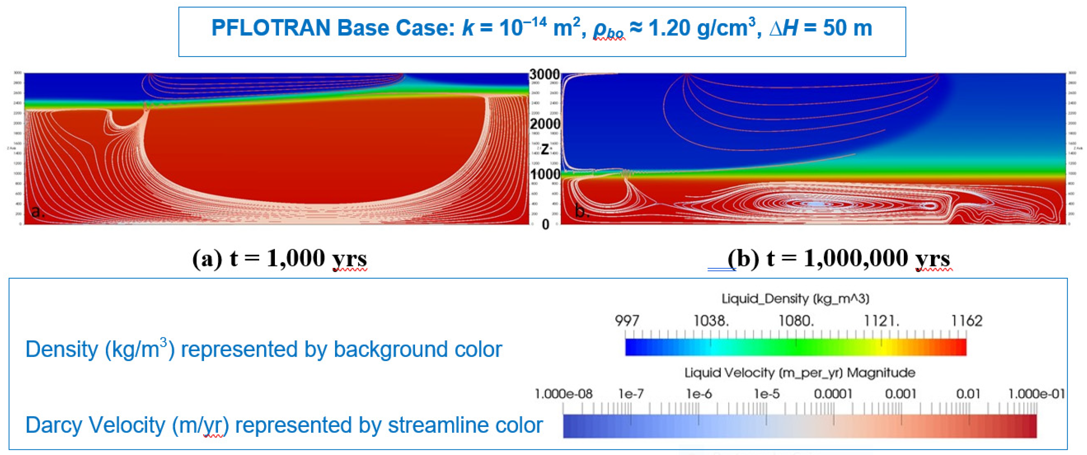
  • homogeneous rock properties: k = 10−14 m2 (intrinsic permeability), ϕ = 0.01 (porosity)
  • initial salinity at depth: Ct = 4.45 mol/L, to approximate brine density ρbo ≈ 1.20 g/cm3
  • hydraulic head difference: ∆H = 50 m, corresponding to a hydraulic head gradient of 0.01
Six one-off simulations, varying:
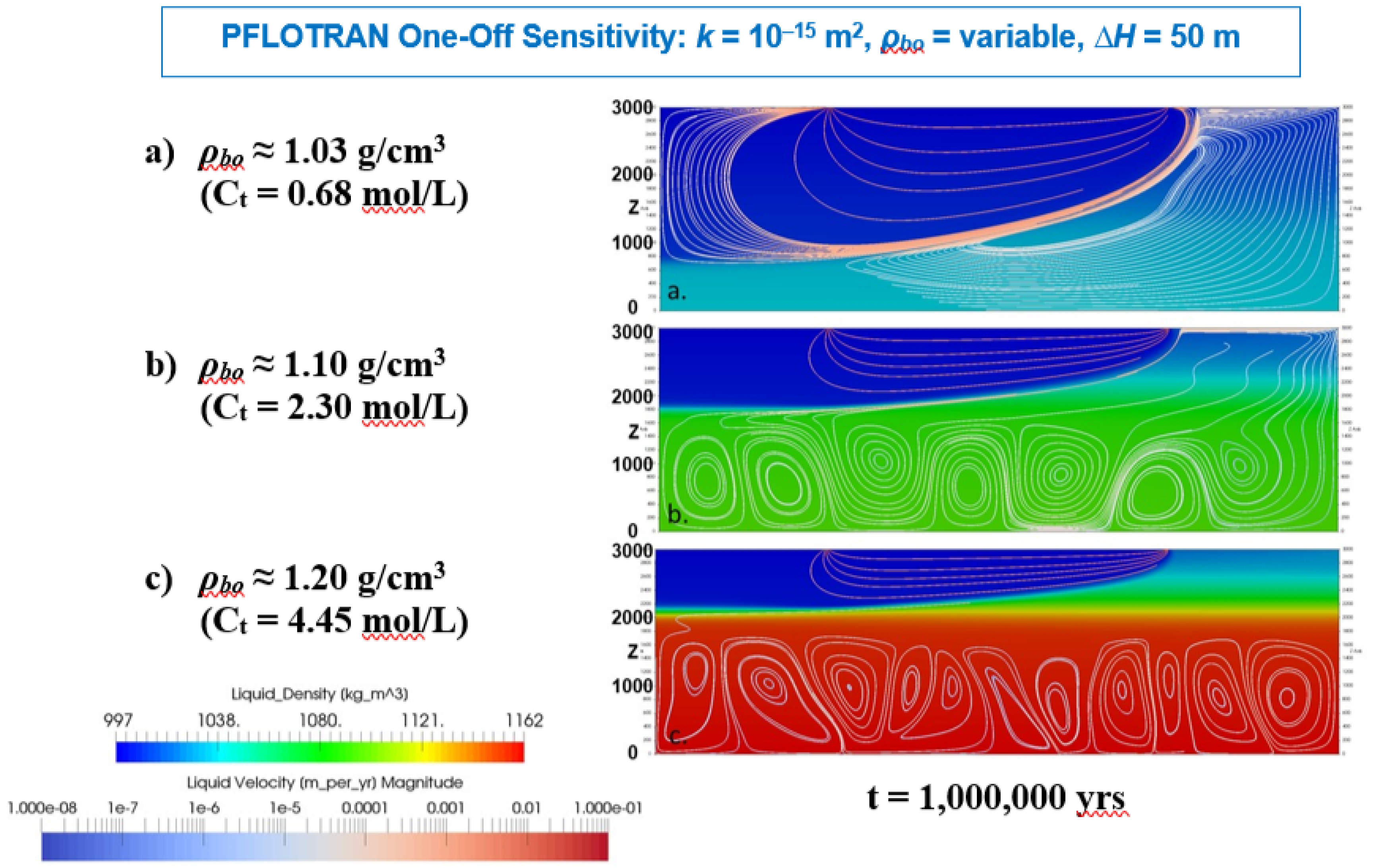
  • initial salinity at depth: Ct = 0.029, 0.68, and 2.3 mol/L at depth, corresponding to ρbo ≈ 1.00, 1.03, and 1.10 g/cm3, respectively
  • hydraulic head difference: ∆H = 25, 100, and 500 m, corresponding to hydraulic head gradients of 0.005, 0.02, and 0.10, respectively
The base case permeability of 10−14 m2 selected by Park et al. [24] is representative of sedimentary limestone/sandstone or highly fractured crystalline rock [33]. However, it expected that overlying sediments would consist of both high and low permeability layers and that the deeper crystalline basement rock would have a lower permeability [8]. To examine the effect of lower permeability on deep vertical flow and mixing, a parallel set of seven simulations were run with a lower homogeneous permeability (k = 10−15 m2), including the same one-off variations in brine density and hydraulic head difference. The lower permeability of 10−15 m2 is still at the upper end of expected permeabilities in crystalline rock at depth [8], but provides a basis for comparison to the set of 10−14 m2 permeability simulations.
All regional-scale PFLOTRAN simulations were run to 1,000,000 years, with maximum 10-year time steps, sufficient to capture the behavior of the transient problem on a geologically relevant time-scale. This is an extension to the duration of simulations of Park et al. [24], which were only run to 1000 years. Regional-scale simulation results are presented below.

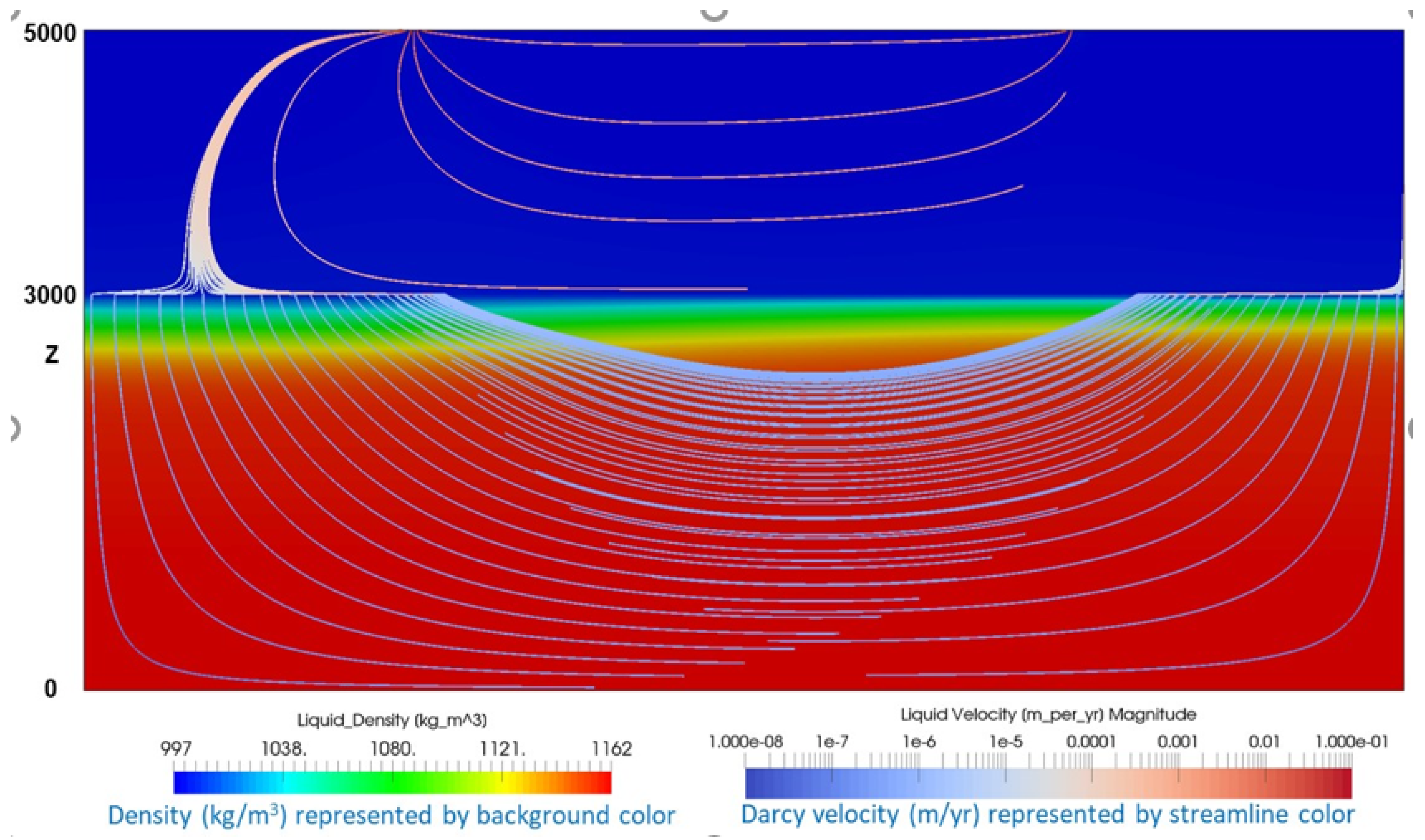
5.1.2. DBD-Scale Simulation

A single PFLOTRAN simulation with a DBD-scale model domain was also performed. The DBD-scale domain is more representative of depths and rock properties expected at a DBD site location. The DBD-scale domain is similar to the regional-scale model domain of Park et al. [24], with the following differences:
  • the domain is extended to a depth of 5000 m
  • the upper 2000 m (undifferentiated sediments) have k = 10−15 m2, ϕ = 0.20, and initial Ct = 0.029 mol/L (ρo ≈ 1.00 g/cm3)
  • the lower 3000 m (crystalline basement) have k = 10−18 m2, ϕ = 0.005, and initial Ct = 4.45 mol/L (ρbo ≈ 1.20 g/cm3)
These hydrogeologic properties are consistent with the DBD reference case from Freeze et al. [14]. The DBD-scale model domain is assumed to be isothermal at 25 °C, which is a difference from the geothermal gradient in the DBD reference case.

5.2. Model Results

5.2.1. Regional-Scale Model Domain

Results from the set of regional-scale PFLOTRAN simulations with a permeability of 10−14 m2 compared well with the allochthonous model results of Park et al. [24]. The results of the base case simulations (k = 10−14 m2, ρbo ≈ 1.20 g/cm3, ∆H = 50 m) at 1000 years [24] for PFLOTRAN are shown in Figure 3a. The base case PFLOTRAN results at 1,000,000 years is shown in Figure 3b.
By 1000 years in the base case, a flow path from the recharge boundary region to the discharge boundary region is established through the fresh water portion (i.e., above 500 m depth) of the domain. A semi-closed pattern of circulation is established in the deeper (initial brine) portion of the domain (seen best in Figure 3a). Although the top surface of the brine is disturbed by flow toward the discharge location, brine persists over most of the domain at depths greater than 500 m. By 1,000,000 years, however, the upper ~1800 m of the domain has been flushed with fresh water and circulation cells exist below that depth, with almost no mixing between the shallow fresh water and the deep brine (Figure 3b). This longer-term behavior was not evident from the short duration simulations of Park et al. [24].
PFLOTRAN results for the lower permeability base case (k = 10−15 m2, ρbo ≈ 1.20 g/cm3, ∆H = 50 m) are shown in Figure 4. As in the k = 10−14 m2 case, a flow path from the recharge boundary region to the discharge boundary region is established through the shallow (≤500 m depth) fresh water portion of the domain by 1000 years, but the semi-closed circulation pattern in the deeper brine has not yet been established (Figure 4a). By 1,000,000 years, the effects of the lower permeability are further apparent; only the upper ~800 m of the domain has been flushed with fresh water (Figure 4b); as compared to the 1800 m fresh water flushing depth for the k = 10−14 m2 case (Figure 3b). In addition, isolated circulation cells have been established at depth, with almost no mixing into the shallow fresh water.
The base case simulation results for k = 10−14 m2 and k = 10−15 m2 demonstrated density stratification behavior and vertical flow and mixing at depth under simplified hydrogeologic conditions. The one-off simulation results provide further insights into the flow behavior and its sensitivity to the regional hydraulic gradient (head difference) and initial brine density (tracer concentration). Selected results from the lower permeability (k = 10−15 m2) one-off simulations are described below.
Figure 5 compares 1,000,000-year PFLOTRAN results using 3 different initial brine densities (ρbo ≈ 1.03, 1.10, and 1.20 g/cm3) in the lower permeability case (k = 10−15 m2, ∆H = 50 m). With a homogeneous domain permeability of 10−15 m2, there is very little sensitivity to initial brine density in the first 1000 years; therefore, a comparison of 1000-year PFLOTRAN results is not shown. In all cases the flowlines have been established from recharge location to discharge location, but fresh water penetration (brine flushing) below 500 m depth is minimal.
By 1,000,000 years, the effect of initial brine density is apparent; low-density brine is more easily displaced than high-density brine. With lower-density brine (ρbo ≈ 1.03 g/cm3 (Ct = 0.68 M)), fresh water has flushed the brine to a depth of ~2200 m (Figure 5a). With moderate-density brine (ρbo ≈ 1.10 g/cm3 (Ct = 2.3 M)), fresh water has flushed the brine to a depth of ~1100 m (Figure 5b). And with the base case higher-density brine (ρbo ≈ 1.20 g/cm3 (Ct = 4.45 M)), fresh water has only flushed the brine to a depth of ~800 m (Figure 5c). For the cases with denser brine (ρbo ≥ 1.10 g/cm3), a deep circulation system has developed within the brine region.
Figure 6 compares 1,000,000-year PFLOTRAN results using 3 hydraulic head differences (∆H = 25, 50, and 100 m) in the lower permeability case (k = 10−15 m2, ρbo ≈ 1.20 g/cm3). These head differences applied over the 5000 m distance between recharge and discharge locations result in regional hydraulic head gradients of 0.005, 0.01, and 0.02, respectively. With a homogeneous domain permeability of 10−15 m2, there is very little sensitivity to the regional hydraulic gradient in the first 1000 years; therefore, a comparison of 1000-year PFLOTRAN results is not shown. In all cases the flowlines have been established from recharge location to discharge location, but fresh water penetration (brine flushing) below 500 m depth is minimal.
By 1,000,000 years, the effect of the regional hydraulic gradient is apparent; increasing the hydraulic gradient, i, increases the depth to which fresh water recharge circulates. With a relatively small regional gradient (∆H = 25 m, i = 0.005), fresh water has only flushed the domain to a depth of ~550 m (Figure 6a). With the base case ∆H = 50 m (i = 0.01), fresh water has flushed the domain to a depth of ~800 m (Figure 6b). And with a larger gradient (∆H = 100 m, i = 0.02), fresh water has flushed the domain to a depth of ~1400 m (Figure 6c). In all cases, a deep circulation system has been established in the brine region.
With an extremely large regional gradient (∆H = 500 m, i = 0.1), fresh water flushes the entire domain and flowlines from recharge location to discharge location extends down to 3000 m depth. However, these results are not shown, as this gradient is much larger than would be appropriate for a DBD site. For example, the hydraulic gradient assumed for a deep crystalline basement is 0.0001.
Simulations with k = 10−16 m2 and 10−18 m2 were also run; however, simulation results for these lower permeabilities are not shown, as they were nearly identical to the results with k = 10−15 m2.

5.2.2. DBD-Scale Model Domain

DBD-scale model results are shown in Figure 7. The 2000 m thickness of overlying undifferentiated sediments has a higher permeability (k = 10−15 m2) than the crystalline basement and an initial density of fresh water (ρo ≈ 1.00 g/cm3). As a result, flowlines from the fresh water recharge location to the discharge location circulate to the base of the sediments. Darcy fluxes in the sediments are on the order of 10−3 m/yr.
Basement permeability (k = 10−18 m2) is sufficiently low that significant advection does not develop in the deep basement brine. Instead, the recharge and discharge boundary conditions drive fluxes in the basement that are 3 to 4 orders of magnitude smaller than fluxes in the sediments, insufficient for significant fresh water flux into the basement. There is a small amount of mixing at the fresh water-brine interface, but no fresh water flushing of brine in the basement; with these properties, the density stratification of the brine remains for 1,000,000 years.
Darcy velocities are ~3 × 10⁻³ m/yr for the fresh water in the sediments and ~4 × 10⁻⁶ m/yr for the brine in the crystalline basement. One of the key results of the calculations above is that the salinity gradient resisting upward movement from deep boreholes will be persistent, an important component of the safety case for deep borehole disposal.

6. Borehole Sealing

DBD is a multi-barrier disposal concept which relies primarily on the great depth of disposal and the isolation provided by the natural geological and hydrogeochemical environment [34,35]. This contrasts with the shallower mined repository concepts in which the role of engineered barriers in the overall safety case is greater. If the isolation from the biosphere and surface environment provided by the deep natural barriers is not to be compromised, it is essential that the DBD seals limit and/or delay radionuclide migration from the waste packages in the EZ to the overlying sections of the borehole. This is necessary to prevent any possibility for the borehole itself, or the adjacent DRZ, to provide a transport path to the surface of less resistance than the surrounding geological barrier.
Most DBD designs advocate that the borehole is sealed as short a distance as possible above the topmost waste package in the EZ to maximize the depth of isolation. For the Cs/Sr capsule DBD reference design [14], the upper portion of the borehole includes the seal zone (SZ), where seals and plugs (bentonite seals, cement plugs, silica sand/crushed rock ballast) will be emplaced directly against the borehole wall, and the upper borehole zone (UBZ), where plugs (cement alternating with ballast) will be emplaced against the cemented casing. Seals in the SZ are designed to act directly against the DRZ of the crystalline basement host rock to inhibit vertical fluid flux and radionuclide transport up the borehole and through the DRZ. In the UBZ, the exact nature and distribution of seals, plugs, and/or backfill materials are dictated largely by the host geology, and so is site-specific. Seal materials may also contribute to thermal-hydro-chemical conditions that can limit and/or delay radionuclide transport, particularly in the SZ.
After the first few hundred years of maximum decay and heat production in the borehole, borehole temperatures are expected to return to ambient and there will be little driving force for upward movement of water. Further seal performance is desirable until re-establishment of the natural salinity gradient (density stratification), which tends to oppose upward flow; this period is assumed to be approximately 1000 years.
In the post-closure PA simulations presented in Freeze et al. [14], no performance credit is taken for processes in the EZ (e.g., waste form and waste package degradation, sorption in the EZ annulus). However, engineered waste forms, waste packages, and/or EZ annulus fill materials could further contribute to waste isolation and multi-barrier capability. Effective backfilling of the EZ annular regions (between (i) the waste packages and EZ liner, and (ii) the EZ liner and borehole wall) can prevent, or significantly delay, groundwater access to, and subsequent corrosion of, the waste packages. Backfilling of these EZ annular regions could also limit and/or delay the migration of radionuclides and H2 gas from corrosion out of the EZ. This could be achieved through the use of sealing and support matrices (SSMs) deployed along with the waste packages during emplacement in the EZ [36].
While seals, plugs, and backfill in the EZ and UBZ have the potential to further prevent and delay radionuclide release and migration, our focus here is on the performance, materials, and emplacement technology of the seals in the SZ.
Many versions of DBD, e.g., References [37,38,39] have looked to utilize the conventional man-made materials and systems developed by the oil and gas industry for sealing the boreholes. Others, recognizing the difficulties faced by these conventional methods, have proposed more innovative, albeit untested, methods. Among the latter are “rock welding” [35,40,41] and ceramic plugs [42].
Boreholes for the disposal of radioactive waste differ from hydrocarbon exploration and production wells, geothermal energy wells, and deep geoscientific boreholes in many key respects; not least in their depth-diameter combination and the fact that DBD boreholes are cased over a greater portion of their total depth. Moreover, in contrast to wells which are designed to extract resources or data over a limited period, DBD boreholes are intended to provide long-term isolation for potentially hazardous materials. Consequently, their sealing requirements are significantly different from those of exploration and production wells, although some commonalities may exist with plugging and abandoning exhausted or terminated wells.

6.1. Performance Targets

For any borehole sealing technology, seal emplacement must be relatively straightforward and reliable and seal longevity must be consistent with regulatory and/or post-closure performance requirements. Seal materials should be designed to have low permeability, bond effectively to the surrounding borehole wall and DRZ, and be resistant to thermal, chemical, and mechanical alteration which might degrade seal performance. These key performance targets for DBD sealing materials and technologies are summarized below.
Ideally, borehole seals should provide complete and permanent isolation of the EZ, preventing liquids and gases from flowing upwards through the borehole and its associated DRZ more easily than through the surrounding geological barrier. However, for any such upward flow to occur two conditions must exist. Firstly, there must be a driving force for the upward flow. Secondly, the engineered barriers (e.g., seal systems) and natural barriers (e.g., density stratification of brine) to flow up the borehole must have been removed or the force must be sufficient to disrupt them.
The most likely (perhaps only) significant force producing upward fluid flow in and around the borehole is buoyant convection driven by the decay heat from the waste in the EZ. Thermal modeling [8,43] shows that sufficiently elevated temperatures in and around the EZ would only be sustained for between a few hundred to a few thousand years, after which any thermally-driven buoyant convection would effectively cease. Modeling also suggests that during this period, waste from the EZ would be transported upwards, by advection, by only a few hundred meters, due largely to the low hydraulic conductivities, and hence the overall isolation of the waste would not be threatened, even in the absence of seals.
Natural barriers to upward flow in and around the borehole come from the low permeability of the host rock and the density stratified groundwaters (fresh water near the surface and concentrated brine at depth), both of which are disrupted or perturbed by the drilling of the borehole and activity during the operational phase. Once the latter ceases, the low permeability can be re-created by the sealing materials in the SZ and the regional groundwater density stratification (salinity gradient) will be restored by natural forces.
Assuming the thermally-driven buoyant convection is strong enough to temporarily disrupt the natural barrier in the borehole, a safety case would require that the seals outlast the thermal pulse, which is a function of the time required for the decay heat production to dissipate (and is dependent on the waste inventory). For the Cs/Sr capsule DBD reference case, the time needed for the thermal pulse to subside and buoyant convection to cease is on the order of a few hundred years [8]. For spent nuclear fuel, where decay heat is largely governed by the same short-lived radionuclides (90Sr and 137Cs), the time scale is on the order of 500 to 1000 years [39].
Once the driving force for upward movement of ground water has dissipated, further seal performance is desirable until re-establishment of the natural salinity gradient, which tends to inhibit vertical flow or mixing. Therefore, an additional consideration governing the desired longevity of the borehole seals is the time required for re-establishment of the natural density stratification of groundwater within and around the borehole. This period is assumed to be approximately 1000 years [8], with a bounding value of 10,000 years based on a simplified analytical solution [44]. Numerical modeling work is underway at the University of Sheffield to refine this bounding estimate. It is also worth noting that this time could possibly be reduced by appropriate choice of the closure fluids in the borehole (i.e., having salinity similar to the natural gradient).
Sealing emplacement methods must be as reliable as possible and the seals themselves must have as low a risk of failure as is reasonably practicable. Borehole seals should be resistant to thermal, chemical, and mechanical alteration under the anticipated range of downhole temperatures, pressures, and geochemical conditions.
Temperature—There are two main contributions to the temperature within the EZ in DBD: The semi-permanent geothermal gradient and the highly transient radioactive decay heat from the waste. Ambient temperatures, due to the natural geothermal gradient, typically 25–30 °C/km, are on the order of 140 °C at 5000 m depth (i.e., at the bottom of the EZ). Maximum temperatures in the EZ may be as high as 240 °C in the waste package and 200 °C at the borehole wall for Cs/Sr capsule disposal [8]. However, maximum temperatures in the seals, above the EZ, are likely to be much closer to ambient, on the order of 85 °C at 3000 m depth.
Pressure—The sealing method and materials used at depths up to 4 km should be capable of performing their functions under hydrostatic pressures of up to 40 MPa, with appropriate safety margins. Also, load stresses from any overlying materials in the borehole could increase the pressure by a few MPa, although this effect can be mitigated through the use of SSM and engineering design (e.g., bridge plugs).
Groundwater Chemistry—Borehole seals must perform in a hostile chemical environment in which the brines present at the depths relevant to DBD (3–5 km) will be dominated by Na, Ca and Cl with the Ca/Na ratio probably increasing with depth. Seals should be able to operate in groundwaters with TDS of at least 200 g/L.
As mentioned previously, resistance to flow and transport through the borehole seals is especially important during the first few hundred to few thousand years of thermally-driven buoyant convection, after which slow diffusion is the predominant transport mechanism.
Seal Permeability and Porosity—The low permeability of seal materials (bentonite and cement) inhibits vertical fluid flux and radionuclide advection up the borehole. An overall permeability, taking into consideration degradation processes, of 10−18 m2 is desirable, which should provide a more than adequate safety margin against any escaped radionuclides reaching the surface via the borehole, especially when the natural restoration of the groundwater barriers in and around the borehole is taken into consideration. Low porosity of seal materials corresponds to lower diffusion coefficients.
Seal Sorption—Seal materials may be selected for specific chemical characteristics. For example, the high sorption capacity of bentonite limits and/or delays radionuclide transport. Also, the presence of cement plugs can minimize chemical interaction between adjacent seals.
Disturbed Rock Zone Extent—The DRZ is an unavoidable consequence of drilling deep boreholes, the mechanical effects of which create a zone of fractured rock beyond the borehole wall. Any sealing method proposed for DBD should ideally extend to the DRZ, significantly reducing its permeability or eliminating it altogether, to avoid radionuclides circumventing the engineered seal.

6.2. Materials

The majority of existing sealing methods in the hydrocarbon and geothermal industries are based on inorganic, man-made, setting materials, such as cement and concrete, although other methods utilize swelling materials (e.g., clays) and mechanical packers, resins and asphalt.

6.2.1. Cements

There is a long history of sealing oil and gas and geothermal boreholes with cement, though the great depth of a disposal borehole poses emplacement challenges [8]. Cement pastes that are designed to thicken and set quickly problems for emplacement in a deep borehole, particularly in DBD, where the high temperatures and elevated pressures accelerate the thickening and reduce setting time. Additives can be employed to delay this process, but identifying and optimizing the most appropriate types and quantities are still active areas of research for DBD. To date, organic additives have been demonstrated that can delay grout thickening by at least 4 h (sufficient for DBD), but no longer than 24 h, at temperatures up to 140 °C and at elevated pressure (50 MPa) [36]. Retardation of thickening time using inorganic additives has also been proven, but they currently do not perform as well as organic materials across the range of elevated temperatures and pressures likely to be experienced in DBD.
A problem for cement-based seals for deep boreholes relates to emplacement: It is very difficult to deliver the cement to where it is needed and to form a good, continuous seal free from micro-annuli without premature setting and hardening. The cement slurry must be capable of being pumped at depth under high pressure conditions and to fill all the void space. Reverse circulation methods can improve the emplacement process, but significant challenges remain.
The formation of a good bond with the borehole wall rock is essential, but very difficult to achieve in practice. Great care must be taken to remove any drilling fluid and wall cake prior to emplacement of the cement, due to their chemical incompatibility. The operation to remove the drilling fluid by flushing with chemicals is also problematic and, if not done correctly, can itself lead to poor bonding of the cement to the wall rock.
As the rock formation relaxes, it can strip away water from the cement (forming a “thief” zone) and lead to shrinkage and a loss of water of hydration. Fluid loss additives to minimize this effect are often insufficient and can lead to decreased compressive strengths in the hardened cement paste. Experience gained from geothermal well cementing, which is often characterized by high temperatures and hostile chemical environments (usually acidic), illustrates this problem. Flash setting of the cements and a reduction in well lifetime are two of the more serious consequences. Introducing additives to the cement, pre-quenching of the wells, and remedial cementing, while possible (albeit difficult) in geothermal wells, are not really an option in DBD. With continued research into deep emplacement methods, cement plugs can be a useful component of DBD seal systems.

6.2.2. Bentonite and Other Clay-Based Systems

Bentonite expands in contact with water, has a high surface area, is routinely used to seal oil and gas and geothermal boreholes, and has been extensively studied as an engineered barrier in mined repositories [8]. Bentonite (altered volcanic ash with a high content of smectite clay) and other clays are characterized by extremely low permeabilities and self-healing properties, making them good candidates for seal materials. Their ability to expand on contact with water—an advantage when used as a seal—is a disadvantage when it comes to emplacement of the material in a fluid filled borehole. Various methods have been proposed for overcoming this problem when emplacing clay-based materials in boreholes, including those for DBD. The most promising method appears to be that involving emplacement of solid smectite blocks within perforated copper or bronze supercontainers [45]. However, this method may not work well in practice for DBD, due to the possibility of the supercontainers becoming jammed because of the small clearances. A different approach could entail the use of a specially developed dump bailer (used in hydrocarbon wells to deploy a measured quantity of cement) to emplace bentonite blocks while keeping them dry. In addition to these emplacement problems, other factors point to clays being a less than an optimum choice for use as seal materials in DBD. These include (i) the need to keep the clay hydrated, (ii) the potential for interaction between the smectite clay and groundwater, which may lead to compositional and physical changes, and (iii) chemical interactions between the bentonite and other materials in the borehole, especially a cements and metallic materials. As with cement, continued research into deep emplacement methods for bentonite can make it a viable component of DBD seal systems.

6.2.3. Geopolymers

These are cement derivatives produced by alkali activation of Class C fly ash with a NaOH and sodium silicate solution. These materials are at an early stage of development, but show some promise measured against the criteria needed to function as a seal in deep boreholes. However, since they do not solve the DRZ problem, they are unlikely to be useful as the main seal barrier in DBD.

6.2.4. Silicone Rubber

Typically used in conjunction with cement to form gas-tight, well-bonded, seals in gas wells, these materials show little shrinkage, are temperature resistant up to 300 °C, and are able to withstand a wide range of chemical environments. Another advantage is that they can be used easily with coiled tubing equipment. In view of these properties, silicone rubbers are worthy of further investigation as a component of the seal system.

6.2.5. Asphalt

The black colored hydrocarbons that constitute asphalt, also known as bitumen, have some useful characteristics for use as sealing materials. They are insoluble in water, colloidal, chemically inert, ductile, and durable (on a geological timescale). Asphalts also exhibit thermo-plastic behavior and can soften in the temperature range 35 °C to 80 °C. On the downside, accurate emplacement of asphalt-based seals could be challenging in deep boreholes. Also, organic acids leaching from the asphalt might complicate predictions of long-term radionuclide transport because of their ability to form aqueous complexes with some cationic radionuclides.

6.2.6. Crushed Rock

Crushed rock has been used as a seal in hydrocarbon wells, often in conjunction with other granular materials, such as sand and clay, and has been advocated as a possible seal in investigation boreholes for mined repositories and for DBD [9,45]. While emplacement is relatively simple, ensuring a complete and continuous seal free of voids is not so. For this reason, crushed rock is unlikely to be a suitable choice for the main seals in DBD.

6.2.7. Sandaband®

This is a proprietary mineral-based sealing system consisting of a dry mixture of barite and bentonite with up to 75% of fine silica sand. When mixed with water, viscosifiers and dispersants, it behaves as a Bingham fluid allowing it to be pumped to where it is required, but then behaving like a solid when stationary. The ability to deform when the applied stress exceeds its yield strength gives this material a self-healing property which is useful in a sealing context. Other promising properties of this material include low permeability, resistance to shrinkage and fracture, and thermodynamic stability. Also, it is chemically inert and is expected to have good durability. On the negative side, emplacement is difficult (it must be kept isolated from other fluids in the borehole), it contains organic additives, there is limited documented evidence of its use in boreholes.

6.2.8. Ceramic Seals

One of the more promising methods that have been proposed for sealing DBD involves the use of ceramic plugs. A ceramic plug is emplaced within the borehole seal zone and expands upon ignition through a thermite reaction. The properties of these seals should be superior to those of cement-based seals in terms of durability and reduced permeability. It has been suggested that ceramic seals might penetrate into the DRZ, although this is likely to be only for a few millimeters at most and requires experimental validation. Ceramic-based seals show promise for use in a multiple-material-based seal zone and warrant further R&D.

6.2.9. Rock Welding

Rock welding uses downhole electric heating to partially melt and recrystallize crushed granite backfill and wall rock of the borehole into a “weld” similar in makeup to the native crystalline rock [40,41]. Rock welding can create a seal for DBD as strong and durable as the undisturbed host rock and eliminate the DRZ by annealing shut any radially extensive flow paths. A research program is underway at the University of Sheffield to investigate and develop rock welding and has already demonstrated that the concept is viable on the laboratory scale. However, further work is required to scale up the method for DBD and downhole trials, optimization and testing need to be undertaken.

6.2.10. DRZ Minimization

As noted earlier, any sealing method for DBD should ideally extend to the DRZ, reducing its permeability and/or vertical connectivity. The generic DBD design, proposes emplacing the seal materials directly against the host rock and DRZ for this purpose. However, with the exception of rock welding, and (to a lesser extent) ceramic seals, none of the materials described above is specifically designed to significantly penetrate into, or otherwise reduce, the permeability of the DRZ. Therefore, continued research is warranted into sealing emplacement methods and material properties that might minimize the DRZ effects.
More work is also needed to further investigate the nature and extent of the change in permeability arising from the DRZ. It is possible that relaxation and stress relief, if largely confined to crystal boundaries in the crystalline host rock, would not impair the effective seal to a degree that would be of serious concern. However, until this is proven it has to be assumed that the DRZ is a possible conduit for the upward flow of fluids.
In summary, many types of seals should work in deep boreholes and multiple seals will likely be used in the sealing strategy. Because multiple seals would act in series, only one need be effective to increase confidence in the safety case. That being said, further R&D on seals would add to the safety case as well.

7. Conclusions

This paper outlines the assessment basis and safety assessment aspects of a deep borehole disposal safety case. The pre-closure and post-closure safety assessments, augmented by confidence enhancement analyses, collectively suggest that the DBD concept is a viable approach for safe disposal of radioactive wastes. The safety case presented here is specific to the disposal of Cs/Sr wastes, but is generally applicable to other waste forms, such as spent nuclear fuel. For example, the safety case for disposal of spent fuel would require an explicit analysis of fuel degradation and solubility controls over radionuclide release. Analysis of degradation rates of waste packages would add to the safety case for all waste types and add to the safety margin and confidence enhancement for deep borehole disposal. Adequate performance of borehole seals is less important if waste packages can be demonstrated to remain intact beyond the early thermal pulse from the decay of short-lived radionuclides.

Author Contributions

Conceptualization, G.A.F. and E.S.; formal analysis, G.A.F., E.S., C.L. and D.S.; writing—original draft preparation, P.V.B.; seals analysis; F.G., K.T. and J.B.

Funding

The research described in this paper was initiated as part of the U.S. Department of Energy (DOE) deep borehole field test (DBFT). DOE funding for the DBFT and other research related to deep borehole disposal was discontinued in 2017. Research subsequent to 2017, including the preparation of this paper, was funded by Sandia National Laboratories.

Acknowledgments

The authors would like to thank Mark Rigali for his technical review of the document and Laura Connolly for her help with document production and formatting. Sandia National Laboratories is a multimission laboratory managed and operated by National Technology and Engineering Solutions of Sandia, LLC., a wholly owned subsidiary of Honeywell International, Inc., for the U.S. Department of Energy’s National Nuclear Security Administration under contract DE-NA-0003525. This paper describes objective technical results and analysis. Any subjective views or opinions that might be expressed in the paper do not necessarily represent the views of the U.S. Department of Energy or the United States Government.

Conflicts of Interest

The authors declare no conflict of interest.

References

  1. Freeze, G.; Leigh, C.D.; Sevougian, S.D.; Gross, M. A Safety Framework for Disposal of Heat-Generating Waste in Salt: Annotated Outline. FCRD-USED-2012-000431, SAND2012-10797P; Sandia National Laboratories: Albuquerque, NM, USA, 2012. [Google Scholar]
  2. NEA (Nuclear Energy Agency). Methods for Safety Assessment of Geological Disposal Facilities for Radioactive Waste: Outcomes of the NEA MeSA Initiative. NEA No. 6923; Organisation for Economic Co-operation and Development, Nuclear Energy Agency: Paris, France, 2012. [Google Scholar]
  3. NEA (Nuclear Energy Agency). Confidence in the Long-term Safety of Deep Geological Repositories: Its Development and Communication; Organisation for Economic Co-operation and Development, Nuclear Energy Agency: Paris, France, 1999. [Google Scholar]
  4. NEA. Communicating Confidence in the Safety of Deep Geologic Disposal: Approaches and Arguments; OECD/NEA: Paris, France, 2002. [Google Scholar]
  5. NEA (Nuclear Energy Agency). Post-Closure Safety Case for Geological Repositories, Nature and Purpose. NEA Report No. 3679; Organisation for Economic Co-operation and Development, Nuclear Energy Agency: Paris, France, 2004. [Google Scholar]
  6. Freeze, G.; Voegele, M.; Vaughn, P.; Prouty, J.; Nutt, W.; Hardin, E.; Sevougian, S. Generic Deep Geologic Disposal Safety Case, SAND2013-0974P, REV 1; Sandia National Laboratories: Albuquerque, NM, USA, 2013. [Google Scholar]
  7. Arnold, B.W.; Brady, P.; Altman, S.; Vaughn, P.; Nielson, D.; Lee, J.; Gibb, F.; Mariner, P.; Travis, K.; Halsey, W. Deep Borehole Disposal Research: Demonstration Site Selection Guidelines, Borehole Seals Design, and RD&D Needs; SAND2013-9490P, Report for the US Department of Energy; Sandia National Laboratories: Albuquerque, NM, USA, 2013. [Google Scholar]
  8. Freeze, G.; Stein, E.; Price, L.; MacKinnon, R.; Tillman, J. Deep Borehole Disposal Safety Analysis. FCRD-UFD-2016-000075 Rev. 0, SAND2016-10949R; Sandia National Laboratories: Albuquerque, NM, USA, 2016. [Google Scholar]
  9. Freeze, G.; Stein, E.; Brady, P.V.; Lopez, C.; Sassani, D.; Travis, K.; Gibb, F. Deep Borehole Disposal Safety Case. SAND2019-1915; Sandia National Laboratories: Albuquerque, NM, USA, 2019. [Google Scholar]
  10. NEA (Nuclear Energy Agency). The Nature and Purpose of the Post-Closure Safety Cases for Geological Repositories, NEA/RWM/R(2013)1; Organisation for Economic Co-operation and Development, Nuclear Energy Agency: Paris, France, 2013. [Google Scholar]
  11. IAEA (International Atomic Energy Agency). The Safety Case and Safety Assessment for the Disposal of Radioactive Waste, Specific Safety Guide. IAEA Safety Standards Series No. SSG-23; IAEA: Vienna, Austria, 2012. [Google Scholar]
  12. Chapman, N.A. Who Might Be Interested in a Deep Borehole Disposal Facility for Their Radioactive Waste? Energies 2019, 12, 1542. [Google Scholar] [CrossRef]
  13. EPA (U.S. Environmental Protection Agency). EPA’s Environmental Radiation Protection Standards for SNF, H., and TRU Waste: Applicability of 40 CFR Part 191 to Deep Boreholes. Presented at the U.S. Nuclear Waste Technical Review Board International Technical Workshop on Deep Borehole Disposal of Radioactive Waste, Washington, DC, USA, 20–21 October 2015. [Google Scholar]
  14. Freeze, G.; Stein, E.; Brady, P.V. Post-closure Performance Assessment for Deep Borehole Disposal of Cs/Sr Capsules. Energies 2019, 12, 1980. [Google Scholar] [CrossRef]
  15. Hardin, E.L.; Clark, A.; Su, J.; Peretz, F. Preclosure Risk Assessment for Deep Borehole Disposal. Energies 2019. In Review. [Google Scholar]
  16. Hardin, E.L.; Clark, A.; Su, J.; Peretz, F. Preclosure Risk Assessment for Deep Borehole Disposal. SAND2019-1827; Sandia National Laboratories: Albuquerque, NM, USA, 2019. [Google Scholar]
  17. Kuhlman, K.L.; Brady, P.V.; MacKinnon, R.J.; Heath, J.E.; Herrick, C.G.; Jensen, R.P.; Gardner, W.P.; Sevougian, S.D.; Bryan, C.R.; Jang, J.-H. Deep Borehole Field Test Laboratory and Borehole Testing Strategy; Sandia National Lab.(SNL-NM): Albuquerque, NM, USA, 2016. [Google Scholar]
  18. Kuhlman, K.L.; Hardin, E.; Rigali, M.J. Deep Borehole Laboratory and Borehole Testing Strategy: Generic Drilling and Testing Plan; Sandia National Lab.(SNL-NM): Albuquerque, NM, USA, 2019. [Google Scholar]
  19. Frape, S.; Fritz, P.; McNutt, R. Water-rock interaction and chemistry of groundwaters from the Canadian Shield. Geochim. Et Cosmochim. Acta 1984, 48, 1617–1627. [Google Scholar] [CrossRef]
  20. Juhlin, C.; Wallroth, T.; Smellie, J.; Leijon, B.; Eliasson, T.; Ljunggren, C.; Beswick, J. The Very Deep Hole Concept-Geoscientific Appraisal of Conditions at Great Depth; Swedish Nuclear Fuel and Waste Management Co.: Stockholm, Sweden, 1998. [Google Scholar]
  21. Kietäväinen, R.; Ahonen, L.; Kukkonen, I.T.; Niedermann, S.; Wiersberg, T. Noble gas residence times of saline waters within crystalline bedrock, Outokumpu Deep Drill Hole, Finland. Geochim. Et Cosmochim. Acta 2014, 145, 159–174. [Google Scholar] [CrossRef] [Green Version]
  22. Gascoyne, M. Hydrogeochemistry, groundwater ages and sources of salts in a granitic batholith on the Canadian Shield, southeastern Manitoba. Appl. Geochem. 2004, 19, 519–560. [Google Scholar] [CrossRef]
  23. DeMaio, W.; Bates, E. Salinity and Density in Deep Boreholes. MIT Undergrad. Res. J. 2013, 26, 42–48. [Google Scholar]
  24. Park, Y.-J.; Sudicky, E.; Sykes, J. Effects of shield brine on the safe disposal of waste in deep geologic environments. Adv. Water Resour. 2009, 32, 1352–1358. [Google Scholar] [CrossRef]
  25. Phillips, S.; Igbene, A.; Fair, J.; Ozbek, H.; Tavana, M. A Technical Databook for Geothermal Energy Utilization; Lawrence Berkeley Laboratory, University of California: Berkeley, CA, USA, 1981. [Google Scholar]
  26. Holland, G.; Lollar, B.S.; Li, L.; Lacrampe-Couloume, G.; Slater, G.; Ballentine, C. Deep fracture fluids isolated in the crust since the Precambrian era. Nature 2013, 497, 357. [Google Scholar] [CrossRef] [PubMed]
  27. Bethke, C.M.; Johnson, T.M. Groundwater age and groundwater age dating. Annu. Rev. Earth Planet. Sci. 2008, 36, 121–152. [Google Scholar] [CrossRef]
  28. Aggarwal, P.K.; Froehlich, K.F.; Gat, J.R. Isotopes in the Water Cycle; Springer: Dordrecht, The Netherlands, 2005. [Google Scholar]
  29. IAEA (International Atomic Energy Agency). Isotope Methods for Dating Old Groundwater. STI/PUB/1587; IAEA: Vienna, Austria, 2013. [Google Scholar]
  30. Lippmann-Pipke, J.; Lollar, B.S.; Niedermann, S.; Stroncik, N.A.; Naumann, R.; van Heerden, E.; Onstott, T.C. Neon identifies two billion year old fluid component in Kaapvaal Craton. Chem. Geol. 2011, 283, 287–296. [Google Scholar] [CrossRef]
  31. Bottomley, D.J.; Gregoire, D.C.; Raven, K.G. Saline ground waters and brines in the Canadian Shield: Geochemical and isotopic evidence for a residual evaporite brine component. Geochim. Et Cosmochim. Acta 1994, 58, 1483–1498. [Google Scholar] [CrossRef]
  32. Lichtner, P.; Hammond, G. Quick Reference Guide: PFLOTRAN 2.0 (LA-CC-09-047) Multiphase-Multicomponent-Multiscale Massively Parallel Reactive Transport Code; DRAFT LA-UR-06-7048; Los Alamos National Laboratory: Los Alamos, NM, USA, 8 December 2012. [Google Scholar]
  33. Freeze, R.A.; Cherry, J.A. Groundwater; Prentice-Hall: Englewood Cliffs, NJ, USA, 1979. [Google Scholar]
  34. Chapman, N.; Gibb, F. A truly final waste management solution: Is very deep borehole disposal a realistic option for high-level waste or fissile materials. Radwaste Solut. 2003, 10, 26. [Google Scholar]
  35. Beswick, A.J.; Gibb, F.G.; Travis, K.P. Deep borehole disposal of nuclear waste: Engineering challenges. Proc. Inst. Civ. Eng. Energy 2014, 167, 47–66. [Google Scholar] [CrossRef]
  36. Collier, N.C.; Travis, K.P.; Gibb, F.G.; Milestone, N.B. Cementitious grouts for disposal of nuclear wasteforms in deep boreholes. In Proceedings of the American Nuclear Society International High-level Radioactive Waste Management, Charleston, SC, USA, 12–16 April 2015. [Google Scholar]
  37. Woodward-Clyde Consultants. Very Deep Hole Systems Engineering Studies; ONWI: Columbus, OH, USA, 1983. [Google Scholar]
  38. Arnold, B.W.; Brady, P.V.; Bauer, S.J.; Herrick, C.; Pye, S.; Finger, J. Reference Design and Operations for Deep Borehole Disposal of High-Level Radioactive Waste; SAND2011-6749; Sandia National Laboratories: Albuquerque, NM, USA, 2011. [Google Scholar]
  39. Arnold, B.W.; Brady, P.V.; Tillman, J. Deep Borehole Disposal of Nuclear Waste; Sandia National Laboratories: Albuquerque, NM, USA, 2013. [Google Scholar]
  40. Gibb, F.G.F.; Taylor, K.J.; Bukarov, B.E. The ‘granite encapsulation’ route to the safe disposal of Pu and other actinides. J. Nucl. Mater. 2008, 374, 364–369. [Google Scholar] [CrossRef]
  41. Gibb, F.G.; Travis, K.P. Sealing deep borehole disposals of radioactive waste by “rock welding”. In Proceedings of the 15th International High Level Radioactive Waste Management Conference, Charleston, SC, USA, 12–16 April 2015; pp. 12–16. [Google Scholar]
  42. Lowry, B.; Coates, K.; Wohletz, K.; Dunn, S.; Patera, E.; Duguid, A.; Arnold, B.; Zyvoloski, G.; Groven, L.; Kuramyssova, K. Ceramic Borehole Seals for Nuclear Waste Disposal Applications. In Proceedings of the AGU Fall Meeting Abstracts, San Francisco, CA, USA, 14–16 December 2015. [Google Scholar]
  43. Gibb, F.G.F.; Travis, K.P.; McTaggart, N.A.; Burley, D. Modelling temperature distribution around very deep borehole disposals of HLW. Nucl. Technol. 2006, 163, 62–73. [Google Scholar] [CrossRef]
  44. Travis, K.P.; Gibb, F.G.F.; Burley, D. Determining salinity recharge time for deep borehole disposal. In Proceedings of the Waste Management 2017 Conference, Phoenix, AZ, USA, 5–9 March 2017. [Google Scholar]
  45. Pusch, R.; Ramqvist, G.; Kasbohm, J.; Knutsson, S.; Mohammed, M.H. The concept of highly radioactive waste (HLW) in very deep boreholes in a new perspective. J. Earth Sci. Geotech. Eng. 2012, 2, 1–24. [Google Scholar]
Figure 1. Key Elements of a Safety Case (QA = Quality Assurance; NWPA = Nuclear Waste Policy Act; FEP = feature, event, and process; DRZ = Disturbed Rock Zone). Source: Freeze et al. [8].
Energies 12 02141 g001
Figure 2. Regional-Scale Model Domain and Initial Salinity Stratification cells used by Park et al. [24]) [Blue = initially fresh water (ρo ≈ 1.00 g/cm3)/Red = initially brine (ρbo ≈ 1.20 g/cm3)].
Energies 12 02141 g002
Figure 3. PFLOTRAN Base Case (k = 10−14 m2) Model Results (Fluid Density and Darcy Flux) (a) at 1000 years and (b) 1,000,000 years.
Energies 12 02141 g003
Figure 4. PFLOTRAN Base Case (k = 10−15 m2) Model Results (Fluid Density and Darcy Flux) (a) at 1000 years and (b) 1,000,000 years.
Energies 12 02141 g004
Figure 5. PFLOTRAN (k = 10−15 m2) Model Results (Sensitivity to Initial Brine Density) as a function of brine density; (a) 1.03 g/cm3, (b) 1.10 g/cm3, (c) 1.20 g/cm3.
Energies 12 02141 g005
Figure 6. PFLOTRAN (k = 10−15 m2) Model Results (Sensitivity to Hydraulic Head Difference) as a function of hydraulic gradient; (a) 0.005, (b) 0.01, (c) 0.02.
Energies 12 02141 g006
Figure 7. PFLOTRAN DBD-Scale Model Results (Fluid Density and Darcy Flux).
Energies 12 02141 g007
Table 1. Selected environmental tracers.
TracerHalf-Life (yrs)Groundwater Timescale (yrs)Dominant SourceOther Source(s)
δ2H/δ18On/a0.1–3Stable isotopes
3H/3Hen/a0.5–40Anthropogenic/Stable
85Kr10.721–40Anthropogenic
(nuc. industry)
CFCs, SF6n/a1–40Anthropogenic (manufacturing)
3H (tritium)12.31–50Anthropogenic
(bomb tests)
Cosmogenic
Anthropogenic (nuc. industry)
32Si~15050–1000Cosmogenic
39Ar26950–1000Cosmogenic
14C57301000–40,000CosmogenicAnthropogenic (bomb tests) Anthropogenic (nuc. industry)
4HeStable100–1,000,000Nucleogenic
81Kr210,00050,000–1,000,000Cosmogenic
36Cl301,00050,000–1,000,000CosmogenicAnthropogenic (bomb tests)
234U/238U245,500/4,468,000,00010,000–1,000,000Nucleogenic
129I15,700,0003,000,000–80,000,000Anthropogenic
(nuc. industry)
Anthropogenic (bomb tests) Cosmogenic
87Sr/86SrStable Radiogenic
Sources: Aggarwal et al. [28,29].

