Article

Modified Modeling and System Stabilization of Shunt Active Power Filter Compensating Loads with μF Capacitance

1
College of Electrical Engineering, Zhejiang University, Hangzhou 310027, China
2
Zhejiang Huayun Clean Energy CO., Ltd., Hangzhou 310002
3
University of Electronic Science and Technology of China, Chengdu 611731
*
Author to whom correspondence should be addressed.
Energies 2019, 12(11), 2084; https://doi.org/10.3390/en12112084
Submission received: 19 May 2019 / Revised: 28 May 2019 / Accepted: 29 May 2019 / Published: 31 May 2019

Abstract

:
The interactions between shunt active power filter (APF) and capacitance load tend to result in stability problems and resonance. The conventional model of a shunt APF is not precise enough to reflect this phenomenon. To address it, this paper proposes a modified shunt APF system model to accurately reflect various stability problems. This paper also studies the mechanism of positive feedback resonance brought by capacitance load and proposes a modified hybrid controller to improve the stable margin of the system, making the shunt APF work stably under different working conditions where there are μF capacitors on the demand side. The correctness and validity of the proposed strategy are verified by simulation analysis and prototype experiments.

1. Introduction

An active power filter (APF) is a power electronic device that deals with harmonics, three-phase unbalanced loads, and reactive power compensation in a distribution network [1,2]. In recent years, people have mainly focused on proposing new topologies and operation principles to enhance the harmonic compensation capability, reduce system size, or improve dynamic performance under load variation [3,4,5,6]. Researchers have also designed novel control strategies such as dynamic surface adaptive fuzzy controller [7], backstepping neural global sliding mode controller [8], adaptive fractional sliding mode controller [9], adaptive fuzzy global sliding mode control [10], and one-sixth fundamental period fast-transient repetitive controller [11] to obtain good control effects in stability, robustness, adaptability, or dynamic performance.
The topology structure of an active power filter can be divided into shunt APF topology and series APF topology. Since it is difficult for the series active power filter to protect against overcurrent, its application is very limited. Therefore, the shunt active power filter is the one widely used in industrial applications. Compensation characteristics of both shunt APFs and series APFs are analyzed under harmonic voltage or harmonic current sources in [12,13]. It is pointed out that harmonic current is amplified when shunt APFs are compensating harmonic voltage sources. The problem of harmonic amplification also exists when parallel capacitors are connected to a shunt APF system. The difference is that parallel capacitors cannot be considered to be ideal voltage sources with internal impedance close to zero. The mechanism of harmonic amplification is different from the one of harmonic voltage sources in [12,13]. At present, few papers focus on the resonance and system instability of a shunt APF system caused by parallel capacitors. Researchers generally agree that shunt APFs are used for compensating harmonic current sources. However, there are some small capacitors, such as for electromagnetic interference (EMI) suppression, power factor correction, reactive compensation, and starting a single-phase motor connected to a distribution network. They are very sensitive to harmonic voltage generated by an APF (which will be converted to current with the same amplitude as the load harmonic current but in the opposite phase) and will amplify it to a large harmonic current. Therefore, simplifying different loads to a harmonic current source will lead to instability problems when there are capacitors on the demand side. It is always a threat to the distribution system. Even recent studies have this problem (see Figure 6 in Section 2). Therefore, it is necessary to study this problem thoroughly. Conventional models of shunt active power filter focus only on APF itself, ignoring the dynamic characteristics of its input signal, the power grid, the loads, and the surrounding power electronic devices. The modelling of power electronic devices should not be isolated. The influence of a static VAR compensator (SVC) on power quality of photovoltaic plants has been noticed by scholars in [14,15]. In this paper, a more accurate model of active power filter, considering dynamic input signal, power grid, and loads will be proposed.
This paper is organized as follows: Section 2 introduces the conventional model of the shunt active power filter and points out its flaws. In Section 3 we propose a modified shunt APF model, analyze the mechanism of resonance, and decompose the complex stability problem into the instability of the external circuit and the inverter repetitive controller. In Section 4 we modify the hybrid repetitive controller to make the shunt APF work stably when there are μF capacitors on the demand side. In Section 5, simulation analysis and prototype experiments are carried out to verify our theory. Finally, Section 6 summarizes the results of the whole paper.

2. Problems of Conventional Model of Shunt APF

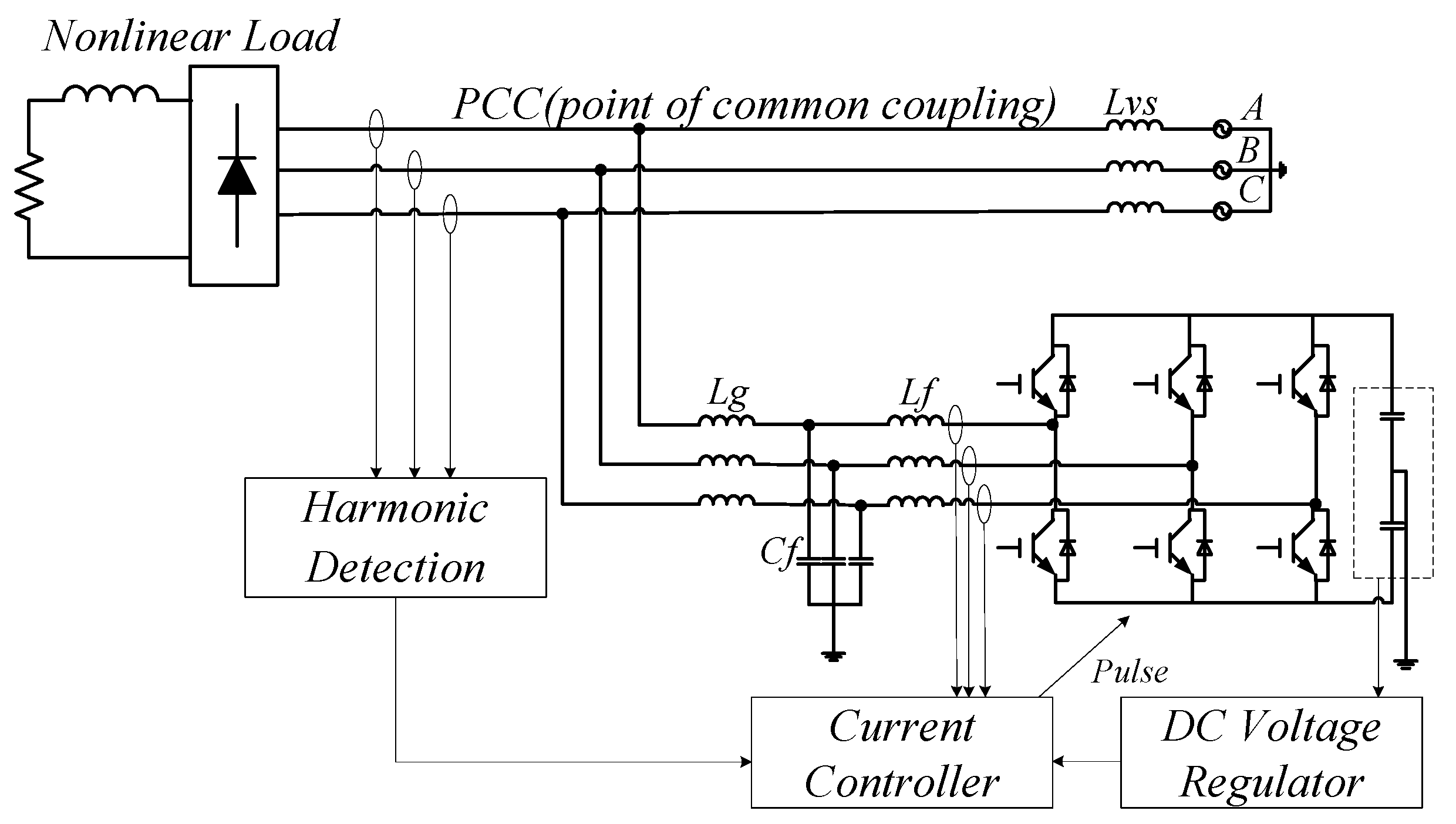
2.1. Review of Shunt Active Power Filter

As a commonly used direct current control strategy, the active power filter detects the harmonic, reactive, and unbalance components of the load current and generates an output current with the same amplitude but in opposite phase. Figure 1 illustrates the structure and control scheme of a three-phase, four-wire shunt active power filter system.

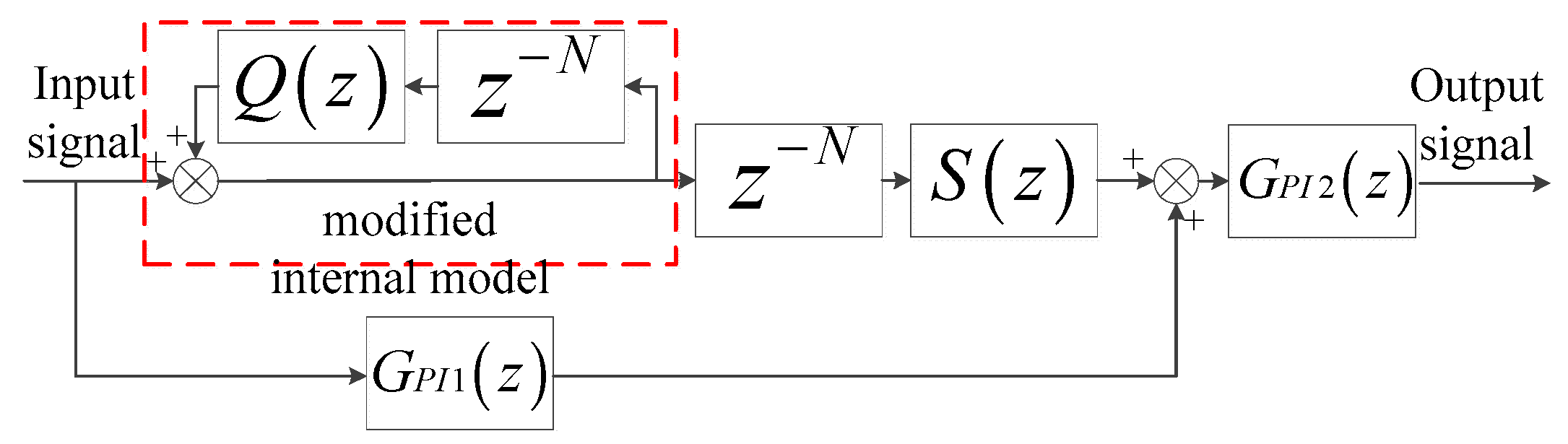
2.2. Review of Hybrid Repetitive Controller

The basic idea behind the repetitive controller is the internal model principle (IMP), which was first proposed in [16]. It was first used in active power filters to compensate for current harmonics in [17]. Now the repetitive control strategy has been improved and is quite mature [18,19,20].
The hybrid repetitive controller scheme is shown in Figure 2. The modified internal model denoted by the positive feedback loop is the core of the discrete controller. The period delay part z−N in the forward path causes a delay of one fundamental period, so that the controller has foresight of the next period. Due to the period delay part, the transient response of the repetitive controller is slow. To enable the repetitive controller to quickly respond to dynamic load changes, researchers add a parallel proportional-integral unit GPI1(z). To increase the system stability margin, researchers also use a filter Q(z) or an attenuation coefficient Q to modify the internal model instead of the unit gain. Proportional-integral units GPI1(z) and GPI2(z) are used to enlarge the stability range of the controller. A corrector S(z) is also used to ensure the stability of the repetitive controller. Its function is to provide amplitude and phase compensation and improve the correction effect.

2.3. Conventional Model and Stability Problem of APF

Researchers have extensively studied modeling and stability analysis of shunt active power filters [11,20,21,22,23,24]. A conventional model of a hybrid repetitive controlled shunt APF is shown in Figure 3. GLCL(z) reflects the output filter of external circuits. Its continuous domain transfer function is Equation (1).
G L C L ( s ) = L g C f s + 1 L f L g C f s 3 + ( L f + L g ) s
The sufficient criterion for stability analysis of digital repetitive controllers was first proposed in [22,23,24,25]. Its adequacy and necessity are proved in [25]. This method is further used to guide the design of APFs and to judge stability in [20,21,26,27,28]. According to the sufficient criterion for stability, the closed-loop transfer function from the reference R(z) to the error E(z), which is the sensitive function of the closed-loop controlled system, is Equation (2).
E ( z ) R ( z ) = 1 1 + G L C L ( z ) G P I 2 ( z ) [ z N S ( z ) 1 Q ( z ) z N + G P I 1 ( z ) ] = 1 Q ( z ) z N [ 1 + G L C L ( z ) G P I 2 ( z ) G P I 1 ( z ) ] { 1 z N [ Q ( z ) S ( z ) G L C L ( z ) G P I 2 ( z ) 1 + G L C L ( z ) G P I 2 ( z ) G P I 1 ( z ) ] }
Let
P ( z ) = G L C L ( z ) G P I 2 ( z ) 1 + G L C L ( z ) G P I 2 ( z ) G P I 1 ( z ) T ( z ) = 1 1 + G L C L ( z ) G P I 2 ( z ) G P I 1 ( z )
The sensitive function of the closed-loop system can be expressed as Equation (4).
E ( z ) R ( z ) = T ( z ) 1 Q ( z ) z N 1 z N [ Q ( z ) S ( z ) P ( z ) ]
The sufficient stability criterion of the shunt active power filter is as follows.
  • Transfer function T(z) does not have poles outside the unit circle.
  • H(z) = |Q(z)S(z)P(z)| < 1, z = ejωTs, ω ⸦ [0, π/Ts].
Table 1 lists the parameters of the digital repetitive controlled shunt active power filter. Applying the bilinear discretization method, transfer function T(z) is stable due to the active damper strategy of the LCL filter. A Nyquist diagram of H(z) is shown in Figure 4. According to the sufficient stability criterion, the shunt APF system is stable. In Figure 5, a current waveform of 0.6–0.8 s shows that the shunt APF can achieve good compensation performance under inductance load and three-phase rectifier load. However, when capacitance load (Cload(Y) and Cload(Δ) in Table 1) is connected in parallel at 0.8 s, the system becomes unstable.

2.4. Flaws of Conventional Model of Shunt APF

Researchers generally agree that a shunt APF can be used for compensating harmonic current sources. Therefore, the plant transfer function is established as GLCL(z), regardless of the transfer function of load and external circuit. The essence of the APF is to compensate the load harmonic current by the harmonic voltage generated by the voltage source inverter of the APF. For an inductance load following the law of iL = U/(jωL), it is insensitive to harmonic voltage. However, for a pure capacitance load following the law of iC = U*(jωC), it is very sensitive to harmonic voltage. The harmonic voltage at the point of common coupling (PCC) will be amplified to a large harmonic current. Therefore, the plant transfer function should be an overall modeling of the external circuit instead of a simple GLCL(z). After all, no one can guarantee that the load side will never be connected by parallel capacitors.
It is generally believed that the compensation capability of a well-designed active power filter should not change with different load conditions. Therefore, such devices are suitable for serialization and large-scale production. Conventional modeling of active power systems is limited by such thought.
Another flaw is the input command of the model. It is not a given value, but the output value of the load current after the harmonic detection unit, which is a dynamically changing command. The load current is the superposition of currents produced by system voltage and the APF’s inverter output voltage. In other words, the present output voltage of the APF inverter will affect its next input command. Therefore, the input command of the APF should not be used as the input command of the closed-loop control system in modeling. It should be an independent external value that is not affected by the change of state variables within the system.
The instability problem also exists in other APF controllers besides the repetitive controller. Recent research on improving the stability and robustness of digitally controlled active power filters by studying the systematic controller parameter design criterion and modifying the digital controller is presented in [24]. We repeated the simulation in that paper and found that the instability problem still exists. Figure 6 shows a simulated grid current of the repeated simulation of [24]. It can compensate inductance load and three-phase rectifier load well in 0–0.15 s. When capacitance load is connected in parallel at 0.15 s, the system soon becomes unstable.
As a summary, we list the flaws of the conventional model of a shunt APF in Table 2.

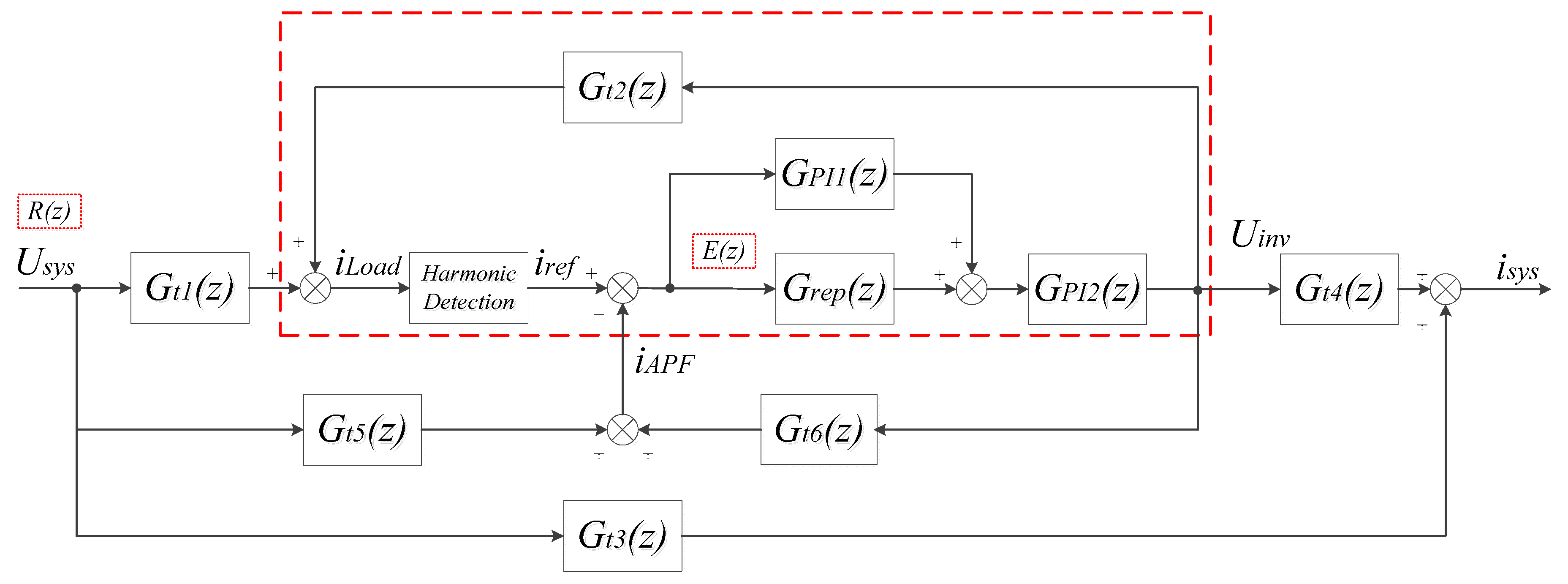
3. Modified Model of Shunt APF and its Stability Analysis

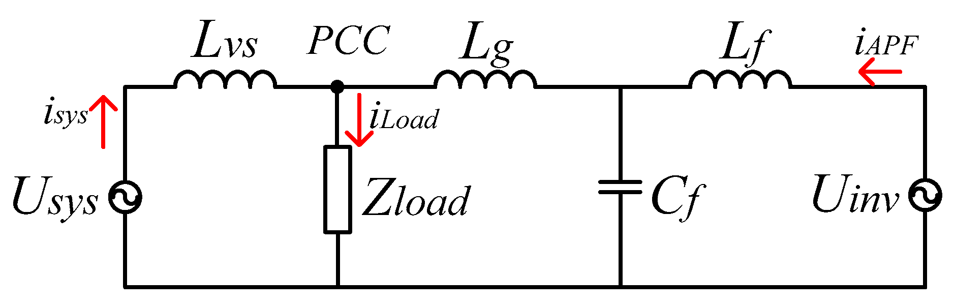
3.1. Modeling Shunt Active Power Filter

From the analysis in Section 2, we can conclude that the input command of the APF inverter should not be selected as the input command of the closed-loop system. Instead, we should choose the unique external variable, the voltage of the distribution system Usys, as the input command. When the voltage of the distribution system is given, the subsequent development of all state variables is known. A modified model of the shunt active power filter system is shown in Figure 7, where Isys represents the current injected into the distribution network, ILoad represents the current injected into the load side, and IAPF represents the current flowing out of the inverter port. Transfer functions Gt1Gt6 can be deduced in Equation (5) through the external circuit in Figure 8. Computation and pulse width modulation (PWM) delays of the inverter are neglected in the model. The harmonic detection algorithms include the application of instantaneous reactive power theory [29,30], synchronized rotating coordinate transform method [31,32], discrete Fourier transform (DFT) [33,34], etc. These algorithms are generally complex, highly three-phase coupled, and unsuitable for model analysis. In this paper, the harmonic detection unit is treated as a proportional component with coefficient 1 to reactive power, asymmetric, and harmonic current, and with coefficient 0 to the active component of the fundamental current. The following stability analysis is based on this approximation. The proposed model only includes three-phase resistors, inductors, and capacitors on the demand side. It does not include rectifier loads. That is because the rectifier load can be seen as a harmonic current source, and it can be well compensated by the shunt active power filter without stability problems [12,13]. In this way, the modeled system can be analyzed simply and clearly according to linear system theory.
i L o a d = U s y s G t 1 + U i n v G t 2 i s y s = U s y s G t 3 + U i n v G t 4 i A P F = U s y s G t 5 + U i n v G t 6

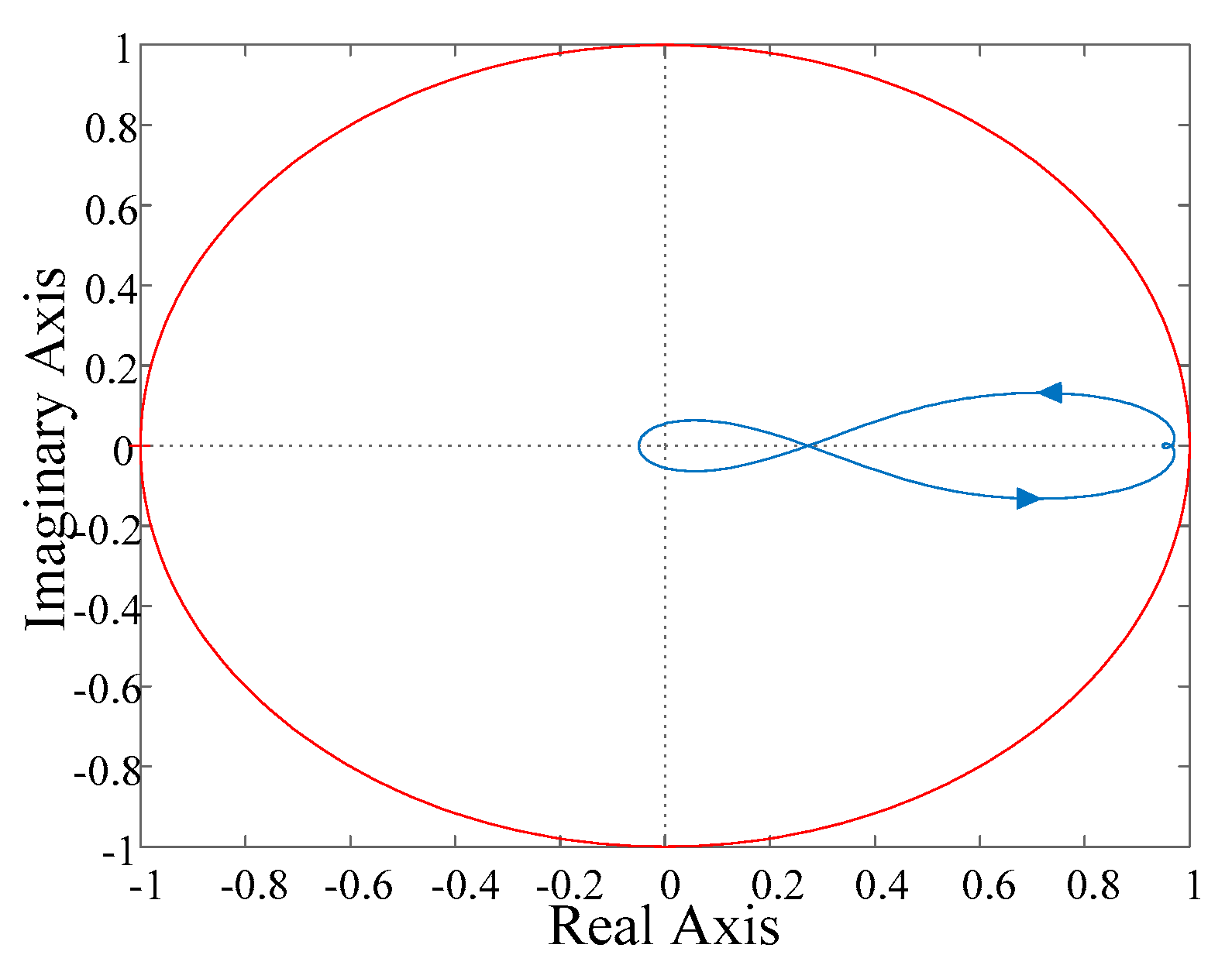
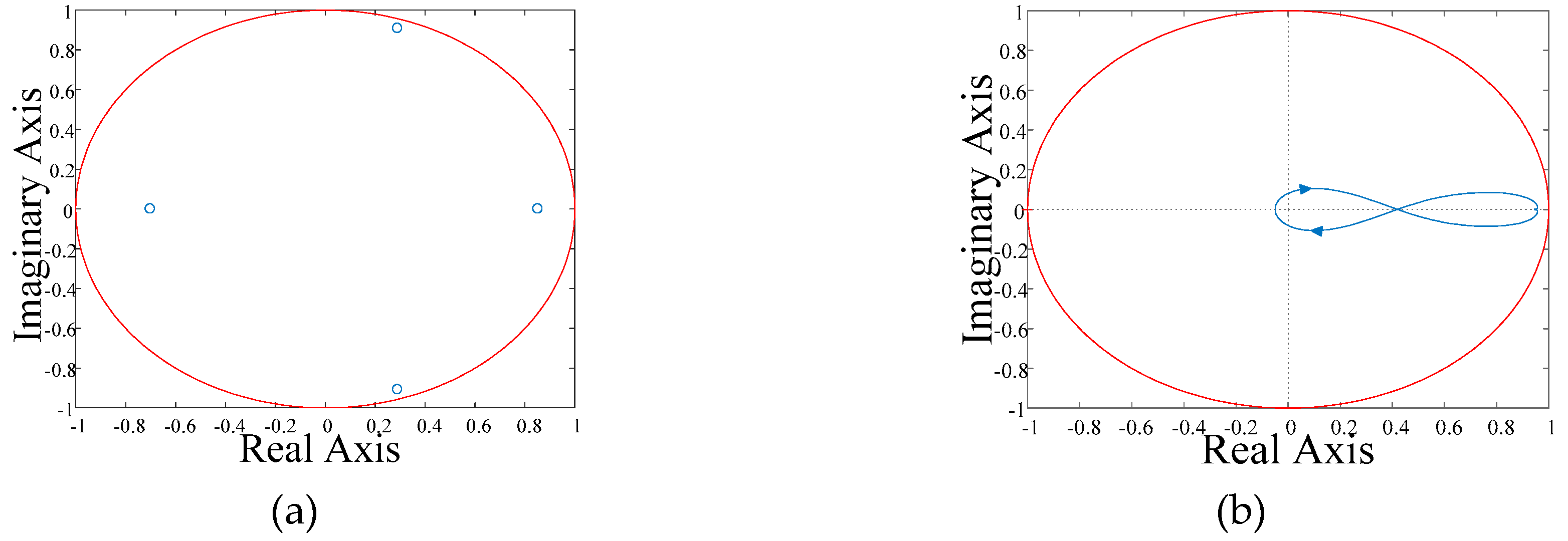
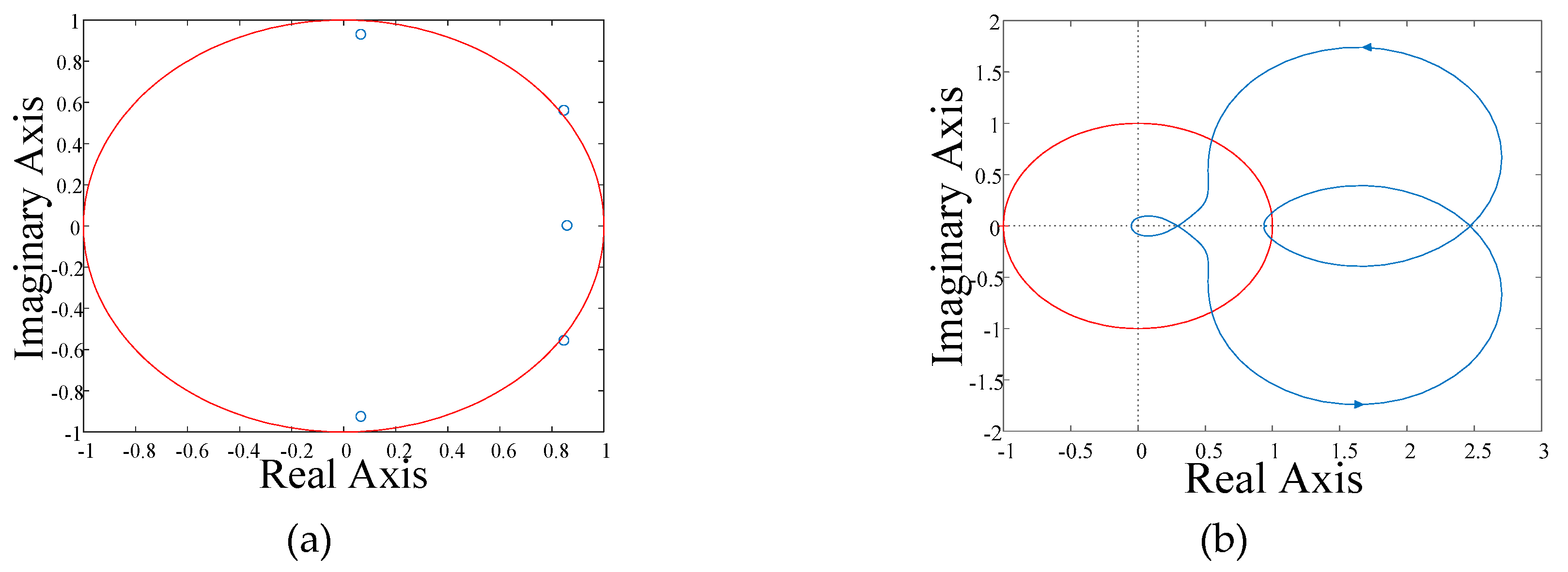
3.2. Stability Analysis of Shunt APF System

The sufficient stability criterion for the modified shunt active power filter system is deduced in Equation (6).
E ( z ) R ( z ) = G t 1 ( z ) G t 5 ( z ) 1 + [ G t 6 ( z ) G t 2 ( z ) ] G P I 2 ( z ) [ z N S ( z ) 1 Q ( z ) z N + G P I 1 ( z ) ] = [ G t 1 ( z ) G t 5 ( z ) ] [ 1 Q ( z ) z N ] { 1 + [ G t 6 ( z ) G t 2 ( z ) ] G P I 1 ( z ) G P I 2 ( z ) } { 1 Q ( z ) z N + z N S ( z ) [ G t 6 ( z ) G t 2 ( z ) ] G P I 2 ( z ) 1 + [ G t 6 ( z ) G t 2 ( z ) ] G P I 1 ( z ) G P I 2 ( z ) }
Let
P ( z ) = [ G t 6 ( z ) G t 2 ( z ) ] G P I 2 ( z ) 1 + [ G t 6 ( z ) G t 2 ( z ) ] G P I 1 ( z ) G P I 2 ( z ) T ( z ) = G t 1 ( z ) G t 5 ( z ) 1 + [ G t 6 ( z ) G t 2 ( z ) ] G P I 1 ( z ) G P I 2 ( z ) E ( z ) R ( z ) = T ( z ) 1 Q ( z ) z N 1 z N [ Q ( z ) S ( z ) P ( z ) ]
The sufficient stability criterion of the shunt active power filter is as follows:
  • Transfer function T(z) does not have poles outside the unit circle.
  • H(z) = |Q(z)S(z)P(z)| <1, z = ejωTs, ω ⸦ [0, π/Ts].
Applying the parameters from Table 1 and the bilinear discretization method to the system, a pole diagram of T(z) and a Nyquist diagram of H(z) are plotted to validate the correctness of the modified shunt APF model with sufficient stability criterion. Figure 9a,b shows load conditions under resistor–inductor (RL) load conditions (Rload = 4.4 Ω, Lload = 15 mH). Figure 10a,b shows load conditions under resistor–inductor–capacitor load conditions (Cload = 366.5 μF). Both sufficient stability criteria are satisfied in Figure 9 under RL load conditions. Neither of the two sufficient stability criteria is satisfied in Figure 10, which means the system is unstable under RLC conditions. They correspond well with the simulated grid current and stability condition in Figure 5. This proves that the modified model can reflect the actual shunt active power system well. Based on the modified model, we will analyze the mechanism of resonance in the shunt APF system under capacitance load conditions in next part.

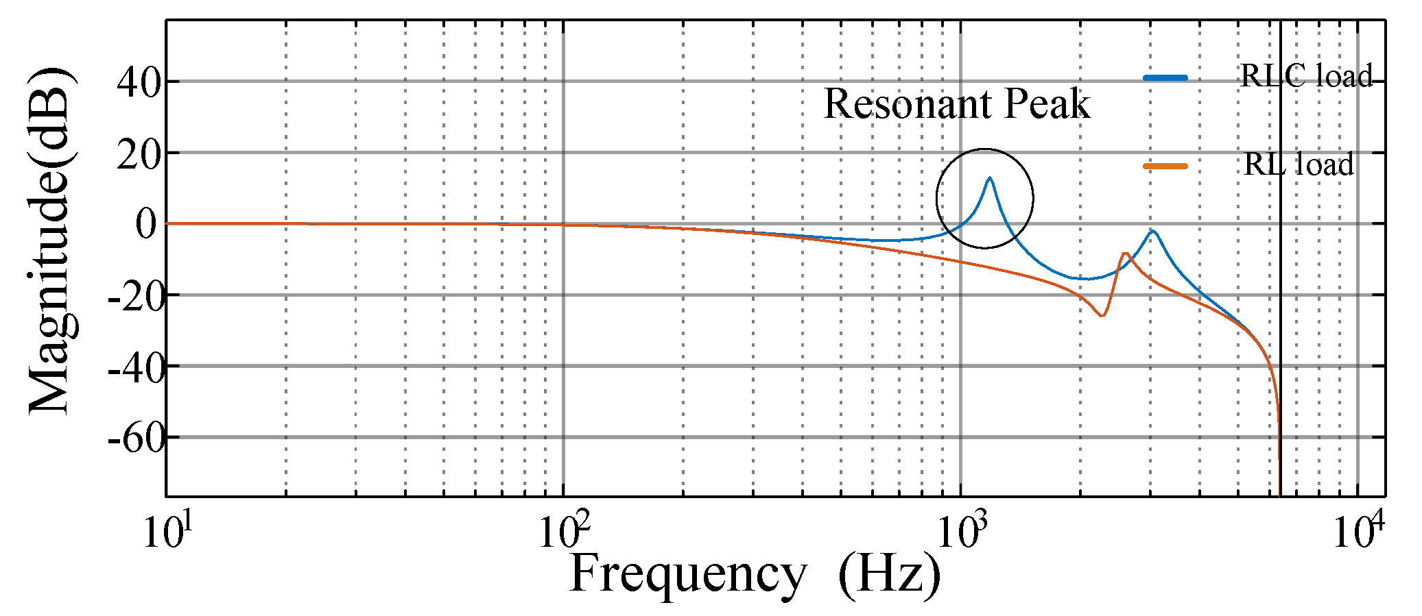
3.3. Mechanism of Resonance Under Capacitance Load

The resonance of the shunt active power filter system is due to the RLC parallel resonance circuit and the positive feedback effect of the APF system. There is a parallel resonance circuit among the capacitance load, inductance load, and system reactance. The harmonic detection unit extracts the resonant current flowing into the capacitance load and generates harmonic current with the same frequency, same magnitude and opposite phase. However, as a voltage source inverter, it actually generates voltage of resonant frequency. The resonant voltage is applied to the RLC parallel circuit and results in a larger parallel resonant current. The capacitor’s characteristic of being very sensitive to the voltage applied to it makes the resonant current greatly amplified. Owing to the dynamic response characteristics of the active power filter, a positive feedback path is formed, shown as the dotted box in Figure 7. The positive feedback intensifies the resonance and results in system instability.
According to the expression of sensitivity function (Equation (7)), unstable poles of the APF system come from T(z) and 1 − z−NH(z). The location of the poles of T(z) and the Nyquist diagram of H(z) are determined by the external circuit and controllers. Next, the impact of each part on system stability will be analyzed.

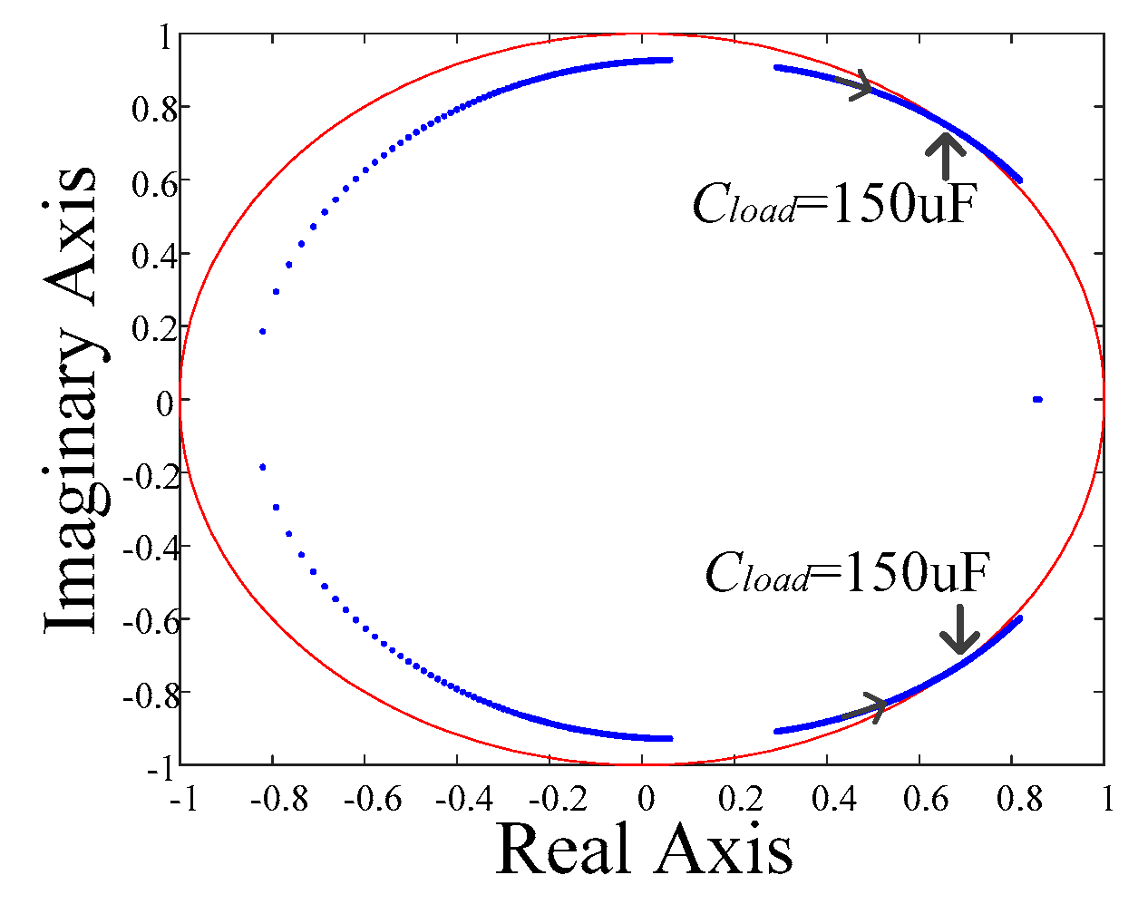
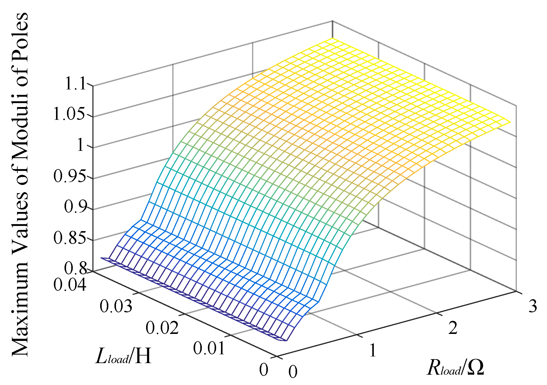
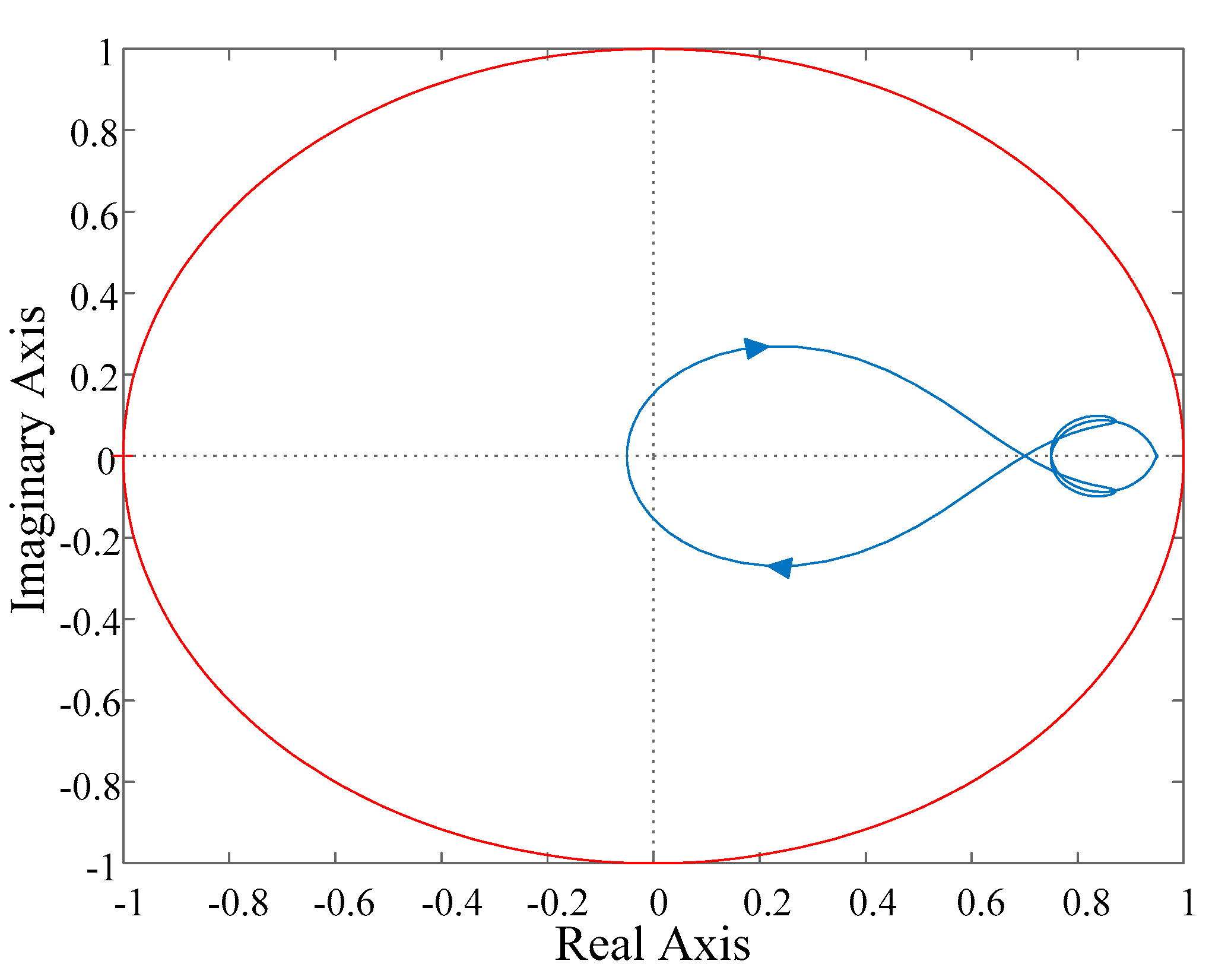
3.4. Stability of External Circuit: T(z)

T(z) is composed of external circuit transfer functions Gt(z) and GPI(z) of the hybrid repetitive controller as Equation (7). The locations of the poles of T(z) are determined by the external circuit transfer function from the active load, reactive inductance load, and capacitance load together with two proportional integral controllers. The larger the active load, the further inside the unit circle the poles of T(z) are located. The larger the capacitance load, the more unstable the system. Capacitors such as starting capacitors, capacitors for EMI, or power factor corrector capacitors are connected randomly and change dynamically. For a certain external circuit with Rload = 2.5 Ω and Lload = 15 mH, we can plot its pole diagram with the change of capacitance load to show its influence on system stability. As shown in Figure 11, when these capacitors are connected to the distribution network, the theoretical upper limit for stability is about 150 μF. The increase of capacitance load will result in poles moving out of the unit circle, accompanied by an intensification of harmonic amplification and gradual loss of system stability. The magnitudes of the poles of the transfer function T(z) are a stability criterion for the external circuit. If the magnitudes of all the poles are smaller than one, the external circuit is stable, otherwise it is unstable. The maximum values of moduli of poles with certain load capacitance (Cload = 150 μF), variable active load (represented by Rload), and variable inductive load (represented by Lload) are shown in Figure 12. These can validate the viewpoint on the effect of active load and inductance load on system stability.
Applying reactance to the external circuit of the positive feedback loop can suppress resonance well, appropriately increasing the reactance of the LCL filter. The design theory of the LCL filter is explained in [35,36,37,38]. Based on a reasonable design of the LCL filter, appropriately increasing the filter reactance can achieve good results in resonance suppression for capacitance loads.
We can also increase the stable margin of the system by optimizing the parameters of proportional integral controllers GPI1(z) and GPI2(z). It can be seen from the expression of T(z) that both proportional integral (PI) controllers affect the location of the poles. Generally, their integral coefficients need to be set to nearly zero. The stability can be improved by properly adjusting their proportional coefficients. Figure 13 shows the maximum values of moduli of poles from T(z) with different PI controller parameters. It can be found that a relatively small proportional coefficient can increase the stable margin of the system. Compared with changing the parameters of the LCL filter, setting the parameters of the PI controller is a better and simpler method.

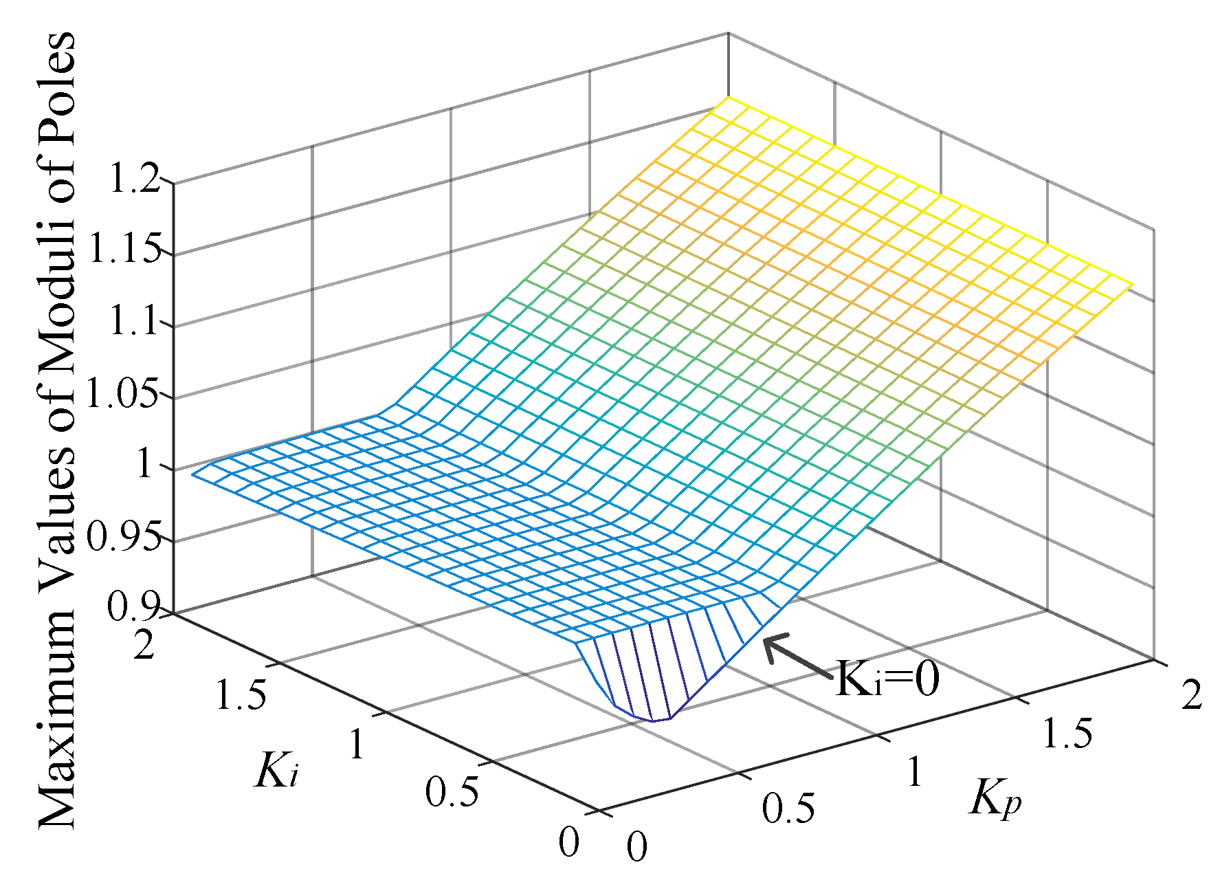
3.5. Stability of Hybrid Controller: H(z)

Transfer function H(z) is the criterion to measure whether the inverter of the shunt active power filter system can work in a stable state. The inverter stable criterion H(z) is composed of three transfer functions: P(z), Q(z), and S(z). P(z) is the plant transfer function of the external unit. After the stability function T(z) is stabilized by setting the PI parameters of GPI1(z) and GPI2(z), the plant transfer function P(z) is fixed. Q(z) and S(z) are designed to increase the stable margin of the system. From the perspective of the inverter stable criterion H(z), designing the repetitive controller is a process of modifying Q(z) and S(z) to increase the stability and robustness of the system under load variations.
A bode diagram of P(z) under the RL and RLC loads given in Table 1 is shown in Figure 14. The shunt APF system with 366.5 μF capacitance load has a resonant peak brought by the parallel resonant circuit and positive feedback loop. The resonant peak at low-intermediate frequency should be suppressed by modifying the repetitive controller. In [26,39], researchers pointed out that a especially designed Q(z) based on low–pass filter and leading link can increase the stable margin of the system. However, after the intermediate frequency gain of Q(z) decays, the modulus of H(z) will become larger due to the resonant peak of P(z). It is better to select Q(z) as an attenuation coefficient under this condition. Thus, we will focus on modifying the corrector unit S(z) in Section 4 to suppress the positive feedback of the capacitance load.

4. System Stabilization Strategies

The overall idea is to stabilize T(z) and H(z) by modifying the hybrid repetitive controller. Since the stability of the external circuit transfer function T(z) is only affected by the proportional integral controllers GPI1(z) and GPI2(z), first we can set the proportional coefficient of either PI to move the poles of T(z) into the unit circle. After that, the plant transfer function P(z) is fixed. The stability of H(z) is only affected by the hybrid repetitive controller. Then we can modify the corrector unit in the hybrid repetitive controller to make H(z) meet stability requirements. When both T(z) and H(z) are stable, the resonance will be suppressed and the system will be stable again.
The parameters of the digitally repetitive controlled shunt active power filter are shown in Table 1. It compensates for parallel RLC load. Poles of T(z) can be moved into the unit circle by selecting a relatively small proportional coefficient. Figure 15 shows this process by resetting Kp of GPI2 from 1 to 0.5. Attention should be paid in engineering to other links such as current transformer (CT), which may also introduce additional proportional coefficients to the control loop. These factors need to be considered when setting PI.
The repetitive controller realizes zero steady–state error tracking for periodic signals, and the parallel PI controller improves dynamic response speed when the load changes. System instability when compensating the μF capacitance load is a problem for APF steady-state control. Therefore, it is necessary to modify the repetitive controller. The corrector S(z) in the forward path of the repetitive controller has the functions of correcting amplitude compensation and phase compensation and improving the stable margin of the controller.
The inverter stable criterion transfer function can be defined as:
G p ( z ) = S ( z ) P ( z )
Transfer function Gp(z) reflects the stability state of the APF inverter under different load conditions. Therefore, the correction of the repetitive controller needs to be improved to suppress the resonant peak and ensure system stability. It also requires zero gain offset frequency response in a low-frequency band range. The corrector is composed of low–pass filter GLP(z), zero–phase shift notch filter Gn1(z), Gn2(z), and phase compensator zk, as shown by Equation (9):
S ( z ) = G L P ( z ) G n 1 ( z ) G n 2 ( z ) z k
Zero-phase shift notch filters are introduced to suppress the resonant peaks brought by the LCL filter and load capacitance. They do not degrade the steady–state performance of the repetitive controller. The zero-phase shift notch filter contains a leading element. If the notch frequency is low, it will be required to advance many beats, which will lead to instability. For the 366.5 μF capacitance load and LCL filter, the zero-phase shift notch filter is designed as Equations (10) and (11) respectively. A notch filter Gn1 of lower frequency is better for magnitude frequency correction but will result in instability.
G n 1 ( z ) = z 4 + 2 + z 4 4
G n 2 ( z ) = z 2 + 2 + z 2 4
The resonant peak brought by the load capacitance is eliminated by notch filter Gn1 and export PI unit GPI2. However, the capacitor follows the law of ic = cduc/dt. The harmonic voltage at PCC in a wide frequency range will be amplified to a large harmonic current by the capacitance load. Therefore, it is necessary to increase the compensation ability of the APF at low and medium frequencies by appropriately increasing the cut-off frequency of the low–pass filter of S(z). The second-order low–pass filter with a cut–off frequency of 1500 Hz and damping ratio of 0.707 is designed as follows:
G L P ( z ) = z 2 + 2 z + 1 12.2188 z 2 12.756 z + 4.5372
The phase compensation part zk does not affect the magnitude-frequency characteristics of Gp. We can find from Figure 16 that after the correction of S(z), the forward channel transfer function Gp no longer has a resonant peak.
Phase compensator zk is a leading part, compensating for the phase delay in each control unit. Figure 17 shows the phase frequency diagram of transfer function Gp under different values of k. Minimum phase displacement is attained when k = 6. Considering the one beat delay in digitally controlled implementation, k is chosen to be 7.
Q(z) is chosen as a close-to-unity constant 0.95 to ensure a larger stability margin and has high compensation accuracy. To verify the inverter stability criterion, a Nyquist diagram of H(z) with the modified hybrid controller is shown in Figure 18. The system satisfies the stability criterion. A Nyquist diagram of H(z) before modification is shown in Figure 10b. By comparing, the effect of the modified controller can be proved.
So far, we have finished the stabilization work of T(z) and H(z). The shunt APF system can run normally and stably with parallel RLC load (Cload = 366.5 μF).

5. Simulation and Experimental Results

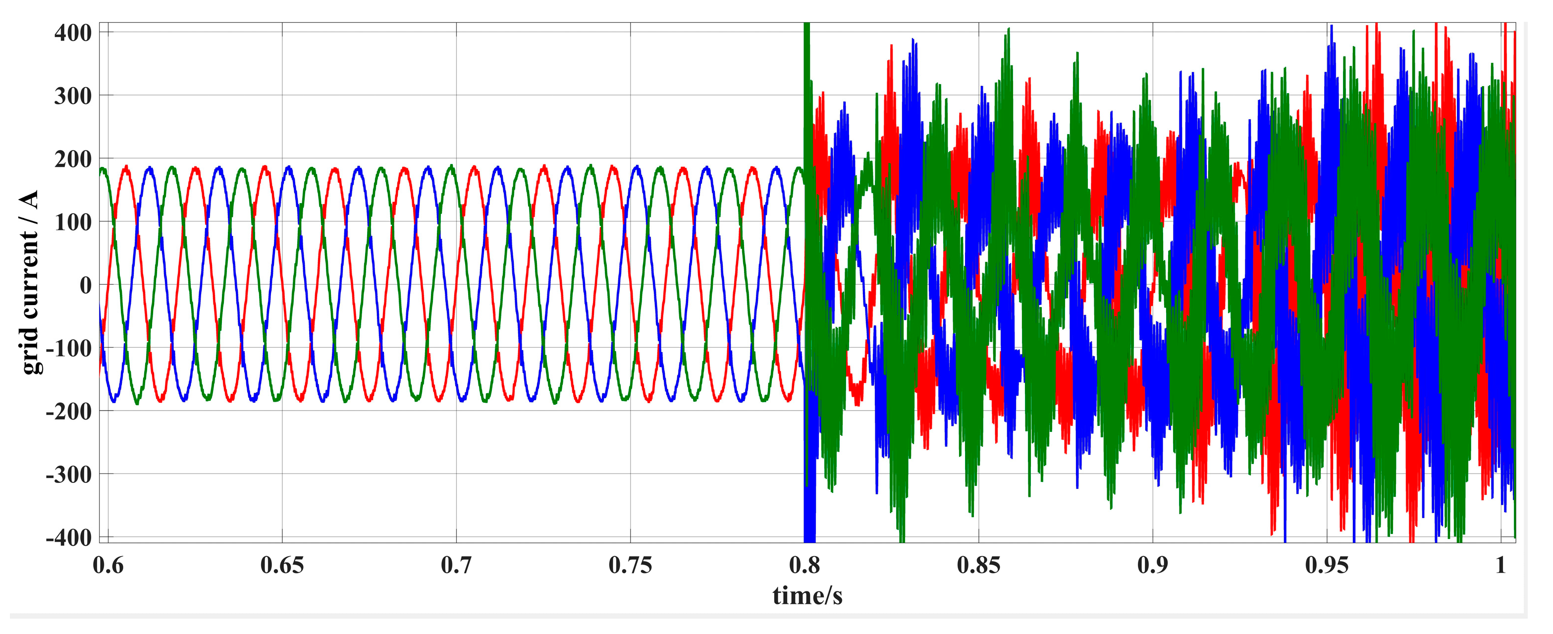
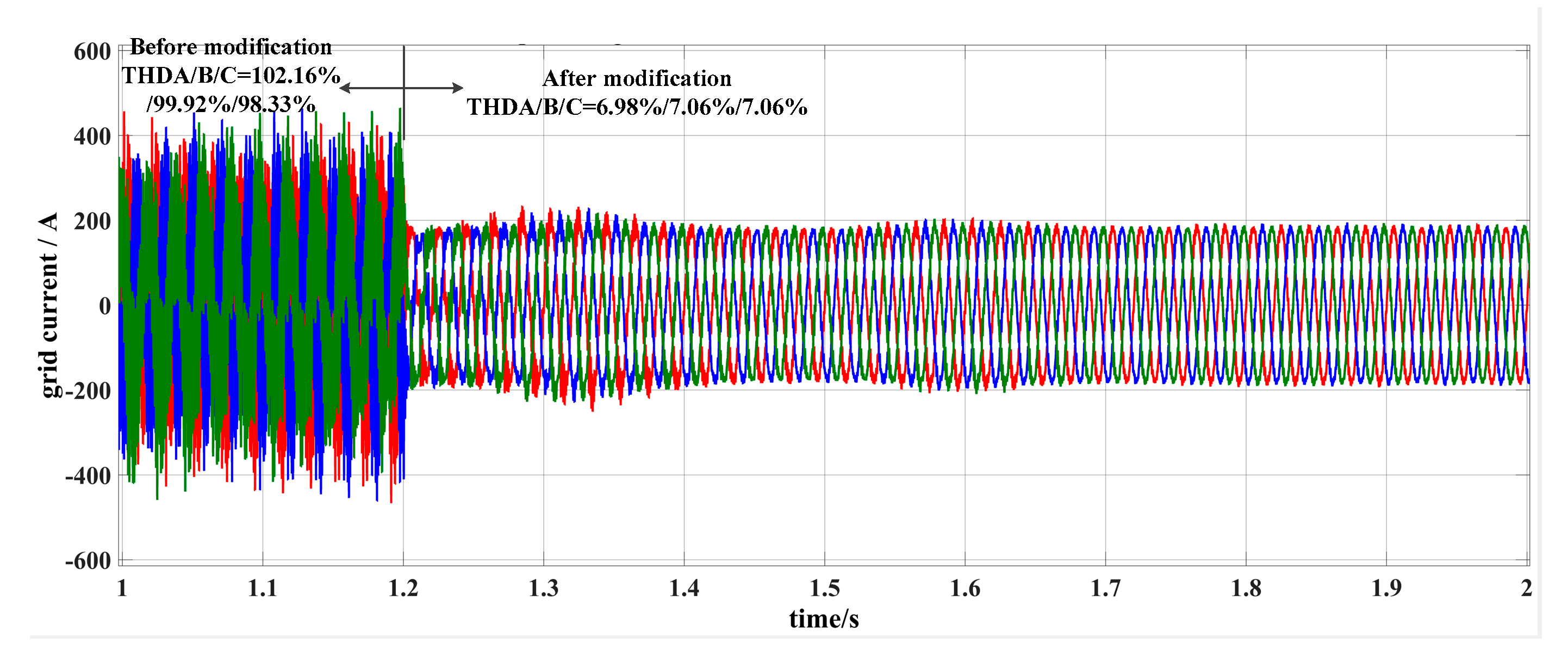
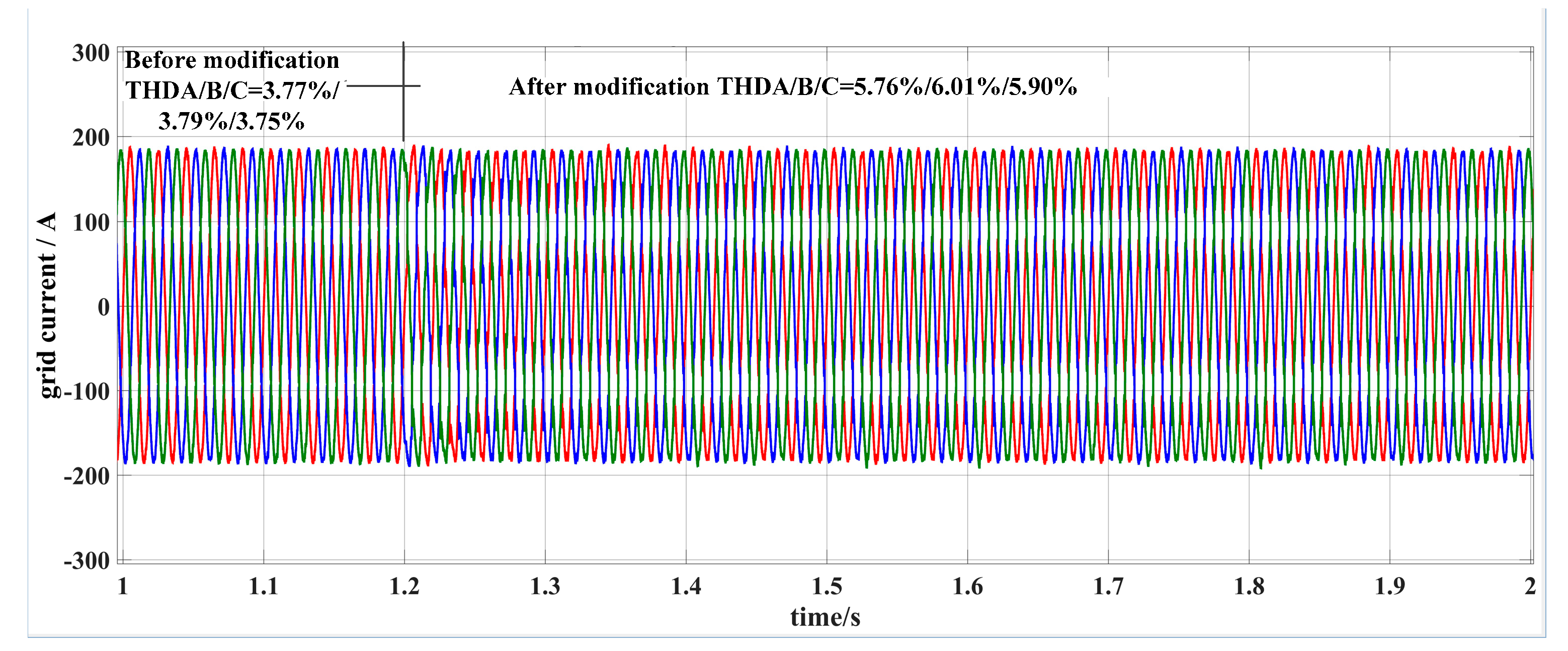
5.1. Simulation Results

We built an active power filter system on MATLAB/Simulink to verify the validity of the modified hybrid repetitive control strategy proposed above. The parameters of the digital repetitive controlled shunt active power filter are shown in Table 1, compensating for parallel RL or RLC load. A three-phase rectifier load represents load–side harmonics. Both load cases use a common repetitive control strategy before 1.2 s. After 1.2 s, the modified hybrid repetitive control strategy proposed above is used. We know from Figure 19 that when a parallel capacitance load is connected to a shunt APF with the common repetitive control strategy, harmonics are severely amplified and the system becomes unstable. When the modified hybrid repetitive control strategy is used, the whole system is stabilized and the active power filter can work well. Figure 20 shows our contrast experiment. It is used to illustrate that the proposed stabilization method is not applicable only to the specific case of load capacitance. The simulation results show that the shunt active power filter can perform well with RL load and rectifier load using the modified control strategy without sacrificing much compensation effect.

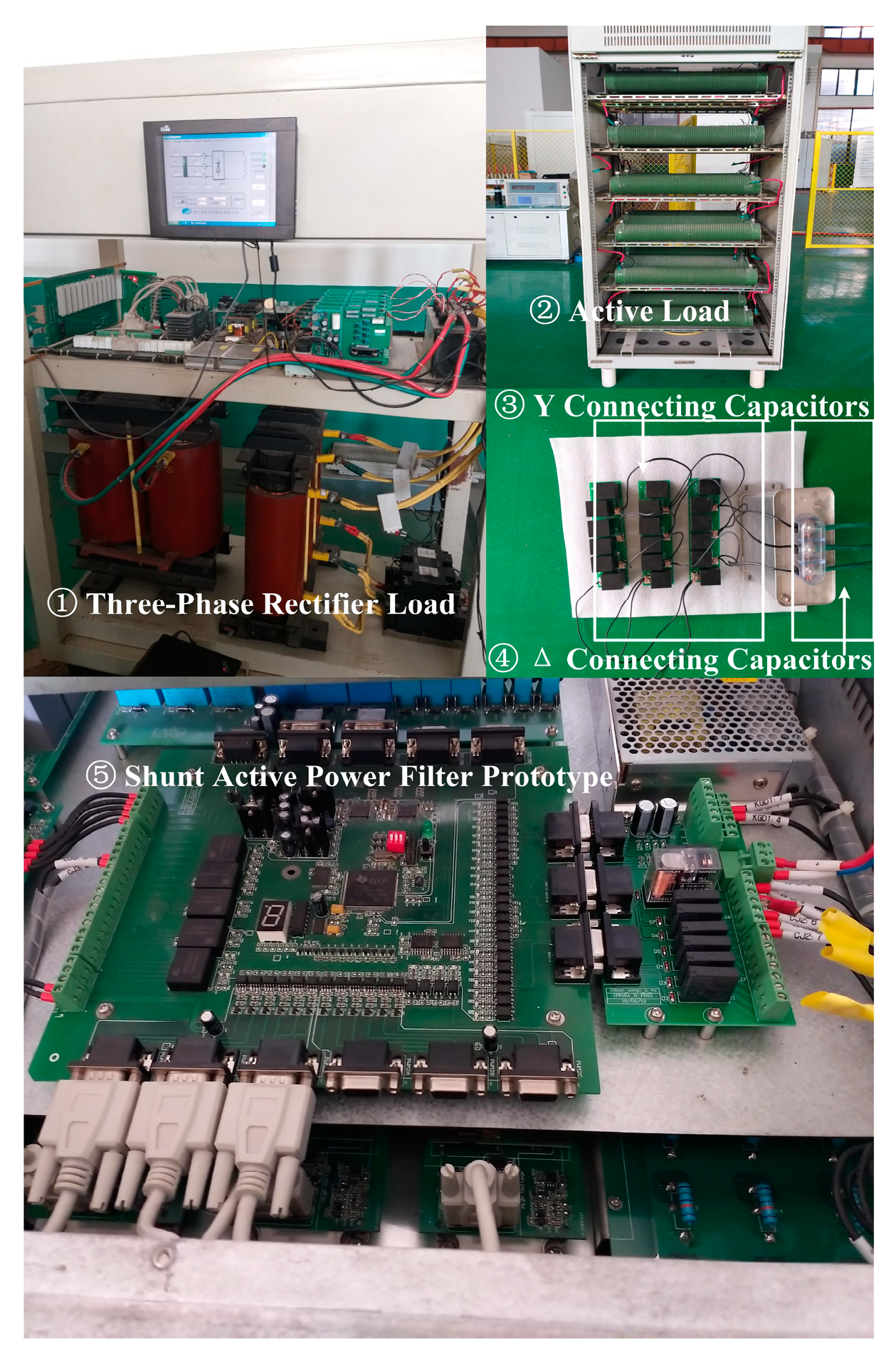
5.2. Experimental Results

A 75kVA shunt active power filter prototype was built on a TMS320F28335 digital signal processor (DSP), shown in Figure 21. A Fluke 435 power quality analyzer was used to capture the experimental results. The circuit parameters and controller were the same as those in Table 1, except that there was no inductance load in the prototype experiment. The GPI2 and low–pass filter of S(z) before and after modification are shown in Table 3.
Figure 22 shows the waveforms of the grid current and its harmonic spectra under active load and three-phase RL rectifier load before the APF is put into use. The grid current is seriously distorted, with total harmonic distortion (THD) up to 29.6%. After the shunt APF with common control strategy (before modification) is operated, harmonics are eliminated and the THD of the grid current reduces to 5.6%, as shown in Figure 23. However, when a parallel capacitance load is connected, harmonics are severely amplified and the THD of the grid current rises to 93.8%. Its waveforms and harmonic spectra are shown in Figure 24. Current flowing into the capacitance load under this condition is shown in Figure 25. The severely distorted capacitor current shows an amplification of the harmonics by the capacitive load. Moreover, the active power filter further amplifies the harmonics with a positive feedback loop.
The proposed modified control strategy in Section 5.1 can suppress the resonance well. There are electrical dampers such as line resistance in the external circuit of prototype experiment and practical engineering. Therefore, good system stabilization effect can be achieved without additional notch filters Gn1 and Gn2. We can suppress the resonance well only by modifying the exported proportional integral unit GPI2 and low–pass filter in the corrector unit S(z). The control method becomes simpler, clearer, and easier for parameter debugging. The waveforms of the grid current and its harmonic spectra with the modified control strategy under active load, three-phase rectifier load and parallel capacitors are shown in Figure 26. The THD value is reduced from 93.8% to 10.8%. When the experiment is repeated with the modified control strategy under active load, three-phase rectifier load, and parallel capacitors the THD only increases from 5.6% to 6.4%. The grid current waveforms for the repeat experiment are shown in Figure 27. Compared with the common control strategy and its waveforms in Figure 20, the proposed improved hybrid repetitive control strategy can suppress the resonance brought by capacitance load without sacrificing much compensation effect of the common RL and rectifier load.

6. Conclusions

In this paper, system instability and resonance resulting from the interactions between the shunt active power filter and the capacitance load were discussed. Few papers have noticed this phenomenon, and it cannot be reflected by the existing conventional APF model. For this study, we identified the drawbacks of the conventional model and proposed a more precise modified model. Compared with the conventional mode, it had the following advantages:
  • The dynamic characteristics of input signals of active power filter were taken into account.
  • The external circuit (power grids and the loads) were modelled.
  • The stability problem of the system could be reflected more accurately.
By means of the modified model, we could show the positive feedback resonance stability problem and study its mechanism. We decomposed the complex sensitive function into several parts and studied the effect of each link on system stability separately. Furthermore, according to the relationships between the parts of the hybrid controller, we stabilized the system. The whole design process was given in detail. The correctness and validity of the proposed strategy were verified by simulation analysis and prototype experiments, proving the existence of the problem and the effectiveness of the solution. The proposed stabilization method is simple, clear, and easy for parameter debugging. In the future, researchers can apply more strategies to increase the ability of shunt APFs to carry parallel capacitance loads or improve the performance of harmonic suppression and system stabilization under this condition. In this paper, the system under the repetitive controller was analyzed in detail. The stability problems and resonance existed not only in the repetitive controller studied here, but also in the proportional resonance controller in [22]. In the future, researchers can analyze the stability problems of active power filters with other controllers.

Author Contributions

Y.B.: Methodology, formal analysis, investigation, and validation; D.J.: Methodology, project administration, and resources; Y.L.: Methodology, project administration, and resources; C.J.: Validation and data curation; T.H.: Validation and data curation; L.Y.: Validation and data curation; P.H.: Validation and data curation.

Funding

This research received no external funding.

Conflicts of Interest

The authors declare no conflict of interest.

References

  1. Wang, L.; Lam, C.; Wong, M. Hybrid structure of static var compensator and hybrid active power filter (SVC//HAPF) for medium-voltage heavy loads compensation. IEEE Trans. Ind. Electron. 2018, 65, 4432–4442. [Google Scholar] [CrossRef]
  2. Sasaki, H.; Machida, T. A new method to eliminate AC harmonic current by magnetic compensation consideration on basic design. IEEE Trans. Power Appar. Syst. 1971, 90, 2009–2019. [Google Scholar] [CrossRef]
  3. Tareen, W.; Mekhielf, S. Three-phase transformerless shunt active power filter with reduced switch count for harmonic compensation in grid-connected applications. IEEE Trans. Power Electron. 2018, 33, 4868–4881. [Google Scholar] [CrossRef]
  4. Wang, Y.; Wang, Y.; Chen, S.; Zhang, Z.; Zhang, Y. A simplified minimum DC-link voltage control strategy for shunt active power filters. Energies 2018, 11, 2407. [Google Scholar] [CrossRef]
  5. Bosch, S.; Staiger, J.; Steinhart, H. Predictive current control for an active power filter with LCL-filter. IEEE Trans. Ind. Electron. 2018, 65, 4943–4952. [Google Scholar] [CrossRef]
  6. Wang, L.; Lam, C.; Wong, M. Unbalanced control strategy for a thyristor-controlled LC-coupling hybrid active power filter in three-phase three-wire systems. IEEE Trans. Power Electron. 2017, 32, 1056–1069. [Google Scholar] [CrossRef]
  7. Li, S.; Liang, X.; Fei, J. Dynamic surface adaptive fuzzy control of three-phase active power filter. IEEE Access. 2016, 4, 9451–9458. [Google Scholar] [CrossRef]
  8. Fei, J.; Chu, Y.; Hou, S. A backstepping neural global sliding mode control using fuzzy approximator for three-phase active power filter. IEEE Access. 2017, 5, 16021–16032. [Google Scholar] [CrossRef]
  9. Liu, N.; Fei, J. Adaptive fractional sliding mode control of active power filter based on dual RBF neural networks. IEEE Access. 2017, 5, 27590–27598. [Google Scholar] [CrossRef]
  10. Hou, S.; Fei, J.; Chu, Y.; Chen, C. Experimental investigation of adaptive fuzzy global sliding mode control of single-phase shunt active power filters. IEEE Access. 2019, 7, 64442–64449. [Google Scholar] [CrossRef]
  11. Zeng, Z.; Yang, J.; Chen, S.; Huang, J. Fast-transient repetitive control strategy for a three-phase LCL filter-based shunt active power filter. J. Power Electron. 2014, 14, 392–401. [Google Scholar] [CrossRef]
  12. Fang, Z. Application issues and characteristics of active power filters. IEEE Ind. Appl. Mag. 1998, 4, 21–30. [Google Scholar] [CrossRef]
  13. Fang, Z. Harmonic sources and filtering approaches. IEEE Ind. Appl. Mag. 2001, 7, 18–25. [Google Scholar]
  14. Ceaki, O.; Vatu, R.; Golovanov, N.; Porumb, R.; Seritan, G. Analysis of SVC influence on the power quality for grid-connected PV plants. In Proceedings of the 2014 International Symposium on Fundamentals of Electrical Engineering (ISFEE), Bucharest, Romania, 28–29 November 2014. [Google Scholar]
  15. Ceaki, O.; Vatu, R.; Mancasi, M.; Porumb, R.; Seritan, G. Analysis of electromagnetic disturbances with or without SVC device. In Proceedings of the 2015 50th International Universities Power Engineering Conference (UPEC), Stoke on Trent, UK, 1–4 September 2015. [Google Scholar]
  16. Francis, B.; Wonham, W. The internal model principle of control theory. Automatica 1976, 12, 457–465. [Google Scholar] [CrossRef]
  17. Grino, R.; Castello, R.; Fossas, E. Digital control of a single-phase shunt active power filter. In Proceedings of the IEEE 34th Annual Conference on Power Electronics Specialist, Acapulco, Mexico, 15–19 June 2003; pp. 1038–1042. [Google Scholar]
  18. Zimann, F.; Neto, R.; Neves, F.; Souza, H.E.P.; Batschauer, A.L.; Rech, C. A complex repetitive controller based on the generalized delayed signal cancelation method. IEEE Trans. Ind. Electron. 2019, 66, 2857–2867. [Google Scholar] [CrossRef]
  19. Fang, J.; Xiao, G.; Yang, X.; Tang, Y. Parameter design of a novel series-parallel-resonant LCL filter for single-phase half-bridge active power filters. IEEE Trans. Power Electron. 2017, 32, 200–217. [Google Scholar] [CrossRef]
  20. Xie, C.; Zhao, X.; Savaghebi, M.; Meng, L.; Meng, L.; Guerrero, J.M.; Vasquez, G.C. Multirate fractional-order repetitive control of shunt active power filter suitable for microgrid applications. IEEE J. Emerg. Sel. Topics Power Electron. 2017, 5, 809–819. [Google Scholar] [CrossRef]
  21. Zou, Z.; Zhou, K.; Wang, Z.; Cheng, M. Frequency-adaptive fractional-order repetitive control of shunt active power filters. IEEE Trans. Ind. Electron. 2015, 62, 1659–1668. [Google Scholar] [CrossRef]
  22. Grino, R.; Cardoner, R.; Castello, R.; Fossas, E. Digital repetitive control of a three-phase four-wire shunt active filter. IEEE Trans. Ind. Electron. 2007, 54, 1495–1503. [Google Scholar] [CrossRef]
  23. Castello, R.; Grino, R.; Fossas, E. Odd-harmonic digital repetitive control of a single-phase current active filter. IEEE Trans. Power Electron. 2004, 19, 1060–1068. [Google Scholar] [CrossRef]
  24. Yang, L.; Yang, J. A robust dual-loop current control method with a delay-compensation control link for LCL-type shunt active power filters. IEEE Trans. Power Electron. 2018, 34, 6183–6199. [Google Scholar] [CrossRef]
  25. Grino, R.; Castello, R. Digital repetitive plug-in controller for odd-harmonic periodic references and disturbances. Automatica 2005, 41, 153–157. [Google Scholar] [CrossRef]
  26. Jiang, S.; Cao, D.; Peng, F.Z.; Li, Y.; Liu, J. Low-THD, fast-transient, and cost-effective synchronous-frame repetitive controller for three-phase UPS inverters. IEEE Trans. Power Electron. 2012, 27, 2994–3005. [Google Scholar] [CrossRef]
  27. Cerrada, A.; Ardila, O.; Batlle, V.; Roncero-Sanchez, P.; Garcia-Gonzalez, P. Application of a repetitive controller for a three-phase active power filter. IEEE Trans. Power Electron. 2007, 22, 237–246. [Google Scholar] [CrossRef]
  28. Sun, J.; Gong, J.; Chen, B.; Zha, X. Analysis and design of repetitive controller based on regeneration spectrum and sensitivity function in active power filter system. IET Power Electron. 2014, 7, 2133–2140. [Google Scholar] [CrossRef]
  29. Tanaka, T.; Akagi, H. A new method of harmonic power detection based on the instantaneous active power in three-phase circuits. IEEE Trans. Power Del. 1995, 10, 1737–1742. [Google Scholar] [CrossRef]
  30. Peng, F.; Ott, W.; Adams, D. Harmonic and reactive power compensation based on the generalized instantaneous reactive power theory for three-phase four-wire systems. IEEE Trans. Power Electron. 1998, 13, 1174–1181. [Google Scholar] [CrossRef]
  31. Soares, V.; Verdelho, P.; Marques, G. An instantaneous active power and reactive current component method for active filters. IEEE Trans. Power Electron. 2000, 15, 660–669. [Google Scholar] [CrossRef]
  32. Lascu, C.; Asiminoaei, C.; Boldea, I.; Blaabjerg, F. High performance current controller for selective harmonic compensation in active power filters. IEEE Trans. Power Electrons. 2007, 22, 1826–1835. [Google Scholar] [CrossRef]
  33. Girgis, A.; Chang, W.; Makram, E. A digital recursive measurement scheme for on-line tracking of power system harmonics. IEEE Trans. Power Del. 1991, 6, 1153–1160. [Google Scholar] [CrossRef]
  34. Li, H.; Zhuo, F.; Wang, Z.; Lei, W.; Wu, L. A novel time-domain current-detection algorithm for shunt active power filters. IEEE Trans. Power Syst. 2005, 20, 644–651. [Google Scholar] [CrossRef]
  35. Kouchaki, A.; Nymand, M. Analytical design of passive LCL filter for three-phase two-level power factor correction rectifiers. IEEE Trans. Power Electron. 2018, 33, 3012–3022. [Google Scholar] [CrossRef]
  36. Jayalath, S.; Hanif, M. Generalized LCL-filter design algorithm for grid-connected voltage-source inverter. IEEE Trans. Ind. Electron. 2017, 64, 1905–1915. [Google Scholar] [CrossRef]
  37. Jiao, Y.; Lee, F. LCL filter design and inductor current ripple analysis for a three-level NPC grid interface converter. IEEE Trans. Power Electron. 2015, 30, 4659–4668. [Google Scholar] [CrossRef]
  38. Liu, Q.; Peng, L.; Kang, Y.; Tang, S.; Wu, D.; Qi, Y. A novel design and optimization method of an LCL filter for a shunt active power filter. IEEE Trans. Ind. Electron. 2014, 61, 4000–4010. [Google Scholar] [CrossRef]
  39. Zhang, B.; Zhou, K.; Wang, D. Multirate repetitive control for PWM DC/AC converters. IEEE Trans. Ind. Electron. 2014, 61, 2883–2890. [Google Scholar] [CrossRef]
Figure 1. Structure and control scheme of a three-phase four-wire shunt active power filter system.
Energies 12 02084 g001
Figure 2. Scheme of hybrid repetitive controller.
Energies 12 02084 g002
Figure 3. Conventional model of a hybrid repetitive controlled shunt active power filter.
Energies 12 02084 g003
Figure 4. Nyquist diagram of H(z) for shunt APF system.
Energies 12 02084 g004
Figure 5. Simulated waveform of grid current under different conditions (parameters from Table 1).
Energies 12 02084 g005
Figure 6. Simulated waveform of grid current under different conditions (repeated simulation of [22]).
Energies 12 02084 g006
Figure 7. Modified model of shunt active power filter system.
Energies 12 02084 g007
Figure 8. External circuit of shunt active power filter system.
Energies 12 02084 g008
Figure 9. Sufficient stability criterion under resistor-inductor (RL) load. (a) Pole diagram of T(z) under RL load. (b) Nyquist diagram of H(z) under RL load.
Energies 12 02084 g009
Figure 10. Sufficient stability criterion under resistor-inductor-capacitor (RLC) load. (a) Pole diagram of T(z) under RLC load. (b) Nyquist diagram of H(z) under RLC load.
Energies 12 02084 g010
Figure 11. Poles of T(z) with change of capacitance load.
Energies 12 02084 g011
Figure 12. Maximum values of moduli of poles of T(z) with certain Cload and variable RL load.
Energies 12 02084 g012
Figure 13. Maximum values of moduli of poles of T(z) with different GPI2(z) controller parameters.
Energies 12 02084 g013
Figure 14. Bode diagram of P(z) under different load conditions.
Energies 12 02084 g014
Figure 15. Setting Kp of GPI2 to move poles of T(z) into the unit circle.
Energies 12 02084 g015
Figure 16. Magnitude-frequency diagram of S(z)P(z) when controller is before or after modification.
Energies 12 02084 g016
Figure 17. Phase correction effect of zk to S(z)P(z).
Energies 12 02084 g017
Figure 18. Nyquist diagram of stability criterion H(z) of modified hybrid controller with capacitance load.
Energies 12 02084 g018
Figure 19. Simulated grid current isys when shunt APF is compensating for RLC load and rectifier load.
Energies 12 02084 g019
Figure 20. Simulated grid current isys when shunt APF is compensating for RL load and rectifier load.
Energies 12 02084 g020
Figure 21. Experimental 75 kVA shunt active power filter prototype.
Energies 12 02084 g021
Figure 22. Waveforms of grid current and its harmonic spectra carrying active load and three-phase rectifier load without shunt APF prototype.
Energies 12 02084 g022
Figure 23. Waveforms of grid current and its harmonic spectra with common control strategy shunt APF prototype carrying active load and three-phase rectifier loads.
Energies 12 02084 g023
Figure 24. Waveforms of grid current and its harmonic spectra with common control strategy shunt APF prototype after parallel capacitance load is connected at the point of common coupling (PCC).
Energies 12 02084 g024
Figure 25. Waveforms of capacitor current.
Energies 12 02084 g025
Figure 26. Waveforms of grid current and its harmonic spectra with modified strategy control shunt APF prototype after parallel capacitance load is connected at PCC.
Energies 12 02084 g026
Figure 27. Waveforms of grid current and its harmonic spectra with modified strategy control shunt APF prototype carrying active load and three-phase rectifier load.
Energies 12 02084 g027
Table 1. Parameters of shunt active power filter.
Circuit ParametersController Part
SymbolParameter Physical MeaningsControl UnitIllustration
Usys220 VSystem phase voltage (RMS)N = 256fs/f0
Lvs50 μHSystem reactanceQ(z) = 0.95Attenuation coefficient
Udc700 VDC bus voltage of APFGPI1(z) = 1Proportion unit
f050 HzFrequency of distribution networkGPI2(z) = 1Proportion unit
fs12.8 kHzSample frequencyS(z)Corrector
Lf0.375 mHInductance of inverter side of LCL
Lg0.075 mHInductance of grid side of LCL
Cf30 μFCapacitor of LCL
Rload4.4 ΩParallel active load
Lload15 mHParallel inductance load
Cload(Y)90 μFY connecting parallel capacitance load
Cload(Δ)276.5 μFΔ connecting parallel capacitance load
3 ph rectifier loadRepresents harmonics
Rline0.05 ΩRepresents line resistance
Usys220 VSystem phase voltage (RMS)
Table 2. Flaws of the conventional model of a shunt APF.
Dynamic characteristics of input signals are ignored
External circuits (power grids and loads) are ignored
Some stability problems cannot be reflected
Table 3. Control units of shunt APF system.
Before Modification
Control unitValues
GPI2(z)Kp = 1; Ki = 0.0001
GLP(z) 2nd Butterworth low-pass filterCut–off frequency = 500 Hz
After Modification
GPI2(z)Kp = 0.5; Ki = 0.0001
GLP(z) 2nd Butterworth low-pass filterCut–off frequency = 1000 Hz

