Article

Development of Hardware-in-the-Loop-Simulation Testbed for Pitch Control System Performance Test

1
Korea Electrotechnology Research Institute (KERI), 12, Bulmosan-ro 10, Seongsan-gu, Changwon-si 51543, Korea
2
Department of Electrical Engineering, Pusan National University, Busan 46241, Korea
*
Author to whom correspondence should be addressed.
Energies 2019, 12(10), 2031; https://doi.org/10.3390/en12102031
Submission received: 22 April 2019 / Revised: 22 May 2019 / Accepted: 23 May 2019 / Published: 27 May 2019
(This article belongs to the Special Issue Design, Fabrication and Performance of Wind Turbines 2019)

Abstract

:
This paper deals with the development of a wind turbine pitch control system and the construction of a Hardware-in-the-Loop-Simulation (HILS) testbed for the performance test of the pitch control system. When the wind speed exceeds the rated wind speed, the wind turbine pitch controller adjusts the blade pitch angles collectively to ensure that the rotor speed maintains the rated rotor speed. The pitch controller with the individual pitch control function can add individual pitch angles into the collective pitch angles to reduce the mechanical load applied to the blade periodically due to wind shear. Large wind turbines often experience mechanical loads caused by wind shear phenomena. To verify the performance of the pitch control system before applying it to an actual wind turbine, the pitch control system is tested on the HILS testbed, which acts like an actual wind turbine system. The testbed for evaluating the developed pitch control system consists of the pitch control system, a real-time unit for simulating the wind and the operations of the wind turbine, an operational computer with a human–machine interface, a load system for simulating the actual wind load applied to each blade, and a real pitch bearing. Through the several tests based on HILS test bed, how well the pitch controller performed the given roles for each area in the entire wind speed area from cut-in to cut-out wind speed can be shown.

1. Introduction

A wind turbine is operated in various modes depending on the wind speed as shown in Figure 1 [1]. The wind turbine starts to generate electricity above the cut-in wind speed. In the region below the rated wind speed, generator torque control of the wind turbine is performed while keeping the pitch angle to a minimum (i.e., 0 degrees) to achieve the maximum efficiency of power generation. When the wind speed exceeds the rated wind speed, pitch control is performed by adjusting the blade pitch angles that limit the amount of captured power by regulating the rotational speed of the rotor at the rated rotational speed and generator control is performed to keep the generator’s rated torque such that the generated power maintains its rated value [2]. When the wind speed is above the cut-out speed, pitch control alters the pitch angles maximally to stop the wind turbine. To successfully perform pitch control according to each control mode, the roles of the turbine controller that generates a command distinguishing control modes by monitoring the wind condition and the pitch controller that controls the pitch angles are important [3].
Pitch control has two objectives in the region above the rated wind speed. The first objective is to keep the rotational speed of the rotor at the rated rotational speed so that the wind turbine maintains its rated output [4]. For this purpose, if the rotor speed is above the rated rotor speed, pitch control is activated to decrease the rotor speed by increasing the pitch angles, thereby reducing the power coefficient ( C p ), or if the rotor speed is below the rated rotor speed, pitch control is activated to increase the rotor speed by decreasing the pitch angles, thereby increasing C p [5]. The second objective is to reduce the mechanical fatigue loads on the blade by the wind. Large wind turbines often experience wind shear, a sudden change of the wind direction or intensity [6]. In this case, a load occurs at 1P cycle, which is one rotation component of the rotational speed of the blade. Such load accumulation adversely affects the lifetime of the wind turbine [7]. To reduce the periodic fatigue load, the pitch angle of each blade is individually controlled according to the altitude of each blade [8].
The best way to develop a pitch control system, including the pitch control algorithm, is to apply it to an actual wind turbine. However, arbitrarily changing the wind speed blowing to a wind turbine is practically impossible. Moreover, applying the pitch control system to a real wind turbine is costly and time-consuming [9]. As an alternative, a Hardware-In-the-Loop Simulation (HILS) testbed is suggested. A HILS testbed is based on a real-time simulator that is responsible for a real wind turbine [10].
The model of the wind turbine is implemented using FAST (Fatigue, Aerodynamics, Structures, and Turbulence) aeroelastic computer-aided engineering tool developed by the National Renewable Energy Laboratory (NREL) [11]. The ideal environment for controller performance testing is to apply to actual targets, but for costly and time-consuming larger systems such as wind turbines, real-time simulators based on numerical modeling are used, in general. Since the purpose of this paper is to develop the pitch controller and to test the performance, for pitch systems that are directly controlled by pitch controllers, real pitch systems that can actually be installed on wind turbines instead of using numerical modeling [12] are built and used. Therefore, reliability of the performance evaluation results of pitch controller can be increased.
This paper is composed as follows. In Section 2, the development of the pitch control system is introduced. In Section 3, the configuration of the HILS testbed based on the real-time simulator is described. In Section 4, the test results for the performance verification of the developed pitch control system are explained, and this paper concludes in Section 5.

2. Design of the Pitch System

This section introduces the development of the pitch system by explaining the configuration of the system and its components.

2.1. Configuration of the Pitch System

As shown in Figure 2, the developed pitch system consists of a main box and a pitch drive system for each blade. The main box consists of a pitch control unit (PCU), power distribution circuit, power protection circuit, and signal protection circuit. The pitch drive system consists of a pitch motor and an axis box, including a pitch drive unit (PDU) to drive a pitch motor and other electrical components (i.e., circuit breakers, magnetic contactors, inductors, relays, etc.). The PDU consists of a rectifier, an initial charge current limit circuit, a DC-link smoothing circuit, a chopper circuit for a pitch motor brake power supply, a dynamic braking device, a digital signal processor (DSP) control board, and an inverter for driving the pitch motor.
The PCU is responsible for the pitch system control. It receives control commands from a turbine control unit (TCU) through a CANopen communication protocol and conveys the commands to the pitch system. It also transmits both its own and the PDU’s status information to the TCU.
The system includes the two following pitch control modes: the collective pitch control (CPC) mode in which the pitch system adjusts the pitch angles of three blades simultaneously to regulate the output power to the rated power, and the individual pitch control (IPC) mode in which the system alters the pitch angles separately to reduce the mechanical fatigue applied to the blade.
In CPC mode, the PCU sends the pitch angle command obtained from the TCU to the three PDUs as the same value. In IPC mode, the PCU executes an IPC algorithm to calculate an additional IPC of each blade. To do this, the PCU needs the azimuth angle of the rotor and the out-of-plane bending moment value of each blade, which is obtained from sensors installed at the hub of the wind turbine. In this paper, the azimuth angle of the rotor and the out-of-plane bending moment values are obtained from the wind turbine model developed by the NREL.

2.2. Pitch Control Unit

2.2.1. Overview

Figure 3 shows the operation flowchart of the TCU and PCU. According to the TCU flowchart in Figure 3, pitch control is performed in the following three modes according to the TCU operation: starting mode, normal operation mode, and shutdown mode [13]. In these modes, the TCU generates pitch control commands such as target pitch angle, target pitch speed, and target pitch acceleration. The PCU follows the commands from the TCU when the PCU is in normal or emergency mode.

2.2.2. Control Algorithm

When the TCU is powered on, it initializes and goes into checking mode in which it checks its own status. The PCU also goes through the same process. Meanwhile, the TCU waits until it receives a signal that the PCU is in stop mode. Stop mode means that the pitch motor can operate but is being stopped. The PCU sends its stop mode state to the PCU. After receiving the information, the TCU goes into standstill mode, in which the wind turbine determines whether the wind turbine can be started.
The TCU checks the wind speed, and if the wind speed is between the cut-in wind speed and the cut-out wind speed for a certain period of time, then the TCU moves to waiting mode and sends a signal to the PCU to go into normal mode. After receiving acknowledgement that the PCU is in normal mode, the TCU in waiting mode sends commands to the PCU to decrease the pitch angles gradually from the feathering position (i.e., about 90 degrees) to the fine position enough to rotate the blades.
When the rotational speed of the generator reaches the minimum level to start the wind turbine, the TCU goes into starting mode. In starting mode, the TCU reduces the pitch angles to 0 degrees so that C p of the wind turbine can be maximized. The maximum C p makes the generator rotational speed increase, and if the minimum generator rotational speed to generate power is achieved, the TCU goes into normal operation mode.
When the TCU is in normal operation mode below the rated wind speed, the TCU controls the PCU to keep the pitch angles at the minimum so that the maximum C p can be obtained. In normal operation mode, the TCU also calculates the generator torque command value to generate power at maximum efficiency and enables the maximum power point tracking (MPPT) operation.
Above the rated wind speed, the generated power of the wind turbine must be limited to the rated power. For this purpose, the TCU maintains the generator torque and the rotor rotational speed at their respective rated values. To do this, the TCU transmits the rated torque value to the torque controller and calculates the pitch angles for maintaining the rated rotor rotational speed and transfers them to the PCU. To generate pitch angles to maintain the rated rotational speed, the TCU uses a controller to reduce the error between the rated rotational speed and the feedback rotor rotational speed [14]. The TCU transmits the pitch angle outputs generated by the controller to the PCU so that the PCU performs pitch control for the rotor speed. The principle of adjusting the rotor speed through pitch angle is as follows.
If the rotor rotational speed is faster than the rated value, the C p must be decreased by increasing the pitch angles, thereby decelerating the rotor. If the rotor rotational speed is slower than the rated value, the C p must be increased by decreasing the pitch angles, thereby accelerating the rotor.
The pitch control which maintains the rotor rotational speed at the rated wind speed is called the CPC, and in CPC mode, the pitch angles of three blades are all the same.
The effect of reducing the load on the blade can also be obtained through pitch control which is operated above the rated wind speed. For large wind turbines, cyclic load may occur on the blade due to wind shear phenomena with different wind speeds depending on the position of the blade. In this situation, adjusting the pitch angle of each blade to reduce the influence of wind on each blade position can reduce cyclic load due to wind shear. The pitch control for reducing blade loads is implemented in the PCU where a pitch controller receives the azimuth angle and the load value such as the root bending moment of each blade and produce pitch angles to minimize the blade loads.
Above the rated wind speed, pitch control should be performed to reduce the blade loads while maintaining the rated rotor rotational speed. For this purpose, the PCU generates the final pitch control angles by adding the CPC pitch angles to the pitch angles for blade load reduction from its own pitch controller. This control mode is called IPC because the pitch angle of each blade finally is created individually.
If the TCU is in normal operating mode but the wind turbine cannot generate power any longer, the TCU goes into shutdown mode to stop the wind turbine. Shutdown mode is divided into normal shutdown mode and emergency shutdown mode. In normal shutdown mode, if the wind speed is not between the cut-in wind speed and the cut-out wind speed, the TCU sends a signal to the PCU to move the pitch angles into the feathering position. Due to the pitch angles’ feathering position, aerodynamic braking occurs, and the wind turbine stops operation. When the TCU detects an abnormal problem of the wind turbine system, the TCU goes into emergency shutdown mode. In this mode, the blades change their pitch angles to the feathering position as quickly as possible to stop the wind turbine’s operation to ensure the safety-run operation. When normal shutdown has been completed or the emergency condition is cleared, the PCU returns to standstill mode and informs the TCU of its mode. Then, the TCU performs the previous procedure again.
Figure 4 shows a state machine of the PCU. The PCU receives commands from the TCU and the health information of the pitch drive system from the PDU to determine whether the PCU is in a state transition condition. The PCU sends control commands related to the pitch operation to the PDU in normal or emergency mode.
When the PDU has completed its initialization and is ready to operate, it sends a “PDU operation enabled” signal to the PCU, and the state of the PCU then transitions from state 1 to state 2, i.e., when the PDU is initialized with the PCU initialized, the state of PCU is turned into the state 2 where control and monitoring operations can be started. If the PCU receives the temperature information of components such as a pitch motor, an axis box, an inverter, and a backup power from each PDU, and if the temperatures are within normal ranges, then the PCU transitions from state 2 to state 3. If the abnormal temperature values appear during continuous monitoring, the PCU returns to state 2 even if it is in state 3.
The PCU receives the charge voltage of the backup power source from each PDU and checks it. If the charge voltage level is within the normal range, the PCU transitions from state 3 to state 4. In normal mode, the PCU sends commands to the PDU to release the motor brake and operate the pitch motor. The PCU transmits the target CPC angles calculated by the TCU or the target IPC angles calculated by the PCU to the PDU; the PCU also transmits the pitch motor speed and the pitch motor acceleration/deceleration commands to the PDU. The PDU transfers the motor current, the backup power supply voltage, and the pitch position value measured by a pitch resolver and a pitch gear encoder to the PCU. When the PCU is in state 4 and receives a notification that the normal condition has been cleared from the TCU, the PCU returns to state 3.
If the wind turbine is stopped due to an error, the PCU informs the PDU that the situation is an emergency, and the PDU controls the pitch angles to the feathering position at the maximum speed. When the blades are in the feathering position and the limit switch of the pitch gear is turned on, the PDU sends a “safety-run operation complete” signal to the PCU. If an abnormal condition is detected in the normal mode of state 3, the PCU immediately goes into the emergency mode of state 5. If the condition is resolved in state 5, the state of PCU is transfered to state 3. When the PCU receives the commands related to pitch control from the TCU in the region above the rated wind speed, the PCU transfers the commands to the PDU so that the pitch system operates in CPC or IPC mode.
Figure 5 shows the blade rotating coordinate system with the parameters required for implementation of the individual pitch controller [15]. In the notation of the axis moment M b , { x , y , z } i , b denotes the blade rotating coordinate system with { x , y , z } being the axis and i for i = 1 , 2 , 3 being the blade number. For example, M b y i represents the y-axis moment of the ith-blade rotating coordinate system. As shown in Figure 5, M b y i is the out-of-plane bending moment of the rotor blade, and M b x i is the in-plane bending moment of the rotor blade [16].
Figure 6 shows the out-of-plane vibration phenomenon of the rotor. This vibration is mainly caused by M b y i and is the main cause of the tilting and yawing of the wind turbine. The mechanical vibrations generated by blades are transmitted to the tower through the hub, the drive train, and the yaw bearing. These mechanical vibrations result in the life-shortening of the wind turbine [17].
Figure 7 shows the effects of IPC. In a large wind turbine with long blades, each blade experiences different amounts of loads according to its altitude due to wind shear. As shown in Figure 7a, while a blade at the topmost point experiences the largest large load because of the fastest wind speed, a blade at the lowest point experiences the smallest load because of the slowest wind speed. Therefore, a load of 1 P , which is one rotation component of the blade, is generated during one rotation motion of the rotor.
As shown in Figure 7b, in this situation, as a blade moves to the higher position, the blade pitch angle becomes the larger than the CPC angle and as a blade moves to the lower position, the blade pitch angle becomes the smaller than the CPC angle. This control can effectively alleviate the mechanical load of the blades due to wind shear. It is called IPC because this control adjusts the individual pitch angle appropriately according to the rotation position of each blade.
The IPC algorithm is implemented in the PCU as follows. When the blade’s out-of-plane bending moment values measured from the sensors located at the hub root are inputted, they are transformed into the fixed-coordinate system of the nacelle, which is a linear time invariant through the Coleman inverse transformation ( P - 1 ) shown in Equations (1)–(3) since each rotating coordinate system is time-varying [18].
M c m , a = 1 3 M y 1 + M y 2 + M y 3
M c m , b = 2 3 M y 1 c o s ψ + M y 2 c o s ψ + 2 π 3 + M y 3 c o s ψ + 4 π 3
M c m , c = 2 3 M y 1 s i n ψ + M y 2 c o s ψ + 2 π 3 + M y 3 s i n ψ + 4 π 3
In Equations (1)–(3), the subscript c m indicates the fixed-coordinate system, and ψ is the azimuth angle.
From the linear time-invariant coordinate values generated in Equations (1) to (3), M t i l t and M y a w can be calculated as follows:
M t i l t = 3 2 M c m , b
M y a w = 3 2 M c m , c
To reduce M t i l t and M y a w , which are linear time-invariant bending moment coordinates in Equations (4) and (5), let the two values pass through a low-pass filter with a cut-off frequency of 3P and use the integral controller. The IPC angles that reduce the fatigue load of the wind turbine due to differential vibrations of the blades are calculated by the Coleman transformation (P, Equations (6)–(8)) of the linear time-invariant pitch angles ( θ t i l t , θ y a w ) generated by the integral controller [8].
θ I P C 1 * = c o s ψ θ t i l t + s i n ψ θ y a w
θ I P C 2 * = c o s ψ + 2 π 3 θ t i l t + s i n ψ + 2 π 3 θ y a w
θ I P C 3 * = c o s ψ + 4 π 3 θ t i l t + s i n ψ + 4 π 3 θ y a w
The CPC angle value generated by the TCU and the IPC angles generated in Equations (6)–(8) are combined to generate the final pitch angle command and are transmitted to the PDU. Figure 8 shows the overall design process of the IPC algorithm.

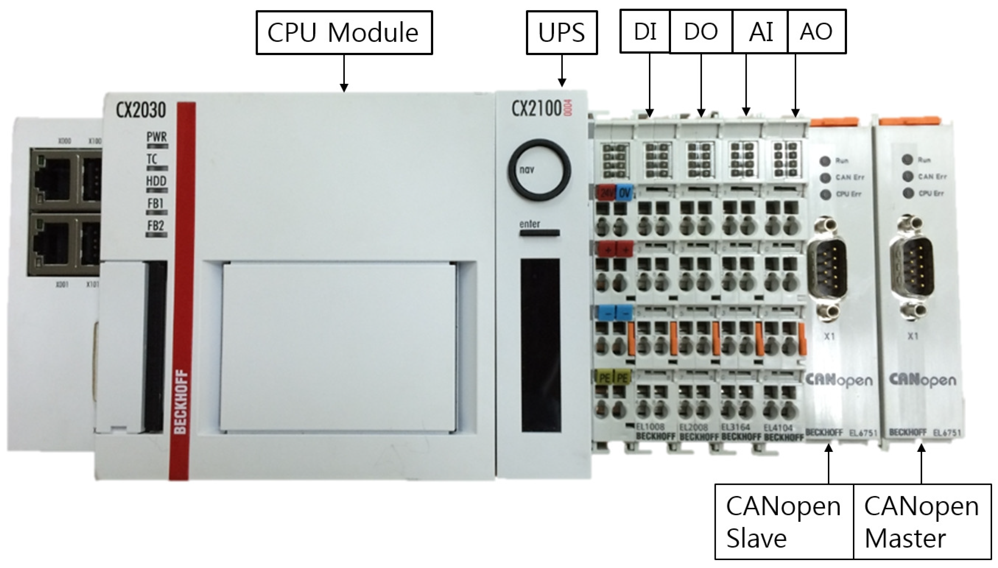
2.2.3. Hardware Design

The PCU is designed to perform the aforementioned functions (Figure 9). The TCU, PCU, and PDU are connected using the CANopen protocol. The PCU, as the CANopen slave, receives the control commands, such as the CPC angle from the TCU, which generates the final pitch control angle command as the CANopen master. The PDU, as the CANopen slave, receives the pitch control angle command from the PCU as the CANopen master, drives the pitch system, and returns the control results and status information to the PCU. The PCU delivers the information from the PDU to the TCU.
An analog input module for receiving the blade bending moment values and the blade azimuth angle from the sensors, the real-time simulator, a digital input/output module, and other mandatory components are required to perform the IPC function. The hardware platform for the PCU is constructed by using Beckhoff products that has been actually applied to the commercial wind turbine control system. The specifications of the platform components are shown in Table 1. As a development software tool, Beckhoff TwinCAT-3 (Beckhoff, Verl, Germany), which supports IEC 61131-3 standard programmable logic controller (PLC) language, is used.
Figure 10 shows the hardware platform of the PCU based on the Beckhoff platform, and the PCU hardware is implemented according to PCU requirement specifications.

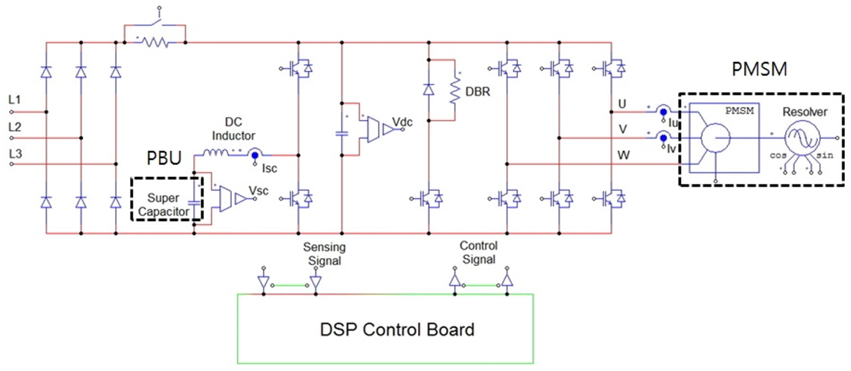
2.3. Pitch Drive System

The main components of a pitch drive system are an axis box and a pitch motor. The PDU located within the axis box consists of a power conversion circuit and a DSP control board, as shown in Figure 11. The power conversion circuit includes a rectifier, an initial charge current limit circuit, a DC-link smoothing circuit, a super capacitor charge/discharge circuit, a dynamic braking device, an inverter, and a motor brake power source.
The functions of the power conversion circuit are as follows. The rectifier rectifies the three-phase AC input voltage full-wave through the diode and supplies DC voltage to the inverter. When three-phase AC power is inputted to the rectifier in the state of no initial charging voltage in a capacitor of a DC-link smoothing circuit, large charging current can flow at the start of power input. The initial charge current limit circuit is used to protect the rectifier diode against damage.
A DC-link smoothing circuit is constructed by connecting a smoothing capacitor in parallel to an output terminal of the rectifier to reduce the ripple of the DC voltage supplied to the inverter. The super capacitor charge/discharge circuit charges or discharges the super capacitor that supplies the backup power needed to drive the blades to the feathering position to protect the wind turbine when the main power is lost. If the pitch motor decelerates, the motor operates as a generator and supplies energy to the DC-link terminal; the voltage of the DC-link terminal then increases. The dynamic braking device protects the circuit by forcibly consuming the regenerative energy as heat through the resistor. It suppresses the DC voltage of the DC-link terminal from being excessively raised by the regenerative energy.
The voltage-type pulse width modulation (PWM) inverter that converts a DC voltage to a three-phase AC voltage controls the rotational speed of the pitch motor by varying the amplitude and frequency of the voltage applied to the pitch motor. The motor brake power source is a chopper circuit for electrically restricting the motor rotation when the pitch motor must stop. The DSP control board converts the DC-link voltage, the motor current, and the resolver signals to digital signals for feedback and then generates PWM signals for controlling the pitch motor’s speed and position to the desired value. The DSP control board monitors the input signals, and if some signals exceeds the predetermined threshold value, it judges that the pitch motor is in an abnormal situation and performs an emergency action, such as tripping the PDU.

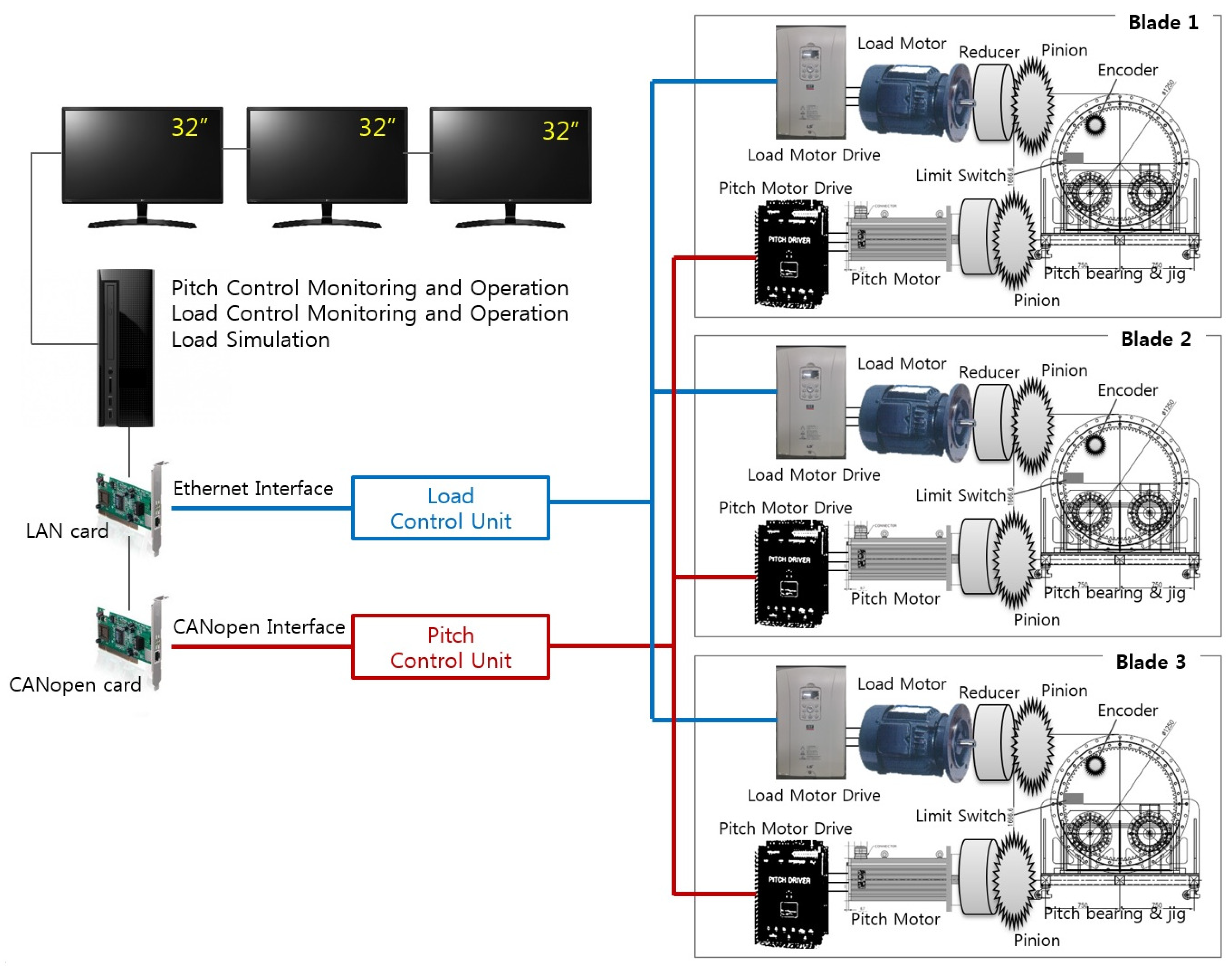
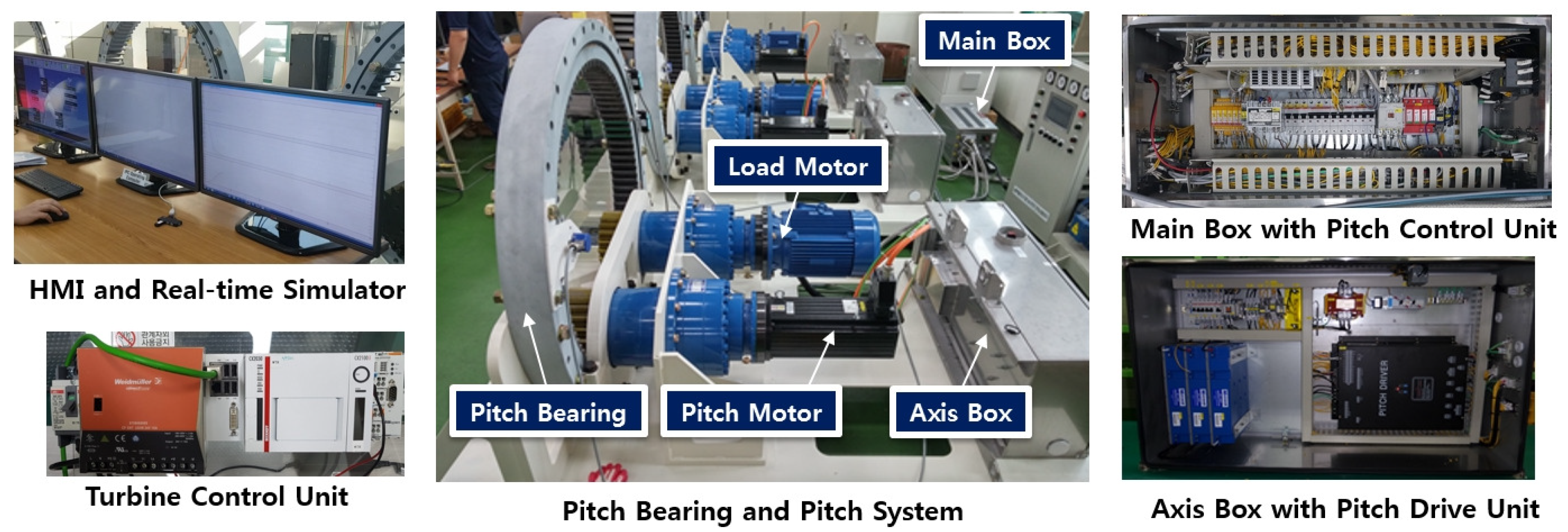
3. The Construction of Testbed
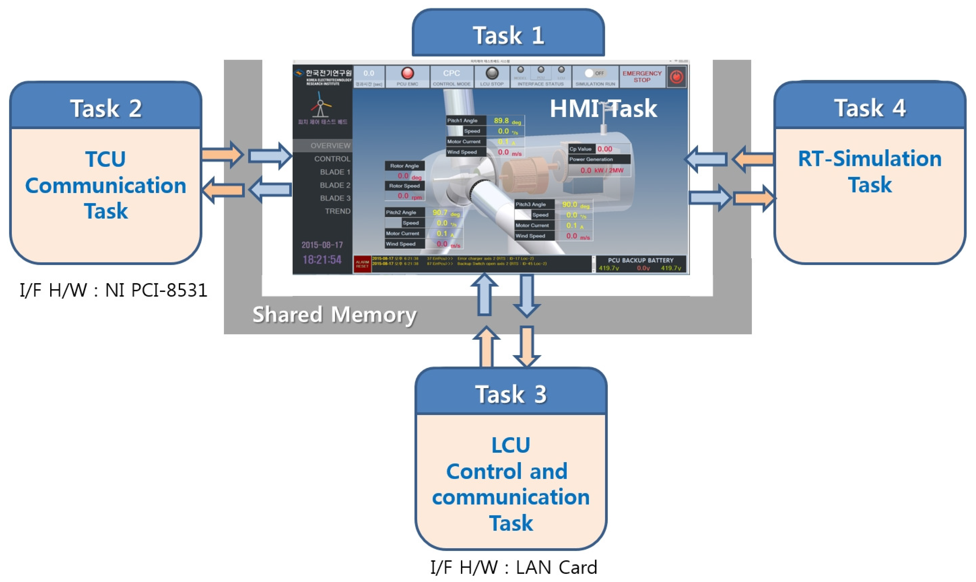
This paper’s testbed is constructed to evaluate the performance of the developed pitch system before it is applied to the actual wind turbine. Reasons for testing pitch controller performance by deploying HILS-based testbeds are as follows. The performance of a pitch controller includes not only the control algorithm, but also whether the control algorithm works successfully even if the controller is implemented in hardware and applied to the actual system. Although control algorithm performance has been successfully validated through offline simulations, it is not guaranteed that control goals will be successfully achieved by applying the controller to actual targets with several constraints, such as sensor noise and time delay due to the interface. It can be evaluated as a good controller to successfully achieve given control objectives while overcoming constraints under the actual environment. For these reasons, controllers are needed to be implemented with real hardware and tested on HILS based on real-time simulators which are similar to actual plants. The core of the testbed is a host computer that is a real-time wind turbine simulator. It contains a wind turbine model and mimics a real wind turbine, only except for the pitch system.
A wind turbine is modeled and based on the FAST (National Renewable Energy Laboratory (NREL), Golden, CO, USA) aeroelastic computer-aided engineering tool developed by the NREL and this paper’s target wind turbine model is selected as the NREL 5MW reference wind turbine model [19]. The simulator is merged with the developed pitch system to receive the pitch control results (i.e., the blade pitch angles measured in the pitch system). Based on the testbed, the performance of the pitch control algorithm can be evaluated. Moreover, the performance of the components of the pitch system under development can be evaluated and compared with the existing products through repetitive test procedures.
As shown in Figure 12, the testbed consists of a host computer, the developed pitch system, the wind load simulation system, and mechanical components such as pitch bearings, pinion gears, etc. The host computer has several functions, including operation of the testbed, monitoring of the status of the testbed, and simulating a wind turbine in real time.

3.1. Host Computer

The host computer is used as a human–machine interface (HMI) for monitoring and operation of the entire testbed. The real wind turbine system, only except for the pitch system, is substituted by the real-time simulation, and the real-time simulation function is also implemented using the real-time toolbox of MATLAB/Simulink (Mathworks, Natick, MA, USA). The computer with these functions can set various conditions for the performance test of the wind turbine system because it enables various wind turbine modeling and provides various wind conditions.
Figure 13 shows the configuration of the operating program running on the host computer and the communication structure between each task. As shown in Figure 13, the operating program shares data among tasks through shared memory and consists of four tasks. Task 1 is an HMI task that performs wind turbine system monitoring and operation functions. Task 2 is CANopen communication with the TCU. Task 3 is TCP/IP communication with a PLC of the wind load simulation system. Task 4 is a real-time simulation function for a wind turbine.
The real-time simulator program running on the host computer is the FAST model operated in real time. The model is linked and executed in the form of an s-function block under the MATLAB/Simulink environment by using the soft real-time function for real-time simulation [11,20].
Figure 14 shows a block diagram of FAST model. As shown in Figure 14, the wind profile which is pre-built by users in various forms and the pitch angles of the three blades transmitted from the actual pitch system are input to the FAST wind turbine block. In particular, if the wind input to the wind turbine model is to be configured in various forms such as wind shear, wind direction, gust, and so on, the variable value for the wind input disturbance setting in the FAST input file can be set to the desired wind setting [11]. The FAST model receives the generator torque value and the yaw angle of the nacelle as well as the pitch angles to solve the aerodynamic equation of the wind turbine model. As a result, the FAST model outputs the signals representing wind turbine operation, such as blade azimuth angle, rotational speed, blade root bending moments, and pitching moments. The generated values are transmitted to the pitch controller and to the wind load simulation system through the shared memory to be used for pitch control and wind load simulation.

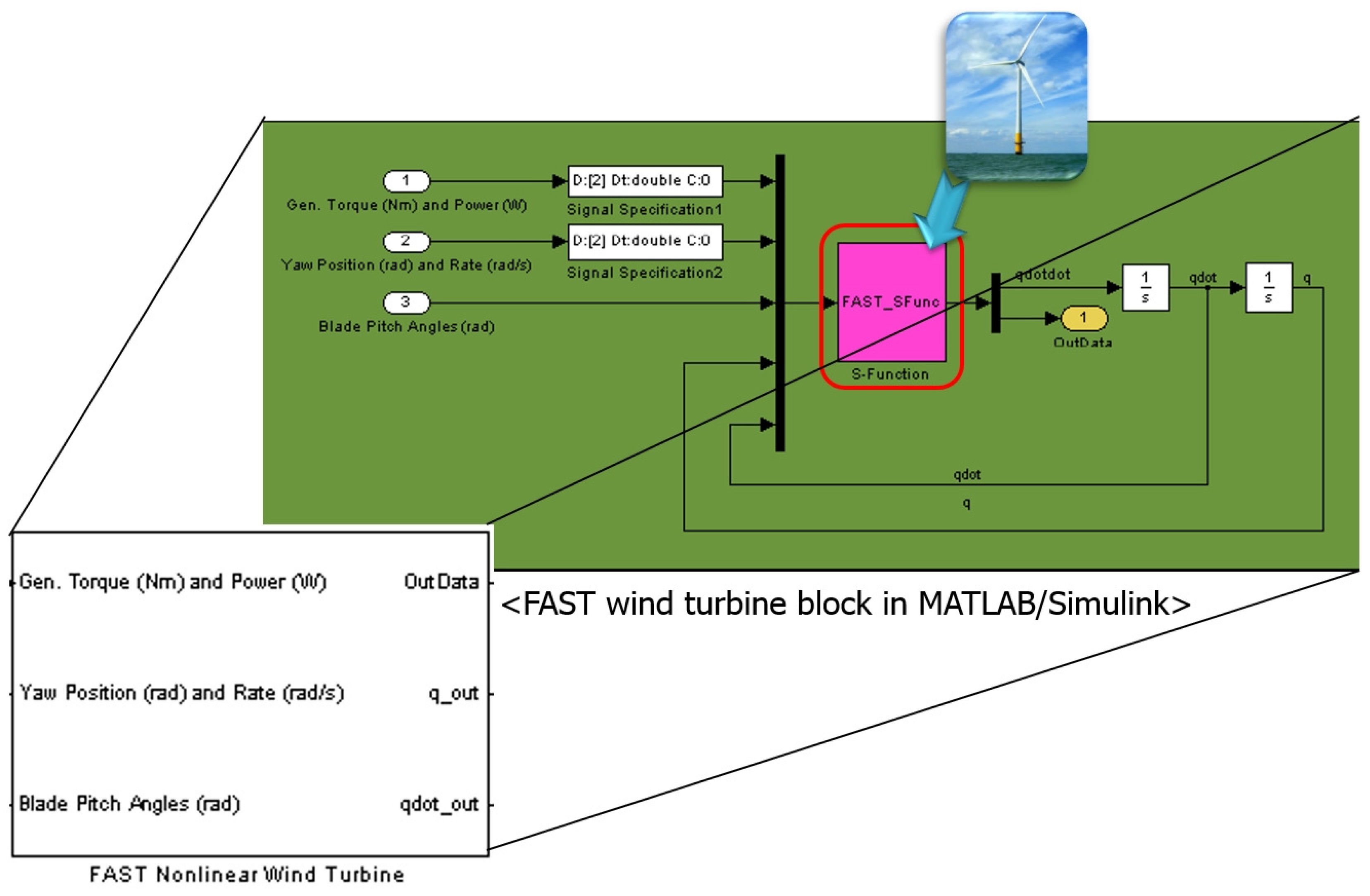
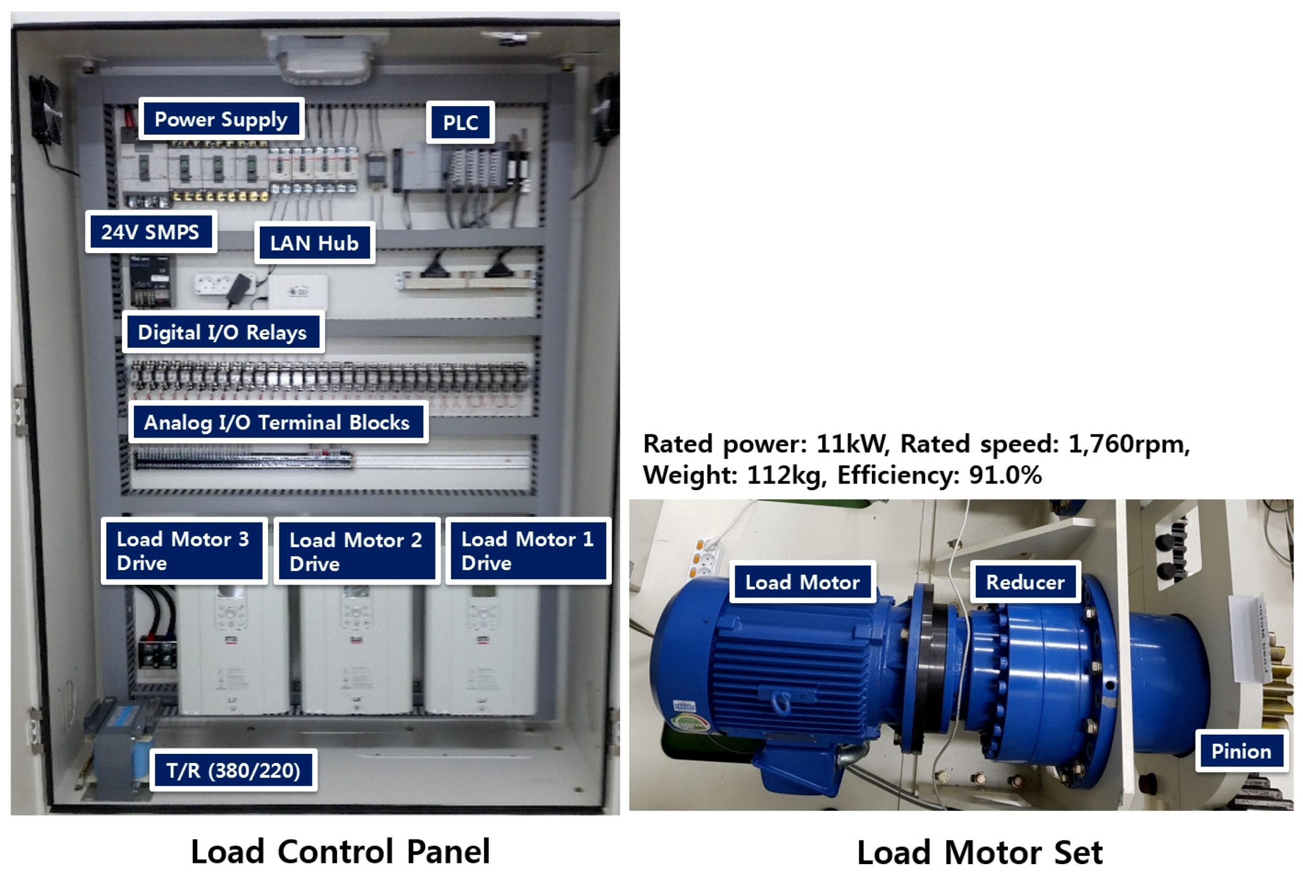
3.2. Wind Load Simulation System
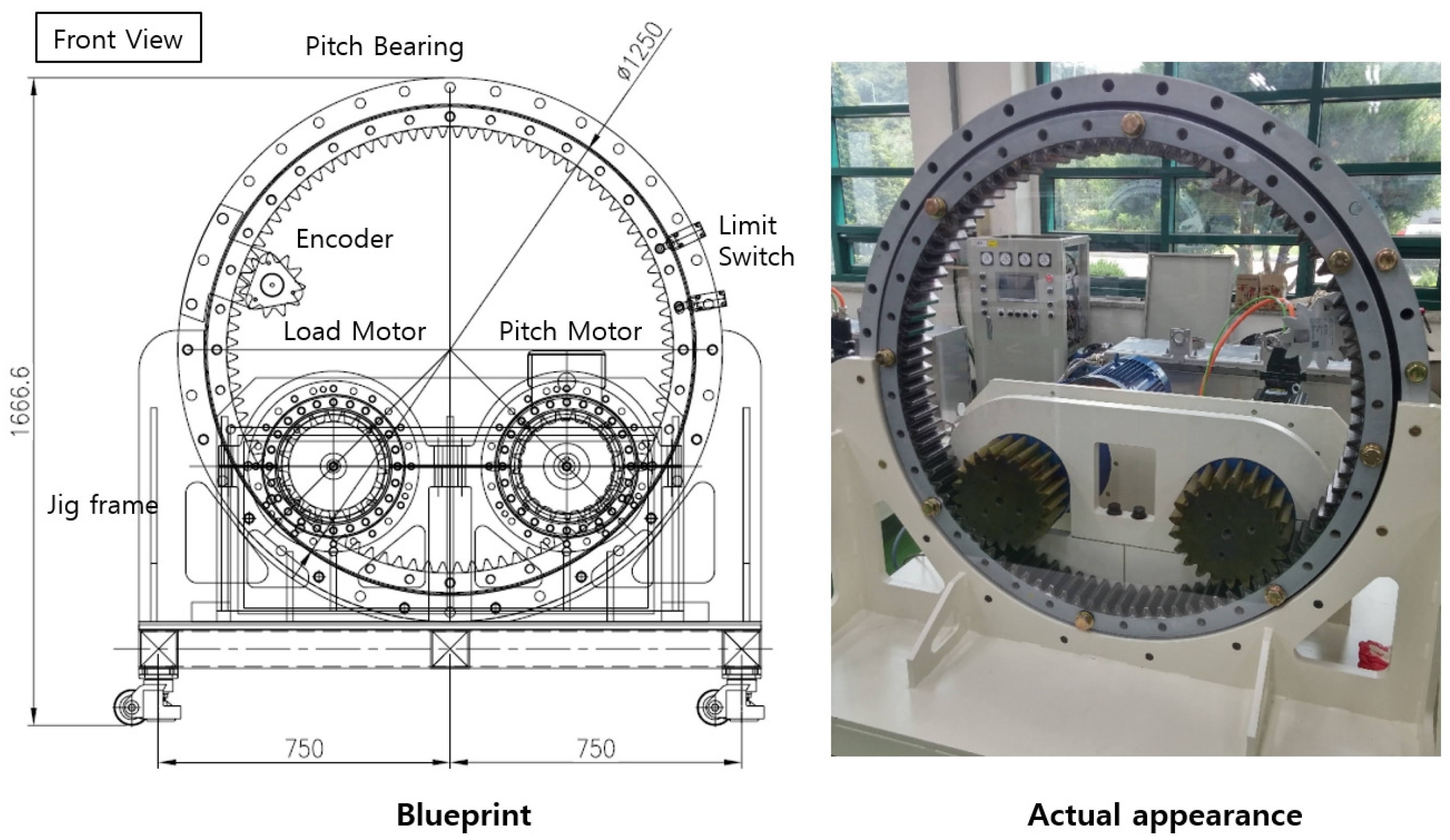
To evaluate the performance of the developed pitch system with wind blowing conditions, a system for simulating the wind load applied on the blades is installed with the pitch bearing. This wind load simulation system consists of a load motor, a load motor drive, a PLC for load motor control, a reducer, and a pinion for engagement with the pitch bearing, as shown in Figure 15.
The load motor uses a low-voltage, three-phase induction motor. The wind load applied to the pitch motor of the pitch system is determined by the blade weight, wind speed, and pitch angle and represented by the pitching moment generated by FAST [21]. When the pitching moment of the three blades generated through the real-time simulation is transferred to the PLC of the wind load simulation system through TCP/IP Ethernet communication, the PLC generates the commands corresponding to the pitching moment values. The load motor drive then performs torque control according to the PLC commands.
If the load motor simulates the wind load through this process, the pitch motor connected to the pitch bearing has to be controlled to follow the target pitch angle while overcoming the wind load, which interferes with the changes of pitch angles [22].

3.3. Pitch Bearing

The adjustment of the blade pitch angle is a result of rotating the pitch bearing. This is accomplished by controlling the torque of the pitch motor. The pitch motor and load motor are coupled with the pitch bearing via a speed reducer and a pinion. A jig frame is installed to support the pitch bearing, pitch motor system, and load motor system as shown in Figure 16. An encoder is attached to the pitch bearing to measure the rotation angle of the pitch bearing, and the measured value is transmitted to the pitch controller to perform the pitch control.

4. Test Results

In this section, the developed pitch system, as evaluated through the testbed, is discussed. Figure 17 shows the actual testbed and its components.
Figure 18 shows the test results of the pitch system. The result waveforms in Figure 18 represents the values generated by the pitch systems and MATLAB/Simulink-based FAST real-time simulator. One of the inputs to the testbed is the wind speed profile. At first, the wind speed is set to 10 m/s, which is below the rated wind speed ( 11 . 4 m/s) for 60 s. After that, the wind speed increases abruptly to 12 and 14 m/s at 60 and 90 s, respectively, to activate the pitch control mode [23]. After 300 s, the wind speed is rapidly decreased to 12 m/s. From 480 s, the wind speed is decreased linearly to deactivate the pitch control mode.
The control flow of the pitch angle below the rated wind speed (from 0 to 60 s as shown in Figure 18) is described as follows. Initially, the wind turbine does not operate with the pitch angle, which is at the feathering position (i.e., 90 degrees of the pitch angles). If the wind speed is between the cut-in and the cut-out wind speed for a certain time, the TCU sends a command to the PCU to gradually reduce the pitch angle from the feathering position to a fine position (about 5 degrees), which is sufficient for the blades to rotate. When the rotational speed of the generator reaches the minimum speed to start the wind turbine, the TCU makes the pitch angle reduce to the minimum so that C p of the wind turbine is maximized. If the minimum generator rotational speed is reached for the wind turbine power generation, the TCU sends the pitch control command to the PCU to keep the minimum pitch angle for achieving the maximum C p . The TCU calculates the target generator torque to generate the highest power with respect to the generator rotational speed for the MPPT operation.
If the wind speed exceeds the rated wind speed after 60 s, the output of the wind turbine is limited to the rated power. To do so, the TCU controls the generator with the rated generator torque and makes the PCU control the pitch angles to achieve the rated rotor rotational speed. This is achieved by CPC. Through CPC, the rotor rotational speed is maintained at 12 . 1 rpm in the region above the rated wind speed between 60 and 480 s. When the wind speed is gradually decreased to less than the rated wind speed from 480 s, the TCU reduces the pitch angles to the minimum for the MPPT operation. If the wind speed is below the cut-in speed, the TCU moves the pitch angles to the feathering position to stop the wind turbine.
When the PCU obtains the root bending moment of each blade from the wind turbine real-time simulator, it performs the IPC algorithm to reduce the root bending moment. Consequently, the load applied to the blades can be reduced. When IPC mode is on, the PCU adds the IPC angles to the pitch angles calculated by the CPC algorithm and delivers the total pitch angle commands to the PDU.
As shown in Figure 18, the IPC algorithm is on at 200 s and lasts up to 400 s. As shown in Figure 19, each pitch angle maintains the phase difference of 120 degrees each other at a period of 1P. As one blade rotates one turn, the pitch angle is maximized at the uppermost position, and the angle is controlled to be the minimum at the lowest position. The pitch angles shown in Figure 19 are measured by the encoder installed on the pitch bearing of the testbed and shows somewhat non-smooth results because the pitch motors are controlled by enduring the actually simulated wind load.
As seen in Figure 18, both the CPC and IPC algorithms try to keep the rotor rotational speed at the rated rotational speed in the region above the rated wind speed. The difference between the two control modes is found in Figure 20. Figure 20 shows that the bending moments in the IPC mode are smaller than those in the CPC mode. As a result, through the IPC function, the wind turbine keeps the output to the rated power and reduces the mechanical vibration load [24].

5. Conclusions

In this paper, a wind turbine pitch system is developed and tested in the HILS testbed. The developed pitch system can maintain the rotor rotational speed at the rated rotor rotational speed by collectively adjusting the blade pitch angles. Moreover, it can effectively reduce the mechanical load applied to each blade by individually adjusting each pitch angle to reduce the root bending moments in the region above the rated wind speed.
Before the developed pitch system is applied to a real wind turbine, reliability and performance verification is required. However, testing the developed system in the real wind turbine is practically impossible. As an alternative to this test, the testbed is constructed to simulate a real wind turbine in real time. The testbed consists of a real-time simulator for the wind turbine, a wind load simulation system for simulating the wind load, and actual mechanical components. The developed pitch system is installed and tested in the testbed. Through the test results, the developed pitch system is found to effectively perform its functions.
The authors declare no conflict of interest.

Author Contributions

All authors have contributed the developments of the pitch system and testbed. J.C. and J.K. conceived and designed the experiments; J.L. and K.L. performed the experiments; Y.C. analyzed the data; and J.C. wrote the paper.

Acknowledgments

This research was supported by the Korea Electrotechnology Research Institute (KERI) Primary Research Program through the National Research Council of Science and Technology (NST) funded by the Ministry of Science, ICT, and Future Planning (MSIP) (No. 19-12-N0101-19).

References

  1. Bianchi, F.; de Battista, H.; Mantz, R. Wind Turbine Control Systems: Principles, Modelling and Gain Scheduling Design; Advances in Industrial Control; Springer: London, UK, 2007. [Google Scholar]
  2. Senjyu, T.; Sakamoto, R.; Urasaki, N.; Funabashi, T.; Fujita, H.; Sekine, H. Output power leveling of wind turbine Generator for all operating regions by pitch angle control. IEEE Trans. Energy Convers. 2006, 21, 467–475. [Google Scholar] [CrossRef]
  3. Cheon, J.; Kwon, S.; Choi, Y. Design of a pitch controller using disturbance accommodating control for wind turbines under stochastic environments. In Proceedings of the 2014 IEEE 23rd International Symposium on Industrial Electronics, Istanbul, Turkey, 1–4 June 2014; pp. 2572–2577. [Google Scholar]
  4. Jing, Y.; Sun, H.; Zhang, L.; Zhang, T. Variable speed control of wind turbines based on the quasi-continuous high-order sliding mode method. Energies 2017, 10, 1626. [Google Scholar] [CrossRef]
  5. Park, S.; Nam, Y. Two LQRI based Blade Pitch Controls for Wind Turbines. Energies 2012, 5, 1998–2016. [Google Scholar] [CrossRef]
  6. He, K.; Qi, L.; Zheng, L.; Chen, Y. Combined Pitch and Trailing Edge Flap Control for Load Mitigation of Wind Turbines. Energies 2018, 11, 2519. [Google Scholar] [CrossRef]
  7. Corcuera, A.D.D.; Pujana-Arrese, A.; Ezquerra, J.M.; Segurola, E.; Landaluze, J. H Based Control for Load Mitigation in Wind Turbines. Energies 2012, 5, 938–967. [Google Scholar] [CrossRef]
  8. Selvam, K. Individual Pitch Control for Large Scale Wind Turbines-Multivariable Control Approach; Rept. ECN-E-07-053; Energy Research Centre of the Netherlands: Petten, The Netherlands, 2007. [Google Scholar]
  9. Kim, G.H.; Kim, J.Y.; Jeon, J.H.; Kim, S.K.; Kim, E.S.; Lee, J.H.; Park, M.; Yu, I.K. Hardware-in-the-loop Simulation Method for a Wind Farm Controller Using Real Time Digital Simulator. J. Electr. Eng. Technol. 2014, 5. [Google Scholar] [CrossRef]
  10. Caselitz, P.; Geyler, M.; Giebhardt, J.; Panahandeh, B. Hardware-in-the-Loop development and testing of new pitch control algorithms. In Proceedings of the European Wind Energy Conference & Exhibition, Athens, Greece, 27 February–2 March 2006; pp. 19–28. [Google Scholar]
  11. Jonkman, J.M.; Buhl, M.L., Jr. FAST User’S Guide; Technical Report No. NREL/EL-500-38230; National Renewable Energy Laboratory: Golden, CO, USA, 2005. [Google Scholar]
  12. Perng, J.W.; Chen, G.Y.; Hsieh, S.C. Optimal PID controller design based on PSO-RBFNN for wind turbine systems. Energies 2014, 7, 191–209. [Google Scholar] [CrossRef]
  13. Nam, Y. Control System Design. In Wind Turbines; Al-Bahadly, I.H., Ed.; IntechOpen: London, UK, 2011. [Google Scholar] [Green Version]
  14. Arnaltes, S.; Rodriguez-Amenedo, J.; Montilla-DJesus, M. Control of Variable Speed Wind Turbines with Doubly Fed Asynchronous Generators for Stand-Alone Applications. Energies 2018, 11, 26. [Google Scholar] [CrossRef]
  15. IEC Technical Specification 61400-13. Wind Turbine Generator Systems–Part 13: Measurement of Mechanical Loads, 1st ed.; International Electrotechnical Commission: Geneva, Switzerland, 2011. [Google Scholar]
  16. Markou, H.; Buhl, T.; Marrant, B.; Van Engelen, T. Morphological Study of Aeroelastic Control Concepts for Wind Turbines; STABCON Task-7 Report EU-Contract ENK5-CT-2002-00627; Energy Research Centre of the Netherlands: Petten, The Netherlands, 2002. [Google Scholar]
  17. Wright, A.D. Modern Control Design for Flexible Wind Turbines; Technical Report No. NREL/TP-500-35816; National Renewable Energy Laboratory: Golden, CO, USA, 2004. [Google Scholar]
  18. Van Engelen, T.; Van der Hooft, E. Individual Pitch Control Inventory; Technical Report No. ECN-C-03-138; Technical University of Delft: Delft, The Netherlands, 2005. [Google Scholar]
  19. Jonkman, J.; Butterfield, S.; Musial, W.; Scott, G. Definition of a 5-MW Reference Wind Turbine for Offshore System Development; Technical Report; National Renewable Energy Lab. (NREL): Golden, CO, USA, 2009. [Google Scholar]
  20. Vidal, Y.; Acho, L.; Luo, N.; Tutiven, C. Hardware in the Loop Wind Turbine Simulator for Control System Testing; Springer: Cham, Switzerland, 2014; pp. 449–466. [Google Scholar]
  21. Wang, C.S.; Chiang, M.H. A novel dynamic co-simulation analysis for overall closed loop operation control of a large wind turbine. Energies 2016, 9, 637. [Google Scholar] [CrossRef]
  22. Wang, C.S.; Chiang, M.H. A novel pitch control system of a large wind turbine using two-degree-of-freedom motion control with feedback linearization control. Energies 2016, 9, 791. [Google Scholar] [CrossRef]
  23. Imran, R.; Hussain, D.; Chowdhry, B. Parameterized Disturbance Observer Based Controller to Reduce Cyclic Loads of Wind Turbine. Energies 2018, 11, 1296. [Google Scholar] [CrossRef]
  24. Wright, A.D.; Fingersh, L. Advanced Control Design for Wind Turbines; Part I: Control Design, Implementation, and Initial Tests; Technical Report; National Renewable Energy Lab. (NREL): Golden, CO, USA, 2008. [Google Scholar]
Figure 1. The output power curve of a wind turbine according to the wind speed.
Energies 12 02031 g001
Figure 2. Configuration of this study’s pitch system.
Energies 12 02031 g002
Figure 3. The operation mode flowchart of the TCU and PCU.
Energies 12 02031 g003
Figure 4. The state machine of the PCU.
Energies 12 02031 g004
Figure 5. Blade rotating coordinate system.
Energies 12 02031 g005
Figure 6. The out-of-plane vibration of the rotor.
Energies 12 02031 g006
Figure 7. The principle of reducing load through IPC.
Energies 12 02031 g007
Figure 8. The overall design process of the IPC algorithm.
Energies 12 02031 g008
Figure 9. The hardware design of the PCU.
Energies 12 02031 g009
Figure 10. The actual hardware platform of the PCU.
Energies 12 02031 g010
Figure 11. The configuration of the PDU.
Energies 12 02031 g011
Figure 12. Configuration of the testbed.
Energies 12 02031 g012
Figure 13. Program configuration in host computer.
Energies 12 02031 g013
Figure 14. FAST wind turbine block in MATLAB/Simulink.
Energies 12 02031 g014
Figure 15. The configuration of the wind load simulation system.
Energies 12 02031 g015
Figure 16. The jig frame with pitch bearing, pitch motor system and load motor system.
Energies 12 02031 g016
Figure 17. The testbed view.
Energies 12 02031 g017
Figure 18. Test result waveforms (wind speed, pitch angle variation, blade rotation speed).
Energies 12 02031 g018
Figure 19. Pitch angle changes in the IPC mode.
Energies 12 02031 g019
Figure 20. Root bending moments.
Energies 12 02031 g020
Table 1. The specifications of the PCU.
ItemModelSpecification                  Remarks
CPU ModuleCX2030Intel Core i7 2610UE 1.5 GHz, dual core
Power Supply ModuleCX2100-000424VDC UPS
CANopen Master ModuleEL6751CANopen   1 , 000 kBaudrateFor Communication with PDU (the lower controller)
CANopen Slave ModuleEL6751-0100CANopen   1 , 000 kBaudrateFor Communication with TCU (the upper controller)
Digital Input ModuleEL10088 CH, EN61131-2, type 1/3For Communication with TCU (the upper controller)
Digital Output ModuleEL20088 CH, T O N : 60 μs, T O F F : 300 μs
Analog Input ModuleEL31644 CH, 0 10 V, ADC: 100 μsFor receiving sensor signals
Analog Output ModuleEL41044 CH, 0 10 V, DAC: 290 μs

