Review

Energy Management Strategies for Hybrid Construction Machinery: Evolution, Classification, Comparison and Future Trends

1
School of Mechanical and Aerospace Engineering, Jilin University, Changchun 130025, China
2
State Key Laboratory of Smart Manufacturing for Special Vehicles and Transmission System, Baotou 014030, China
*
Author to whom correspondence should be addressed.
Energies 2019, 12(10), 2024; https://doi.org/10.3390/en12102024
Submission received: 6 May 2019 / Revised: 19 May 2019 / Accepted: 22 May 2019 / Published: 27 May 2019
(This article belongs to the Section D: Energy Storage and Application)

Abstract

:
Hybrid Construction Machinery (HCM), known as an effective and crucial solution for the issues of environment pollution and energy shortage, has aroused increasing attention from manufacturers and researchers. A suitable energy management strategy is the vital technology to determine the energy saving and emission reduction performance of HCM. In the present paper, the difference between construction machinery and automobiles is first analyzed from the perspective of configuration, and the energy-based HCM configuration classification method is introduced and analyzed. Second, the development of HCM energy management strategy is reviewed along with relevant references, and the HCM energy management strategies are classified and summarized. In the meantime, the characteristics of each strategy are compared and analyzed, and the application of HCM energy management strategy is analyzed based on the relevant research results. Lastly, the state, challenges facing and the trend of HCM energy management strategy are analyzed on the levels of theory, manufacturer and market. According to the analysis, though progress has been achieved in energy management technology of HCM driven by market and policy, many challenges and problems remain in the electrification and intellectualization of HCM and the testing, application and improvement of the strategy. The contribution of this paper can be identified in three points: First, it can be referenced to solve relevant engineering problems. Second, it lays the foundation for the proposal of new ideas. Third, it highlights the state-of-the-art trends and avoids what has already been done.

1. Introduction

Originally conceived by the automobile industry, hybrid power technologies have become increasingly mature through decades of development. In the field of construction machinery, hybrid power technology is considered an important candidate to address the issues of high energy consumption and high emission. According to the development of hybrid construction machinery (HCM) in Figure 1 [1], the research of HCM had a relatively late start. With the introduction of hybrid technology from the automotive field and a large number of researchers that have devoted themselves to related research, HCM has developed rapidly over the past decade.
A few reviews have been published about HCM systems, which can be summarized as follows. In [2], the differences between construction machinery and automobiles in working mode, key components and actuators were highlighted, and the HCM prototypes developed by the world’s major manufacturers before 2010 were reviewed. The classification and structural characteristics of energy storage systems were introduced in [3]. Based on the above works, hybrid electric excavator, loader, forklift, bulldozer and crane systems were introduced in [4]. The existing review papers have mostly analyzed and compared the structural characteristics of HCM systems and subsystems. In addition, there has been no systematical and comprehensive overview of energy management strategies in HCM hybrid technology.
Compared with common automobiles, construction machinery is characterized by lower travel speed, more obvious periodicity, higher amplitude and load change rate, more complex systems and structures, as well as more frequent start-stop operations [1,2], as listed in Table 1.
Besides, the duty cycle (defined as the proportion of high load status to total period) of actuators is low (e.g., under typical operation cycle, the duty cycle of a wheel loader is only about 60%, and the remaining time is in a low load or non-load state [4]). A large number of actuators participate in the operation process, making the working conditions, systems and structures of construction machinery more complex than those of automobiles. Besides, there are many differences between different construction machineries, further increasing the complexity of the problem. Accordingly, the characteristics of construction machinery should be fully captured and hybrid power systems suitable for construction machinery should be developed.
In this paper, the configuration of HCM is first classified and analyzed according to the system characteristics. On that basis, the research and application of energy management strategies of HCM are qualitatively analyzed through classification and comparison to reveal the principles and characteristics of each strategy. Finally, the development status, trends and future challenges of HCM energy management strategy are studied from the theoretical perspective and on manufacturer (market) level.
The rest of this paper is organized as follows: in Section 2, the classification method of HCM is introduced. In Section 3, the hybrid power energy management strategies used in the field of construction machinery are classified and compared. In Section 4, the development and trend of HCM energy management strategies from different perspectives of researchers and manufacturers are discussed and analyzed. In Section 5, the conclusions of this paper are drawn.

2. Configuration of HCM

HCM, as a composite system, integrates knowledge about machinery, electricity, heat, liquids and chemistry. During its operation, complicated power flow, energy flow and information flow are generated, transmitted and transformed. Configuration is the basis of hybrid power system design, determining the development and selection of energy management strategy. Thus, it is necessary to differentiate the configuration of hybrid power systems in a reasonable manner before studying the energy management strategy for HCMs.
According to the structure, the hybrid electric vehicle (HEV) transmission system is split into series, parallel and series-parallel (power split). Due to the existence hydraulic actuators in HCM, the system configuration topology is a two-dimensional matrix, consisting of drive train and hydraulics, as shown in Figure 2. However, in a HCM system, this two-dimensional configuration expression is not only cumbersome, but also lacks any description of the energy characteristics of the system. Besides, it is not clearly expressed because of the lack of description of the energy characteristics of HCM system. Accordingly, applying the classification concepts of HEVs directly to HCMs may complicate the accurate expression of the configuration.
To deal with the classification problem of HCMs, according to the type of hybrid power-energy source, they are classified into three types, including Diesel-hydraulic hybrid (DHH), Diesel-electric hybrid (DEH) and fuel cell hybrid (FCH). This classification method reflects the ways and characteristics of energy conversion, storage and utilization in each HCM system. In a HCM system, the energy generating device covers ICE and fuel cell, and the energy storage system (ESS) primarily includes storage batteries, super capacitors and hydraulic accumulators. The performance characteristics of energy storage devices (as shown in Figure 3) lay a solid basis for HCM to formulate energy management strategy constraints. Thus, the combination of energy-based and structure-based classification in Table 2 can help to achieve a more accurate and reasonable description of HCM system configuration.

2.1. Diesel-Electric Hybrid

According to the definition of the International Electrotechnical Commission, a HEV is a vehicle with two or more forms of energy reserves, one of which can be converted into electric energy [10]. Like HEVs, DEH adopts a battery or ultracapacitor as ESS [6]. The use of fossil energy is reduced in DEH by combining hydraulic energy and electric energy during operation. The DEH structure consists of ICE, generator, battery /ultracapacitor, motor and hydraulic actuator. Under this structure, the ICE converts the energy of diesel oil and charges the ESS [11].
In the recent decades, the continuous development of HEV technology has stimulated the use of DEH in HCM. The hybrid excavator has been outfitted with the capacitor to balance the fluctuation of the power required by the hydraulic system and to store the regenerative energy of the hydraulic motor-generator and the swing motor [12]. However, due to the low capacity, capacitors cannot easily satisfy the requirements of HCM systems. Referencing the design idea of HEV [13], the series and parallel topologies of DEH are shown in Figure 4 and Figure 5, respectively [14,15].
In [15], by combining test and simulation, the performance of excavator in series, parallel and conventional structures is compared, in which the series structure adopts Figure 4d and the parallel one follows Figure 5d. The comparison results of [15] reveal that the ICE in series structure performs better under heavy load mode, because ICE is not coupled with actuators or affected by load fluctuation. Furthermore, if the economy is further considered, the current in the series structure changes more dramatically than in the parallel one, which negatively affects battery life and increases maintenance costs. It is considered that parallel structure is more applicable to hybrid excavators. Accordingly, the structure of Figure 5d is presented in relevant studies [16,17].
However, the impact of the frequent changes in HCM load on battery-based ESS may be greater than expected. For instance, it only takes 2–3 sec. for the excavator boom to descend, during which the electrochemical reaction process of the battery is slow (typical response time ranges are 2–3 s [18]), and the high power charging is difficult [3]. Thus, frequent high-power and fast impulse/discharge of energy is a problem to be solved for battery as ESS in HCM. Compared with batteries, ultracapacitors possess the characteristics of fast response (with a response time of milliseconds [19]), higher power density and better temperature adaptation [20]. Ultracapacitors are more efficient than batteries because there is no chemical reaction during energy storage. The progress of the preparation technology of mesoporous materials improves the performance of ultracapacitor [21] and promote the structures in Figure 4b and Figure 5c applied in engineering [22,23].
In view of the problem of low energy density and high cost of ultracapacitors, a scheme combining battery and ultracapacitor was proposed [24,25], in which the battery and ultracapacitor were connected in parallel on DC bus like in Figure 4a. The energy allocation of the system by thw ultracapacitor can decrease the battery cycle and power ramp rates, thus improving the comprehensive performance of ESS, but in this case, the limitation of voltage change from battery affects the energy recovery of the ultracapacitor. Hredzak [26] et al. adopted two bidirectional DC/DC converters. Ultracapacitor and battery can be charged and discharged independently, enhancing the flexibility of the energy management control strategy. The ultracapacitor is regarded as an energy buffer to ensure stable battery charging and discharging [27]. The combination of ultracapacitor and battery is complementary and reduces the capacity requirement of the ultracapacitor, thereby reducing the cost. Nevertheless, some problems remain regarding installation space and weight, and the addition of different energy storage devices may increase the difficulty of energy management.
In the design of ESS for DEM, several aspects (e.g., capacity design, charging and discharging power and voltage design) should be considered. Given the corresponding characteristics of ESS, the total capacity should match the requirements of continuous charging and discharging. Besides, the system voltage should be matched with the motor and transformer used. The maximum charging and discharging power required can be obtained from the power spectrum analysis of working conditions and ensured when designing the charging and discharging current of battery packs or ultracapacitor. Then, according to the requirements of capacity and charging and discharging current, the battery or ultracapacitor can be selected reasonably.

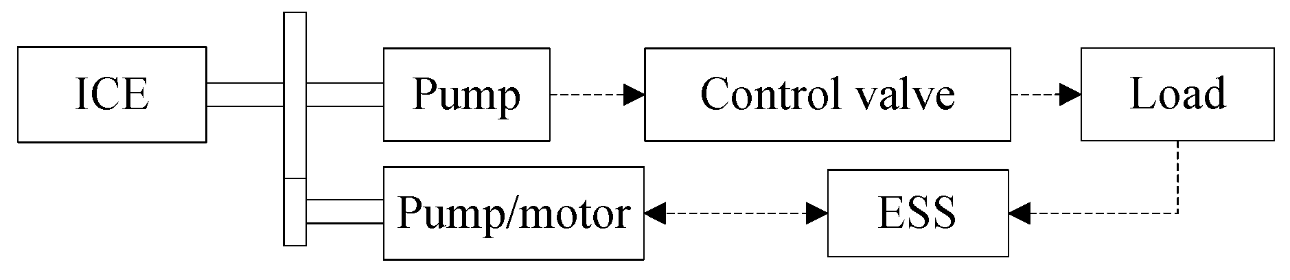
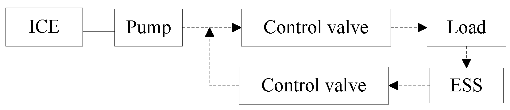
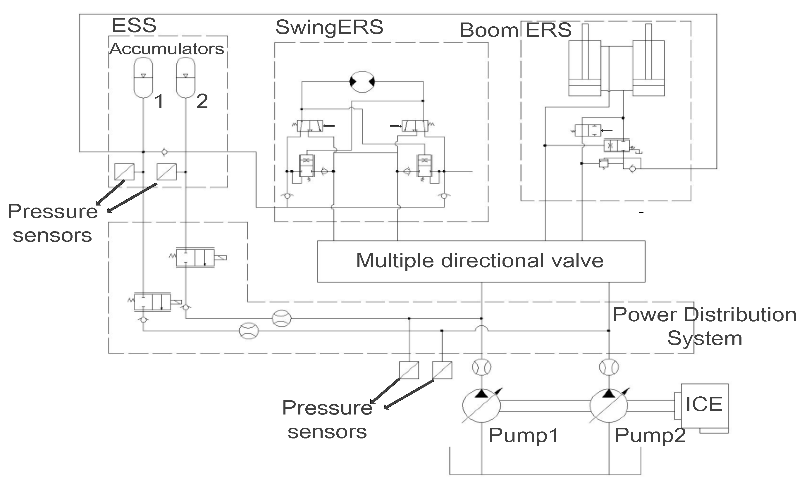
2.2. Diesel-Hydraulic Hybrid

Considerable electric power and electronic equipment have been added to DEH systems, increasing the difficulty and cost of system transformation. In engineering applications, DHH systems were used in the initial stage of technology introduction. The difference between DHH and DEH lies in the types of ESS and energy flow, i.e., hydraulic system, hydraulic pump/motor and hydraulic accumulator act as auxiliary power source components. As a type of hydraulic energy storage device, an accumulator is also used as the hydraulic counterbalance of the boom to balance the gravity of the working device [28]. In DHH systems, hydraulic energy can be converted into mechanical energy through a hydraulic pump/motor and couple with the energy output from the ICE to form a "torque coupling structure” (TCS) similar to a parallel DEH [29], as shown in Figure 6. On the other hand, the hydraulic energy between accumulator and main pump can also be coupled directly, which is termed as a "flow coupling structure” (FCS) [30], as shown in Figure 7.
In the design of DHH, to meet the design requirements of the system, additional accumulators were added in the DHH system, and different effects were generated. A TCS system with double accumulators was applied in [31] and [32], as shown in Figure 8. High-pressure (HP) accumulator was used to recover and store excess energy of ICE, braking energy of rotary motor and energy recovered from the cylinder circuit, which could generate the torque for the system through a hydraulic pump/motor working in the motor mode coupled with the engine or provide oil for the rotary motor in the form of flow coupling when the rotary motor starts. The additional low-pressure (LP) accumulator was not used for energy storage but rather used as a low pressure flow source to achieve the balance of the flow of each cylinder. The simulation results suggest that the system can save up to 27% of the fuel consumption compared with the non-hybrid system. In [30], a FCS system with two accumulators was introduced, as shown in Figure 9. The two accumulators were used to recover the potential energy of the boom and the rotating braking energy, respectively, and the flow can be shared between the accumulators to maintain the ideal state of charge (SOC) and maximize the energy recovery. For instance, when the pressure of the boom potential energy recovery accumulator is too large, the excess oil recovered can be transferred to the rotary brake energy recovery accumulator. When the revolutions start and the boom rises, the accumulators will release the stored oil to the outlet of the hydraulic pump, which attempts to supplement the power required in the instantaneous start-up and reduce the power demand of the hydraulic pump for energy saving. The energy-saving effect of the system could increase to 10.1% with appropriate flow distribution control strategy. In other designs, excessive throttling of FCS hydraulic system was avoided, and throttling loss was reduced by introducing a new valve configuration with two pressure levels of accumulator, medium pressure (MP) and high pressure (HP) [33].
In addition to multi-accumulator systems, a hydraulic/electric synergy system composed of accumulators and batteries was proposed [34,35]. As the boom of an excavator descends, the starting and stopping state of the engine depends on the pressure in the accumulator and does not affected by the boom. In this process, the accumulator limits the operating point of the ICE to an efficient field, allowing the system to apply lower power engines and motors. Furthermore, the impact of energy flow is absorbed by accumulator, decreasing the change rate and the amplitude of charging current. The time to regenerate energy is significantly increased from 2 sec. to 20 sec. Compared with DEH, the hydraulic/electric synergy system further reduces the cost.
Compared with DEH, DHH technology involves less energy conversion behavior, reducing the energy losses of the system. Besides, the hydraulic/electric synergy system can further reduce the cost. Moreover, in the trend of technology upgrading and stricter emission standards [36], FCS, because of its low cost of system modification, has promising applications in remanufacturing. The coupling condition of accumulator and the major hydraulic pump in FCS is that the former pressure is greater than the latter’s outlet pressure, limiting the reuse of energy.

2.3. Fuel Cell Hybrid

As one of the alternatives to ICE in the future, the application of fuel cells in engineering machinery is also being developed [36,37], during which the characteristics of fuel cell should be considered. Take the proton exchange membrane fuel cell (PEMFC) as an example, in which the pressure and humidity should be controlled using the corresponding devices. The dynamic response of PEMFC is slow due to the limitation of the reaction speed of the devices. In the case of abrupt load change, the response delay will cause the output voltage and current of fuel cell to not change rapidly with the energy demand of the system. Accordingly, it is necessary to consider the system response delay in the application of fuel cell technology.
One of the effective ways to solve the mentioned problems is to compensate the response lag of fuel cell system by exploiting the high responsiveness of ESS, which is termed a fuel cell hybrid (FCH) system. In [38], the topological system for a FCH was given, as shown in Figure 10, and its structure is more concise than that of diesel hybrid power system. The power of conventional ICEs in construction machinery was replaced by the power of fuel cells and ESS. Due to the fact the working point of a fuel cell varies with the capacity of the fuel cell and ESS, the capacity of the fuel cell and ESS should be allocated in a reasonable manner with the power demand is met. In [39], a strategy of optimal capacity allocation for FCH excavators based on dynamic programming was proposed. The simulation results show that as the number of cells increases, the hydrogen fuel consumption decreases, the final SOC of ESS is easier to maintain at a set value. However, too many cells will reduce the power consumption of ESS and make the SOC unsustainable. Following this strategy, the optimal solution was obtained from three aspects of comprehensive evaluation, including final SOC, fuel cell efficiency and cost.
Furthermore, the load change and start-stop cycling are the primary factors leading to the performance degradation of fuel cells [40]. The efficient use of ESS is the key to reduce the impact of variable load and start-stop cycle on fuel cell life. Zhang [41] et al. proposed a DC bus voltage control energy management strategy and applied it in a FCH forklift. This strategy, due to the reaction delay of fuel cells, could prevent voltage overshoot or undershoot during the charging and discharging process of ESS, thus protecting the system and enhancing efficiency.

2.4. Comparative Analysis

In DHH, the response speed of a pump-controlled speed governing system is slower than that of a DEH system (e.g., in general, the torque response time of an integrated starter and generator (ISG) motor is less than 100 ms [42], while the displacement response time of hydraulic pump is more than 200 ms). Thus, a control valve is required to increase the response speed of the system. Furthermore, the pressure loss along the hydraulic circuit and the compressibility of hydraulic oil lead to the long pressure buil-up time of hydraulic systems. As hydraulic components have been extensively employed, the energy loss of the system and the cost of inspection and maintenance are increasing. Moreover, in the process of torque control, DHH system lacks an appropriate means of torque feedback. As a whole, the discharge is estimated by the hydraulic motor with displacement feedback ability of a valve core. The calculation accuracy cannot be ensured, bringing difficulties to the lower control (e.g., PID). Besides, the problems (e.g., space occupancy, vibration and noise) in DHH systems remain to be solved. For instance, the hydraulic pressure generated in hydraulic pumps (piston pump or gear pump) in construction machinery is achieved by the variation of local volume, leading to higher space requirements for hydraulic pumps and making the systemic integration more difficult to achieve. Furthermore, the alternation and sharp nature of hydraulic fluid fluctuations, caused by periodic variations of the working volume, will cause vibration and noise in the system, thus affecting the performance and reliability of DHH system. By replacing the hydraulic system in DHH with electric power system, DEH can make the structure design more compact and contribute to lightweight improvement. However, the electrification degree of conventional construction machinery is generally low, and the design is conservative. On the other hand, the DEH system needs to add additional X-by-wire system, electrical components, etc., and significantly modify the conventional system. Variation of DC bus voltage of large-scale inverters will affect itself and motors (e.g., loss of torque, increase of current, low-frequency harmonic distortion of motor power supply, etc.). Accordingly, the energy loss of the inverter and the temperature rise of the motor are the problems to be considered in DEH. Moreover, to ensure the safety and the reliability of batteries, overcurrent and overvoltage should be avoided. Compared with the above two configurations, there is no emission pollution problem in FCH. However, as a new concept, the development and application of FCH remain subject to the following problems: (1) cost control; (2) hydrogen production; (3) safe transportation and storage of fuel; (4) construction and layout of supporting facilities. Through the development of FCH technology, more choices and possibilities are created for future HCM.

3. Energy Management Strategy of HCM

The basic requirement of energy strategy design in a HCM system aims to achieve efficient energy recovery and reuse on the premise of ensuring high reliability of system control and efficient transmission of different energy flows in the system. Besides, to optimize the control strategy, the efficiency of ESS in different configurations should also be considered. The SOC was defined as the ratio of residual capacity of battery/ ultracapacitor to total capacity, a vital parameter used to characterize the state of battery and ultracapacitor in DEH. In DHH, the SOC of accumulator was defined as the ratio of instantaneous fluid volume to maximum fluid capacity in accumulator, which could be estimated according to outlet pressure when the temperature is relatively stable [43].
In this paper, according to the existing research results, HCM energy management strategies were separated into two types, namely rule-based strategies (RBSs) and optimization-based strategies (OBSs). The specific classification is shown in Figure 11. Next, the energy management strategies are introduced based on the related research.

3.1. Rule-based strategies

The rule-based strategies (RBSs) are to virtually ensure the ICE remains in a more efficient working state by introducing a motor system that fluctuated with load power, in an attempt to save energy and reduce emissions. The existing HCM power management strategies are primarily rule-based, which can easily switch operation modes and deal with the constraints and non-linear problems. The rules can be designed and formulated according to the prior knowledge, heuristics, the certain model and even intuition. Thus, RBSs are also termed "heuristic strategies". Without considering the overall efficiency of the power system, RBSs can optimize the working point in real time and determine the working period in advance, allowing for the wide application of RBS in developing HCM energy management system. RBSs could be split into deterministic rule strategies (DRSs) and fuzzy rule strategies (FRSs).

3.1.1. Deterministic rule strategies

In DRSs, the working state of the main/auxiliary power source is divided base on the working mode, and the rules are a series of logical expressions corresponding to the state. According to the research and applications in the HCM field, DRBs can be subdivided again into thermostatic strategies (TSs), power follower strategies (PFSs) and combinatorial strategies (CSs).
1. Thermostatic Strategies
The principle of TSs is that once the ICE is turned on, the operating point will enter the high efficiency area quickly and then keep working at the optimum operating point until the SOC of ESS reaches the set upper limit. These strategies were mostly applicable to PSHEV and SHEV [44]. In some cases, TSs are also called “on/off strategy” in series HEV [45] and “constant operating point strategy” in series parallel HEV [46]. TSs make the ICE speed independent of the vehicle speed and output power. The power peak was adjusted by ESS to meet the instantaneous power demand of power system. In HCM, safety thresholds of SOC should be defined to prevent against over-charging caused by the drastic change of the load. The selection of threshold had far-reaching effects on the component duty cycle and fuel efficiency [45]. According to [47], charging and discharging of ESS are a transient process, and the main concern of TSs are how to keep SOC above the absolute minimum. As input of a control system, SOC and power requirement are prone to large fluctuations of ICE speed due to the drastic change of loads in a short time, affecting work efficiency. To address this problem, Lai [45] et al. blurred the values of SOC, power requirement and accelerator location in a series DEH excavator system to enhance robustness of TSs and ensure the stability of the working point.
2. Power Follower Strategies
In PFSs, the output power of ICE-generator unit should satisfy the load requirement of the working conditions. From the macroscopic perspective, the following behavior of working points in PFSs could be defined not only in an efficient interval, but also along a curve or even switching between discrete points. The operating point of ICE-generator unit was determined by the values of SOC and load demand power. In DEH and DHH with series topology, there was an energy coupling relationship between ICE-generator set and motor drive system, i.e., there was no direct mechanical relationship between ICE speed and operation speed. For this reason, the ICE, according to the power requirement and the universal characteristic curve, could be controlled by PFSs to operate in different ways in the fuel economy point, line or zone. Similar strategies, called "Baseline Control Strategies (BCSs)", were also applied in parallel HCM [48]. In [17], a three-operation-point energy management strategy based on BCSs was proposed. Beside the major operation point, the strategy set two additional working points, corresponding to the heavy and the idle load state, respectively. To enhance stability and efficiency of the system, the switching of working points was based on the upper and lower thresholds of SOC. However, the points selected according to the constraint of SOC in this multi-point energy strategy cannot ensure that ICE is in an efficient working area while the work point is switched, thereby affecting the stability of the system. Besides, the response speed of the system should be high. Furthermore, PFSs did not consider the efficiency of power assembly components and fuel consumption/emission minimization policies, thus affecting the performance of the strategy.
3. Combinatorial Strategies
The comparison of TSs and PFSs control logic in Table 3 clearly shows that the ICE started and stopped more frequently, which was not conducive to good performance or lifetime of the ICE. In PFSs, the ESS energy flow varied stably, and there was no high proportion release. Compared with PFSs, TSs avoided the frequent starting and stopping of ICE, making the operating point more stable. However, the energy flow in ESS fluctuated significantly, and a high proportion of charging and discharging occurred frequently, affecting the efficiency and life of the ESS. Accordingly, CSs were developed by combining the above two types of strategies. In CSs, the high efficiency area of engine and battery was utilized to improve system efficiency while avoiding the adverse effects on the ICE and ESS, respectively. In [49], CSs was applied in a DEH forklift system. The system was split into two parts: a potential energy recovery system and a brake recovery system, PFSs for the former and TSs for the latter. The comparison of the simulation and test results of the conventional hydraulic forklift suggests that the hybrid power system under the control strategy had a significant energy-saving effect.

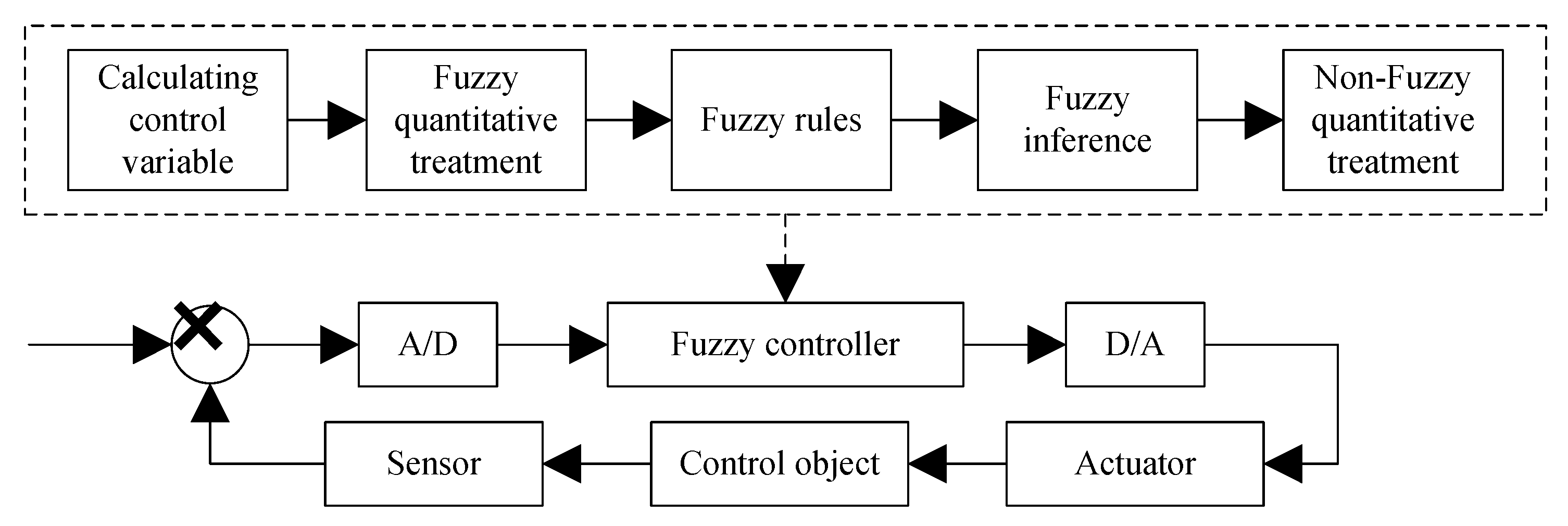
3.1.2. Fuzzy rule strategies

The DRSs were characterized by simplicity and high coding efficiency. In the case of the stable ICE state, motor characteristics and operation conditions, the ideal control effect could be obtained. Besides, the result of DRSs remains unsatisfactory due to the following two shortcomings: (1) DRSs were based on engineering intuition. The non-linear characteristics of HCM dynamic system were difficult to describe, leading to the inadequate exploitation of the energy-saving potential of the hybrid system. (2) The determination of the working threshold values of ICE and ESS was based on numerous experiments, and meantime the threshold fixed control method exhibited poor adaptability to the change of working conditions or parameter drift [45]. In view of the multi-mode, non-linearity and strong time-varying characteristics of HCM hybrid power system, the second shortcoming was the major factor affecting the application of DRSs in HCM.
Fuzzy rule strategies (FRSs) can be considered as an extension of DRSs. In fact, FRSs defined the static relationship of nonlinear between inputs and outputs. The control objectives of FRSs and DRSs were almost the same, while the major difference was in the expressions of various thresholds. In FRSs, a fuzzy control rule was established based on Mamdani rule based on the engineering experience and experimental characteristics of key power components. FRSs exhibited high robustness and adaptability to the nonlinearity and load variation in HCM system. The application of FRSs in HCM is shown in Figure 12. In [50], the movement speed of the manipulator was controlled by adjusting the electromagnetic torque of the generator with a fuzzy-PID control strategy, thereby enhancing the efficiency of energy recovery in a DHH excavator. The simulation results suggest that the efficiency of energy recovery was enhanced by about 10% compared with that using only PID control. In FRSs, the precise mathematical model of the controlled object was not required. However, the design of fuzzy rules and membership functions required a lot of experience and constant debugging.
In addition, to enhance efficiency and performance of RBSs, the controller should be adjusted according to the load cycle. This suggests that it is not feasible to adopt a specific rule-based energy management strategy directly under all types of operating conditions with different operating cycles. RBSs could easily achieve on-line and real-time energy management. However, it was difficult for RBSs to achieve optimal results when addressing common multi-control objective problems [51]. Besides, the input parameters were blurred in FRSs, making it easier to compromise ICE efficiency, motor and ESS, and to coordinate the dynamic, economic and emission performance of HCM.

3.2. Optimization Based Strategies

Considering the system components instead of the system itself, there was uncertainty and blindness in the improvement process of RBSs. This helped the development and application of optimization based strategies (OBSs) in HCM. OBSs optimized the control objectives by defining cost functions and imposing constraints. In this process, not only fuel consumption could be selected for single objective control, but also emission, SOC and fuel consumption could be selected for multi-objective optimization control.

3.2.1. Global Optimization strategies

Global optimization strategies (GOSs) aim to dynamically distribute the power output of the ICE and motor in accordance with the optimal control theory under the given operation cycle, in an attempt to optimize the fuel economy and other indicators. Most hybrid power systems use dynamic programming (DP), in accordance with Bellman dynamic programming theory, to yield a global optimal solution [52]. In fact, DP is a type of non-linear programming. Its principle can be summarized as a type of recursive relationship, different from that of the rule-based control strategy. The process of formulating optimal control strategy by DP depends on dynamic model.
Though HCMs exhibit obvious periodic characteristics compared with HEVs during operation, their working conditions are more complex, and the working period is highly non-linear, thereby increasing the difficulty of state selection, decision-making and determination of the state transition law. In [53], a genetic algorithm (GA) was used to avoid describing the model of the system when selecting the energy storage type of parallel hybrid excavator and determining the optimal speed of ICE.
As a "greedy" traversal algorithm, DP was sensitive to the number of variables: the computation of model solution will increase exponentially with the rise in the number of state variables or control variables, called “Dimensionality curse”, which makes DP optimization more difficult to achieve. Intelligent algorithms, e.g., particle swarm optimization (PSO), provide people with more choices. In [16], an optimal control method for parallel DEH excavators based on PSO was proposed, which was used to deal with considerable non-linear optimal problems under inequality constraints in the energy management system of parallel hybrid excavators, and the optimal structure was used as a performance benchmark to assess the rule-based optimal control strategy.
GOSs can be used not only as a reference and evaluation benchmark for other management strategies, but also as a basis for formulating RBS rules. In [54], an optimal control strategy of an auxiliary motor was proposed based on the application of dynamic programming algorithm in off-line simulation research. Subsequently, the rule-based control strategy was summarized according to the off-line optimal solution. The results show that the working point of the engine was concentrated in the high efficiency area, and near the optimal fuel consumption line of the ICE, and the fuel economy was improved by 2–3% compared with the conventional constant temperature control strategy.
In the process of predicting the required torques of a HEV, it was necessary to extract the torque signals of the previous period and conduct statistical analysis. The amount of calculation and the number of characteristic parameters are quite large. Based on the working cycle characteristics of HCM, the torques could be truncated into several sub-samples according to the periodic conditions. By analyzing these sub-samples, the load changes and working characteristics were extracted to predict the multi-virtual torques. On that basis, a stochastic dynamic programming (SDP) control strategy was formulated in [55]. It can extract the working cycle characteristics of excavators through empirical mode decomposition (EMD), truncate the required torque signal samples into several sub-samples, and calculate the required torque to obtain the predicted torque and then use it as input, thereby simplifying the computation and achieving the real-time energy of the system.

3.2.2. Real-time optimization strategies

Real-time optimization strategies (RTOSs), as a type of instantaneous power processing strategy, minimize the cost function based on the assumption of energy future consumption equivalence. As a whole, the mathematical formulas of these methods should be meet real-time computing requirements and be applicable to memory resources.
1. Equivalent consumption minimization strategy
The equivalent consumption minimization strategy (ECMS) aimed to find the minimum cost function value of the sum of fuel consumption and equivalent fuel consumption related to SOC change of each power source at each instant. ECMS was robust and suitable for the complex structure (e.g., HCM). In [56], the energy management problem of DEH forklift truck was formulated as a consumption minimization problem, which is expressed as:
min J = J I ( t ) + s ( t ) J e q ( t )
Subject to:
0 J I ( t ) J I , max ( t )
J e q min J e q ( t ) J e q max
S O C min S O C ( t ) S O C max   t
where J is the total instantaneous equivalent fuel consumption of the system, JI(t) is the ICE fuel consumption at time t, Jeq(t) is the equivalent fuel consumption of ESS at time t, s(t) is equivalent factor, JI,max(t) is the ICE fuel consumption corresponding to maximum power at time t. J e q min and J e q max are lower and upper bounds of J, respectively. The composition of instantaneous fuel consumption in Equation (1) includes real fuel consumption of ICE and the equivalent fuel consumption of charge and discharge of ESS. The real fuel consumption of the ICE can be found in the ICE external characteristic curve, and the latter can be obtained by introducing equivalent factor s(t), which is expressed as:
s ( t ) = s 0 + s 1 ( S o C ( t ) S o C r e f )
where s0 and s1 denote the control parameters depending on the operating cycle. The fuel saving results show that the difference between the local optimal solution of ECMS and the global optimal solution was less than 5% [56]. However, this result can be achieved only with a reasonable tuning of s(t) according to the load cycle. The following error of equivalent factor s(t) under severe load fluctuations of HCM might cause SOC to exceed the limit, making the power of ESS unable to reach the required value and ultimately causing optimization failure. Thus, it was necessary to further develop adaptive ECMS to achieve efficient refreshing of control parameters and reasonable switching of charging and discharging state of ESS.
2. Reinforcement learning
In fact, reinforcement learning (RL) is actually an optimal control algorithm derived from Bellman optimal principle, belonging to a branch of DP. As a type of sub-optimal strategy, RL was easier to control than DP. RL controllers should compute all possible combinations of load and SOC state, resulting in considerable iterations, which makes the computational efficiency unable to meet the real-time control requirements. In [57], an energy management controller for hybrid excavator was developed based on RL. To achieve on-line control of the controller, the following measures were taken to achieve on-line control of the controller:
(1) Considering the randomness of the state and the Markov characteristics in the load cycle of the hybrid excavator, the energy management of the hybrid excavator was considered as a Markov decision-making process. The goal of RL was to obtain the optimum of the following functions:
D = lim N E [ k = 1 N γ k 1 r ( x k , π ( x k ) , x k + 1 ) ]
where D was the discounted reward and the discount factor γ [ 0 , 1 ) , strategy function π ( x k ) was a mapping function from state set to action set.
(2) The probability of all state transitions was stored in the transition probability matrix (TPM), and the Markov process was simplified using the similarity of TPM under the same operation of excavator.
(3) Pontryagin’s minimum principle (PMP) was adopted to reduce the iteration time of RL.
The experiment and simulation results in [57] showed that the RL energy management controller was feasible in the application of hybrid excavator, and its performance was superior to the controllers of thermostat and ECMS.
3. Model predictive control
Model predictive control (MPC), a model-based control method, uses system models to solve open-loop optimal control problems in a finite time range. One of its core roles was to predict the future operation state, which was characterized by model-based predictive rolling optimization and feedback correction. In [58], the demand power was employed as the predictive parameter of MPC controller and the energy control of FCH loader was optimized by combining DP. In this process, two types of power predictors (Markov chain and neural network) were established, respectively. The simulation results showed that the Elam neural network power prediction period was capable of not only identifying the working mode of loader, but also reducing the error of power demand prediction. The overall performance was closer to optimal. The application performance of this strategy in HCM needs further studies.

4. Discussion and Analysis

4.1. Theoretical Level

(1) In the formulation of a HCM energy management strategy, fuel consumption was more considered as the objective function, while the optimization of emissions was neglected. During the same period of normal operation, the exhaust emission of a 20 t excavator was equivalent to that of 30 small cars [7]. The publication and implementation of emission regulations in Europe, United States and China have imposed higher requirements for the emission control of construction machinery. However, as the main pollutants emitted by HCM, the optimal working areas of NOx and HC were not consistent with each other, even presenting a conflicting state. Therefore, it was necessary to formulate energy management strategies with better fuel economy and emissions through multi-objective optimization.
(2) DHH still has advantages in the field of HCM before the breakthrough in the preparation of batteries and ultracapacitors. Due to the low energy density of accumulator, the combination of multi-accumulator or battery-accumulator be applied in engineering [59], and the flow control valves were added to increase the response speed of the pump control system. However, there was a part of the flow (discharged into the tank) that does not work in the valve control system, which cause obvious energy loss. The design and analysis of DHH system primarily focus on economy and response speed. However, the problem of accuracy has not been solved, which leads to the actual performance of energy management strategy cannot achieve the desired result.
(3) Most of the previous studies demonstrated and evaluated the proposed HCM energy management strategy through backward simulation. They assumed that the system satisfies cycle conditions in the simulation process and converts the speed of the cycle conditions into the required torque and speed, and the direction of energy transfer is opposite to the actual direction. Due to the lack of standardized work cycle criteria in simulation, researchers have to make some blind choices [60]. In addition, the accuracy of the backward simulation results was not high, limiting the reference implication of the simulation results for the evaluation of energy management strategies. Unlike the backward simulation, the driver model was introduced into the forward simulation, and the output of the system was adjusted according to the deviation between the system demand and the feedback. The control signal flow and the energy flow in forward simulation were consistent with those of the actual situation. Compared with backward simulation, forward simulation could not only simulate the running state and logical structure of the system more truly, but also achieve hardware-in-the-loop simulation, which was conducive to the later research of HCM energy management strategy and engineering application. At present, there has been rare research and achievements on the driver model of construction machinery.
(4) The delay between the speed feedback signal and the output signal of power management in HCM was the key problem affecting the performance of instantaneous energy management strategy. The off-line optimality of ECMS was close to that of GOPSs, but the former was sensitive to control parameters, especially the equivalent factor. It was an effective way to improve the performance of ECMS to design an equivalent factor with on-line update function based on pattern recognition. The application of intelligent algorithm in HCM pattern recognition has great research potential.
(5) Unlike RBS and ECMS, MPC-based power management strategy could theoretically obtain the optimal solution. However, the original MPC had a considerable amount of computation and required to simplify the model, which would sacrifice the optimality of the output. In addition, the control performance of MPC was largely affected by the accuracy of load cycle prediction. When the error was large, the robustness of MPC cannot be ensured. Considering the periodic characteristics of HCM in the application process was beneficial to the simplification of MPC model and the improvement of accuracy.

4.2. Manufacturer and Market Level

Though HCMs have been developed for less than 20 years, the update and improvement of related products has been relatively rapid, especially in recent years. HCM products and prototypes produced by major manufacturers (e.g., Komatsu, Hitachi and Caterpillar) have been sorted out. Next, the development and trend of HCM and its energy management strategies will be analyzed from a macroscopic perspective according to Table 4.
(1) The application of hybrid technology in the field of construction machinery has a remarkable energy-saving effect. The fuel consumption hybrid technology was reduced by 10%–50% using hybrid technology, compared with that using the conventional ICE power system of the same specification. Taking Hitachi ZH200-5A’s customer feedback in China as an example, the average fuel consumption in economy mode was only 9 liters per hour, saving 30% of the fuel consumption per hour compared with that of ZX200-3 hydraulic excavator, and about 15% of the fuel consumption per hour under multi-mode switching.
(2) At present, HCM prototypes and products are mostly small and medium-sized, while there are less large and super-sized (over 100 t) HCM products. In 2017, Komatsu launched the L-1150 wheel loader with a tonnage of 140 tons. Its upstream energy flow is connected by ICE and switched reluctance (SR) motors in series. Deep energy recovery, storage and utilization are achieved by a kinetic energy storage system (KESS) that consists of batteries and ultracapacitors. The energy management strategy in the L-1150 is similar to PFSs. The difference is that when the driver releases the throttle, the ICE will not stop immediately but continue to work under inertia. At this time, the SR system acts as a generator to generate electricity under the inertia torque of ICE and stores it in KESS for the start phase.
(3) Most products adopt DEH systems. Though the components in the system can be fully decoupled, the degree of freedom of the system increases significantly, making the coordinated management and control of the system more complex. Thus, besides determining the feasible region boundary of system state variables, the operational characteristics of various HCM responses should be considered to simplify the energy management system and structure. For instance, the Deere 644k formulates a set of energy management strategies given the working cycle characteristics of the loader, i.e., during the V-cycle loading operation of the loader, the driver usually lifts the boom while decelerating, and it will switch to reverse gear. The braking energy in the convention loader dissipates as heat, while the 644K generates electricity through the reverse drive motor, supplying energy for the hydraulic power of the auxiliary ICE in the working device. The strategy characteristic of the Deere 644k is that the ESS will be cancelled while the energy is reused. In the case of high power generation, excess power will be consumed by brake resistors to prevent ICE against overspeeding and to reduce wear due to mechanical braking.
(4) At present, the degree of hybridization (the ratio of ICE power to total power of power source) of HCMs remains low. The term “parallel mild hybrid technology" is still being used in some products or prototypes. The scheme of parallel connection between conventional transmission system and auxiliary power system (energy recovery and reuse) has a limited effect on improving the working condition of ICE, which is not conducive to fully tapping the energy-saving potential of energy management strategy. To improve the degree of hybrid, two aspects should be prioritized:
  • >Increasing the energy output performance (specific energy and specific density) of ESS;
  • >Increasing energy recovery rate.
With the continuous development of ultracapacitor and battery technology, and following the trend of electrification, the performance advantages of DEH will be more prominent. At present, the energy recovered by ESS primarily originates from braking energy. After eliminating the energy loss of the system, a considerable amount of energy are still dissipated in the form of heat in the working device. For heavy duty lifting machinery (HDLM) (e.g., excavators, forklifts and loaders), energy savings of 10–30% can be achieved through effective recovery of potential energy during the falling process of the working device [3]. The main problem faced by the application and popularization of potential energy recovery technology for HDLM is that the back pressure of hydraulic cylinder, valve resistance and potential energy recovery device in the system will decrease the falling speed of the working device, reducing the working performance and efficiency.
(5) From a market perspective, HCM is in its infancy, and the market performance of related products needs further observation. On the premise of ensuring performance, quality and reliability, minimizing the manufacturing costs of structures, systems and components are the key to achieve mass production and ensure market competitiveness. With the continuous development of design concepts, the proposals and improvements of related energy management strategies should consider the market demand and the prospects and values of future engineering applications. The applicability of the specific strategy is determined by the type of hybrid power system, the degree of hybrid, the size of each component and the driving cycle. With the development of electrification and intelligent condition identification technology, the HCM with high degree of hybrid and distributed driving will create a broader platform for the research and application of energy management strategies.

5. Conclusions

In this paper, the application, development and application prospect of hybrid power energy management strategies in the field of construction machinery are given. Based on the system characteristics, the configurations of HCMs are classified, and the characteristics of each configuration are analyzed. According to the relevant literature and research results, the energy management strategies of HCM are classified and compared, and the strengths and weaknesses of each of these strategies are explained. The performance of energy management strategies (e.g., optimality, feasibility, adaptability, effectiveness and robustness) is not absolute. It needs to be judged and selected according to the specific characteristics (i.e., lower system, operation habits, load and environment). Finally, the status of HCM’s energy management strategies are discussed and compared from both aspects of theoretical and market, and the development trend and challenge are proposed. The original work of this paper can not only be referenced to help the research and application of HCM’s energy management strategy, but also highlight the main existing problems. This will contribute to the improvement and development of HCM’s energy management strategies in the future.

Author Contributions

W.Z. and J.W. conceived this paper, and W.Z. completed the paper writing. S.D. and W.Z. discussed the application of HCM energy management strategy from the levels of manufacturer and market. H.M. and H.L. collected the related data.

Funding

This research was funded by State Key Laboratory of Smart Manufacturing for Special Vehicles and Transmission System (grant number GZ2018KF005), National Natural Science Foundation of China (grant number 51875239) and Graduate Interdiscipline Fund of Jilin University (grant number 10183201821).

Conflicts of Interest

The authors declare no conflicts of interest.

Nomenclature

Abbreviations
HCMhybrid construction machinery
ICEinternal-combustion engine
HEVhybrid electric vehicle
DHHdiesel-hydraulic hybrid
DEHdiesel-electric hybrid
FCHfuel cell hybrid
ESSenergy storage system
EGelectric generator
EMelectric motor
M/Gmotor/generator
FCfuel cell
HPhydraulic pump
HMhydraulic motor
INVinverter
CONconverter
UCultracapacitor
ACCaccumulator
BATbattery
HYDShydraulic system
TCStorque coupling structure
FCSflow coupling structure
HPhigh-pressure
LPlow-pressure
MPmedium pressure
SOCstate of charge
PEMFCproton exchange membrane fuel cell
ISGintegrated starter and generator
RBSsrule-based strategies
OBSsoptimization-based strategies
DRSsdeterministic rule strategies
FRSsfuzzy rule strategies
TSsthermostatic strategies
PFSspower follower strategies
BCSsbaseline control strategies
CSscombinatorial strategies
OBSsoptimization based strategies
GOSsglobal optimization strategies
DPdynamic programming
GAgenetic algorithm
PSOparticle swarm optimization
SDPstochastic dynamic programming
EMDempirical mode decomposition
RTOSsreal-time optimization strategies
ECMSequivalent consumption minimization strategy
MPCmodel predictive control
RLreinforcement learning
TPMtransition probability matrix
PMPpontryagin’s minimum principle
HDLMheavy duty lifting machinery
CFconfiguration
ERemission reduction
CRconsumption reduction
OWoperating weight
IPICE power
Variables and parameters
S O C ( t ) SOC value of ESS at time t
S O C min / S O C max lower and upper bounds of SOC
P o Power provided by ESS
P r required power
J total instantaneous equivalent fuel consumption of the system
J I ( t ) ICE fuel consumption at time t
J e q ( t ) equivalent fuel consumption of ESS at time t
s ( t ) equivalent factor
J I , max ( t ) ICE fuel consumption corresponding to maximum power at time t
J e q min / J e q max lower and upper bounds of J
D discounted reward
γ discount factor γ [ 0 , 1 )
π ( x k ) strategy function

References

  1. Wang, J.; Yang, Z.; Liu, S.; Zhang, Q.; Han, Y. A Comprehensive overview of hybrid construction machinery. Adv. Mech. Eng. 2016, 8, 1–15. [Google Scholar] [CrossRef]
  2. Lin, T.; Wang, Q.; Hu, B.; Gong, W. Development of hybrid powered hydraulic construction machinery. Autom. Constr. 2010, 19, 11–19. [Google Scholar] [CrossRef]
  3. Lin, T.; Chen, Q.; Ren, H.; Huang, W.; Chen, Q.; Fu, S. Review of boom potential energy regeneration technology for hydraulic construction machinery. Renew. Sustain. Energy Rev. 2017, 79, 358–371. [Google Scholar] [CrossRef]
  4. He, X.; Jiang, Y. Review of hybrid electric systems for construction machinery. Autom. Constr. 2018, 92, 286–296. [Google Scholar] [CrossRef]
  5. Filla, R. Hybrid Power Systems for Construction Machinery: Aspects of System Design and Operability of Wheel Loaders. In Proceedings of the ASME 2009 International Mechanical Engineering Congress & Exposition, Lake Buena Vista, FL, USA, 13–19 November 2009; pp. 611–620. [Google Scholar]
  6. Frank, B. Using Optimal Control in Concept Evaluation and System Optimization of Diesel-Electric Hybrid Construction Machines. In Proceedings of the 2016 International Conference on Electrical Systems for Aircraft, Railway, Ship Propulsion and Road Vehicles & International Transportation Electrification Conference, Toulouse, France, 2–4 November 2016. [Google Scholar]
  7. De Oliveira, L.A.; de Almeida D’Agosto, M.; Fernandes, V.A.; de Oliveira, C.M. A financial and environmental evaluation for the introduction of diesel-hydraulic hybrid-drive system in urban waste collection. Transp. Res. Part D Transp. Environ. 2014, 31, 100–109. [Google Scholar] [CrossRef]
  8. Zhang, J.; Lv, C.; Qiu, M.; Li, Y.; Sun, D. Braking energy regeneration control of a fuel cell hybrid electric bus. Energy Convers. Manag. 2013, 76, 1117–1124. [Google Scholar] [CrossRef]
  9. Das, H.S.; Tan, C.; Yatim, A.H.M. Fuel cell hybrid electric vehicles: A review on power conditioning units and topologies. Renew. Sustain. Energy Rev. 2017, 76, 268–291. [Google Scholar] [CrossRef]
  10. Chau, K.T.; Wong, Y. Overview of power management in hybrid electric vehicles. Energy Convers. Manag. 2002, 43, 1953–1968. [Google Scholar] [CrossRef]
  11. Nilsson, T.; Froberg, A.; Aslund, J. Predictive control of a diesel electric wheel loader powertrain. Control Eng. Pract. 2015, 41, 47–56. [Google Scholar] [CrossRef]
  12. Lin, T.; Masami, O.; Liu, X.; Wang, Q.; Hu, B.; Gong, W. Research on parallel hybrid hydraulic excavator with energy regeneration system. In Proceedings of the Seventh International Conference on Fluid Power Trasmission and Control, Hangzhou, China, 7–10 April 2009. [Google Scholar]
  13. Lam, L.T.; Louey, R. Development of ultra-battery for hybrid-electric vehicle applications. J. Power Sources 2006, 158, 1140–1148. [Google Scholar] [CrossRef]
  14. Nanjo, T.; Imanishi, E.; Kagoshima, M. Power simulation on the actual operation in hybrid excavator. Trans. -Soc. Automot. Eng. Jpn. 2004, 35, 101–106. [Google Scholar]
  15. Wang, D.; Guan, C.; Pan, S.; Zhang, M.; Lin, X. Performance analysis of hydraulic excavator powertrain hybridization. Autom. Constr. 2009, 18, 249–257. [Google Scholar] [CrossRef]
  16. Wang, D.; Guan, C. Optimal Control for a Parallel Hybrid Hydraulic Excavator Using Particle Swarm Optimization. Sci. World J. 2013, 2013, 831564. [Google Scholar] [CrossRef]
  17. Lin, X.; Pan, S.-X.; Wang, D.-Y. Dynamic simulation and optimal control strategy for a parallel hybrid hydraulic excavator. J. Zhejiang Univ.-Sci. A 2008, 9, 624–632. [Google Scholar] [CrossRef]
  18. Hernandez, J.C.; Bueno, P.G.; Sanchez-Sutil, F. Enhanced utility-scale photovoltaic units with frequency support functions and dynamic grid support for transmission systems. IET Renew. Power Gen. 2017, 11, 361–372. [Google Scholar] [CrossRef]
  19. Hernandez, J.C.; Sanchez-Sutil, F.; Vidal, P.G.; Rus-Casas, C. Primary frequency control and dynamic grid support for vehicle-to-grid in transmission systems. Int. J. Electr. Power Energy Syst. 2018, 100, 152–166. [Google Scholar] [CrossRef]
  20. Wang, C.; He, H.; Zhang, Y.; Mu, H. A comparative study on the applicability of ultracapacitor models for electric vehicles under different temperatures. Appl. Energy 2017, 196, 268–278. [Google Scholar] [CrossRef]
  21. Wang, L.; Ding, W.B.; Sun, Y.B. The preparation and application of mesoporous materials for energy storage. Mater. Res. Bull. 2016, 83, 230–249. [Google Scholar] [CrossRef] [Green Version]
  22. Wang, H.; Huang, Y.; Khajepour, A.; He, H.; Cao, D. A novel energy management for hybrid off-road vehicles without future driving cycles as a priori. Energy 2017, 133, 929–940. [Google Scholar] [CrossRef]
  23. Kim, H.; Yoo, S.; Cho, S.; Yi, K. Hybrid control algorithm for fuel consumption of a compound hybrid excavator. Autom. Constr. 2016, 68, 1–10. [Google Scholar] [CrossRef]
  24. Truong, B.N.; Truong, D.Q.; Young, L.S.; Young, L.S.; Kwan, A.K.; Thanh, T.Q. Study on Energy Regeneration System for Hybrid Hydraulic Excavator. In Proceedings of the 2015 International Conference on Fluid Power and Mechatronics, Harbin, China, 5–7 August 2015. [Google Scholar]
  25. Yoon, J.I.; Dinh Quang, T.; Ahn, K.K. A generation step for an electric excavator with a control strategy and verifications of energy consumption. Int. J. Precis. Eng. Manuf. 2013, 14, 755–766. [Google Scholar] [CrossRef]
  26. Hredzak, B.; Agelidis, V.G.; Jang, M. A Model Predictive Control System for a Hybrid Battery-Ultracapacitor Power Source. IEEE Trans. Power Electron. 2014, 29, 1469–1479. [Google Scholar] [CrossRef]
  27. Chen, J. Energy Efficiency Comparison between Hydraulic Hybrid and Hybrid Electric Vehicles. Energies 2015, 8, 4697–4723. [Google Scholar] [CrossRef] [Green Version]
  28. Chen, M.; Zhao, D. The gravitational potential energy regeneration system with closed-circuit of boom of hydraulic excavator. Mech. Syst. Signal Process. 2017, 82, 178–192. [Google Scholar] [CrossRef]
  29. Xiao, Y.; Guan, C.; Li, P.Y.; Wang, F. Optimal Design of a Compound Hybrid System consisting of Torque Coupling and Energy Regeneration for Hydraulic Hybrid Excavator. In Proceedings of the 2015 IEEE/ASME International Conference on Advanced Intelligent Mechatronics, Susan, Korea, 7–11 July 2015. [Google Scholar]
  30. Xiao, Y.; Guan, C.; Lai, X. Research on the design and control strategy for a flow-coupling-based hydraulic hybrid excavator. Proc. Inst. Mech. Eng. Part D J. Automob. Eng. 2014, 228, 1675–1687. [Google Scholar] [CrossRef]
  31. Hippalgaonkar, R.; Ivantysynova, M. A Series-Parallel Hydraulic Hybrid Mini-Excavator with Displacement Controlled Actuators. In Proceedings of the 13th Scandinavian International Conference on Fluid Power, Linköping, Sweden, 3–5 June 2013. [Google Scholar]
  32. Zimmerman, J.; Hippalgaonkar, R.; Ivantysynova, M. Optimal control for the series-parallel deplacemant controlled hydraulic hybrid excavator. In Proceedings of the ASME Dynamic Systems and Control Conference and Bath/Asme Symposium on Fluid Power and Motion Control, Arlington, VA, USA, 31 October–2 November 2012. [Google Scholar]
  33. Leifeld, R.; Vukovic, M.; Murrenhoff, H. Hydraulic Hybrid Architecture for Excavators. ATZoffhighway Worldw. 2016, 9, 44–49. [Google Scholar] [CrossRef]
  34. Lin, T.L.; Wang, Q.F.; Hu, B.Z.; Gong, W. Research on the energy regeneration systems for hybrid hydraulic excavators. Autom. Constr. 2010, 19, 1016–1026. [Google Scholar] [CrossRef]
  35. Sun, H.; Yang, L.; Jing, J. Hydraulic/electric synergy system (HESS) design for heavy hybrid vehicles. Energy 2010, 35, 5328–5335. [Google Scholar]
  36. Xiao, L.; Liu, W.; Guo, Q.; Gao, L.; Zhang, G.; Chen, X. Comparative life cycle assessment of manufactured and remanufactured loading machines in China. Resour. Conserv. Recycl. 2018, 131, 225–234. [Google Scholar] [CrossRef]
  37. Shin, M.; Eom, T.; Park, Y.; Won, C. Design and Control of Fuel Cell-Battery Hybrid System for Forklift. In Proceedings of the 2016 IEEE Transportation Electrification Conference and Expo, Busan, Korea, 1–4 June 2016. [Google Scholar]
  38. Li, T.; Liu, H.; Zhao, D.; Wang, L. Design and analysis of a fuel cell supercapacitor hybrid construction vehicle. Int. J. Hydrog. Energy 2016, 41, 12307–12319. [Google Scholar] [CrossRef]
  39. Yi, H.; Jeong, J.; Cha, S.; Zheng, C. Optimal Component Sizing of Fuel Cell-Battery Excavator Based on Workload. Int. J. Precis. Eng. Manuf.-Green Technol. 2018, 5, 103–110. [Google Scholar] [CrossRef]
  40. Pei, P.; Chang, Q.; Tang, T. A quick evaluating method for automotive fuel cell lifetime. Int. J. Hydrog. Energy 2008, 33, 3829–3836. [Google Scholar] [CrossRef]
  41. Zhang, Z.; Mortensen, H.H.; Jensen, J.V.; Andersen, M.A.E. Fuel Cell and Battery Powered Forklifts. In Proceedings of the 2013 9th IEEE Vehicle Power and Propulsion Conference, Beijing, China, 15–18 October 2013. [Google Scholar]
  42. Jung, J.; Lee, S.; Lee, G.; Hong, J.; Lee, D.; Kim, K. Reduction Design of Vibration and Noise in IPMSM Type Integrated Starter and Generator for HEV. IEEE Trans. Magn. 2010, 46, 2454–2457. [Google Scholar] [CrossRef]
  43. Wu, B.; Lin, C.C.; Filipi, Z.; Peng, H.; Assanis, D. Optimal power management for a hydraulic hybrid delivery truck. Veh. Syst. Dyn. 2004, 42, 23–40. [Google Scholar] [CrossRef]
  44. Jalil, N.; Kheir, N.A.; Salman, M. Rule-based energy management strategy for a series hybrid vehicle. In Proceedings of the American Control Conference, Albuquerque, NM, USA, 4–6 June 1997. [Google Scholar]
  45. Lai, X.; Guan, C.; Lin, X. Fuzzy Logical Control Algorithm Based on Engine on/off State Switch for Hybrid Hydraulic Excavator. Advvanced Materials Research 2011, 228–229, 447–452. [Google Scholar] [CrossRef]
  46. Yu, X.; Cao, S.; Li, J.; Gao, Y. Present Study Situation and Develping Trend of Control Strategies of Hybrid Electric Vehicle. Chin. J. Mech. Eng. 2006, 42, 10–16. [Google Scholar] [CrossRef]
  47. Kim, Y.J.; Filipi, Z. Series Hydraulic Hybrid Propulsion for a Light Truck—Optimizing the Thermostatic Power Management. In Proceedings of the 8th International Conference on Engines for Automobiles, Capri/Naples, Italy, 14–19 September 2007. [Google Scholar]
  48. Wang, B.; Wang, W.; Zhang, J.; Luo, Y. Comparison Research of Different Control Strategies on Parallel Hybrid Electric Vehicle. J. Syst. Simul. 2006, 18, 401–404. [Google Scholar]
  49. Wang, L.; Zhao, D.; Wang, Y.; Wang, L.; Li, Y.; Du, M.; Chen, H. Energy management strategy development of a forklift with electric lifting device. Energy 2017, 128, 435–446. [Google Scholar] [CrossRef]
  50. Dai, X.; Zhang, C.; Li, S. Fuzzy PID Control for Boom Energy Recovery on Hybrid Hydraulic Excavator. In Proceedings of the IEEE International Conference on Computer Science and Automation Engineering, Beijing, China, 10–12 June 2011. [Google Scholar]
  51. Sun, D.; Lin, X.; Qin, D.; Deng, T. Power-balancing instantaneous optimization energy management for a novel series-parallel hybrid electric bus. Chin. J. Mech. Eng. 2012, 25, 1161–1170. [Google Scholar] [CrossRef]
  52. Lin, C.; Peng, H.; Grizzle, J.; Kang, J. Power management strategy for a parallel hybrid electric truck. IEEE Trans. Control Syst. Technol. 2003, 11, 839–849. [Google Scholar]
  53. Lai, X.; Guan, C. A Parameter Matching Method of the Parallel Hydraulic Hybrid Excavator Optimized with Genetic Algorithm. Math. Probl. Eng. 2013, 2013, 1–6. [Google Scholar] [CrossRef]
  54. Kim, H.; Choi, J.; Yi, K. Development of supervisory control strategy for optimized fuel consumption of the compound hybrid excavator. Proc. Inst. Mech. Eng. Part D J. Automob. Eng. 2012, 226, 1652–1666. [Google Scholar] [CrossRef]
  55. Zhou, H.; Zhao, P.; Chen, Y.; Yang, H. Prediction-based stochastic dynamic programming control for excavator. Autom. Constr. 2017, 83, 68–77. [Google Scholar] [CrossRef]
  56. Catalin Stefan, T.; Vandenplas, S.; Depraetere, B.; Shariatmadar, K.; Vyncke, T.; Dutlou, J.; Nowe, A. An ECMS-based powertrain control of a parallel hybrid electric forklift. In Proceedings of the 2017 21st International Conference on System Theory, Control and Computing, Sinaia, Romania, 19–21 October 2017. [Google Scholar]
  57. Zhu, Q.; Wang, Q. Real-time energy management controller design for a hybrid excavator using reinforcement learning. J. Zhejiang Univ. Sci. A 2017, 18, 855–870. [Google Scholar] [CrossRef]
  58. Li, T.; Liu, H.; Ding, D. Predictive energy management of fuel cell supercapacitor hybrid construction equipment. Energy 2018, 149, 718–729. [Google Scholar] [CrossRef]
  59. Michael, S.; Monika, I. Investigation and energetic analysis of a novel hydraulic hybrid architecture for on-road vehicles. In Proceedings of the 13th Scandinavian International Conference on Fluid Power, Linköping, Sweden, 3–5 June 2013. [Google Scholar]
  60. Briggs, I.; Murtagh, M.; Kee, R.; McCulloug, G.; Douglas, R. Sustainable non-automotive vehicles: The simulation challenges. Renew. Sustain. Energy Rev. 2017, 68, 840–851. [Google Scholar] [CrossRef]
  61. Inoue, H. Introduction of PC200-8 Hybrid Hydraulic Excavators. Available online: https://www.research-gate.net/publication/285714112_Introduction_of_PC200-8_hybrid_hydraulic_excavators (accessed on 17 March 2019).
  62. HB205LC-1M0 Hybrid Excavators Brochure. Available online: https://www.komatsu.com.au/getattach-ment/1ee83813-5784-4971-83aa-906b7256df90/HB215LC-1M0 (accessed on 17 March 2019).
  63. HB215LC-1 Hybrid Excavator Brochure. Available online: https://www.forconstructionpros.com/equip-ment/earthmoving/product/10243535/komatsu-america-corp-hb215lc1-hybrid-excavator (accessed on 17 March 2019).
  64. Komatsu, Generation 2 Wheel Loader Product Overview. Available online: http://info.cm.hc360.com/2015/12/081716607440.shtml (accessed on 17 March 2019).
  65. Hybrid Hydraulic Excavator. Available online: https://www.jase-w.eccj.or.jp/technologies/pdf/construc-tion_transport/C-04.pdf (accessed on 17 March 2019).
  66. New Generation ZH210 Hybrid Excavator. Available online: https://www.hellopro.fr/documentation/pdf_prod/2/4/5/202354action=integrer_produits_354f6ef2fbc40b6fb1d53387631802e8_5785542.pdf (accessed on 17 March 2019).
  67. Ishida, K.; Higurashi, M. Hybrid Wheel Loaders Incorporating Power Electronics. Hitachi Rev. 2015, 64, 398–402. [Google Scholar]
  68. Kagoshima, M. Development of an 8 Tonne Class Hybrid Hydraulic Excavator SK80H. Kobel Technol. Rev. 2013, 31, 14–18. [Google Scholar]
  69. SK200H/SK210H Hybrid Excavator. Available online: https://www.kobelco-kenki.co.jp/pickup/SK200_9/SK200_9.pdf (accessed on 17 March 2019).
  70. SH200HB/SH220HBL-7 Hybrid Excavator. Available online: https://www.sumitomokenki.co.jp/special/pdf/metal_recycle_sh200hb.pdf (accessed on 17 March 2019).
  71. Doosan Intgrated Report. Available online: http://www.doosaninfracore.com/en/media/publication/ (accessed on 17 March 2019).
  72. K-Series Loaders 644K/724K. Available online: https://www.deere.com/assets/publications/index.html?id=d861a139#1 (accessed on 17 March 2019).
  73. K-Series 944K Wheel Loader—A Hybrid of Epic Innovations. Available online: http://docplayer.net/77232251-K-series-944k-wheel-loader-a-hybrid-of-epic-innovations.html (accessed on 17 March 2019).
  74. Sokolsky, S. Joint Military Evaluation of the Benefits of an Electric-Drive Bulldozer. Available online: https://westcoastcollaborative.org/files/meetings/2012-12-12/sokolskyHybridBulldozerWCCwebcast-12-2012.pdf (accessed on 17 March 2019).
  75. Specalog for 336E H Hydraulic Excavator. Available online: http://s7d2.scene7.com/is/content/Caterpillar/C811713 (accessed on 17 March 2019).
  76. Large Specalog for 336D2 XE/D2 L XE Hydraulic Excavator. Available online: https://www.cehome.com/news/20150227/202585.shtml (accessed on 17 March 2019).
  77. RX 70 Technical Data—Diesel and LPG Forklift Trucks. Available online: http://pdf.directindustry.com/pdf/still/rx-70-30-hybrid/14182-529257.html (accessed on 17 March 2019).
  78. 862H Wheel Loader. Available online: https://www.liugong.com/en/Product/Machines/Wheel-Loaders/862H (accessed on 17 March 2019).
  79. SWE 385ES Product Manual. Available online: http://www.sunward.com.cn/product/product-detail-7604.htm (accessed on 17 March 2019).
Figure 1. Development history of HCM (hybrid loaders and excavators) [1].
Energies 12 02024 g001
Figure 2. Combination matrix of hybrid topologies [5].
Energies 12 02024 g002
Figure 3. Specific energy and specific power of ESS [9].
Energies 12 02024 g003
Figure 4. Schematic structures of series hybrid excavator [15].
Energies 12 02024 g004
Figure 5. Schematic structures of parallel hybrid excavator [16].
Energies 12 02024 g005
Figure 6. Torque coupling structure [29].
Energies 12 02024 g006
Figure 7. Flow coupling structure [30].
Energies 12 02024 g007
Figure 8. TCS system with double accumulators [31].
Energies 12 02024 g008
Figure 9. FCS system with two accumulators [30].
Energies 12 02024 g009
Figure 10. Topology of the electrical system for FCH [38].
Energies 12 02024 g010
Figure 11. Classification of energy management strategies for HCM.
Energies 12 02024 g011
Figure 12. Basic application of FRSs.
Energies 12 02024 g012
Table 1. Difference betweem construction machinery and automobile [1,2].
CharacteristicConstruction MachineryAutomobile
Travel speedLowHigh
Periodicity×
LoadChanges sharply and frequentlyChanges smoothly
WeightThere may be huge differences between products or modelsThe difference is relatively small.
SystemMechanical system;
Hydraulic system;
Electrical system;
Control system.
Mechanical system;
Electrical system;
Control system.
StructureComplex
(Existence of different actuators)
Simple
(No actuator)
Start-stopVery frequent
(Including travel device and actuator)
Not so frequent
Fuel consumption and emissionHighLow
Table 2. Combination of energy-based and structure-based classification [6,7,8].
-DEHDHHFCH
Series hybrid Energies 12 02024 i001 Energies 12 02024 i002 Energies 12 02024 i003
Parallel hybrid Energies 12 02024 i004 Energies 12 02024 i005_
Series-parallel hybrid Energies 12 02024 i006 Energies 12 02024 i007_
1Note. Energies 12 02024 i008 mechanical connection; Energies 12 02024 i009 electrical connection; Energies 12 02024 i010 hydraulic connection.
Table 3. Control Logic of TSs and PFSs.
TSsPFSs
(1) If S O C ( t ) < S O C min , ICE start;
(2) If S O C ( t ) > S O C max , ICE stop;
(3) S O C min < S O C ( t ) < S O C max ,
ICE remains in its current state;
(4) ICE maintains at its most efficient operating point.
(1) S O C ( t ) > S O C max and P o > P r , ICE stop;
(2) S O C ( t ) > S O C max and P o < P r , ICE start;
(3) S O C ( t ) < S O C min , ICE start;
(4) ICE should ensure S O C min < S O C ( t ) < S O C max while following the power requirement, and during which ICE maintains at its most efficient operation point.
Table 4. Characteristics of various HCM products and prototypes.
ManufacturerProduct ModeYearTypeCfERCROWIPESSRemarkRef.
KOMATSUPC200-8 hybrid2004ExcDEH20%20 t104 kwCapacitorFirst Hybrid Excavator.
Parallel system
[61]
HB205-1201140%22%20 t110 kwUC6 working modes[62]
HB215LC
-1 hybrid
201120%25%21 t110 kwUCImproved version of PC200-8 H[63]
L-11502017-40%140 t899 kwUC/BATSwitch reluctance hybrid drive with KESS[64]
HITACHIZH200
HYBRID
2011ExcDEH15%15%20 t113 kwUC-[65]
ZH210LC-52014-31%21 t122 kwUC-[66]
ZW220HYB2014Lod26%26%18 t-UCSeries system; CVT[67]
KOBELCOSK70H2006ExcDEH-40%--UC/BATSeries system; Prototype-
SK80H2010-40%8 t27 kwNI-MH battery[68]
SK200H-92012-17%20 tCapacitor[69]
SK210H2016-12%22 t124 kwLithium battery
SUMITOMOSH200HB-62013ExcDEH-15%20 t119 kwUCSwing: electic driven;
Excavation and travel: Hydraulic driven.
[70]
MITSUBISHIGRENDIA
EX HYBRID
2009FklDEH33%6 t-BATLithium battery; Prototype-
TOYOTA88-7 FD2015FklDEH45%50%5 t-BATPrototype-
DOOSANDH215-HYBRID2012ExcDEH30%25%21 t110 kwUC-[71]
JOHN DEEREDeere 644K2012LodDEH-25%18 t170 kwN/ANo ESS strategy[72]
Deere 944K2013-30%54 t400 kwBAT-[73]
CATD7E2009BdzDEH-25%27 t175 kwN/ASeries system[74]
CAT336E H2013ExcDHH-25%35 t220 kwACC-[75]
CAT336D2-XE2014-25%35 t208 kwACCOptimized ICE and emission system.[76]
CASECX210B
Hybrid
2009ExcDEH-20%202 kwUCPrototype-
STILLRX70 Hybrid2010FklDEH-20%6 t30 kwUC-[77]
VOLVOL220F HYBRID2008LodDEH-10%22 t261 kwBATParallel system; Prototype-
LX1201635%35%8 t-Series system; Distribute driving; Prototype-
LIUGONGCLG862-HYBRID2010LodDEH-10.5%6 tUCBrake energy recovery rate: 75%[78]
CLG922
HYBRID
2010-20%20 t112 kwUCPrototype-
SUNWARDSWE385ES2016ExcDHH-18%38 t227 kwACCPotential energy recovery system[79]
2Note. Cf = configuration; ER = emission reduction; CR = consumption reduction; OW = operating weight; IP = ICE power; Ref. = reference;Exc = excavator; Lod = loader; Fkl = forklift; Bdz = bulldoze

