Article

Spectrum Analysis and Optimization of the Axial Magnetic Gear with Halbach Permanent Magnet Arrays

1
College of Electrical and Information Engineering, Hunan University, Lushan South Road. Yuelu District, Changsha 410082, China
2
Nanyang Power Supply Company, Electric Power of Henan, State Grid Corporation of China, Nanyang 473000, China
3
Beijing Electrical Research Institute for Technique and Economy MI, No. 188 West Section of South 4th Ring Road, Fengtai District, Beijing 100070, China
*
Author to whom correspondence should be addressed.
Energies 2019, 12(10), 2003; https://doi.org/10.3390/en12102003
Submission received: 30 April 2019 / Revised: 18 May 2019 / Accepted: 22 May 2019 / Published: 25 May 2019

Abstract

:
In order to study the contribution of each harmonic to the output torque and axial torque of the axial magnetic gear with Halbach permanent magnet arrays (HAMG), torque and axial force calculation formulas of the HAMG are proposed based on the air-gap flux density distribution of the HAMG. Because of the difference of the air-gap flux densities at different radii, two simplified torque and axial force calculation formulas are proposed and compared. To improve the torque capability of the HAMG, parametric analysis of eight dimensional parameters is firstly conducted. By parametric analysis, six parameters such as the inner radius have been found to have obvious impact on the output torque and output torque density of the HAMG. The optimization using Maxwell software is then executed for maximizing the output torque density of the HAMG. The output torque density of the optimized HAMG is improved from 78.1 kNm/m3 to 93.3 kNm/m3 with an increase of 19%. Furthermore, spectrum analysis is also presented to illustrate the significant output torque improvement based on the torque calculation formulas.

1. Introduction

Magnetic gears (MGs) have garnered more and more attention due to their potential to offer many advantages over mechanical gears, such as no lubrication, no maintenance, low acoustic noise, high reliability, long lifetime, and inherent overload protection [1,2]. They are particularly attractive for applications desiring a high-speed reduction ratio, such as electric vehicles [3,4] and wind turbines [5].
Since 2001, K. Atallah and D. Howe applied the principle of magnetic field modulation to MGs, different types of MGs [6,7,8] including the axial magnetic gear (AMG) [9,10,11,12] have been proposed. Compared to the coaxial MG, the AMG has not been studied in depth yet, because high axial force may limit the development of the AMG. However, the AMG shows superiority in applications requiring hermetic isolation.
A thorough, parametric comparison of axial and radial flux coaxial magnetic gears with surface-mounted permanent magnets is provided in [13]. A topology for an axial flux magnetically geared machine, in which the electric machine is placed in the bore of the axial flux magnetic gear is proposed in [14]. In [15], an axial-flux modulated superconducting magnetic gear is specifically studied. The torque calculation formula of the coaxial MG is proposed in [16]. The effect of various dimensional parameters of the coaxial MG on the torque capability has been studied [17]. However, the torque and axial force calculation formula and the effect of various dimensional parameters on the torque capability of the axial magnetic gear with Halbach permanent magnet arrays (HAMG) have not yet been done.
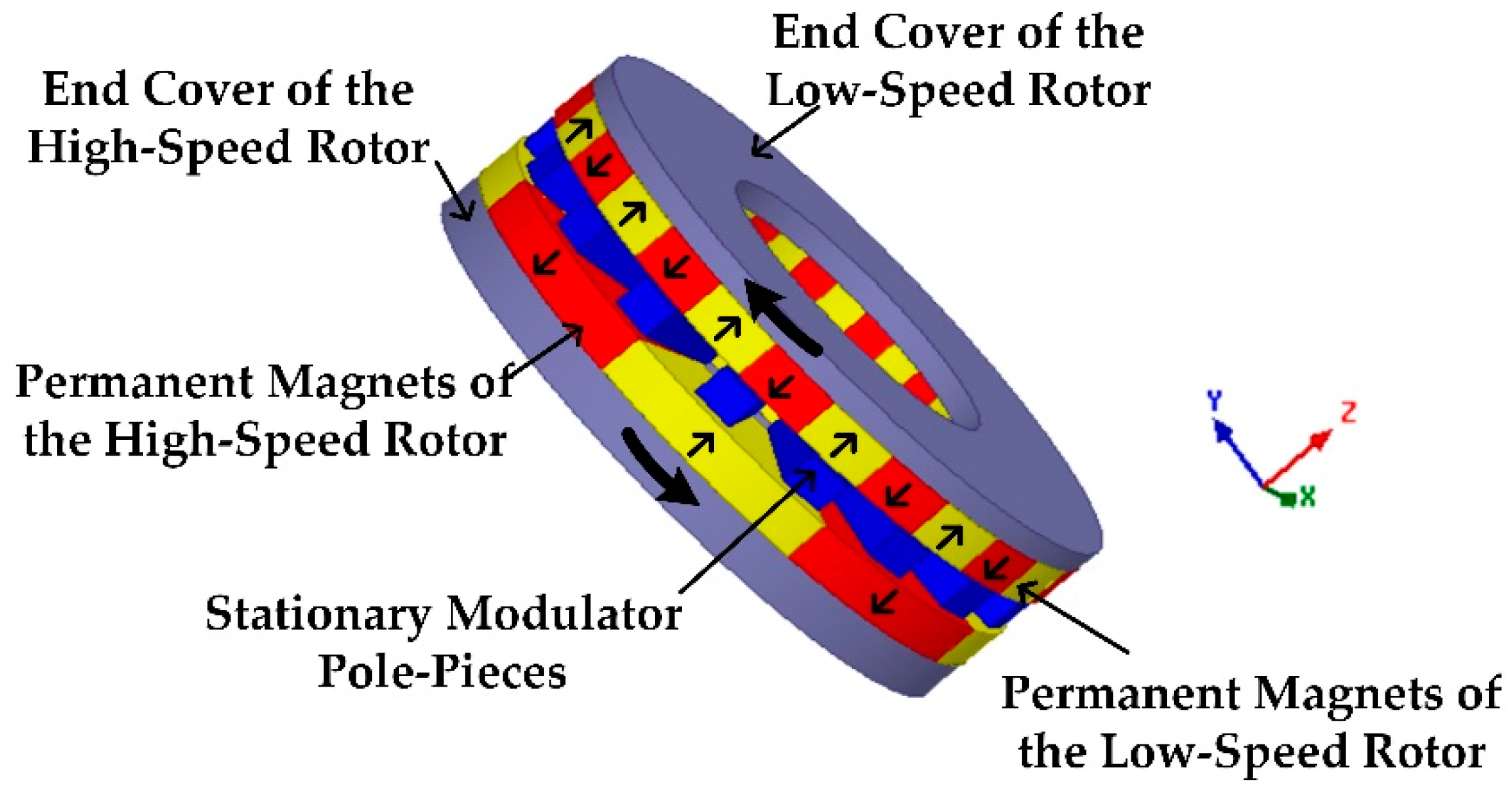
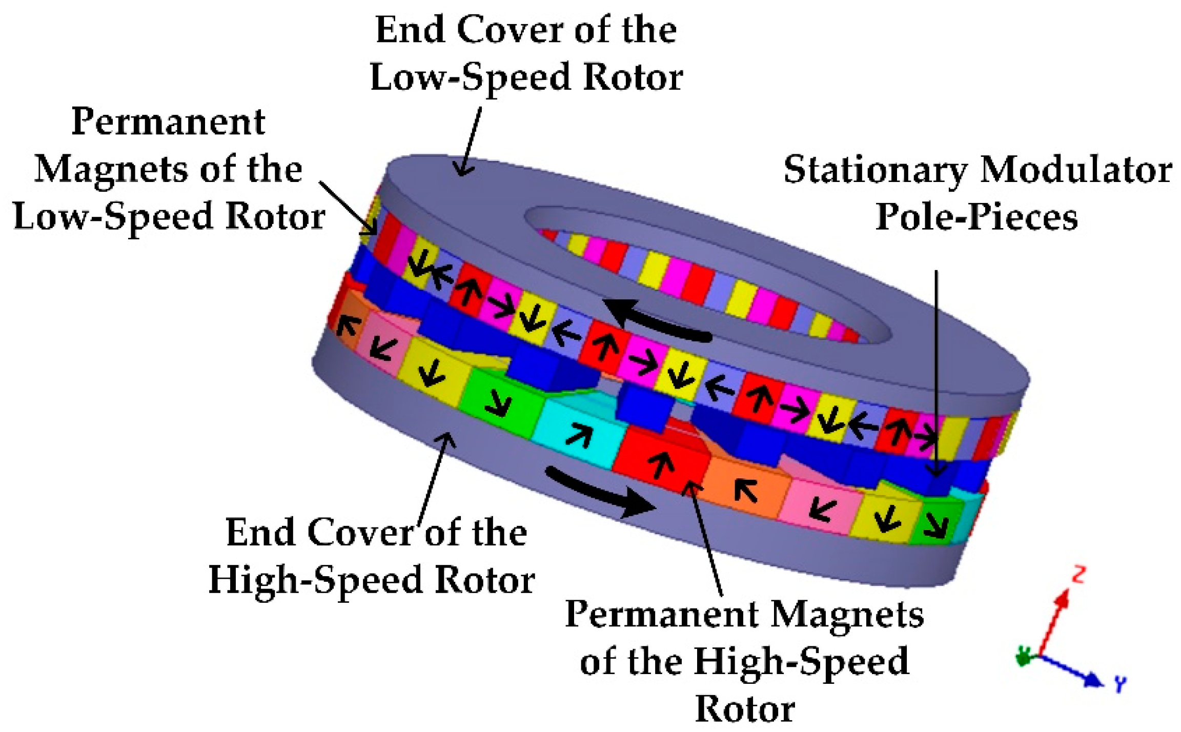
In this paper, in order to study the contribution of each harmonic to the output torque and axial torque of the HAMG in depth, torque and axial force calculation formulas are proposed based on the air-gap flux densities. Because the air-gap flux densities at different radii of the HAMG are not the same, two simplified torque and axial force calculation formulas are proposed and compared. The influence of eight dimensional parameters on the torque capability of the HAMG is studied by the 3D finite element method (FEM). Meanwhile, in order to maximize the output torque density of the HAMG, an optimization is carried out with the aid of the Maxwell software.

2. Topologies of the Halbach Permanent Magnet Array (HAMG)

The topologies of the general AMG and the studied HAMG are shown in Figure 1 and Figure 2, respectively. The difference of the HAMG and the general AMG lies in the magnetization orientations of permanent magnet (PM) pieces. The PMs of the general AMG are axially magnetized, while the HAMG has different orientations of PM pieces. It is well known that Halbach PM arrays hold the attractive features of sinusoidal flux density distribution in the air gap, strong field intensity and good self-shielding magnetization. Therefore, the HAMG is characterized by high stall torque, low torque ripples and iron losses compared with the general AMG.
The HAMG is composed of three parts, namely, the high-speed rotor, the low-speed rotor, and the stationary modulator ring sandwiched between the two rotors. The stationary modulator ring takes charge of modulating the magnetic field in two air gaps beside it. Halbach PM arrays, which are capable of augmenting the magnetic flux in the air gap while suppressing that in the end cover, are adopted for both the two rotors of the studied HAMG. Thus, the two end covers of the HAMG could be made of non-magnetic material instead of iron.
The numbers of PM pole-pairs on the high-speed rotor and the low-speed rotor are, respectively, 4 and 13, resulting a theoretical gear ratio of 3.25, and the number of the modulator pieces is 17. There are 3 PM pieces composing each pole for the high-speed rotor, and 2 PM pieces per pole for the low-speed rotor. Rectangular shaped modulator pole-pieces are adopted for convenient lamination process. Table 1 gives the key dimensional parameters and their initial values for the HAMG.

3. Formulas for Calculating Torque and Axial Force of the Axial Magnetic Gear with Halbach Permanent Magnet Array (HAMG)

The interaction of the space harmonics is the reason for the torque production. It could be shown that the number of pole-pairs in the air-gap flux density produced by either the high-speed or low-speed rotor PMs, is given by,
p m , k = | m p + k n s |
m = 1 , 3 , 5 , ,
k = 0 , ± 1 , ± 2 , ± 3 , , ±
where p is the number of pole-pairs on PM rotor, and ns is the number of the ferromagnetic modulator pole-pieces.
The air-gap flux density of the HAMG includes not only the radial component, the tangential component, but also the axial component. The axial flux density is the most important component of the air-gap flux density, which has the greatest influence on the torque capability of the HAMG. The tangential flux density also has some effect on the torque capability of the HAMG. However, the torque capability of the HAMG is independent of the radial flux density.
The torque and axial force of the HAMG are calculated by the Maxwell stress tensor based on the air-gap flux density distribution,
T = ( R out 2 R in 2 ) 2 μ 0 R in R out 0 2 π B z ( z , r , θ ) B θ ( z , r , θ ) d θ d r
F = ( R out R in ) 2 μ 0 R in R out 0 2 π ( B z 2 ( z , r , θ ) B θ 2 ( z , r , θ ) ) d θ d r
where μ 0 is the vacuum permeability, B z ( z , r , θ ) is the axial flux density and B θ ( z , r , θ ) is the tangential flux density. The air-gap flux densities at different radii are not the same. There is no way to superimpose 0 2 π B z ( z , r , θ ) B θ ( z , r , θ ) d θ and 0 2 π ( B z 2 ( z , r , θ ) B θ 2 ( z , r , θ ) ) d θ at all radii of the air gap, respectively. Therefore, two simplified torque and axial force calculation methods are proposed to calculate the torque and axial force of the HAMG.
The first simplified torque and axial force calculation method is to replace the air-gap flux densities at different radii with the air-gap flux density at the mean radius Rm, where Rm = (Rin + Rout)/2. Therefore, the formulas for the torque and axial force of the HAMG by the first simplified method could be converted as,
T = ( R out 2 R in 2 ) R m 2 μ 0 0 2 π B z ( z , R m , θ ) B θ ( z , R m , θ ) d θ
F = ( R out R in ) R m 2 μ 0 0 2 π ( B z 2 ( z , R m , θ ) B θ 2 ( z , R m , θ ) ) d θ
The expressions of the axial flux density B z ( z , r , θ ) and the tangential flux density B θ ( z , r , θ ) are as follows,
B z ( z , r , θ ) = n = 1 , 2 , 3 + b z n ( z , r ) cos ( n θ φ z n )
B θ ( z , r , θ ) = n = 1 , 2 , 3 + b θ n ( z , r ) cos ( n θ φ θ n )
where b z n and b θ n are the magnitude of Fourier coefficients, φ z n and φ θ n are the initial angles of the axial and tangential flux density distribution. The expressions of the axial flux density B z ( z , R m , θ ) and the tangential flux density B θ ( z , R m , θ ) at the mean radius Rm are as follows,
B z ( z , R m , θ ) = n = 1 , 2 , 3 + b z n ( z , R m ) cos ( n θ φ z n )
B θ ( z , R m , θ ) = n = 1 , 2 , 3 + b θ n ( z , R m ) cos ( n θ φ θ n )
Substituting Equations (8) and (9) into Equations (4) and (5), respectively. Equations (4) and (5) could be transformed as,
T = π ( R out 2 R in 2 ) R m 2 μ 0 n = 1 , 2 , 3 + b z n ( z , R m ) b θ n ( z , R m ) cos ( φ z n φ θ n )
F = π ( R out R in ) R m 2 μ 0 n = 1 , 2 , 3 + [ ( b z n ( z , R m ) ) 2 ( b θ n ( z , R m ) ) 2 ]
It can be found that only the interaction between the axial and tangential flux density components with the same pole-pair number could contribute to the torque and axial force. From (10) and (11), it can be found that the amplitudes of the axial and tangential flux densities of nth-order harmonic at the mean radius as well as their phase difference are critical to the torque production. However, the axial force of the HAMG is only related to the squared difference of amplitudes of the axial and tangential flux densities of nth-order harmonic at the mean radius.
The first simplified torque and axial force calculation method only consider the air-gap flux density at the mean radius, but do not consider that the air-gap flux densities at different radii of the HAMG are not the same. Moreover, the air-gap flux densities near the inner and outer radius are significantly reduced because of flux leakage. Therefore, a second simplified torque and axial force calculation method is proposed to calculate the torque and axial force of the HAMG.
Firstly, the air-gap flux densities at different radii in the air gap adjacent to the low-speed rotor (LG) of the HAMG are studied. The 13th order harmonic contribution to output torque is much larger than other harmonics. The inner radius of the air gap is 40 mm and the outer radius of the air gap is 70 mm. The air gap is divided into 30 parts according to the radius and each one is 1 mm. Draw circles at different radii, obtain the air-gap flux densities at different radii, perform the fast Fourier transformation (FFT) on the air-gap flux densities at different radii and obtain the amplitudes of the axial and tangential flux densities of 13th-order harmonic as well as their phase differences at different radii. Table 2 lists the amplitudes and their phase differences of the axial and tangential flux densities of 13th-order harmonics at different radii in the LG of the HAMG, respectively.
Table 2 shows that the amplitudes of the axial and tangential flux densities of 13th-order harmonics as well as their differences at different radii vary from 0.830 T to 1.41 T, 0.374 T to 0.494 T and 43.0° to 72.7°, respectively.
For the amplitude of the axial flux density of 13th-order harmonic b z 13 , the amplitude of the tangential flux density of 13th-order harmonic b θ 13 and the cosine value of their phase difference of the axial and tangential flux densities of 13th-order harmonic cos ( φ z 13 φ θ 13 ) , the impact of b z 13 on the output torque and axial force of the HAMG is greater than b θ 13 and cos ( φ z 13 φ θ 13 ) 
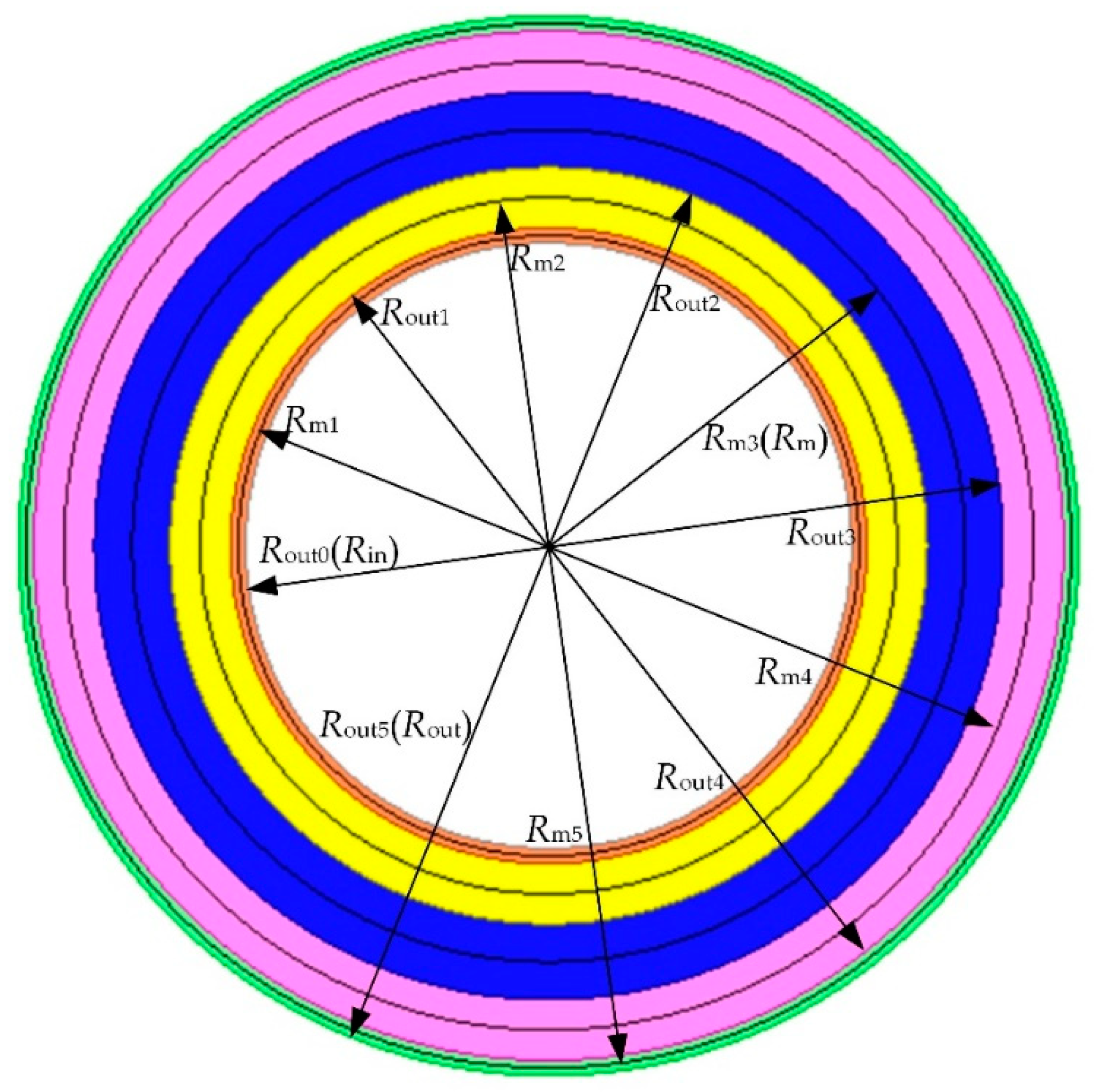
. Therefore, the second simplified calculation method for calculating the torque and axial force of the HAMG is to divide the LG into five parts according to the variation rule of b z 13 at different radii, as shown in Figure 3. Each color represents a part of the LG. The torque and axial force generated by the five parts are superposed to be the torque and axial force generated by the entire HAMG, respectively. The 1st part is from Rout0 = 40 mm to Rout1 = 42 mm, the 2nd part is from Rout1 = 42 mm to Rout2 = 50 mm, the 3rd part is from Rout2 = 50 mm to Rout3 = 60 mm, the 4th part is from Rout3 = 60 mm to Rout4 = 68 mm and the 5th part is from Rout4 = 68 mm to Rout5 = 70 mm.
According to Equations (2) and (3), the expressions of the torque and axial force generated by the ith (i = 1, 2, 3, 4, 5) part are as follows,
T i = ( R out i 2 R out i 1 2 ) 2 μ 0 R out i 1 R out i 0 2 π B z ( z , r , θ ) B θ ( z , r , θ ) d θ d r
F i = ( R out i R out i 1 ) 2 μ 0 R out i 1 R out i 0 2 π ( B z 2 ( z , r , θ ) B θ 2 ( z , r , θ ) ) d θ d r
The air-gap flux densities at different radii of the ith part are replaced by the air-gap flux density at the mean radius Rmi of the ith part, where Rmi = (Routi + Routi−1)/2. Therefore, the expressions of the torque and axial force generated by the ith part could be converted as,
T i = ( R out i 2 R out i 1 2 ) R m i 2 μ 0 0 2 π B z ( z , R m i , θ ) B θ ( z , R m i , θ ) d θ
F i = ( R out i R out i 1 ) R m i 2 μ 0 0 2 π ( B z 2 ( z , R m i , θ ) B θ 2 ( z , R m i , θ ) ) d θ
The expressions of the axial and tangential flux densities at the mean radius Rmi of the ith part are as follows,
B z ( z , R m i , θ ) = n = 1 , 2 , 3 + b z n ( z , R m i ) cos ( n θ φ z n )
B θ ( z , R m i , θ ) = n = 1 , 2 , 3 + b θ n ( z , R m i ) cos ( n θ φ θ n )
Substituting Equations (16) and (17) into Equations (14) and (15), Equations (14) and (15) could be transformed as,
T i = π ( R out i 2 R out i 1 2 ) R m i 2 μ 0 n = 1 , 2 , 3 + b z n ( z , R m i ) b θ n ( z , R m i ) cos ( φ z n φ θ n )
F i = π ( R out i R out i 1 ) R m i 2 μ 0 n = 1 , 2 , 3 + [ ( b z n ( z , R m i ) ) 2 ( b θ n ( z , R m i ) ) 2 ]
Table 3 lists the amplitudes and their phase differences of the axial and tangential flux densities of dominating harmonics at the radii of Rm1, Rm2, Rm3, Rm4 and Rm5 in the HAMG, respectively.
Table 4 lists the torque generated by 4th- and 13th-order harmonics at the radius of Rm in the HAMG calculated by the first simplified torque calculation method. Table 4 lists the torque generated by 4th- and 13th-order harmonics at the radii of Rm1, Rm2, Rm3, Rm4 and Rm5 in the HAMG calculated by the second simplified torque calculation method, respectively. In order to make the results more accurate, Table 4 also lists the total torque generated by other harmonics except for 4th- and 13th-order harmonics.
It can be seen from Table 4 that the torque generated by 4th-order harmonic is much larger than that of other harmonics in the air gap adjacent to the high-speed rotor (HG), while the torque generated by 13th-order harmonic is much greater than that of other harmonics in the LG. The output torque of the HAMG calculated by the 3D FEM is 54.7 Nm. The output torque of the HAMG calculated by the first simplified torque calculation method is 61.1 Nm, which has 12% increase over the HAMG calculated by the 3D FEM. The output torque of the HAMG calculated by the second simplified torque calculation method is 55.8 Nm, which is 2.0% larger than that obtained by the 3D FEM.
Table 5 lists the axial force generated by 4th- and 13th-order harmonics at the radius of Rm in the HAMG by the first simplified axial force calculation method. Table 5 lists the axial force generated by 4th- and 13th-order harmonics at the radii of Rm1, Rm2, Rm3, Rm4 and Rm5 in the HAMG calculated by the second simplified axial force calculation method, respectively. As with the torque calculation, Table 5 also lists the total axial force generated by other harmonics except for the 4th- and 13th-order harmonics.
The axial force on the low-speed rotor of the HAMG obtained by the 3D FEM is 2750 N. The axial force on the low-speed rotor of the HAMG obtained by the first simplified axial force calculation method is 3006 N, which has a 9.3% increase over the HAMG by the 3D FEM. The axial force on the low-speed rotor of the HAMG obtained by the second simplified axial force calculation method is 2728 N, which is 0.80% smaller than that obtained by the 3D FEM.
The air-gap flux densities of the HAMG at different radii are not the same and the air-gap flux densities near the inner and outer radius are significantly reduced due to flux leakage, which may explain why the output torque and axial force of the HAMG obtained by the first simplified calculation method are greater than those calculated by the 3D FEM. The output torque and axial force of the HAMG calculated by the second simplified calculation method are very close to those calculated by the 3D FEM. Therefore, the accuracy of the second simplified calculation method is much higher than the first simplified calculation method. Of course, the finer the air gap is divided, the closer the final calculated torque and axial force of the HAMG are to the actual values of torque and axial force of the HAMG. However, the finer the air gap is divided, the greater the workload is. Therefore, it is reasonable to divide the air gap into five parts.

4. Parametric Analysis of the HAMG

There are various dimensional parameters indicated in Figure 4 affecting the torque capability of the HAMG, including the axial thicknesses on the high-speed rotor Th and on the low-speed rotor Tl, the inner radius Rin, the thickness of the rectangular shape modulation pieces Tm, the length Lm and width Wm of the rectangular shape modulation pieces, the mechanical angle of each axially magnetized PMs on the high-speed rotor θh and that on the low-speed rotor θl. In order to analyze the influence of each individual parameter, when one parameter is changed, other parameters are kept with the initial values shown in Table 1. The influence of each parameter on the output torque and output torque density is illustrated in detail in the following section.

4.1. The Influence of the Axial PMs Thickness of the Two Rotors

Figure 5a,b show the curves of the output torque and output torque density versus Th and Tl, respectively. It can be seen that the output torque will increase with the growth of Th and Tl, but the rate of increase is decreasing gradually. As a result, it is clear that increasing the axial thickness of PMs does not always help to increase the output torque density. This is because the magnetic field of the HAMG may gradually saturate with the growth of the axial thickness of PMs, which means the growth rate of the magnetic field in air gap is lower than that of the PM thicknesses after magnetic field saturation. As could be seen from Figure 5, the output torque density firstly increases with the growth of Th and Tl before saturation and then deceases as saturation occurs. Figure 5a shows that the output torque density achieves the maximum value when Th is approximately 21 mm for the HAMG studied, while the optimal value of Tl is approximately 11 mm as shown in Figure 5b.

4.2. The Influence of the Size of the Rectangular Shape Modulation Pieces

Figure 6 shows the variation of the output torque and output torque density with the axial thickness of the rectangular shape modulation pieces Tm. It is obvious that the trend of the two curves is similar. Although a 4 mm thick rectangular shape modulation pieces may help to achieve the highest torque density, the mechanical stiffness of the modulator ring must be taken into account in practice. Tm is designed as 8 mm in the studied case to guarantee mechanical stiffness.
When Lm and Wm are varied, the volume of the HAMG remains the same. Therefore, the trend of the curves of the output torque and output torque density will be completely the same as these two parameters are changed. Therefore, only the output torque density is considered for these two parametric analysis.
Figure 7 shows the curves of the output torque density versus Lm and Wm. As can be found from Figure 7a, the output torque density may increase with the growth of Lm. As shown in Figure 7b, Wm is better to be designed as 10.5 mm to achieve a maximum output torque density.

4.3. The Influence of the Inner Radius

Because the outer radius Rout of the HAMG is constant, the increase of Rin inevitably leads to a reduction of the amount of PMs, which will surely reduce the output torque. The output torque density could not be used as a criterion for indicating the torque capability of the HAMG since the volume of the HAMG does not change with Rin. The trend of the output torque density curve will be as same as that of the output torque. The effective torque density, which is a ratio of the output torque to the effective volume of the HAMG, is proposed as a new indicator. The effective volume of the HAMG is just the volume of solid part.
The influence of Rin on the output torque and the effective torque density is illustrated in Figure 8. The output torque significantly decreases as Rin increases. A 40 mm inner radius is chosen as the result of overall consideration of the effective torque density as well as dimensions of the bearings and shaft.

4.4. The Influences of the Mechanical Angles of Each Axially Magnetized PMs of the Two Rotors

The relationship between the mechanical angle of PMs per pole on the high-speed rotor ωh, the mechanical angle of each axially magnetized PMs on the high-speed rotor θh, and the mechanical angle of PMs magnetized in other directions on the high-speed rotor τh is,
τ h = ω h θ h
The relationship between the mechanical angle of PMs per pole on the low-speed rotor ωl, the mechanical angle of each axially magnetized PMs on the low-speed rotor θl and the mechanical angle of PMs magnetized in other directions on the low-speed rotor τl is,
τ l = ω l θ l
The influences of θh and θl on the output torque density are shown in Figure 9a,b. The output torque density does not always increase with the increases of θh and θl. The values of θh and θl are better to be selected at 17° and 7° to maximize the output torque density.

5. Optimization of the HAMG

After analyzing the effect of individual dimensional parameters on the torque capability of the HAMG, an optimization is carried out with comprehensive consideration of the interactions among all parameters simultaneously. During the optimization process, the parameters Rout, Rin and Tm are fixed as 70 mm, 40 mm and 8 mm, respectively. Maximizing the output torque density is set as the optimization objective.
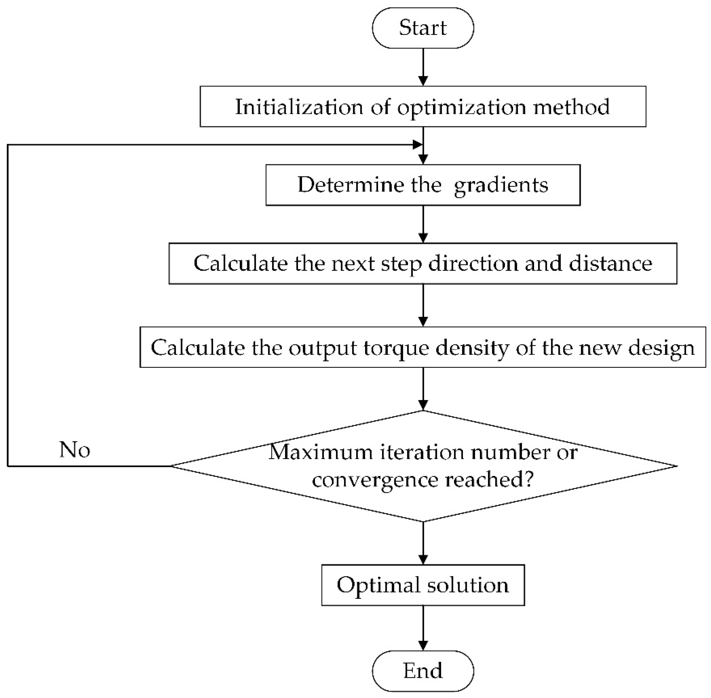
Maxwell software is adopted for the optimization. The optimal solution is found according to the flowchart given in Figure 10. The 3D FEM is used to compute the output torque density in order to enhance the solution accuracy. After more than 400 sets of data calculation, optimization has finally reached convergence. The parametric optimization constraints and results are obtained and listed in Table 6. Moreover, Table 6 presents the comparison between parametric analysis and optimization. The results indicate that a good match is obtained between parametric analysis and optimization results.
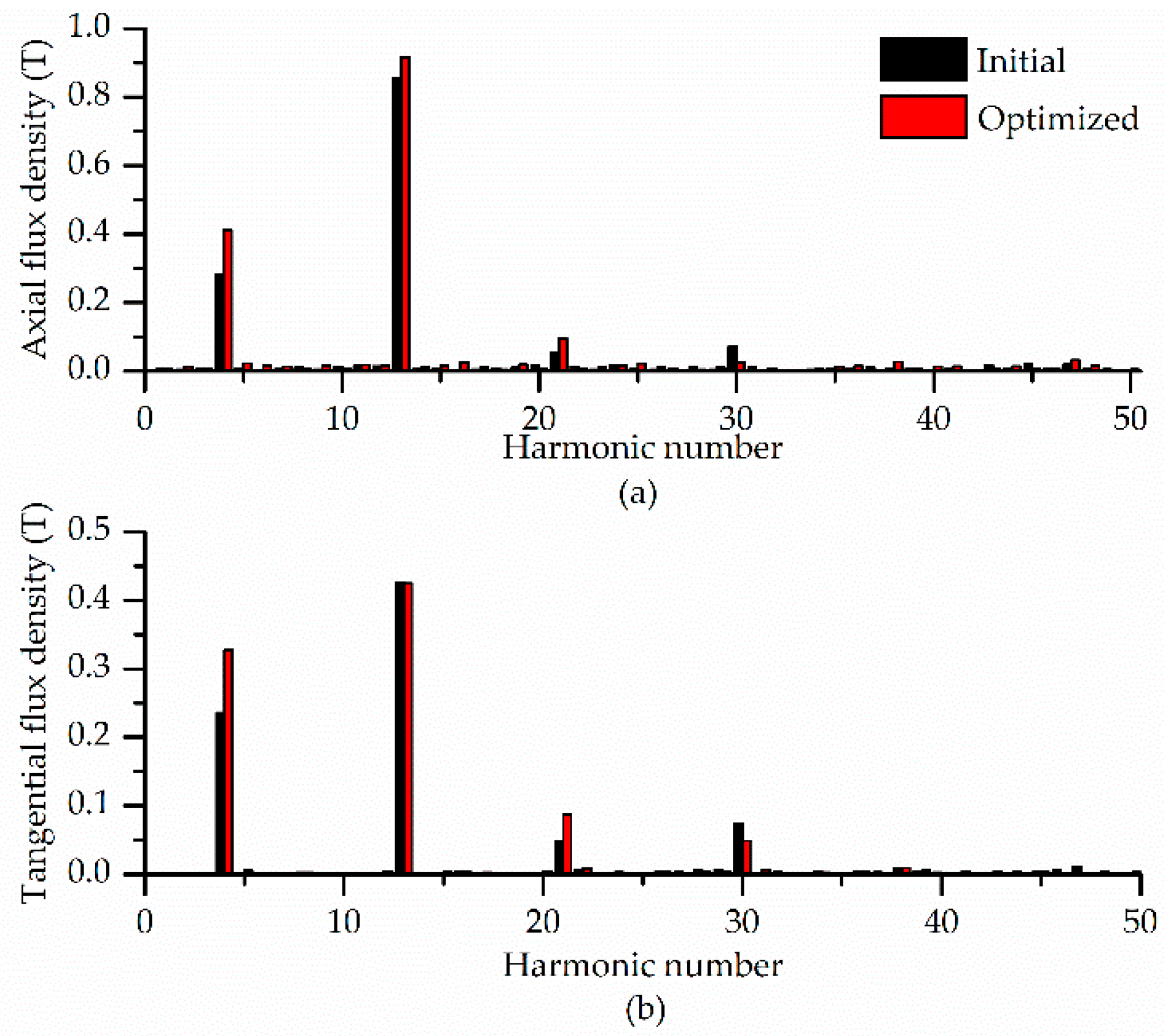
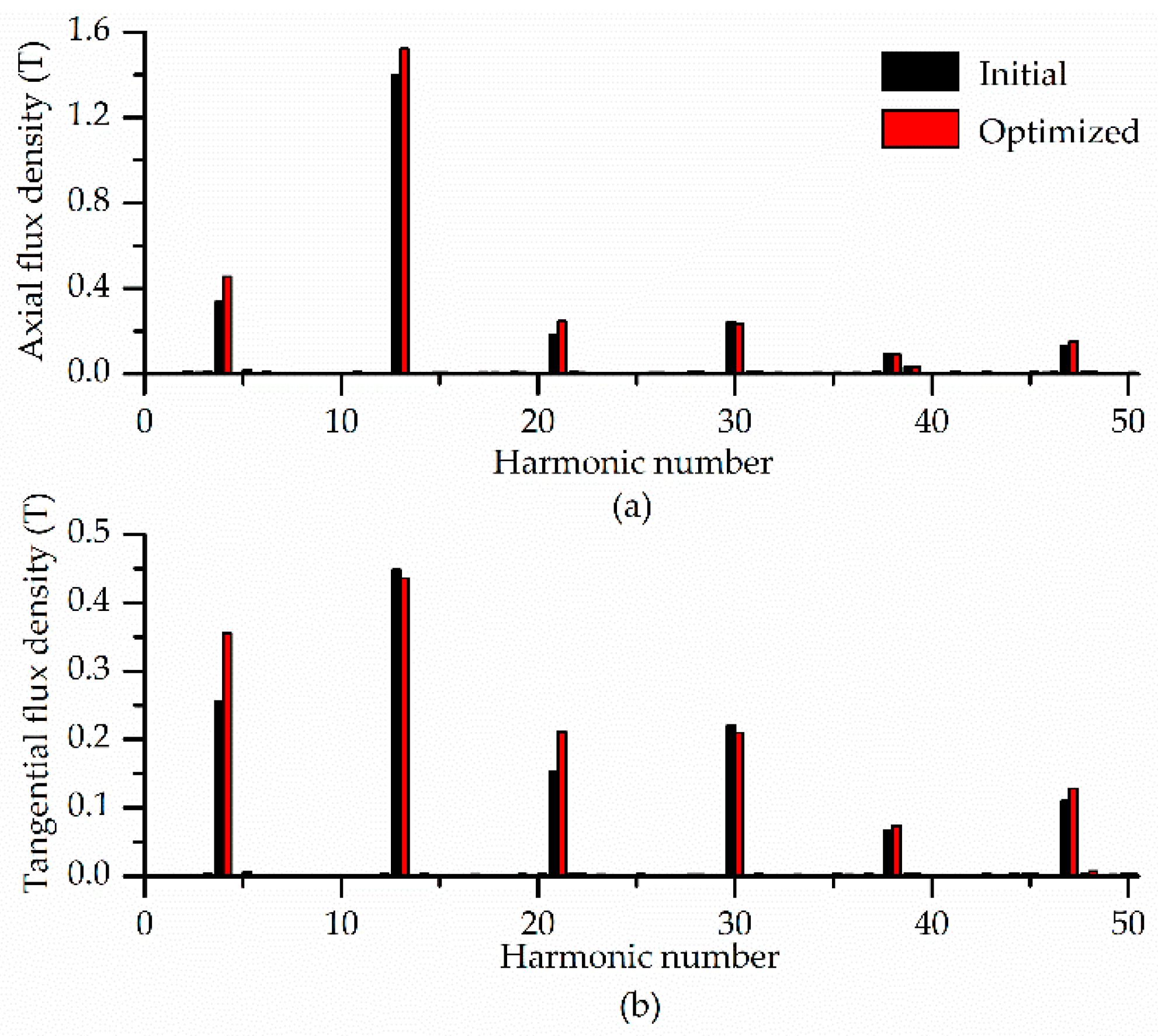
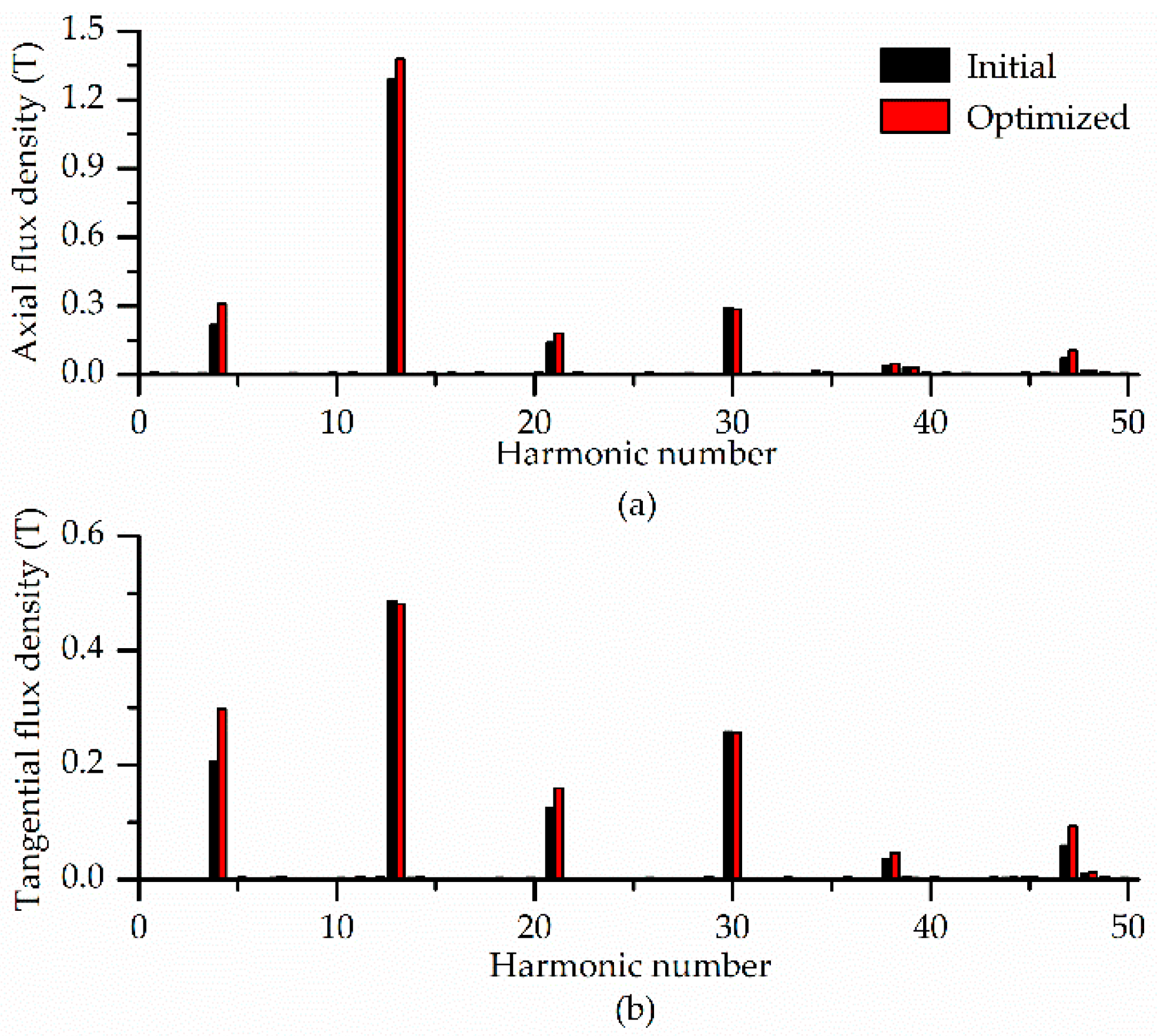
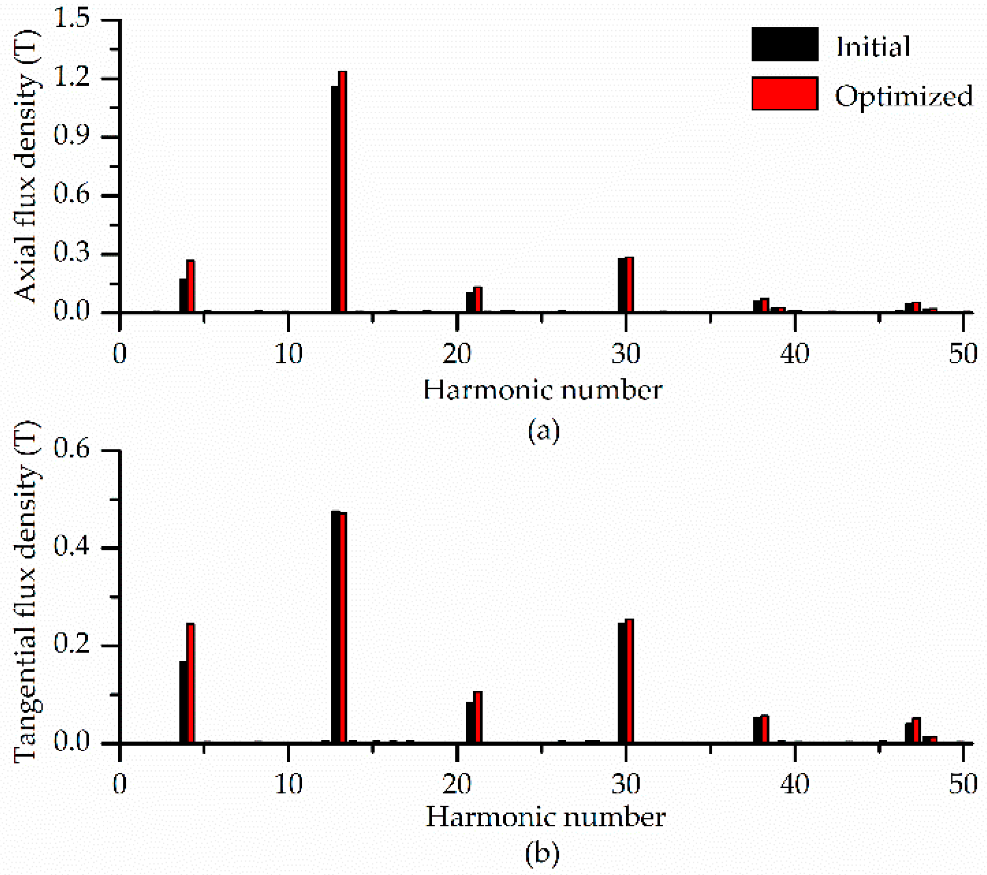
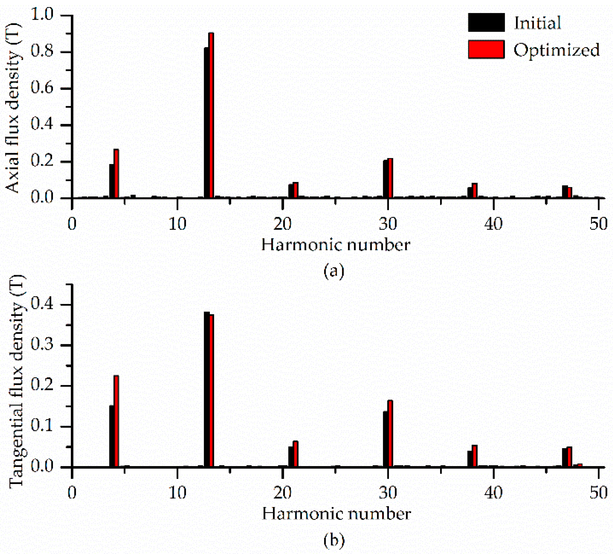
In order to explain the high torque capability of the optimized HAMG in depth, spectrum analysis is presented based on the second simplified torque calculation formulas. Figure 11, Figure 12, Figure 13, Figure 14 and Figure 15 show the FFT analysis of the axial and tangential flux densities at the radii of Rm1, Rm2, Rm3, Rm4 and Rm5 in the LG of the HAMG. It could be shown that the amplitudes of 4th-, 13th-, 21st- and 47th-order harmonics of the axial flux densities and the amplitudes of 4th-, 21st- and 38th-order harmonics of the tangential flux densities at the radii of Rm1, Rm2, Rm3, Rm4 and Rm5 in the LG are all improved by optimization in different degree.
The output torques of the initial and optimized HAMG obtained by the 3D FEM are 54.7 Nm and 82.6 Nm, respectively. The output torque has an increase of 51% by optimization. The initial and optimized output torques obtained by the second simplified calculation method are 55.8 Nm and 84.6 Nm, which are 2.0% and 2.4% larger than the torques obtained by the 3D FEM. Table 7, Table 8, Table 9, Table 10 and Table 11 list the magnitudes of the axial and tangential flux densities of dominating harmonics, their phase differences and generated torque due to the dominant harmonics. The output torque of the HAMG is mainly generated by 13th-order harmonic. Table 7 shows that the algebraic value of b z 13 b θ 13 at the radius of Rm1 is improved from 0.368 to 0.389 by optimization with an increase of 5.7%, while the algebraic value of cos ( φ z 13 φ θ 13 ) is improved from 0.598 to 0.795 with a significant increase of 33%. Table 8 shows that the algebraic value of b z 13 b θ 13 at the radius of Rm2 is improved from 0.623 to 0.664 by optimization with an increase of 6.6%, while the algebraic value of cos ( φ z 13 φ θ 13 ) is improved from 0.615 to 0.837 with a significant increase of 36%. Table 9 shows that the algebraic value of b z 13 b θ 13 at the radius of Rm3 is improved from 0.629 to 0.663 by optimization with an increase of 5.4%, while the algebraic value of cos ( φ z 13 φ θ 13 ) is improved from 0.429 to 0.612 with a significant increase of 43%. Table 10 shows that the algebraic value of b z 13 b θ 13 at the radius of Rm4 is improved from 0.551 to 0.583 by optimization with an increase of 5.8%, while the algebraic value of cos ( φ z 13 φ θ 13 ) is improved from 0.311 to 0.463 with a significant increase of 49%. Table 11 shows that the algebraic value of b z 13 b θ 13 at the radius of Rm5 is improved from 0.313 to 0.339 by optimization with an increase of 8.3%, while the algebraic value of cos ( φ z 13 φ θ 13 ) is improved from 0.350 to 0.521 with a significant increase of 49%. Therefore, the increase in output torque of the HAMG by optimization is mainly caused by the increase of the phase difference of 13th order harmonic. The initial and optimized volumes of the HAMG are 700 cm3 and 885 cm3, respectively. As a result, the output torque density of the HAMG is improved from 78.1 kNm/m3 to 93.3 kNm/m3 by optimization with an increase of 19%.

6. Conclusions

In this paper, torque and axial force calculation formulas are proposed based on the air-gap flux density distribution. Because of the difference of the air-gap flux densities at different radii, two simplified torque and axial force calculation formulas are proposed and compared. The accuracy of the second simplified torque and axial force calculation method is much higher than the first simplified torque and axial force calculation method.
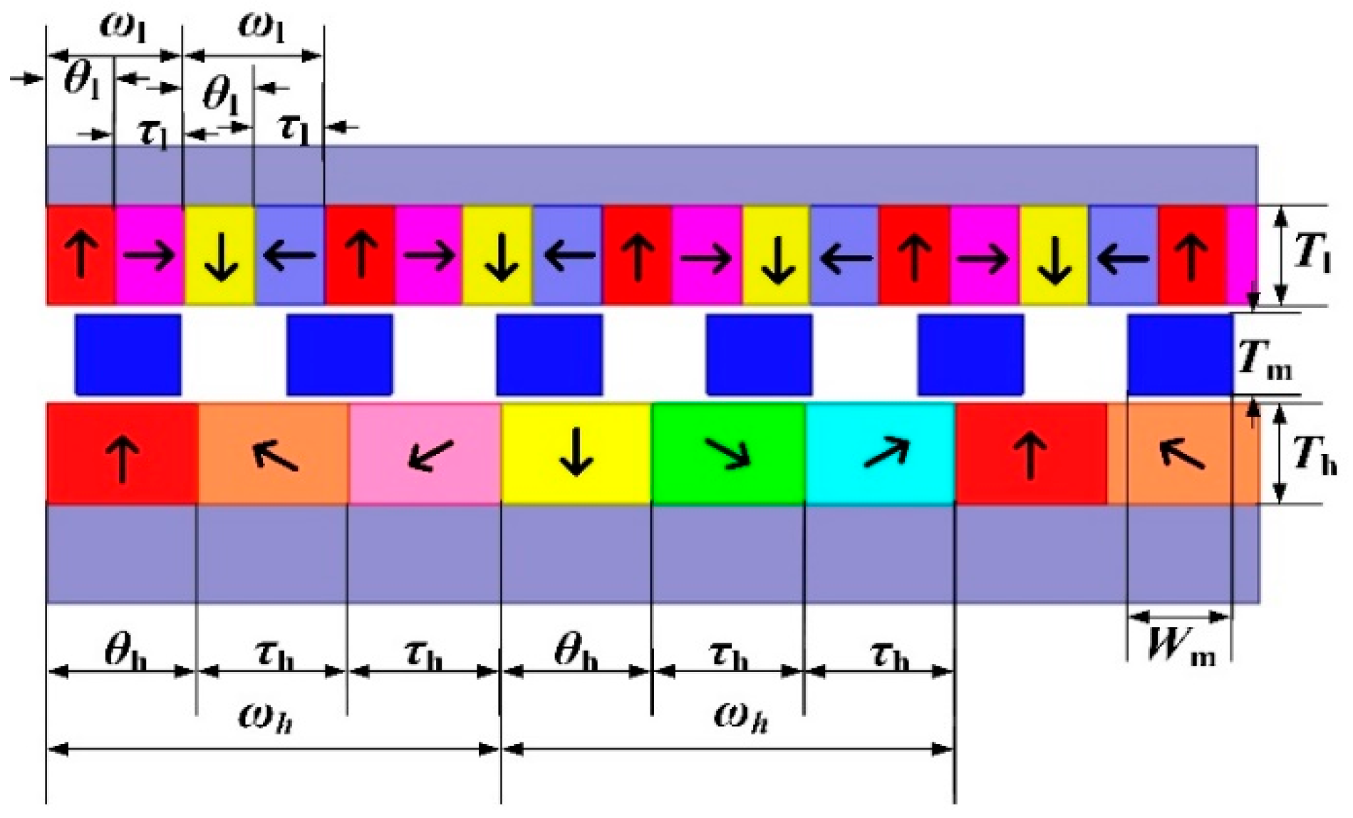
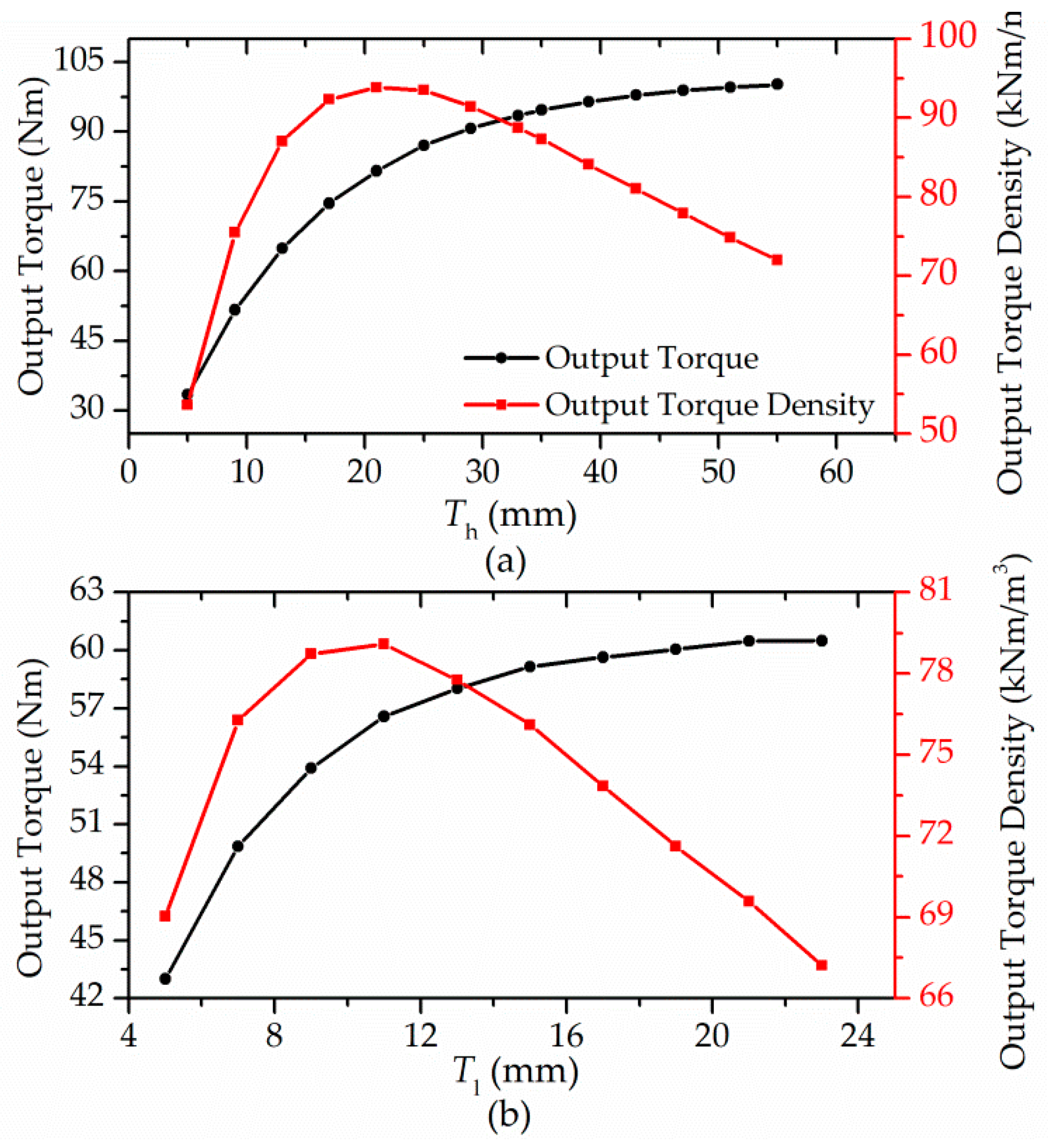
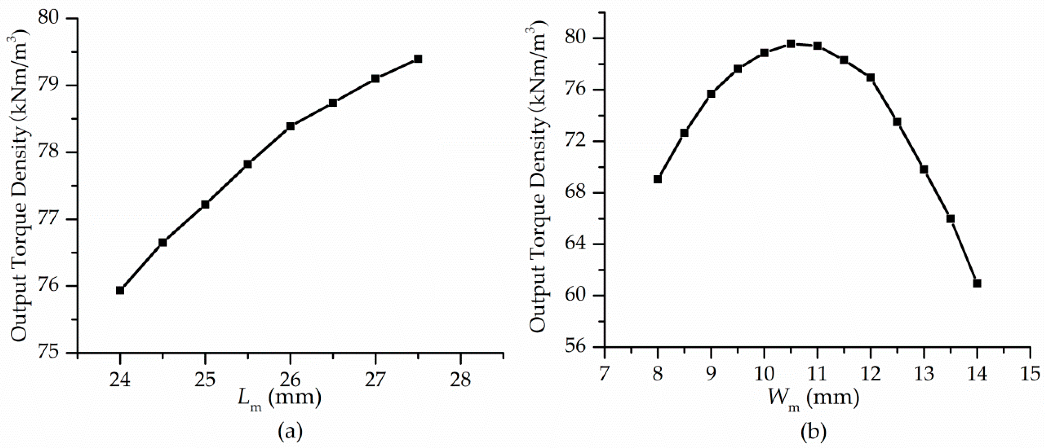
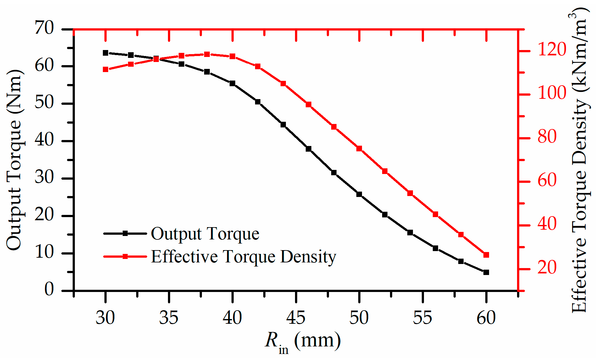
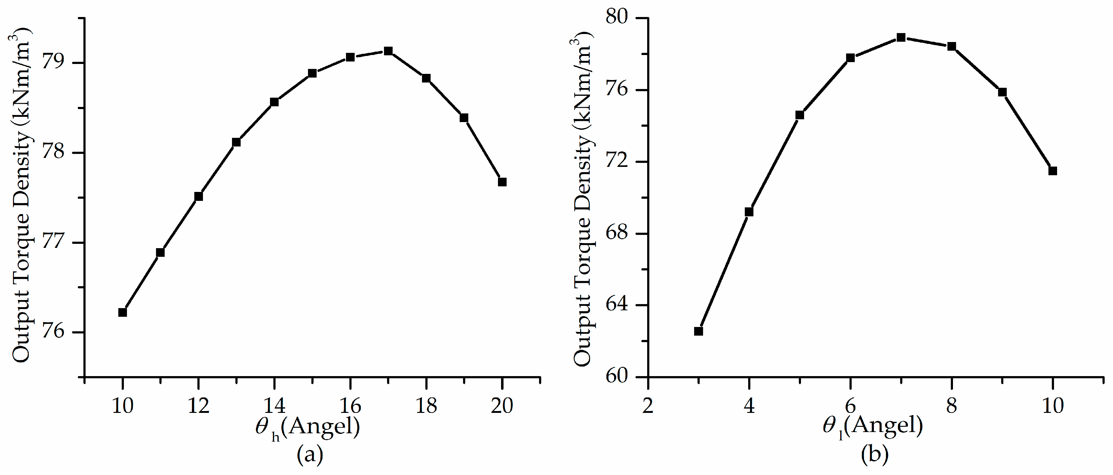
The influence of individual dimensional parameters on the torque capability of the HAMG is investigated. To maximize the output torque density, Maxwell software is used to carry out the optimization with the aid of the 3D FEM. Six parameters, i.e., Th, Tl, Rin, Tm, Wm and θl, play important roles in torque generation of the HAMG. Details are as follows:
  • The output torque density of the HAMG increases first and then decreases as Th, Tl, Tm, Wm and θl increase;
  • The output torque density of the HAMG significantly decreases as Rin increases;
  • Th, Tl and Rin have more significant impacts on the output torque density of the HAMG than others.
Therefore, the amount of PMs is most important for the output torque density of the HAMG.
By carrying out the optimization, the output torque density of the HAMG has an increase of 19%. By spectrum analysis, the increase in output torque by optimization is mainly caused by the phase difference of 13th-order harmonic. The torque and axial force calculation formulas, the influence of individual dimensional parameters on the torque capability and the reason for the increase in output torque by optimization could be applied to the same type of HAMG.

Author Contributions

Conceptualization, F.H. and X.L.; methodology, F.H.; software, Y.Z. and H.C.; validation, Y.Z., H.C. and X.L.; investigation, Y.Z. and X.L.; resources, F.H.; writing—original draft preparation, F.H. and Y.Z.; writing—review and editing, L.X. and Y.Z.; project administration, F.H.

Funding

This research was supported by the National Key R&D Program of China (Grant No. 2018YFB0606000).

Conflicts of Interest

The authors declare no conflict of interest.

References

  1. Atallah, K.; Howe, D. A novel high-performance magnetic gear. IEEE Trans. Magn. 2001, 37, 2844–2846. [Google Scholar] [CrossRef] [Green Version]
  2. Liu, X.; Chau, K.T.; Jiang, J.Z.; Yu, C. Design and analysis of interior-magnet outer-rotor concentric magnetic gears. J. Appl. Phys. 2009, 105, 07F101. [Google Scholar] [CrossRef]
  3. Chau, K.T.; Zhang, D.; Jiang, J.Z.; Liu, C.; Zhang, Y.J. Design of a magnetic-geared outer-rotor permanent magnet brushless motor for electric vehicles. IEEE Trans. Magn. 2007, 43, 2504–2506. [Google Scholar] [CrossRef]
  4. Chau, K.T.; Chan, C.C.; Liu, C. Overview of permanent-magnet brushless drives for electric and hybrid electric vehicles. IEEE Trans. Ind. Electron. 2008, 55, 2246–2257. [Google Scholar] [CrossRef]
  5. Jian, L.; Chau, K.T.; Jiang, J.Z. A magnetic-geared outer-rotor permanent-magnet brushless machine for wind power generation. IEEE Trans. Ind. Appl. 2009, 45, 954–962. [Google Scholar] [CrossRef]
  6. Atallah, K.; Wang, J.; Howe, D. A high-performance linear magnetic gear. J. Appl. Phys. 2005, 97. [Google Scholar] [CrossRef]
  7. Bird, J.; Li, K.; Williams, W.; Kadel, J. A flux focusing cycloidal magnetic gearbox. IEEE Trans. Magn. 2015, 51, 1–4. [Google Scholar]
  8. Rens, J.; Atallah, K.; Calverley, S.D.; Howe, D. A novel magnetic harmonic gear. IEEE Trans. Ind. Appl. 2010, 46, 206–212. [Google Scholar] [CrossRef]
  9. Mezani, S.; Atallah, K.; Howe, D. A high-performance axial-field magnetic gear. J. Appl. Phys. 2006, 99. [Google Scholar] [CrossRef]
  10. Acharya, V.M.; Bird, J.Z.; Calvin, M. A Flux Focusing Axial Magnetic Gear. IEEE Trans. Magn. 2013, 49, 4092–4095. [Google Scholar] [CrossRef]
  11. Tsai, M.; Ku, L. 3-D Printing-Based design of axial flux magnetic gear for high torque density. IEEE Trans. Magn. 2015, 51, 1–4. [Google Scholar] [CrossRef]
  12. Johnson, M.; Gardner, M.C.; Toliyat, H.A. Analysis of axial field magnetic gears with Halbach arrays. Proc. IEEE Int. Elect. Mach. Drives Conf. 2015, 108–114. [Google Scholar]
  13. Matthew, G.; Matthew, J.; Toliyat, H.A. Comparison of surface permanent magnet axial and radial flux coaxial magnetic gears. IEEE Trans. Energy Convers. 2018, 33, 2250–2259. [Google Scholar]
  14. Johnson, M.; Gardner, M.C.; Toliyat, H.A. Design and analysis of an axial flux magnetically geared generator. IEEE Trans. Ind. Appl. 2017, 53, 97–105. [Google Scholar] [CrossRef]
  15. Dong, K.; Yu, H. Study of an axial-flux modulated superconducting magnetic gear. IEEE Trans. Appl. Supercond. 2019, 29. [Google Scholar] [CrossRef]
  16. Zhang, X.; Liu, X.; Chen, Z. A novel dual-flux-modulator coaxial magnetic gear for high torque capability. IEEE Trans. Energy Convers. 2018, 33, 682–691. [Google Scholar] [CrossRef]
  17. Evans, D.J.; Zhu, Z.Q. Influence of design parameters on magnetic gear’s torque capability. Proc. IEEE Int. Elect. Mach. Drives Conf. 2011, 1403–1408. [Google Scholar] [CrossRef]
Figure 1. Topology of the general axial magnetic gear (AMG).
Energies 12 02003 g001
Figure 2. Topology of the axial magnetic gear with Halbach permanent magnet array (HAMG).
Energies 12 02003 g002
Figure 3. Air-gap separation diagram.
Energies 12 02003 g003
Figure 4. The dimensions of the HAMG.
Energies 12 02003 g004
Figure 5. Output torque and output torque density curves versus Th and Tl. (a) Axial thickness of PMs on the high-speed rotor; (b) Axial thickness of PMs on the low-speed rotor.
Energies 12 02003 g005
Figure 6. Output torque and output torque density curves versus Tm.
Energies 12 02003 g006
Figure 7. Output torque density curves versus Lm and Wm. (a) Length of rectangular shape modulation pieces; (b) Width of rectangular shape modulation pieces.
Energies 12 02003 g007
Figure 8. Output torque and effective torque density curves versus Rin.
Energies 12 02003 g008
Figure 9. Output torque density curves versus θh and θl. (a) Mechanical angle of each axially magnetized PMs on the high-speed rotor; (b) Mechanical angle of each axially magnetized PMs on the low-speed rotor.
Energies 12 02003 g009
Figure 10. Procedure with the 3D FEM embedded in the optimization algorithm.
Energies 12 02003 g010
Figure 11. Fast Fourier transformation (FFT) analysis of the axial and tangential flux densities at the radius of Rm1 in the air gap adjacent to the low-speed rotor (LG) of the HAMG. (a) Axial flux density; (b) Tangential flux density.
Energies 12 02003 g011
Figure 12. FFT analysis of the axial and tangential flux densities at the radius of Rm2 in the LG of the HAMG. (a) Axial flux density; (b) Tangential flux density.
Energies 12 02003 g012
Figure 13. FFT analysis of the axial and tangential flux densities at the radius of Rm3 in the LG of the HAMG. (a) Axial flux density; (b) Tangential flux density.
Energies 12 02003 g013
Figure 14. FFT analysis of the axial and tangential flux densities at the radius of Rm4 in the LG of the HAMG. (a) Axial flux density; (b) Tangential flux density.
Energies 12 02003 g014
Figure 15. FFT analysis of the axial and tangential flux densities at the radius of Rm5 in the LG of the HAMG. (a) Axial flux density; (b) Tangential flux density.
Energies 12 02003 g015
Table 1. Key parameters of the HAMG.
DescriptionValue
axial thickness of PMs on the high-speed rotor, Th (mm)10
axial thickness of PMs on the low-speed rotor, Tl (mm)10
axial thickness of end cover on the high-speed rotor (mm)10
axial thickness of end cover on the low-speed rotor (mm)5.5
axial thickness of rectangular shape modulation pieces, Tm (mm)8
inner radius, Rout (mm)40
outer radius, Rin (mm)70
axial thickness of air-gaps (mm)1
length of rectangular shape modulation pieces, Lm (mm)27
width of rectangular shape modulation pieces, Wm (mm)10
mechanical angle of each axially magnetized PMs on the high-speed rotor, θh (°)15
mechanical angle of each axially magnetized PMs on the low-speed rotor, θl (°)6.92
PM materialNdFeB35
material of stationary modulator pole-piecesDW360_50
Table 2. Amplitudes and their phase differences of the axial and tangential flux densities of 13th-order harmonics at different radii.
Radius/mm b z 13 / T b θ 13 / T φ z 13 φ θ 13 / ° Radius/mm b z 13 / T b θ 13 / T φ z 13 φ θ 13 / °
410.8500.43053.3561.280.48966.1
421.260.44143.2571.260.49266.9
431.410.43243.0581.250.49367.9
441.390.43946.3591.250.49468.9
451.400.44548.5601.230.49369.7
461.390.45152.1611.220.49170.5
471.380.45752.6621.200.48671.2
481.370.46154.3631.190.48271.6
491.360.46456.1641.160.48071.9
501.350.46957.9651.130.46772.7
511.340.47659.6661.110.45672.5
521.330.47861.3671.060.43672.3
531.320.48262.2680.9970.41171.3
541.300.48563.4690.8300.37469.5
551.290.49164.6
Table 3. Axial and tangential flux densities at the radii of Rm1, Rm2, Rm3, Rm4 and Rm5 in the HAMG and their phase differences.
Harmonic OrderPhPl
4th13th
b z 4 / T b θ 4 / T φ z 4 φ θ 4 / ° b z 13 / T b θ 13 / T φ z 13 φ θ 13 / °
Rm1HG0.4910.3431160.1590.12185.6
LG0.2790.24182.40.8580.43253.3
Rm2HG0.9080.3511170.1710.15994.6
LG0.3320.25982.11.390.44852.1
Rm3HG0.8490.3111080.08990.080197.4
LG0.2280.19889.61.290.48964.6
Rm4HG0.7470.2731030.0820.069882.3
LG0.1720.16976.91.160.48171.9
Rm5HG0.4510.2231050.1110.0701102
LG0.1690.15183.40.8410.36969.5
Table 4. Torque at different radii by the first or second simplified torque calculation method.
MethodHarmonic OrderTorque/Nm
4th13thOtherSum
The first simplified torque calculation methodRmHG−18.7−0.221−0.124−19.0
LG0.080461.1−0.11261.1
The second simplified torque calculation methodRm1HG−0.6120.01010.0211−0.581
LG0.07011.850.010201.93
Rm2HG−6.08−0.0823−0.141−6.30
LG0.042116.2−0.12216.2
Rm3HG−6.24−0.0812−0.0402−6.36
LG0.031120.4−0.039820.4
Rm4HG−3.680.0611−0.0101−3.63
LG0.53114.00.11114.6
Rm5HG−0.642−0.03980.0198−0.662
LG0.07342.590.06472.73
Table 5. Axial force at different radii by the first or second simplified axial force calculation method.
MethodHarmonic OrderAxial Force/N
4th13thOtherSum
The first simplified axial force calculation methodRmHG12984621364
LG212955303006
The second simplified axial force calculation methodRm1HG12.31.200.90014.4
LG2.2056.6058.8
Rm2HG3274.4018.7350
LG20.379711.6829
Rm3HG4331.3020.7455
LG7985101002
Rm4HG3141.4022.6338
LG1.1071619.9737
Rm5HG26.51431.5
LG0.80097.33.2101
Table 6. Optimal parameters of the HAMG.
ParametersRestrictionsOptimizationParametric Analysis
Th5–55 mm20.9 mm21 mm
Tl5–23 mm11.1 mm11 mm
Lm24–27.5 mm27.5 mm27.5 mm
Wm8–14 mm10.5 mm10.5 mm
θh10–20°16.9 mm17°
θl3–10°6.9 mm
Table 7. Amplitudes, the phase differences and torque due to the air-gap flux density at the radius of Rm1.
Harmonic Order b z n / T b θ n / T φ z n φ θ n / ° Torque/Nm
4thInitial Design0.2820.23582.40.0760
Optimized Design0.4120.32876.90.257
13thInitial Design0.8590.42853.31.85
Optimized Design0.9160.42537.42.60
21stInitial Design0.05300.0470166−0.0200
Optimized Design0.09500.0870124−0.0390
30thInitial Design0.07200.074044.00.0320
Optimized Design0.02600.049010.70.0100
Table 8. Amplitudes, the phase differences and torque due to the air-gap flux density at the radius of Rm2.
Harmonic Order b z n / T b θ n / T φ z n φ θ n / ° Torque/Nm
4thInitial Design0.3260.25682.10.0410
Optimized Design0.4550.35682.60.882
13thInitial Design1.390.44852.116.2
Optimized Design1.520.43633.123.5
21stInitial Design0.1830.15392.6−0.0540
Optimized Design0.2460.21192.3−0.0900
30thInitial Design0.2420.22092.7−0.106
Optimized Design0.2340.21095.2−0.188
Table 9. Amplitudes, phase differences and torque due to the air-gap flux density at the radius of Rm3.
Harmonic Order b z n / T b θ n / T φ z n φ θ n / ° Torque/Nm
4thInitial Design0.2270.20389.60.0250
Optimized Design0.310.29889.70.0410
13thInitial Design1.290.48764.620.4
Optimized Design1.380.48152.230.7
21stInitial Design0.1400.12488.30.0390
Optimized Design0.1800.15989.30.0250
30thInitial Design0.2920.25888.90.107
Optimized Design0.2850.25690.2−0.0230
Table 10. Amplitudes, phase differences and torque due to the air-gap flux density at the radius of Rm4.
Harmonic Order b z n / T b θ n / T φ z n φ θ n / ° Torque/Nm
4thInitial Design0.1720.16576.90.528
Optimized Design0.2690.24479.40.989
13thInitial Design1.160.47571.914.0
Optimized Design1.240.47162.422.1
21stInitial Design0.1000.083091.6−0.0190
Optimized Design0.1330.10684.90.101
30thInitial Design0.2770.24690.1−0.0130
Optimized Design0.2850.25490.9−0.0910
Table 11. Amplitudes, the phase differences and torque due to the air-gap flux density at the radius of Rm5.
Harmonic Order b z n / T b θ n / T φ z n φ θ n / ° Torque/Nm
4thInitial Design0.1740.15183.40.0720
Optimized Design0.2670.22584.20.146
13thInitial Design0.8390.37369.52.61
Optimized Design0.9040.37558.64.20
21stInitial Design0.07400.050076.50.0210
Optimized Design0.08600.064088.00.00500
30thInitial Design0.2050.13786.70.0380
Optimized Design0.2180.16484.00.0890

