Article

Enhanced Threshold Point Calculation Algorithm for Switch Fault Diagnosis in Grid Connected 3-Phase AC–DC PWM Converters

1
Department of Electrical and Computer Engineering, Sungkyunkwan University, 2066, Seobu-ro, Jangan-gu, Suwon-si 16419, Gyeonggi-do, Korea
2
Intelligent Mechatronics Research Center, Korea Electronics Technology Institute (KETI) 388, Songnae-daero, Wonmi-gu, Bucheon-si 14502, Gyeonggi-do, Korea
*
Author to whom correspondence should be addressed.
Energies 2019, 12(10), 1979; https://doi.org/10.3390/en12101979
Submission received: 6 May 2019 / Revised: 20 May 2019 / Accepted: 21 May 2019 / Published: 23 May 2019
(This article belongs to the Special Issue Fault Diagnosis and Fault-Tolerant Control)

Abstract

:
The resilience of systems with alternating current (AC)–direct current (DC) converters has been investigated with the aim of improving switch fault diagnosis. To satisfy this aim, this paper proposes a switch fault diagnosis algorithm for three-phase AC–DC converters. The proposed algorithm operates using the phase current instead of the average current to reduce the calculation time required for fault switch detection. Moreover, a threshold point calculation method is derived using a theoretical analysis, which was lacking in previous research. Using the calculated threshold point, a switch fault diagnosis algorithm is obtained to detect faults independent of the load condition. Using the proposed algorithm, switch faults can be detected within 4 ms, which is the recommended value for uninterruptible power supply (UPS). The theoretical analysis, the operating principle, and the experimental results on a 3-kW grid-tied AC–DC converter test-bed are presented herein, which verify the performance of the proposed algorithm.

1. Introduction

In hybrid grid systems that combine the alternating current (AC) grid and the direct current (DC) grid for compensating the disadvantages of both grids alone, the AC–DC converter connects both AC and DC grids [1]. The most important consideration point for evaluating the reliability of the AC–DC converter is resilience. Resilience is defined as its ability to maintain stable power delivery between grid systems, even during AC–DC converter fault conditions. Until now, the main causes of power electronics equipment failures, such as power semiconductor failure, capacitor temperature stress, gate driver failure, and soldering failures, have been surveyed. According to the results of surveys on installed power electronics equipment in the field, power semiconductor failure makes up a significant percentage, approximately 31% [2,3]. Among these power semiconductor failure results, several characteristics of switch open faults can be observed: (1) detecting switch-open failure is difficult, because observing precipitous variations in a system is difficult; and (2) system performance decreases owing to switch-open failure, thereby increasing the input current total harmonic distortion (THD) and the voltage ripple of the DC link. Therefore, a switch fault detection algorithm is required to improve system resilience.
In this algorithm, the fast switch fault detection is the major factor influencing the improvement of system resilience. The time required to detect a switch fault is defined differently for each application. For example, the time is recommended to be less than 4 ms in the case of uninterruptible power systems (UPS) classified as high-resilience systems [4,5]. Many studies have been conducted with the aim of satisfying this requirement, and the methods therein have been categorized in terms of converter pole voltage and converter phase current. The converter pole voltage method has the disadvantage of using voltage sensors, which are rarely used in grid-tied converters for acquiring information on the switch voltage [6,7]. In previous research using the voltage sensor, the faulty switch was detected by comparing between gate signal and switch voltage. Therefore, in order to detect the switch fault, the voltage sensors were required depending on the number of switches. However, the voltage sensing method has a faster switch fault diagnosis time than the phase current method. The switch fault diagnosis of the phase current method has the advantage of detecting switch faults without using any additional hardware [8,9,10,11,12,13,14,15].
The classical switch fault diagnosis methods using phase current are the Park’s vector approach, the normalized vector method, and the DC current method. These methods use the average phase current, which is changed depending on the switch fault position. These methods require time to obtain the average current, which is calculated by integrating id, iq per one cycle of the grid frequency and more than one cycle for fault diagnosis [16]. Additionally, the average current is used for calculating the parameters of fault diagnosis, which is the fault magnitude, the phase angle, and the normalized vector. Therefore, obtaining superior fault detection time is difficult in classical switch fault diagnosis methods, because the phase current methods require more than 16.6 ms for switch fault diagnosis in the grid-tied condition.
In order to overcome these disadvantages, the diagnosis method using the phase current without calculating the average current has been proposed [17,18,19,20]. However, these previous methods that lack the calculation of the average current have inaccurately determined threshold points, which identify switch-normal and fault conditions using values from experience without any mathematical analysis. In previous studies, under a low threshold point, the possibility of misdiagnosis increases, because it is difficult to distinguish between the varying phase current and the fault current. In the case of high threshold points, the switch fault diagnosis time is extended for reaching the high threshold point. Therefore, in order to obtain the fast fault diagnosis in all load ranges, the threshold point should be theoretically analyzed and applied based on system parameters.
Therefore, in this paper, the switch fault diagnosis algorithm adopting the threshold point calculation method is proposed for overcoming the drawbacks of previous switch fault diagnosis methods using the phase current on a grid-tied AC–DC converter. For improving the fault diagnosis algorithm, the phase current and the current ripple are theoretically analyzed for determining the threshold point. The calculated threshold point is applied, thus the diagnosis algorithm can shorten the switch fault diagnosis time to 4 ms or less, which is the recommended value of UPS. To verify the superiority of the proposed algorithm, previously studied algorithms are analyzed and compared with the proposed algorithm, and the experimental results during the switch fault condition are presented.

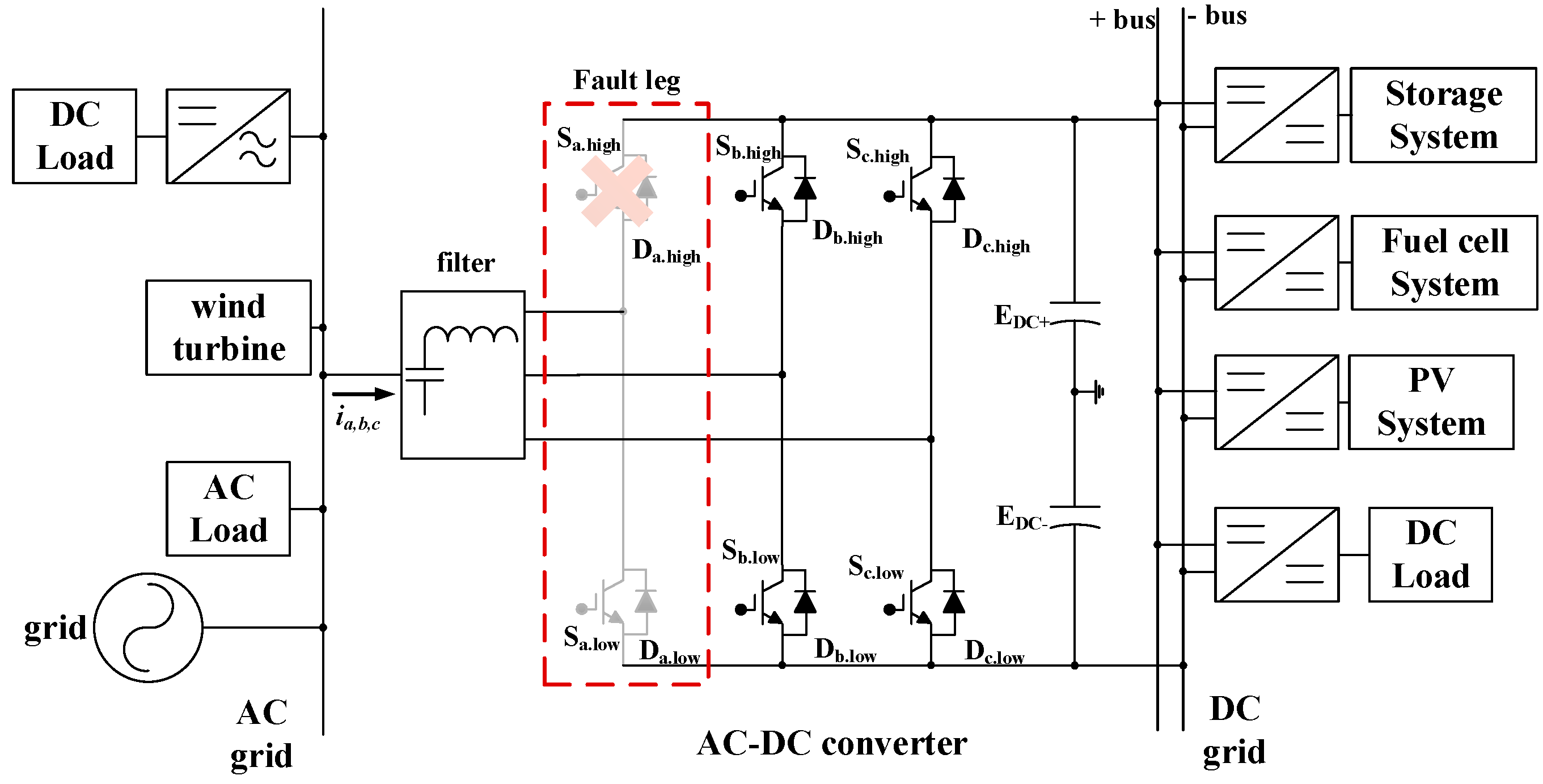
2. Switch Fault of the Grid-Tied AC–DC Converter for Hybrid Grid Systems

Figure 1 presents a hybrid grid system that contains a basic AC–DC converter for power transfer in each grid. In this system, the rapid switch fault diagnosis of the AC–DC converter is required to improve system resilience. In this AC–DC converter application, several studies have been conducted on tolerance operations, which is used to improve system resilience after fault diagnosis [21,22,23]. Among the methods proposed in these previous studies, the exact location of the fault switch is rarely required for tolerance operation; most tolerance operation methods only require the fault leg, which consists of the faulty switch. Therefore, for tolerance operation, the fault diagnosis algorithm must only identify the fault switch leg without considering the fault switch location.
The phase current of the AC–DC converter before and after the switch fault is presented in Figure 2. If the high-side switch of the converter fails, the phase current of the negative side is not controlled, as shown in Figure 2a. In contrast, when the low-side switch fails, the positive current is uncontrolled, as shown in Figure 2c. According to the switch position, the equivalent circuits of the switch fault condition are presented in Figure 2b,d.
When the switch fails, the slope of the phase current on the fault leg is changed by (1). The phase current is decreased until reaching nearly zero after the switch fault [24,25,26]. The characteristics between the normal condition phase current and the fault condition phase current should be identified for progressing the phase current diagnosis algorithm. The magnitude of the phase current changes depending on the grid frequency, and the phase current crosses the zero point periodically without the switch fault condition. Therefore, the average current is used in the switch fault algorithm, because it is difficult to compare characteristics before and after the switch fault. This algorithm uses the difference in the average current between the switch fault section and the normal section for switch fault diagnosis.
d i a d t = ( v a n S E D C + ( 1 S ) E D C ) / L a
where S = 1 if Sa.high or Da.high ON, S = 0 if Sa.low or Da.low ON

3. Operational Principle of Proposed Fault Diagnosis Algorithm

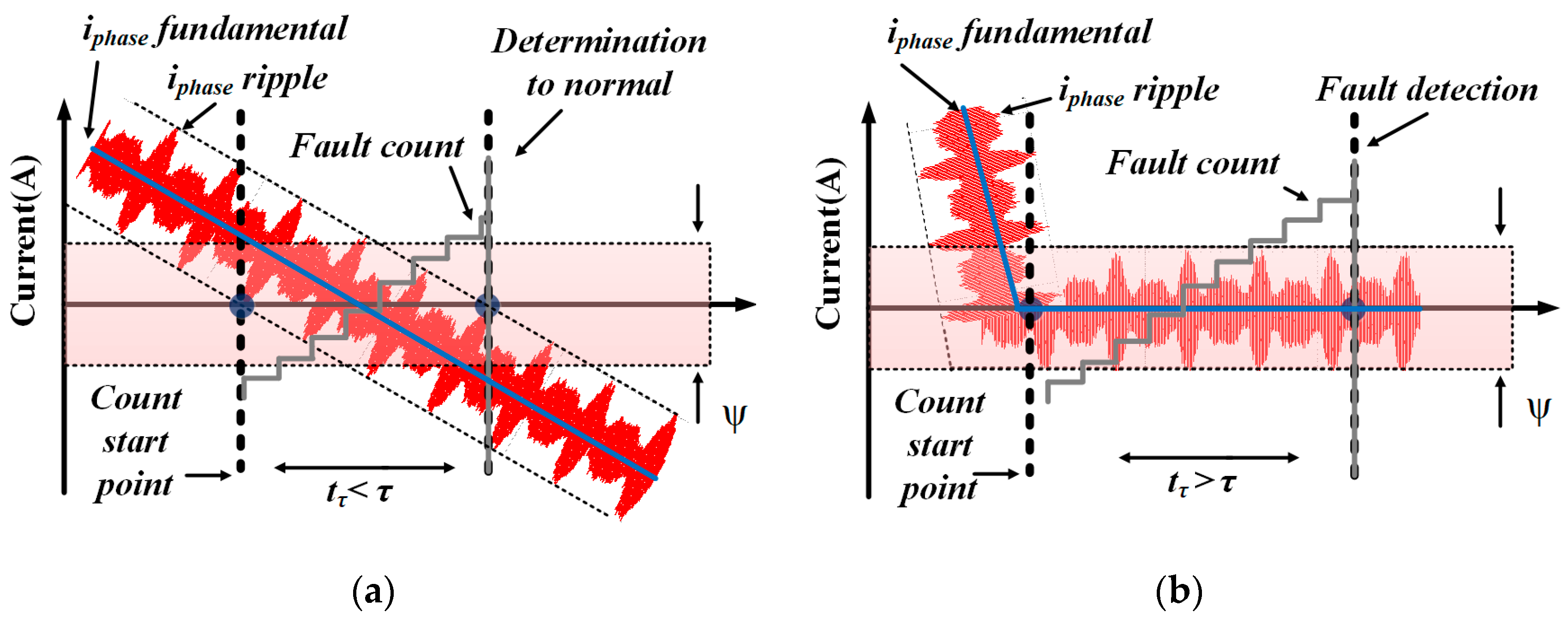
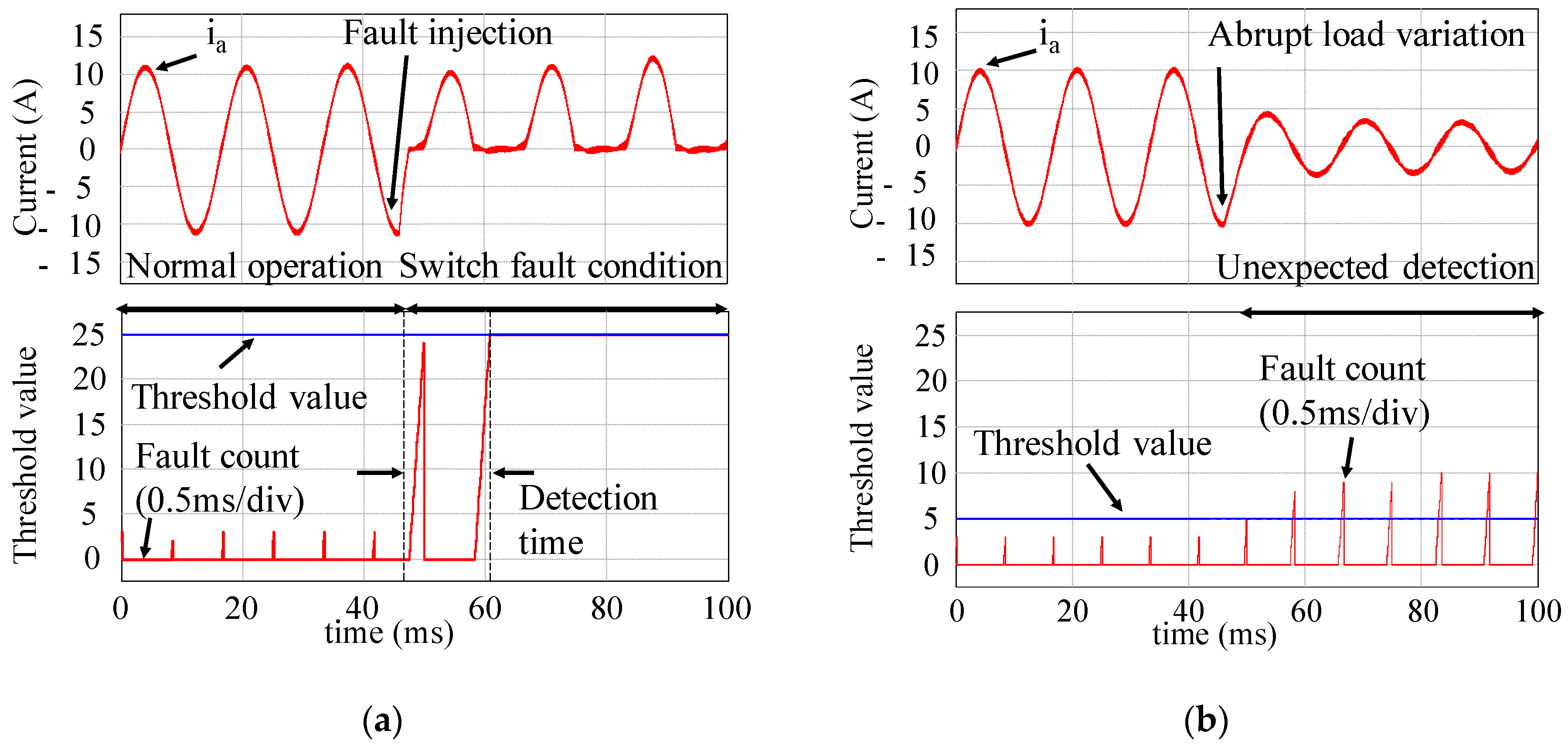
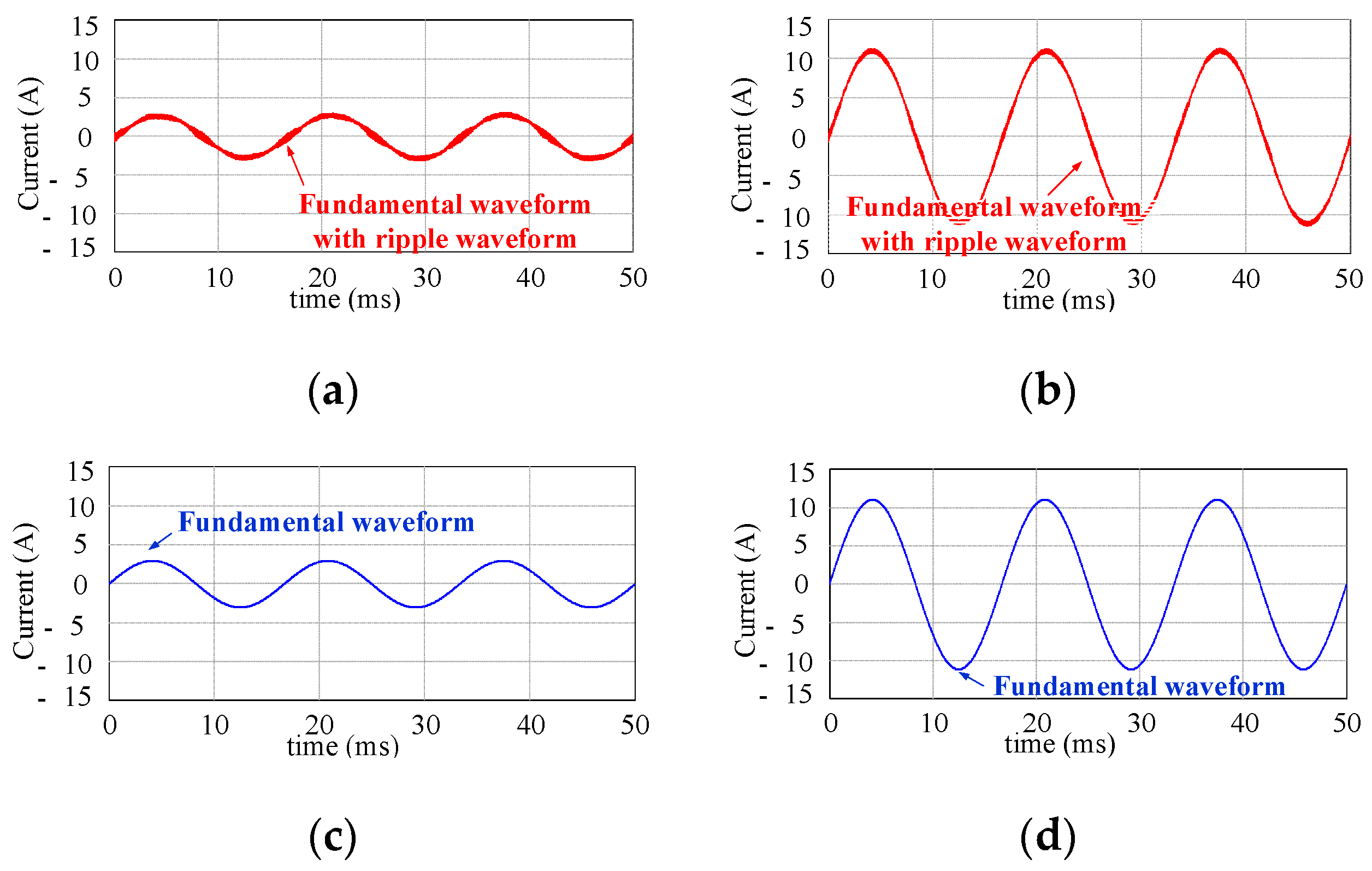
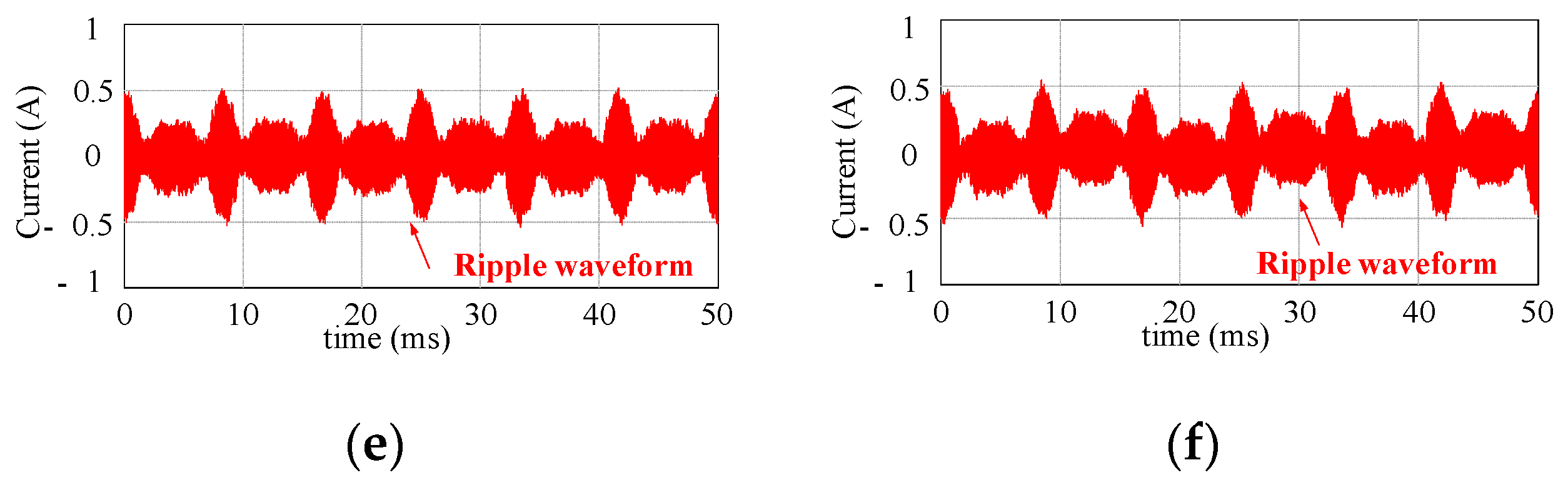
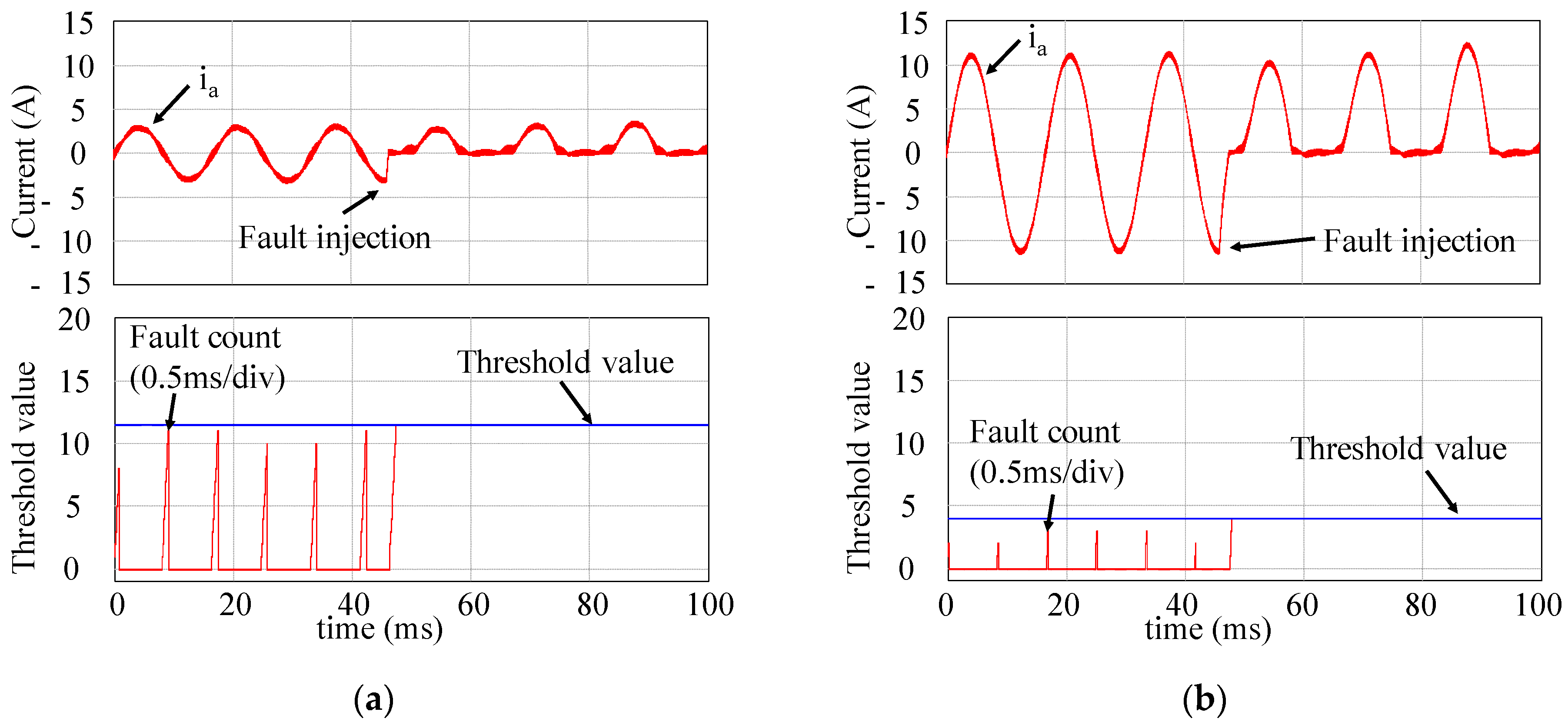
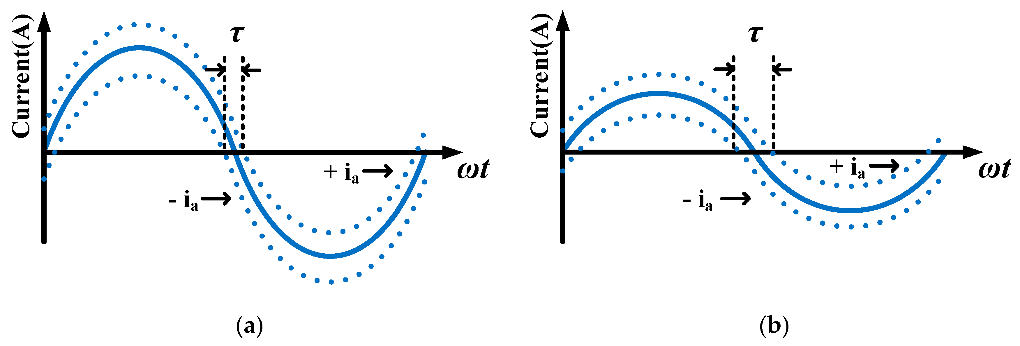
3.1. Limitation of Previous Counting Method

As shown in Figure 2, the phase current reaches zero in the zero crossing of the normal condition and the switch fault condition. Therefore, using this characteristic of the phase current in the switch fault condition, the faulty leg can be detected by obtaining the time difference of the phase current that is nearly zero between the switch normal condition and the switch fault condition, as shown in Figure 3. Under the switch normal condition, the fault counter operates for a short time, as shown in Figure 3a. Under the switch fault condition, as shown in Figure 3b, the fault counter is operated for a longer time compared with the switch normal condition. However, the threshold points for distinguishing between the switch normal condition and the fault condition are not clearly determined. In order to determine the switch fault using this method, it is necessary to set the threshold point to classify the fault count as a failure. If this threshold point is inaccurately determined, the following problems occur.
Previously researched threshold points, which are determined by using parameters that are rarely used or are difficult to obtain in the AC–DC converter, cause a high threshold point or a low threshold point, as shown in Figure 4 [17,18,19,20]. Figure 4 was simulated by PSIM, which is software for power electronics simulation. Figure 4a presents the case of a high threshold point, which is used to avoid the misdiagnosis of the switch fault. In this case, switch fault detection requires considerable time, because the fault count must exceed the high threshold point. In the case of a lower threshold point that is used to reduce diagnosis time, the fault detection algorithm also reacts sensitively in the non-fault condition, as shown in Figure 4b. It is also theoretically difficult to distinguish between the variation in normal count value that depends on the load and the count value variation that depends on the switch fault.
Therefore, to implement a robust and superior fault diagnosis algorithm, the threshold point is continuously calculated by real-time data, regardless of load variation; the threshold point should be derived from the theoretical analysis. Thus, if the parameter used to calculate the threshold point is independent of the load, the fault diagnosis algorithm can cope with the variation in load conditions. However, in previous studies, the method to determine the threshold point has rarely been investigated, although this is extremely important in a switch fault diagnosis algorithm.

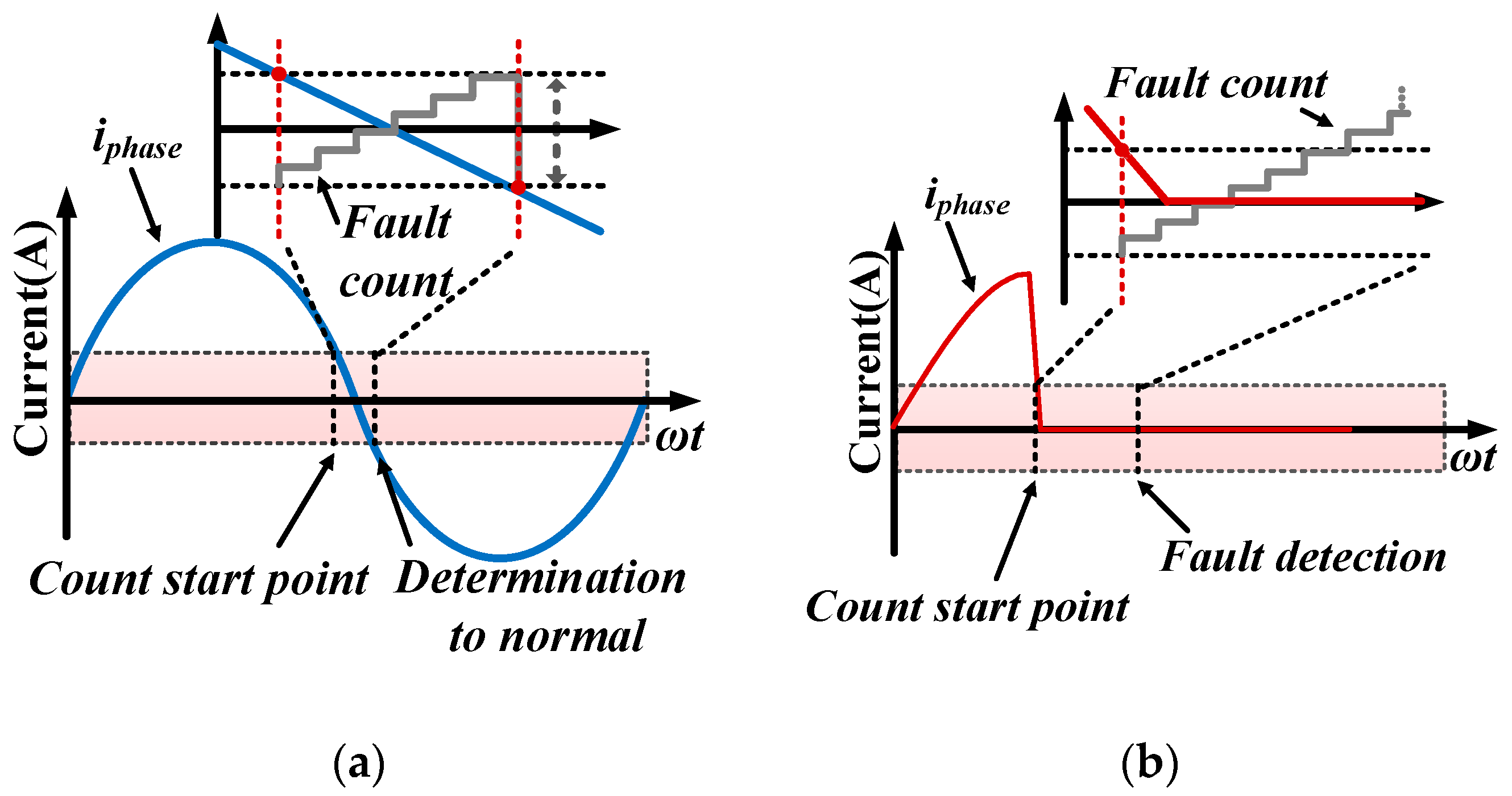
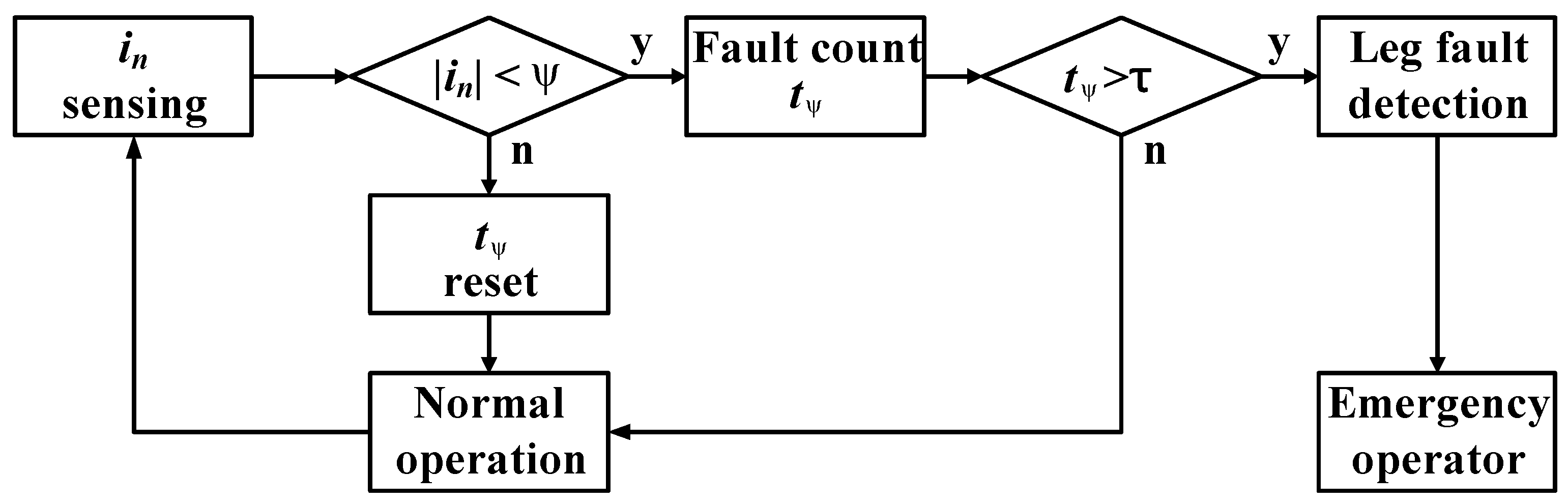
3.2. Proposed Switch Open Fault Diagnosis Algorithm

The threshold point should be derived from theoretically derivable parameters of the AC–DC converter, and the parameters should be calculable without load variation. The current ripple, which is usually measured with the fundamental phase current for current control, is a suitable parameter for calculating the threshold point in grid-tied converters, because the current ripple does not change according to the variation of the phase current. The current ripple is only designed to satisfy 5% of the total harmonic distortion standard using the designed filter and considering the relationship between the modulation index (ma) and the damping ratio of the filter. Figure 5 presents the simulation waveform of the current ripple with respect to load variation in the grid-tied system. As shown in Figure 5, the current ripple is constant regardless of the phase current magnitude. Therefore, the threshold point can be calculated using the current ripple for switch fault diagnosis.
To determine the threshold point using the current ripple, the magnitude of the current ripple and the time the current remains nearly zero should be defined depending on whether this occurs before or after the switch fault. Figure 6a,b present a phase current considering the ripple on the AC–DC converter before and after the switch fault condition, respectively. In Figure 6, the switch fault is detected by ψ, which represents the magnitude of the current ripple, and τ, which represents the time during which the current was near zero. To calculate τ, the instantaneous phase current value that contains the maximum current ripple should be determined as (2). For considering the maximum current ripple, the harmonic current from switching is approximated using the filter damping ratio ζ in (2). It is difficult to obtain τ directly using (2); therefore, the maximum current ripple +ia and the minimum current ripple −ia are derived by approximating (2), as shown in (3) and (4), respectively. Finally, τ is calculated by the time difference when +ia and −ia are equal to zero, as shown in (5).
i a ( t ) = i a . max * sin ( 2 π f r t ) + ζ i a . max * sin ( 2 π f s w t )
+ i a ( t ) = i a * sin ( 2 π f r t ) + ζ i a . max *
i a ( t ) = i a * sin ( 2 π f r t ) ζ i a . max *
τ = sin 1 ( ζ i a . max * i a * ) π f r
In order to use them for switch fault detection, the parameters ψ and τ need to be theoretically defined. ψ can be defined by considering the maximum current ripple as 5% to satisfy the THD standard. If the general expression of the phase current is zero, ψ can be calculated as 0.05 times the maximum phase current calculated using (2). τ can be calculated continuously by using the time difference of ±ia reaching zero, as shown (5). In the case of a switch normal condition, the time that the phase current remains in the ψ region is shorter than that under an abnormal switch condition. When the switch fails, the time that the phase current remains in the ψ region exceeds τ, which represents the value when the switch fault is detected.
A flow chart explaining the proposed algorithm considering the above-mentioned operation principle is presented in Figure 7. In this flow chart, the fault counter is operated when each phase current is measured within ψ. If the counted time from counting the fault counter, which represents tψ, exceeds the τ, the faulty leg corresponding to the fault condition can be detected. The fault counter is reset when the phase current is no longer in the ψ region and before it reaches the τ region. In the counter reset case, the AC–DC converter is determined to be operating under normal conditions.
Using the proposed algorithm, the simulation is conducted as shown in Figure 8. In the simulation results, the switch fault can be detected by the proposed fault diagnosis algorithm using the variable threshold point in the full load condition. In particular, the fast fault diagnosis can be performed by the decreasing τ according to increasing the loads compared between Figure 9a,b.

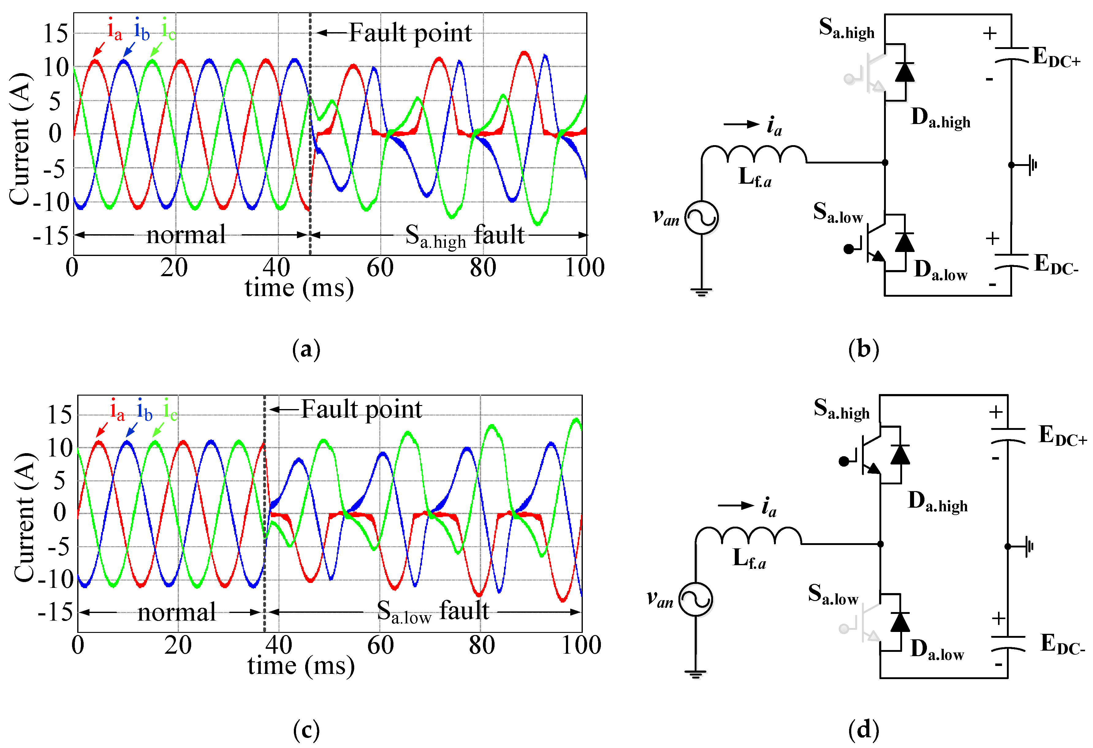
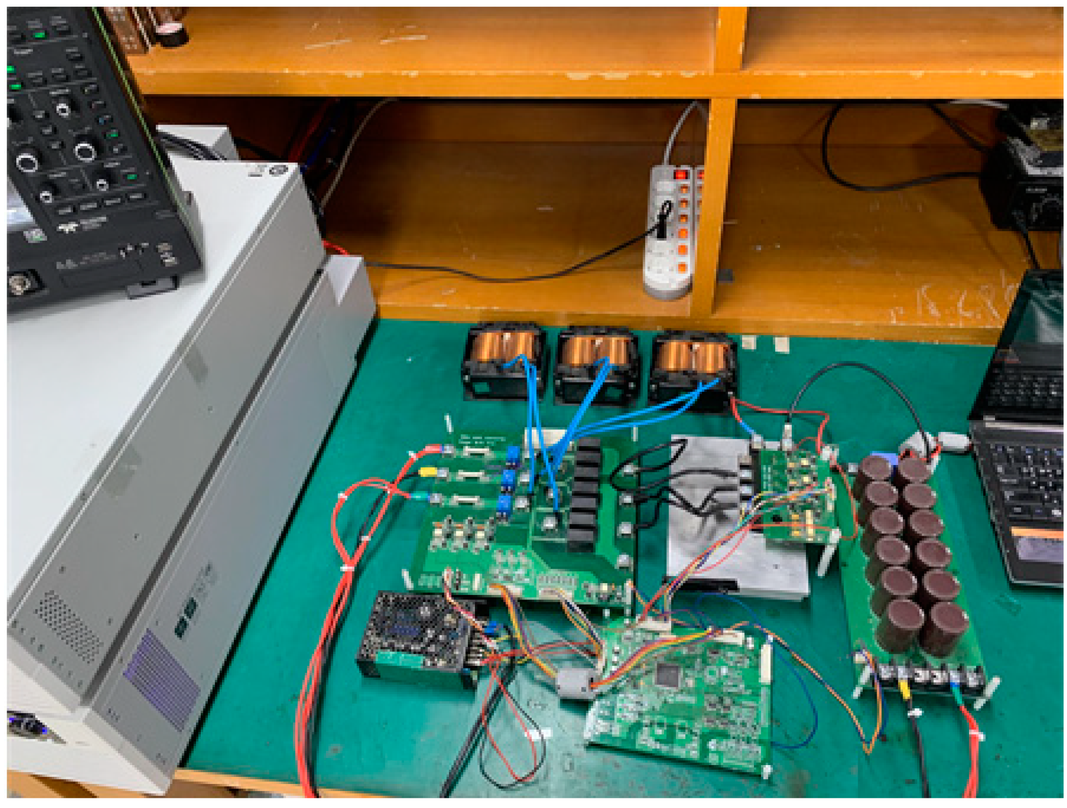
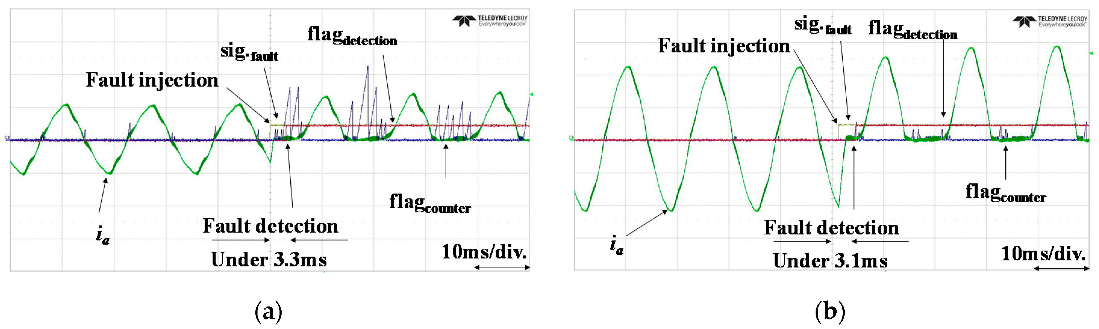
4. Experimental Results

To verify the performance of the proposed diagnosis algorithm, experiments are conducted on a 3-kW prototype test bed, as shown in Figure 10. The parameters listed in Table 1 are used to design the converter and conduct the experiments. The switching frequency is selected to consider the frequency specifications and the losses of the applied IGBT. The filter inductor and the filter capacitor are designed for satisfying the THD standard. The DC link capacitor is constructed for demonstrating the DC grid. In order to exclude the influence of time delay on the fault signal injection and the fault diagnosis, the interruption time of the microcontroller is determined to be 100 µs. A module-type power semiconductor with three legs is used, as shown in Figure 10. To improve the objectivity of the experiment, the switch fault is demonstrated during the converter operation.
Figure 11 shows the waveforms obtained using the fault diagnosis algorithm according to the injected fault signals, which operate to stop the switch. Figure 11a,b show the proposed fault diagnosis waveform with a light load condition and a full load condition, respectively. The fault signal flag indicates the time of the fault situation. The fault detection flag means the time of the fault detection, which is obtained by the proposed algorithm. Before the fault occurs, the value of the fault counter is maintained under the threshold value. After the switch fault occurs, the fault counter exceeds the threshold value, and the switch fault is detected, as seen by the increase in the fault detection flag. The switch fault is detected within 4 ms, as shown in Figure 11a,b. Thus, using the proposed algorithm, switch fault diagnosis can be achieved within 4 ms.

5. Conclusions

In order to achieve fast switch fault diagnosis to improve the system resilience of AC–DC converters on a grid-tied system, a switch fault diagnosis algorithm using instantaneous phase current is proposed. To this end, the characteristics of the phase current are analyzed to calculate the threshold point that represents the value for a switch fault or no-fault. Using the proposed threshold calculation method, the time to fault diagnosis is effectively improved without the magnitude of the phase current. From these results, the proposed algorithm can achieve the fast switch fault diagnosis and can satisfy the recommended standard of UPS without any extra hardware. The proposed fault diagnosis algorithm is verified with simulations and experimental results. A 3-kW experimental test-bed is constructed to implement the actual switch fault condition.

Author Contributions

Conceptualization, G.W.K. and D.J.; Methodology, G.W.K. and D.J.; Software, G.W.K.; Validation, G.W.K. and D.J.; Formal Analysis, G.W.K.; Investigation, G.W.K.; Resources, B.K.L.; Data Curation, G.W.K.; Writing—Original Draft Preparation, G.W.K. and B.K.L.; Writing—Review & Editing, G.W.K. and B.K.L.; Visualization, G.W.K.; Supervision, B.K.L.; Project Administration, B.K.L.; Funding Acquisition, B.K.L.

Funding

This work was supported by the Technology Innovation Program (No. 20001101, Hybrid DCDC converter and integrated system for railway vehicle battery pack) funded by the Ministry of Trade, Industry & Energy (MOTIE, Korea).

Conflicts of Interest

The authors declare no conflict of interest.

References

  1. Li, X.; Guo, L.; Li, Y.; Guo, Z.; Hong, C.; Zhang, Y.; Wang, C. A Unified Control for the DC-AC Interlinking Converters in Hybrid AC/DC Microgrids. IEEE Trans. Smart Grid 2018, 9, 6540–6553. [Google Scholar] [CrossRef]
  2. Choi, U.M.; Blaabjerg, F.; Lee, K.B. Study and Handling Methods of Power IGBT Module Failures in Power Electronic Converter Systems. IEEE Trans. Power Electron. 2015, 30, 2517–2533. [Google Scholar] [CrossRef]
  3. Brunson, C.; Empringham, L.; Lillo, L.D.; Wheeler, P.; Clare, J. Open-Circuit Fault Detection and Diagnosis in Matrix Converters. IEEE Trans. Power Electron. 2015, 30, 2840–2847. [Google Scholar] [CrossRef]
  4. Martínez, S.; Castro, M.; Antoranz, R.; Aldana, F. Off-Line Uninterruptible Power Supply with Zero Transfer Time Using Integrated Magnetics. IEEE Trans. Ind. Electron. 1989, 36, 441–445. [Google Scholar] [CrossRef]
  5. Sölter, D.I.W. An international UPS classification by IEC 62040-3. In Proceedings of the 24th Annual International Telecommunications Energy Conference, Montreal, QC, Canada, 29 September–3 October 2002; pp. 541–545. [Google Scholar]
  6. Shahbazi, M.; Poure, P.; Saadate, S.; Zolghadri, M.R. FPGA-Based Reconfigurable Control for Fault-Tolerant Back-to-Back Converter without Redundancy. IEEE Trans. Ind. Electron. 2013, 60, 3360–3371. [Google Scholar] [CrossRef]
  7. Lamb, J.; Mirafzal, B. Open-Circuit IGBT Fault Detection and Location Isolation for Cascaded Multilevel Converters. IEEE Trans. Ind. Electron. 2017, 64, 4846–4856. [Google Scholar] [CrossRef]
  8. Karimi, S.; Gaillard, A.; Poure, P.; Saadate, S. FPGA-Based Real-Time Power Converter Failure Diagnosis for Wind Energy Conversion Systems. IEEE Trans. Ind. Electron. 2008, 55, 4299–4308. [Google Scholar] [CrossRef]
  9. Zhang, H.; Sun, C.; Li, Z.; Liu, J.; Cao, H.; Zhang, X. Voltage Vector Error Fault Diagnosis for Open-Circuit Faults of Three-Phase Four-Wire Active Power Filters. IEEE Trans. Power Electron. 2017, 32, 2215–2226. [Google Scholar] [CrossRef]
  10. Dan, H.; Peng, T.; Su, M.; Deng, H.; Zhu, Q.; Zhao, Z.; Wheeler, P. Error-Voltage-Based Open-Switch Fault Diagnosis Strategy for Matrix Converters with Model Predictive Control Method. IEEE Trans. Ind. Appl. 2017, 53, 4603–4612. [Google Scholar] [CrossRef]
  11. Mendes, A.M.S.; Cardoso, A.J.M. Voltage source inverter fault diagnosis in variable speed AC drives, by the average current Park’s vector approach. In Proceedings of the IEEE International Electric Machines and Drives Conference, IEMDC’99, Seattle, WA, USA, 9–12 May 1999; pp. 704–706. [Google Scholar]
  12. Ribeiro, R.L.A.; Jacobina, C.B.; Silva, E.R.C.; Lima, A.M.N. Fault Detection of Open-Switch Damage in Voltage-Fed PWM Motor Drive Systems. IEEE Trans. Power Electron. 2003, 18, 587–593. [Google Scholar] [CrossRef]
  13. Duan, P.; Xie, K.; Rong, X. Open-Switch Fault Diagnosis and System Reconfiguration of Doubly fed Wind Power Converter Used in a Microgrid. IEEE Trans. Power Electron. 2011, 26, 816–821. [Google Scholar] [CrossRef]
  14. Choi, U.M.; Jeong, H.G.; Lee, K.B.; Blaabjerg, F. Method for Detecting an Open-Switch Fault in a Grid-Connected NPC Inverter System. IEEE Trans. Power Electron. 2012, 27, 2726–2739. [Google Scholar] [CrossRef]
  15. Khomfoi, S.; Eae-Kok, W.; Ngamoroo, I. An Open Circuit Fault Diagnostic Technique in IGBTs for AC to DC Converters Applied in Microgrid Applications. J. Power Electron. 2011, 11, 801–810. [Google Scholar] [CrossRef]
  16. Lu, B.; Sharma, S.K. A Literature Review of IGBT Fault Diagnostic and Protection Methods for Power Inverters. IEEE Trans. Ind. Appl. 2009, 45, 1770–1777. [Google Scholar]
  17. Peuget, R.; Courtine, S.; Rognon, J.P. Fault detection and isolation on a PWM inverter by knowledge-based model. IEEE Trans. Ind. Appl. 1998, 34, 1318–1326. [Google Scholar] [CrossRef]
  18. Lee, J.S.; Lee, K.B.; Blaabjerg, F. Open-Switch Fault Detection Method of a Back-to-Back Converter Using NPC Topology for Wind Turbine Systems. IEEE Trans. Ind. Appl. 2015, 51, 325–335. [Google Scholar] [CrossRef]
  19. Choi, U.M.; Lee, K.B.; Blaabjerg, F. Diagnosis and Tolerant Strategy of an Open-Switch Fault for T-Type Three-Level Inverter Systems. IEEE Trans. Ind. Appl. 2014, 50, 495–508. [Google Scholar] [CrossRef]
  20. Rothenhagen, K.; Fuchs, F.W. Performance of Diagnosis Methods for IGBT Open Circuit Faults in Voltage Source Active Rectifiers. In Proceedings of the IEEE 35th Annual Power Electronics Specialist Conference, Aachen, Germany, 20–25 June 2004; pp. 4348–4354. [Google Scholar]
  21. Lee, J.S.; Choi, U.M.; Lee, K.B. Comparison of Tolerance Controls for Open-Switch Fault in a Grid-Connected T-Type Rectifier. IEEE Trans. Power Electron. 2015, 30, 5810–5820. [Google Scholar] [CrossRef]
  22. Choi, U.M.; Lee, J.S.; Lee, K.B. New Modulation Strategy to Balance the Neutral-Point Voltage for Three-Level Neutral-Clamped Inverter Systems. IEEE Trans. Energy Convers. 2014, 29, 91–100. [Google Scholar] [CrossRef]
  23. Choi, U.M.; Lee, J.S.; Blaabjerg, F.; Lee, K.B. Open-Circuit Fault Diagnosis and Fault-Tolerant Control for a Grid-Connected NPC Inverter. IEEE Trans. Power Electron. 2016, 31, 7234–7247. [Google Scholar] [CrossRef]
  24. Zhang, W.; Xu, D.; Enjeti, P.N.; Li, H.; Hawke, J.T.; Krishnamoorthy, H.S. Survey on Fault-Tolerant Techniques for Power Electronic Converters. IEEE Trans. Power Electron. 2014, 29, 6319–6331. [Google Scholar] [CrossRef]
  25. Rashid, G.; Ali, M.H. Transient Stability Enhancement of Doubly Fed Induction Machine-Based Wind Generator by Bridge-Type Fault Current Limiter. IEEE Trans. Energy Convers. 2015, 30, 939–947. [Google Scholar] [CrossRef]
  26. Kong, X.; Zhang, Z.; Yin, X.; Wen, M. Study of Fault Current Characteristics of the DFIG Considering Dynamic Response of the RSC. IEEE Trans. Energy Convers. 2014, 29, 278–287. [Google Scholar]
Figure 1. Alternating current (AC)–direct current (DC) converter for considering switch fault in the hybrid grid system.
Energies 12 01979 g001
Figure 2. Current characteristic and equivalent circuit in the switch fault condition: (a) phase A high-side switch fault simulation waveform; (b) equivalent circuit of phase A high-side switch fault; (c) phase A low-side switch fault simulation waveform; (d) equivalent circuit of phase A low-side switch fault.
Energies 12 01979 g002
Figure 3. Principle of previous switch fault diagnosis algorithm: (a) switch normal condition; (b) switch fault condition.
Energies 12 01979 g003
Figure 4. Problem of inaccurate threshold point: (a) problem of high threshold point; (b) problem of low threshold point.
Energies 12 01979 g004
Figure 5. Phase current waveform in a grid-tied AC–DC converter: (a) phase current in the light load condition; (b) phase current in the full load condition; (c) fundamental current waveform in the light load condition; (d) fundamental current waveform in the full load condition; (e) ripple current waveform in the light load condition; (f) ripple current waveform in the full load condition.
Energies 12 01979 g005aEnergies 12 01979 g005b
Figure 6. Principle of proposed switch fault diagnosis algorithm with threshold point calculation: (a) τ of switch normal condition; (b) τ of switch fault condition.
Energies 12 01979 g006
Figure 7. Flow chart of the proposed fault diagnosis algorithm.
Energies 12 01979 g007
Figure 8. Simulation waveform of the proposed algorithm: (a) Fault diagnosis operation in the light load condition; (b) Fault diagnosis operation in the full load condition.
Energies 12 01979 g008
Figure 9. Variation of τ according to the load condition: (a) small τ in full load condition; (b) large τ in light load condition.
Energies 12 01979 g009
Figure 10. 3-kW experimental test-bed for fault diagnosis of AC–DC converter.
Energies 12 01979 g010
Figure 11. Experimental waveform of switch fault diagnosis: (a) switch fault diagnosis with proposed algorithm at 1300 W; (b) switch fault diagnosis with proposed algorithm at 3000 W. Time: 10 ms/div., phase current (ia): 5A/div., fault signal flag (sig.fault): 1V/div., fault detection flag (flagdetection): 1V/div., fault counter flag (flagcounter): 1Vdiv.
Energies 12 01979 g011
Table 1. Parameters of 3-kW AC–DC converter system.
ParameterValue[Unit]ParameterValue [Unit]
Input voltage, Vin220[Vrms]Filter inductance, Lf3.2 [mH]
Output voltage, Vout380[Vdc]Filter capacitance, Cf4 [uF]
Grid frequency, fgrid60[Hz]DC link capacitor, Cdclink 2 [mF]
Power rate, Prated3[kW]Threshold time, τ0.3–1 * margin-
Switching frequency, fsw15[kHz]Magnitude of current ripple, ψ1.1 [A]

