Article

A Research on Cascaded H-Bridge Module Level Photovoltaic Inverter Based on a Switching Modulation Strategy

1
School of Electrical Engineering and Automation, Hefei University of Technology, Hefei 230009, China
2
Sungrow Power Supply Co., Ltd., Hefei 230088, China
*
Author to whom correspondence should be addressed.
Energies 2019, 12(10), 1851; https://doi.org/10.3390/en12101851
Submission received: 28 April 2019 / Revised: 7 May 2019 / Accepted: 13 May 2019 / Published: 15 May 2019

Abstract

:
The stable operating region of a photovoltaic (PV) cascaded H-bridge (CHB) grid-tied module level inverter is extended by adopting the hybrid modulation strategy. However, the traditional single hybrid modulation method is unable to regulate the DC-side voltage of each module precisely, which may aggravate the fluctuation of modules’ DC-side voltages or even cause the deviation of modules’ DC-side voltages under some fault conditions and, thus, degrade the energy harvesting of PV panels. To tackle this problem, a switching modulation strategy for PV CHB inverter is proposed in this paper. When the CHB inverter is operating in normal mode, the hybrid modulation strategy containing the zero state is adopted to suppress DC-side voltage fluctuation, thereby, improving the output power of PV modules. When the CHB inverter is operating in fault mode owing to failing solar panels, the hybrid modulation strategy without the zero state is utilized to make the DC-side voltages reach the references and, thus, maintain a higher energy yield under fault conditions. Experimental results achieved by a laboratory prototype of a single-phase eleven-level CHB inverter demonstrate both the feasibility and effectiveness of the proposed method.

1. Introduction

With the increasing demand for conversion efficiency during recent years, multilevel converter topologies have become more and more applied to the grid-connected PV generation system [1,2,3,4]. Among all kinds of multilevel inverters, the cascaded H-bridge (CHB) has many advantages, such as modularization, simplicity, and high reliability, which makes it become the most attractive topology [5,6,7,8,9]. In addition, the CHB topology makes it possible to, respectively, regulate each DC-side voltage and, thus, realizing the maximum power point tracking (MPPT) of each PV module. Therefore, the CHB inverter is considered to be one of the most suitable candidates for next generation PV inverters [10,11].
The energy loss caused by non-uniform solar radiation, degradation of PV modules and different types of partial shading is greatly decreased by module level MPPT. However, due to the unequal temperature and irradiance of PV modules, the output power of H-bridge unit varies greatly in the case of severe mismatching. This may lead to over-modulation of H-bridge units with high output power, thus, resulting in system instability and injection current distortion [12].
For the sake of expanding the stable operation range of the CHB inverter, some methods have been proposed. The power balance control strategy based on active component modification of duty cycles, and its effective power balance area are proposed in [13,14,15]. Although the system can operate stably by utilizing this method under slight mismatch conditions, there are still instability problems under severe mismatch conditions. In [16,17], a control strategy of reactive power compensation is proposed, which utilizes the power factor as the degree of freedom to stabilize the operation of the system. However, an increase in reactive power injection will lead to a decrease of the system power factor, which may be undesirable from the perspective of electric dispatchers. A new, improved MPPT method is presented in [18], which changes the working point of the over-modulated H-bridge unit to ensure that all H-bridge units work in the stable operation region to improve the stability margins of the system. However, this will result in lower output power and make the system less-efficient. This is contrary to the original intention that all PV modules operate at a maximum power point to realize higher efficiency in energy harvesting.
Hopefully, In [19,20,21], the hybrid modulation strategy (HMS) is proposed, which utilizes a mixture of low-frequency PWM and high-frequency PWM methods to regulate the DC-side voltage and control the AC current separately. The HMS has been proved to maintain the stabilization of power rectifiers effectively even under critical operating conditions, because it provides higher DC-side utilization (the maximum modulation index of square wave can reach 4/π) compared with conventional sinusoidal pulse width modulation (SPWM). In [22,23], a control method of a grid-connected PV CHB inverter is proposed, which is based on the hybrid modulation strategy containing the zero state (HMSCZS). With HMSCZS, the system can operate stably under heavy mismatching conditions. Once the CHB inverter is operating in the fault mode, owing to failing solar panels, the HMSCZS fails to regulate the DC-side voltages to the references and may lead to low output power of the inverter. In [24], the hybrid modulation strategy without the zero state (HMSWZS) is proposed to maximize the range of stable operation of system. However, the HMSWZS cannot control the DC-side voltage of each module accurately. This may aggravate the fluctuation of modules’ DC-side voltages, thus resulting in the decrease of the generated energy of PV modules.
Therefore, a switching hybrid modulation strategy (SHMS) is proposed in this paper. The HMSCZS is selected to suppress DC-side voltages fluctuation when the CHB inverter is operating in normal mode. Once the CHB inverter is operating in fault mode, owing to failing solar panels, the HMSWZS is utilized to control the DC-side voltages to track the references, thus maintaining a higher energy yield under fault condition. With this method, the average output power of the PV modules will be improved both in the normal and fault modes.
The paper is arranged as follows: In Section 2, the system configuration and control method are introduced. In Section 3, the existing problem of the HMSCZS and the HMSWZS is shown. In Section 4, the switching hybrid modulation strategy is put forward. In Section 5 and Section 6, the performance of the proposed strategy is verified by simulation and experimental results. Finally, in Section 7, a conclusion is drawn to summarize the paper.

2. System Configuration

The structure of the single-phase PV CHB module level grid-tied inverter is shown in Figure 1. The CHB module level inverter consists of m H-bridge units. Each H-bridge unit is connected to a PV module. VPVi and IPVi (I = 1, 2, …, m) stand for the output voltage and current of PV module of ith H-bridge. ICi represents the current flowing through the capacitor on the DC-side of ith H-bridge. VG stands for grid voltage. IS stands for grid current. VHi (I = 1, 2, …, m) is the ith H-bridge output voltage and VHT is the total output voltage of H-bridges. Figure 2 shows the configuration of the control diagram of CHB module level inverter. The voltage and current double closed-loop control are utilized to obtain the goal of the controlling. In order to decrease third harmonic component in the grid current, a digital 100 Hz notch filter is utilized to eliminate the second order harmonic in the total DC-side voltage VPV1 + VPV2••• + VPVm. The external voltage loop is in charge of controlling the filtered total DC-side voltages to the sum of the references VPV1* + VPV2*••• + VPVm* by a conventional PI controller. The internal current loop is responsible for controlling the grid current to a sinusoidal shape in phase with the grid voltage. In the paper, a direct-quadrature rotating frame control method for the single-phase inverter is used to achieve this goal because it can achieve zero steady-state error by utilizing a traditional PI regulator [25]. The output of the current loop regulator, Vr, serves as the modulation wave. In order to compensate for the harmonic component of the CHB inverter caused by the distorted grid voltage, the third, fifth, and seventh harmonic compensation algorithm is utilized [26,27].
The balancing algorithm allocates suitable switching modes to each unit during every switching period based on the instantaneous value of modulation wave. For HMSCZS, only one unit operates in PWM state, the K − 1(K = 1, 2, …, m) units operate in the “+1” or “−1” state and other units work in the “0” state. However, for HMSWZS, only one unit operates in the PWM state, while the other units work in the “+1” or “−1” mode. Probable switching states of the ith unit, Si, and their corresponding output voltages are given in Table 1.

3. Review of The Existing Hybrid Modulation Strategy

3.1. The Hybrid Modulation Strategy Containing the Zero State (HMSCZS)

The HMSCZS proposed in [19,23] maximizes the steady operation range of the system, because it provides higher DC-side utilization by adopting a square wave modulation. The major procedures of HMSCZS can be summarized as follows:
(1)
Calculating the voltage error ∆VPVi (I = 1, 2, …, m) at the DC-side of each H-bridge unit:
Δ V PV i = V PV i V PV i *
(2)
Sorting the voltage errors in ascending order ([∆VPV1, ∆VPV2, …, ∆VPVm]) at a fixed frequency, fsort.
(3)
Mapping for the filtered DC-side voltages derived from the sorted vector of voltage errors ([V1, V2, …, Vm]).
(4)
Identifying the voltage area l of Vr based on Equation (2):
i = 1 l - 1 V i < | V r | < i = 1 l V i
(5)
Updating the H-bridge units’ operating state. The l − 1 (l = 1, 2, …, m) units with the higher DC-side voltage are selected to be discharged in state “+1” or “−1” (according to the direction of grid-connected current), the lth unit works in the PWM state, and the rest operate in state “0”.
As shown in Figure 3, the switching modes for an eleven-level CHB inverter with the HMSCZS method is presented. For instance, when i = 1 3 V i < V r < i = 1 4 V i and I S > 0 , the switching modes of the five H-bridge modules are, respectively, “0”, “+PWM”, “+1”, “+1”, and “+1”. According to the rules of HMSCZS, the switching mode of each H-bridge unit can only be “+1”, “0”, or “+PWM” when Vr is positive. Similarly, it can only be “−1”, “0”, or “−PWM” when Vr is negative. As shown in Figure 4, once the CHB inverter is operating in fault mode owing to failing PV modules, the fault H-bridge unit is always in the discharge state, whether the switching mode is “+1”, “+PWM”, “−1” or “−PWM”. The result is that the DC-side voltages of all H-bridge units diverge from the reference value and the generation of CHB inverter is low.

3.2. The Hybrid Modulation Strategy without the Zero State (HMSWZS)

To overcome the shortcoming of the HMSCZS, the HMSWZS is presented in [21,24]. Different from the HMSCZS, in the HMSWZS the units with the lower voltage errors are selected to be charged in state “+1” or “−1” (according to the direction of grid-connected current) and no unit operates in the “0” mode. Figure 5 shows the switching modes for an eleven-level CHB inverter with the HMSWZS method. As depicted in the Figure 5, when i = 1 1 V i < V r < i = 1 2 V i and I S > 0 , the switching modes of the five H-bridge modules are, respectively, “−1”, “−PWM”, “+1”, “+1”, and “+1”. According to the rules of HMSWZS, as shown in Figure 6, the switching mode of the fault H-bridge unit can be “+1”, “+PWM”, “−1”, or “−PWM” regardless of the polarity of Vr. Therefore, compared with the HMSCZS, the HMSWZS is able to maintain the DC-side voltages balance and a higher energy yield under fault condition.
However, as is illustrated in [23], the HMSWZS may aggravate the DC-side voltages fluctuation of H-bridge units and, thus, lead to losses in energy harvesting of PV modules. As shown in Equation (3), ∆Uci (i = 1, 2, …, m), the fluctuation of the DC-side voltage of the ith H-bridge unit during a sorting cycle is composed of two parts: ∆Uci1 and ∆Uci2. Based on the superposition theorem of linear circuits, the fluctuation of the DC-side voltage could be regarded as the sum of fluctuations produced by two separate parts:
Δ U c i = 1 C i 0 1 f s o r t ( I PV i S i I s ) d t = I PV i C i f s o r t 1 C i 0 1 f s o r t S i I s d t = Δ U c i 1 + Δ U c i 2
where:
Δ U c i 1 = I PV i C i f s o r t
Δ U c i 2 = 1 C i 0 1 f s o r t S i I s d t
If the HMSWZS is utilized, ∆Uci has two possible values: ∆U1min and ∆U1max (if the polarity of Si and Is is the same, ∆Uci = ∆U1min, otherwise, ∆Uci = ∆U1max), where:
Δ U 1 min = Δ U c i 1 | Δ U c i 2 | Δ U 1 max = Δ U c i 1 + | Δ U c i 2 |
If the HMSCZS is employed, ∆Uci also has two possible values: ∆U2min and ∆U2max (if the value of Si is not equal to zero, ∆Uci = ∆U2min, otherwise, ∆Uci = ∆U2max), where:
Δ U 2 min = Δ U c i 1 | Δ U c i 2 | Δ U 2 max = Δ U c i 1
It is obvious that ∆U1min is equal to ∆U2min and ∆U1max is greater than ∆U2max. Compared with the HMSCZS, the HMSWZS may lead to larger fluctuation of DC-side voltages of H-bridge units and thus more energy will be lost.

4. The Switching Hybrid Modulation Strategy

A switching hybrid modulation strategy (SHMS) based on the HMSCZS and HMSWZS is proposed to maximize the output power of PV panels. When the CHB inverter is operating in the normal mode, the HMSCZS is adopted to suppress DC-side voltages fluctuation and, thus, realizing higher efficiency in energy harvesting. When the CHB inverter is operating in the fault mode owing to failing solar panels, the HMSWZS is utilized to control the DC-side voltages to reach the references, thus, maintaining a higher energy yield under the fault condition. Figure 7 shows the major procedures of the SHMS, which are basically the same as HMSCZS.
In consideration of the direction of IS and Vr, and assuming that the modulation wave Vr is in area l, the SHMS method allocates suitable switching modes to each H-bridge unit based on the following rules:

4.1. Normal Mode

(1)
When (Vr > 0 and IS > 0), (l − 1) units with higher voltage errors are discharging in the “+1” state, (ml) units with lower voltage errors operate in the “0” state, and the lth unit works in PWM state.
(2)
When (Vr > 0 and IS ≤ 0), (l − 1) units with lower voltage errors are charging in the “+1” state, (ml) units with higher voltage errors operate in the “0” state, and the lth unit works in the PWM state.
(3)
When (Vr ≤ 0 and IS > 0), (l − 1) units with lower voltage errors are charging in the “−1” state, (ml) units with higher voltage errors operate in the “0” state, and the lth unit works in the PWM state.
(4)
When (Vr ≤ 0 and IS ≤ 0), (l − 1) units with higher voltage errors are discharging in the “−1” state, (ml) units with lower voltage errors operate in the “0” state, and the lth unit works in the PWM state.

4.2. Fault Mode

(1)
When (Vr > 0 and IS > 0), and the value of (ml) is even, (ml)/2 units with lower voltage errors are charging in the “−1” state, the ((ml + 2)/2)th unit works in the PWM state, and the remaining units operate in the “+1” state.
(2)
When (Vr > 0 and IS > 0), and the value of (ml) is uneven, (ml − 1)/2 units with lower voltage errors are charging in the “−1” state, the ((ml + 1)/2)th unit works in the PWM state, and the remaining units operate in the “+1” state.
(3)
When (Vr > 0 and IS ≤ 0), and the value of (ml) is even, (m + l − 2)/2 units with lower voltage errors are charging in the “+1” state, the ((m + l)/2)th unit works in the PWM state, and the remaining units operate in the “−1” state.
(4)
When (Vr > 0 and IS ≤ 0), and the value of (ml) is uneven, (m + l − 1)/2 units with lower voltage errors are charging in the “+1” state, the ((m + l + 1)/2)th unit works in the PWM state, and the remaining units operate in the “−1” state.
(5)
When (Vr ≤ 0 and IS > 0), and the value of (ml) is even, (m + l − 2)/2 units with lower voltage errors are charging in the “−1” state, the ((m + l)/2)th unit works in the PWM state, and the remaining units operate in the “+1” state.
(6)
When (Vr ≤ 0 and IS > 0), and the value of (ml) is uneven, (m + l − 1)/2 units with lower voltage errors are charging in the “−1” state, the ((m + l + 1)/2)th unit works in the PWM state, and the remaining units operate in the “+1” state.
(7)
When (Vr ≤ 0 and IS ≤ 0), and the value of (ml) is even, (ml)/2 units with lower voltage errors are charging in the “+1” state, the ((ml + 2)/2)th unit works in the PWM state, and the remaining units operate in the the “−1” state.
(8)
When (Vr ≤ 0 and IS ≤ 0), and the value of (ml) is uneven, (ml − 1)/2 units with lower voltage errors are charging in the “+1” state, the ((ml + 1)/2)th unit works in the PWM state, and the remaining units operate in the “−1” state.

5. Simulation Verification
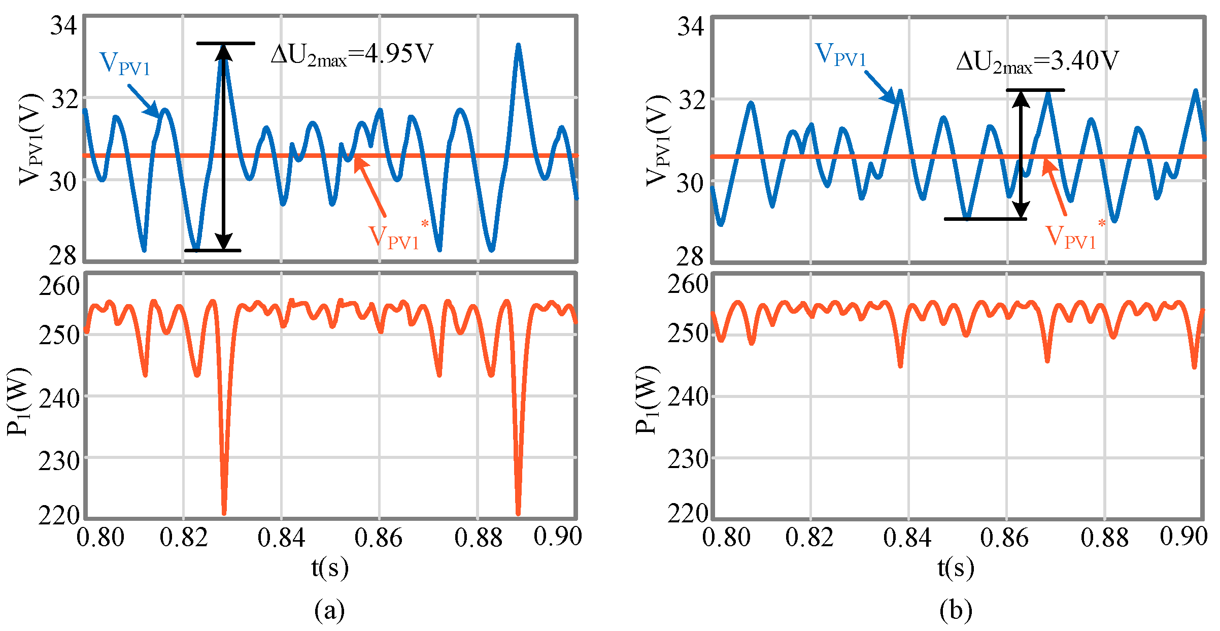
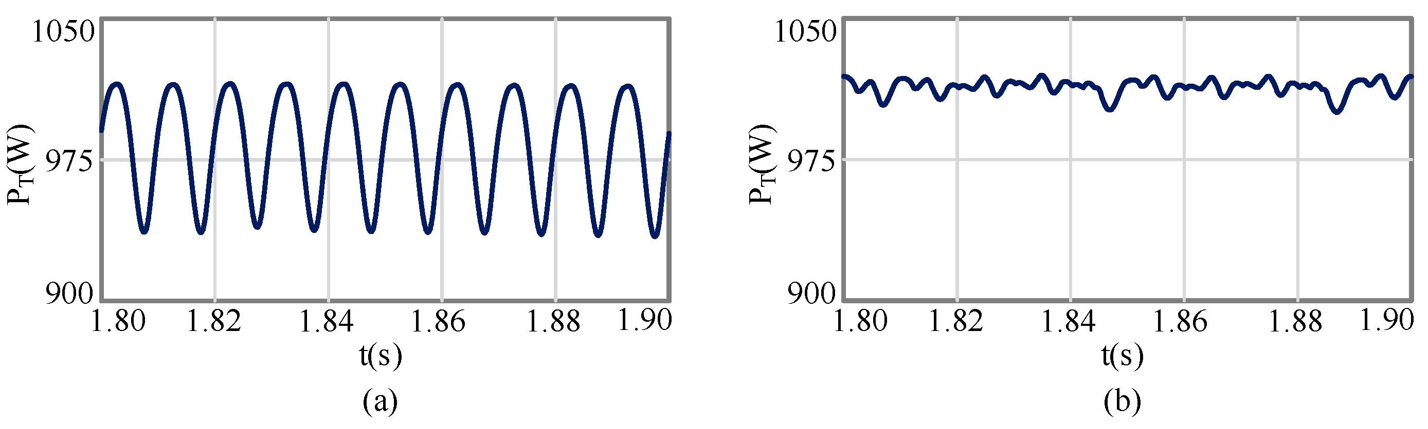
To verify the performance of the proposed method, an CHB inverter which consists of five modules is simulated in MATLAB/Simulink. The PV panel is a JAP6-60-255/4BB and the specifications and equivalent circuit parameters are given in Table 2. Table 3 shows the inverter and grid parameters.

5.1. Normal Mode

In order to investigate the performance of both HMSWZS and SHMS in terms of DC-side voltage fluctuation and average output power of the PV module under identical conditions, the DC-side voltage (VPV1) and output power (P1) of the PV module in the first H-bridge are shown in Figure 8. The simulation starts with the operation of the system under symmetrical condition (E = 1000 W/m2 and T = 25 °C). In the simulation, since the focus of this paper is to study the influence of DC-side voltage fluctuation on the energy acquisition of PV module, the reference of the DC-side voltage is set directly at the maximum power point of PV module instead of adopting the MPPT algorithm. As shown in Figure 8, the maximum fluctuation of VPV1 is 4.95 V when HMSWZS is utilized, while that of SHMS is only 3.40 V, which is reduced by up to 31.30%. With the HMSWZS, the output power of the first PV module ranges from 220–255.1 W, and the average is about 251.9 W. Since the SHMS is utilized to reduce the DC-side voltage fluctuation, the output power ranges from 245–255.1 W and the average is about 253.4 W. Figure 9 shows the total output power (PT) of the CHB inverter with both methods. As shown in Figure 9, with HMSWZS, the total output power of the CHB inverter ranges from 1243–1275 W and the average is about 1262 W. When SHMS is utilized, the total output power of the CHB inverter ranges from 1256–1277 W and the average is about 1269.2 W. Compared with the HMSWZS, the efficiency of the CHB inverter can be improved about 0.56% by adopting the SHMS. Therefore, under the normal mode, the SHMS has a superior capacity of suppressing the DC-side voltage fluctuation compared with the HMSWZS, thereby improving the energy collection of the PV module.

5.2. Fault Mode

The following simulation evaluates the performance of HMSCZS and SHMS under the fault mode where the second PV module fails. The simulation starts with the operation of the system under symmetrical condition (E = 1000 W/m2 and T = 25 °C). At t = 1.5 s, the second PV module is removed owing to the fault and, thus, the CHB inverter is operating in the fault condition. Figure 10 depicts the total modulation voltage (Vr) and DC-side capacitor current of the second H-bridge (IC2) with both methods. As shown in Figure 10a IC2 is always negative regardless of the polarity of Vr and, thus, VPV2 gradually diverges from the reference value. As a result, all the DC-side voltages diverge from the references in steady state, which is visible in Figure 11a. For comparison, the SHMS is also subjected to the same test under the identical condition. As presented in Figure 10b, IC2 can be positive and negative whether Vr is positive or negative and, thus, the DC-side capacitor of the second H-bridge could realize the equalization of the charge-discharge. Therefore, the CHB inverter is able to operate properly under fault condition, which is obvious in Figure 11b. Figure 12 shows the output power of the PV module in all H-bridges with both methods. As shown in Figure 12, due to the removal of the second PV module, the output power of the second H-bridge is, therefore, zero. The output power of the PV module in other H-bridges ranges from 243.2–255.1 W by using SHMS and the average is about 253.2 W. However, due to the deviation of the DC-side voltage, the output power of the PV module in other H-bridges ranges from 221.4–255.1 W by utilizing HMSCZS and the average is only about 245.3 W. The total output power (PT) of the CHB inverter with both methods are shown in Figure 13. As could be seen from Figure 13, with HMSCZS, the total output power of the CHB inverter ranges from 935.9–1016 W and the average is about 982.2 W. When SHMS is utilized, the total output power of the CHB inverter ranges from 1000–1020 W and the average is about 1014 W. Compared with the HMSCZS, the efficiency of the CHB inverter can be improved about 3.12% by adopting the SHMS. Therefore, under the fault mode, the SHMS is still able to make the DC-side voltages reach the references, thus maintaining a higher energy yield.

6. Experimental Results
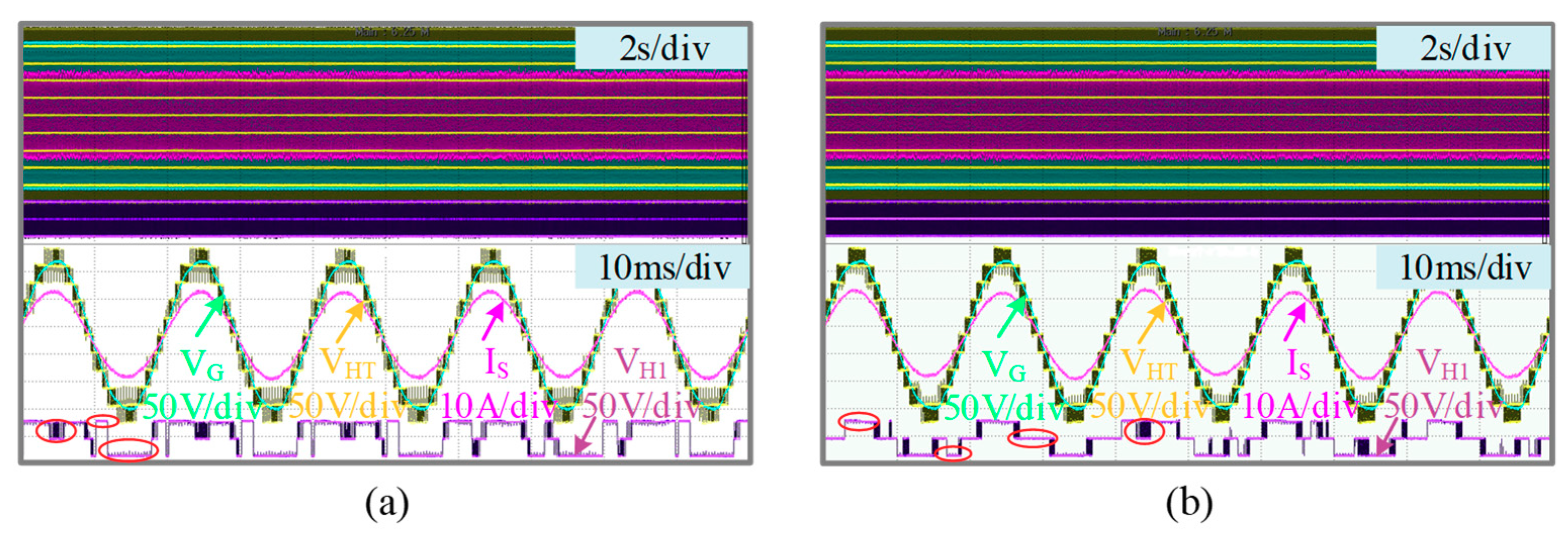
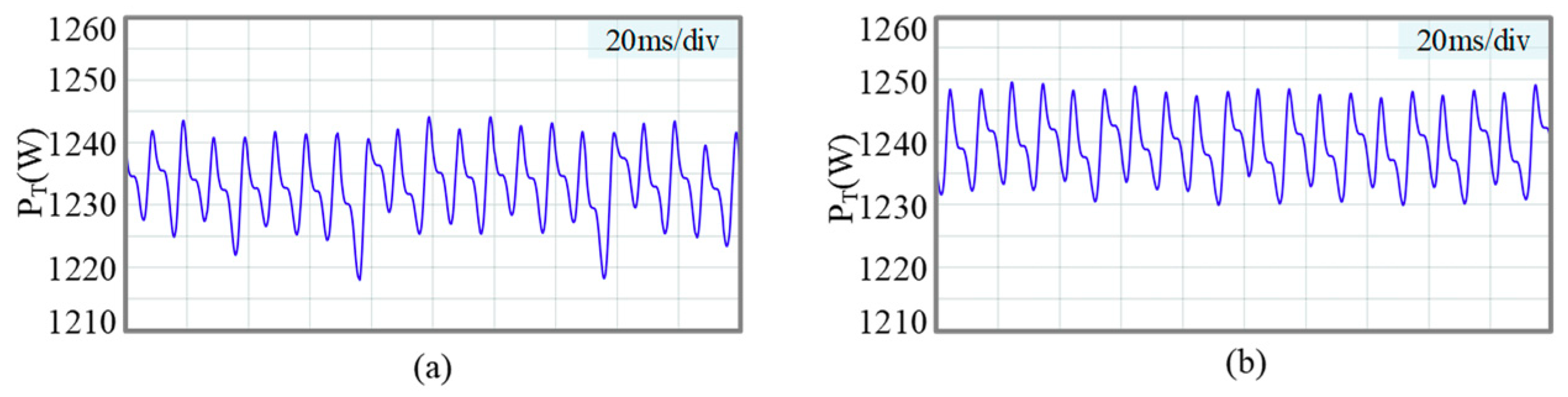
As shown in Figure 14, an experimental prototype with five H-bridge units has been established to validate the effectiveness of the proposed strategy. The prototype includes a central controller and five local controllers. The BECKHOFF industrial PC (CX2040) is utilized as the central controller and TMS320F28335 processors are used as local controllers which communicate with each other through an EtherCAT real-time communication network. The EtherCAT protocol features not only enhance the effective synchronization between master and slave clocks, but also improves the synchronization between the H-bridge units. Since the testing equipment of the university laboratory is limited, only the first H-bridge unit is connected to a Chroma62020H-150S PV simulator, and the DC side of the four other H-bridge units are connected to a 36 V switching power supply through a 0.5 Ω resistance, respectively, to simulate PV modules. Given that there are only five H-bridge units in the experiment, the output of the inverter is connected to the 130 V AC grid regulated by a voltage regulator. The other parameters of the experimental system are the same as the simulation parameters.

6.1. Normal Mode

The first experiment has been carried out under the initial conditions of PV simulator with irradiance of 1000 W/m2 and a temperature of 25 °C. In this case, the input power of the first H-bridge unit is approximately 255 W. The reference of the other four H-bridge units’ DC-side voltages is 32.02 V, and therefore the output power of the other four H-bridges is about 255 W in theory. As depicted in the Figure 15, both SHMS and HMSWZS enable the CHB inverter to operate at unity power factor with good grid current quality. It can also be seen that SHMS contains four output modes: “+1”, “−1”, PWM, and “0” mode, which is never adopted in HMSWZS.
For the sake of evaluating the characteristic of both two modulation methods in terms of DC-side voltage fluctuation and average output power of the PV module, the following experiments have been performed under the same conditions as the first experiment. As shown in Figure 16, the maximum fluctuation of VPV1 by adopting HMSWZS is 5.3 V, but the value is only 4.1V for SHMS, which is reduced by about 22.64%. In order to compare the output power of the two methods under normal mode, the total output power of the CHB inverter is recorded by the upper computer, respectively. As can be seen from Figure 17, with HMSWZS, the total output power of the CHB inverter ranges from 1218–1244.2 W and the average is about 1233.7 W. When SHMS is utilized, the total output power of the CHB inverter ranges from 1230–1249.3 W and the average is about 1239.8 W. Compared with the HMSWZS, the efficiency of the CHB inverter can be improved about 0.48% by adopting the SHMS. Furthermore, the efficiency of the CHB inverter with both methods is presented in Figure 18. As can be seen from Figure 18, the SHMS is capable of improving the efficiency of the CHB inverter compared with the HMSWZS. Therefore, under normal mode, the SHMS is able to effectively suppress the DC-side voltage fluctuation compared with the HMSWZS, thereby improving the energy acquisition of the PV module.

6.2. Fault Mode

The last experiment is conducted to evaluate the performance of SHMS and HMSCZS in the fault mode where the PV module fails. Initially, the CHB inverter and PV modules are operating in normal mode as indicated in the first experiment. Then the second PV module is removed. As can be seen from Figure 19a,b, both the HMSCZS and SHMS can keep the CHB inverter stable and operating at a unity power factor without interruption. As is presented in the Figure 19a, by using the HMSCZS, the fault H-bridge unit can operate only in “0” or “+PWM” mode when VG is positive and “0” or “−PWM” mode when VG is negative. In such condition, the fault H-bridge unit is always in discharge status and unable to realize the equalization of the charge-discharge. Consequently, as presented in Figure 19c, the DC-side voltages of all H-bridge units diverge from the references in the steady state, which may result in low generated power of the CHB inverter. However, as presented in the Figure 19b, by utilizing the SHMS, the fault H-bridge unit can operate in “+1”, “+PWM”, “−1” or “−PWM” mode whether the grid voltage (VG) is positive or negative. Therefore, as depicted in the Figure 19d, the SHMS is capable of realizing the equalization of the charge-discharge of the fault H-bridge unit and maintaining the DC-side voltage balance of the other H-bridge units. In order to compare the output power of the two methods under fault mode, the total output power of the CHB inverter is recorded by the upper computer respectively. As can be seen from Figure 20, with HMSCZS, the total output power of the CHB inverter ranges from 919.2–986.4 W and the average is about 948.8 W. When SHMS is utilized, the total output power of the CHB inverter ranges from 972.3–988.6 W and the average is about 978.2 W. Compared with the HMSCZS, the efficiency of the CHB inverter can be improved about 2.89% by adopting the SHMS. Furthermore, the efficiency of the CHB inverter with both methods is presented in Figure 21. As can be seen from Figure 21, the SHMS is capable of improving the efficiency of the CHB inverter compared with the HMSCZS. Therefore, under the fault mode, the SHMS is able to make the DC-side voltages reach the references, thus maintaining a higher energy yield.

7. Conclusions

This paper proposes a switching hybrid modulation strategy, which can effectively reduce the fluctuation of DC-side voltage and maximize the output power of a PV CHB grid-connected inverter. When the CHB inverter is operating in the normal mode, the hybrid modulation strategy containing the zero state is adopted to suppress DC-side voltage fluctuation, thereby improving the output power of PV modules. Once the CHB inverter is operating in the fault mode, owing to failing solar panels, the hybrid modulation strategy without the zero state is utilized to make the DC-side voltages reach the references, thus, maintaining a higher energy yield under the fault condition. A set of experimental results demonstrate that, with this method, the output energy of the PV modules is improved both in the normal mode and fault mode.

Author Contributions

Conceptualization: X.Z. and W.M.; data curation: Y.H.; formal analysis: W.M. and T.Z.; funding acquisition: F.W. and F.L.; methodology: X.Z.; resources: X.Z. and R.C.; software: Y.H.; validation: W.M.; writing—original draft: W.M.; writing—review and editing: W.M.

Funding

This work was funded by the National Key Research and Development Program of China (No. 2018YFB1500703) and the National Natural Science Foundation of China (No. 51677049).

Conflicts of Interest

The authors declare no conflict of interest.

References

  1. Schweizer, M.; Friedli, T.; Kolar, J.W. Comparative evaluation of advanced three-phase three-level inverter/converter topologies against two-level systems. IEEE Trans. Ind. Electron. 2012, 60, 5515–5527. [Google Scholar] [CrossRef]
  2. Villanueva, E.; Correa, P.; Rodríguez, J.; Pacas, M. Control of a single-phase cascaded H-bridge multilevel inverter for grid-connected photovoltaic systems. IEEE Trans. Ind. Electron. 2009, 56, 4399–4406. [Google Scholar] [CrossRef]
  3. Xiao, B.; Hang, L.; Mei, J.; Riley, C.; Tolbert, L.M.; Ozpineci, B. Modular cascaded H-bridge multilevel PV inverter with distributed MPPT for grid-connected applications. In Proceedings of the IEEE International Conference on Robotics and Automation, New Orleans, LA, USA, 26 April–1 May 2004; pp. 1722–1731. [Google Scholar]
  4. Mercorelli, P.; Kubasiak, N.; Liu, S. Multilevel bridge governor by using model predictive control in wavelet packets for tracking trajectories. In Proceedings of the IEEE International Conference on Robotics and Automation (ICRA), New Orleans, LA, USA, 26 April–1 May 2004; 2004; Volume 4, pp. 4079–4084. [Google Scholar]
  5. Townsend, C.D.; Yu, Y.; Konstantinou, G.; Agelidis, V.G. Cascaded H-bridge multilevel PV topology for alleviation of per-phase power imbalances and reduction of second harmonic voltage ripple. IEEE Trans. Power Electron. 2016, 31, 5574–5586. [Google Scholar] [CrossRef]
  6. Rivera, S.; Kouro, S.; Wu, B.; Leon, J.I.; Rodríguez, J.; Franquelo, L.G. Cascaded H-bridge multilevel converter multistring topology for large scale photovoltaic systems. In Proceedings of the IEEE International Symposium on Industrial Electronics, Gdansk, Poland, 27–30 June 2011; pp. 1837–1844. [Google Scholar]
  7. Sun, D.; Ge, B.; Yan, X.; Bi, D.; Zhang, H.; Liu, Y.; Peng, F.Z. Modeling, impedance design, and efficiency analysis of quasi-Z source module in cascaded multilevel photovoltaic power system. IEEE Trans. Ind. Electron. 2014, 61, 6108–6117. [Google Scholar] [CrossRef]
  8. Mercorelli, P.; Kubasiak, N.; Liu, S. Model predictive control of an electromagnetic actuator fed by multilevel PWM inverter. In Proceedings of the 2004 IEEE International Symposium on Industrial Electronics, Ajaccio, France, 4–7 May 2004; Volume 1, pp. 531–535. [Google Scholar]
  9. Mercorelli, P. A Multilevel inverter bridge control structure with energy storage using model predictive control for flat systems. J. Eng. 2013, 2013, 750190. [Google Scholar] [CrossRef]
  10. Yu, Y.; Konstantinou, G.; Hredzak, B.; Agelidis, V.G. Power balance of cascaded H-bridge multilevel converters for large-scale photovoltaic integration. IEEE Trans. Power Electron. 2016, 31, 292–303. [Google Scholar] [CrossRef]
  11. Vazquez, S.; Leon, J.I.; Carrasco, J.M.; Franquelo, L.G.; Galvan, E.; Reyes, M.; Dominguez, E. Analysis of the power balance in the cells of a multilevel cascaded H-bridge converter. IEEE Trans. Ind. Electron. 2010, 57, 2287–2296. [Google Scholar] [CrossRef]
  12. Rezaei, M.A.; Farhangi, S.; Iman-Eini, H. Extending the operating range of cascaded H-bridge based multilevel rectifier under unbalanced load conditions. In Proceedings of the 2010 IEEE International Conference on Power and Energy, Kuala Lumpur, Malaysia, 29 November–1 December 2010; pp. 780–785. [Google Scholar]
  13. Wang, S.; Zhao, J.; Yao, X.; Sun, Y. Power balanced controlling of cascaded inverter for grid-connected photovoltaic systems under unequal irradiance conditions. Trans. Chin. Electrotech. Soc. 2012, 28, 251–261. [Google Scholar]
  14. Kouro, S.; Wu, B.; Moya, Á.; Villanueva, E.; Correa, P.; Rodríguez, J. Control of a cascaded H-bridge multilevel converter for grid connection of photovoltaic systems. In Proceedings of the 2009 35th Annual Conference of IEEE Industrial Electronics, Porto, Portugal, 3–5 November 2009; pp. 3976–3982. [Google Scholar]
  15. Rivera, S.; Wu, B.; Lizana, R.; Kouro, S.; Perez, M.; Rodriguez, J. Modular multilevel converter for large-scale multistring photovoltaic energy conversion system. In Proceedings of the 2013 IEEE Energy Conversion Congress and Exposition, Denver, CO, USA, 15–19 September 2013; pp. 1941–1946. [Google Scholar]
  16. Rezaei, M.A.; Iman-Eini, H.; Farhangi, S. Grid-connected photovoltaic system based on a cascaded h-bridge inverter. J. Power Electron. 2012, 12, 578–586. [Google Scholar] [CrossRef]
  17. Liu, L.; Li, H.; Xue, Y.; Liu, W. Reactive power compensation and optimization strategy for grid-interactive cascaded photovoltaic systems. IEEE Trans. Power Electron. 2015, 30, 188–202. [Google Scholar] [CrossRef]
  18. Eskandari, A.; Javadian, V.; Iman-Eini, H.; Yadollahi, M. Stable operation of grid connected cascaded H-bridge inverter under unbalanced insolation conditions. In Proceedings of the 2013 3rd International Conference on Electric Power and Energy Conversion Systems, Istanbul, Turkey, 2–4 October 2013; pp. 1–6. [Google Scholar]
  19. Iman-Eini, H.; Schanen, J.L.; Farhangi, S.; Roudet, J. A modular strategy for control and voltage balancing of cascaded H-bridge rectifiers. IEEE Trans. Power Electron. 2008, 23, 2428–2442. [Google Scholar] [CrossRef]
  20. Keshavarzian, A.; Iman-Eini, H. A redundancy-based scheme for balancing DC-link voltages in cascaded H-bridge rectifiers. IET Power Electron. 2013, 6, 235–243. [Google Scholar] [CrossRef]
  21. Moosavi, M.; Farivar, G.; Iman-Eini, H.; Shekarabi, S.M. A voltage balancing strategy with extended operating region for cascaded H-bridge converters. IEEE Trans Power Electron. 2014, 29, 5044–5053. [Google Scholar] [CrossRef]
  22. Coppola, M.; Di Napoli, F.; Guerriero, P.; Iannuzzi, D.; Daliento, S.; Del Pizzo, A. An FPGA-based advanced control strategy of a grid-tied PV CHB inverter. IEEE Trans. Power Electron. 2016, 31, 806–816. [Google Scholar] [CrossRef]
  23. Zhao, T.; Zhang, X.; Mao, W.; Wang, F.; Xu, J.; Gu, Y. A modified hybrid modulation strategy for suppressing DC voltage fluctuation of cascaded H-bridge photovoltaic inverter. IEEE Trans. Ind. Electron. 2018, 65, 3932–3941. [Google Scholar] [CrossRef]
  24. Miranbeigi, M.; Iman-Eini, H. Hybrid modulation technique for grid-connected cascaded photovoltaic systems. IEEE Trans. Ind. Electron. 2016, 63, 7843–7853. [Google Scholar] [CrossRef]
  25. Zmood, D.N.; Holmes, D.G. Stationary frame current regulation of PWM inverters with zero steady-state error. IEEE Trans. Power Electron. 2003, 18, 814–822. [Google Scholar] [CrossRef]
  26. Kim, S.Y.; Park, S.Y. Compensation of dead-time effects based on adaptive harmonic filtering in the vector-controlled AC motor drives. IEEE Trans. Ind. Electron. 2007, 54, 1768–1777. [Google Scholar] [CrossRef]
  27. Zhu, D.; Zou, X.; Deng, L.; Huang, Q.; Zhou, S.; Kang, Y. Inductance-emulating control for DFIG-based wind turbine to ride-through grid faults. IEEE Trans. Power Electron. 2017, 32, 8514–8525. [Google Scholar] [CrossRef]
Figure 1. Structure of single-phase PV CHB module level inverter.
Energies 12 01851 g001
Figure 2. The control diagram of single-phase PV CHB module level grid-tied inverter.
Energies 12 01851 g002
Figure 3. The switching modes for an eleven-level CHB inverter with the HMSCZS method.
Energies 12 01851 g003
Figure 4. The switching modes of the fault H-bridge unit with the HMSCZS method.
Energies 12 01851 g004
Figure 5. The switching modes for an eleven-level CHB inverter with the HMSWZS method.
Energies 12 01851 g005
Figure 6. The switching modes of the fault H-bridge unit with the HMSWZS method.
Energies 12 01851 g006
Figure 7. Flowchart of the proposed switching hybrid modulation strategy.
Energies 12 01851 g007
Figure 8. Simulation results under normal mode: the DC-side voltage (VPV1), and output power (P1) of the PV module in the first H-bridge with: (a) HMSWZS and (b) SHMS.
Energies 12 01851 g008
Figure 9. Simulation results of the total output power of the CHB inverter under the normal mode with: (a) HMSWZS and (b) SHMS.
Energies 12 01851 g009
Figure 10. Simulation results under fault mode: the total modulation voltage (Vr), and DC-side capacitor current of the second H-bridge (IC2) with: (a) HMSCZS and (b) SHMS.
Energies 12 01851 g010
Figure 11. Simulation results under fault mode: DC-side voltages of all H-bridges with: (a) HMSCZS, and (b) SHMS.
Energies 12 01851 g011
Figure 12. Simulation results under fault mode: the output power of PV module in all H-bridges with: (a) HMSCZS and (b) SHMS.
Energies 12 01851 g012
Figure 13. Simulation results of the total output power of the CHB inverter under the fault mode with: (a) HMSCZS and (b) SHMS.
Energies 12 01851 g013
Figure 14. Experimental platform of the single-phase PV CHB module level inverter.
Energies 12 01851 g014
Figure 15. Experimental results under normal mode: grid voltage (VG), grid current (IS) and the total output voltage of CHB inverter (VHT); the first H-bridge output voltage (VH1) with: (a) HMSWZS and (b) SHMS.
Energies 12 01851 g015
Figure 16. Experimental results under normal mode: the DC-side voltage (VPV1) of the first H-bridge with: (a) HMSWZS, and (b) SHMS.
Energies 12 01851 g016
Figure 17. Experimental results of the total output power of the CHB inverter under normal mode with: (a) HMSWZS and (b) SHMS.
Energies 12 01851 g017
Figure 18. Experimental results of the efficiency of the CHB inverter under normal mode with different methods.
Energies 12 01851 g018
Figure 19. Experimental results under fault mode: grid voltage (VG), grid current (IS), and the second H-bridge output voltage (VH2) with: (a) HMSCZS and (b) SHMS; DC-side voltages of all H-bridge units with: (c) HMSCZS and (d) SHMS.
Energies 12 01851 g019aEnergies 12 01851 g019b
Figure 20. Experimental results of the total output power of the CHB inverter under fault mode with: (a) HMSCZS and (b) SHMS.
Energies 12 01851 g020
Figure 21. Experimental results of the efficiency of the CHB inverter under the fault mode with different methods.
Energies 12 01851 g021
Table 1. Switch states of the ith unit.
Mode (Si)Unit Output Voltage
+1+VPVi
−1−VPVi
00
PWMPWM Reference
Table 2. Parameters of the PV panel.
SymbolParameterValue
PmMax power255 W
VocOpen circuit voltage37.61 V
VmpMax power voltage30.59 V
IscShort circuit current8.90 A
ImpMax power current8.34 A
Table 3. Parameters of power grid and inverter.
SymbolParameterValue
CiDC-side capacitor14.1 mF
LsFilter inductance1.8 mH
VmPeak value of grid voltage 130 V
fgridFrequency of grid voltage 50 Hz
fcPWM frequency2500 Hz
fsortFrequency of mode change500 Hz

