Review

A Review of Evaluation, Optimization and Synthesis of Energy Systems: Methodology and Application to Thermal Power Plants †

1
Industrial Process and Energy Systems Engineering, Swiss Federal Institute of Technology in Lausanne (EPFL), Rue de l’Industrie 17, 1951 Sion, Switzerland
2
National Research Center for Thermal Power Engineering and Technology, North China Electric Power University, Beinong Road 2, Beijing 102206, China
3
Laboratoire d’Electrochimie Physique et Analytique, Swiss Federal Institute of Technology in Lausanne (EPFL), Rue de l’Industrie 17, 1951 Sion, Switzerland
4
Institute for Energy Engineering, Technical University of Berlin, Marchstraße 18, 10587 Berlin, Germany
*
Author to whom correspondence should be addressed.
This work is extended based on the doctoral thesis of Dr.-Ing. Ligang Wang entitled “Thermo-economic Evaluation, Optimization and Synthesis of Large-scale Coal-fired Power Plants” defensed on July 2016 at the Technical University of Berlin.
Energies 2019, 12(1), 73; https://doi.org/10.3390/en12010073
Submission received: 16 September 2018 / Revised: 10 December 2018 / Accepted: 26 December 2018 / Published: 27 December 2018

Abstract

:
To reach optimal/better conceptual designs of energy systems, key design variables should be optimized/adapted with system layouts, which may contribute significantly to system improvement. Layout improvement can be proposed by combining system analysis with engineers’ judgments; however, optimal flowsheet synthesis is not trivial and can be best addressed by mathematical programming. In addition, multiple objectives are always involved for decision makers. Therefore, this paper reviews progressively the methodologies of system evaluation, optimization, and synthesis for the conceptual design of energy systems, and highlights the applications to thermal power plants, which are still supposed to play a significant role in the near future. For system evaluation, both conventional and advanced exergy-based analysis methods, including (advanced) exergoeconomics are deeply discussed and compared methodologically with recent developments. The advanced analysis is highlighted for further revealing the source, avoidability, and interactions among exergy destruction or cost of different components. For optimization and layout synthesis, after a general description of typical optimization problems and the solving methods, the superstructure-based and -free concepts are introduced and intensively compared by emphasizing the automatic generation and identification of structural alternatives. The theoretical basis of the most commonly-used multi-objective techniques and recent developments are given to offer high-quality Pareto front for decision makers, with an emphasis on evolutionary algorithms. Finally, the selected analysis and synthesis methods for layout improvement are compared and future perspectives are concluded with the emphasis on considering additional constraints for real-world designs and retrofits, possible methodology development for evaluation and synthesis, and the importance of good modeling practice.

1. Introduction

Thermal power plants are normally considered as the power stations, which produce electric power by various working-fluid based Rankine/combined cycles utilizing heat from different sources, e.g., fossil fuels, nuclear, solar and geothermal energy. Commonly-used working fluids for Rankine cycle are mainly water/steam for large-scale applications and high-temperature heat source, and various organic fluids for small-scale applications and intermediate-/low-grade heat. From the heat-source perspective, thermal power plants can be classified to coal-fired power, nuclear power, concentrated solar power, geothermal power, etc. However, as a usual term, thermal power plants mainly refer to those with fossil fuels (coal and natural gas). Particularly, coal-fired power will still contribute 40% to the total world electricity generation in 2020 [1], even with the current circumstance of fast growing of low-emission renewable power [2,3]. More importantly, to cope with the increasing injection of intermittent renewable power while maintaining stable and secure grid operation, thermal power plants are expected to operate flexibly by allowing faster load shifting [4], before large-scale technologies for electrical storage, e.g., power-to-gas [5], become widely available and affordable [6]. Therefore, in the foreseeable future, thermal power plants will continue to contribute the most in power generation sector. Regarding this context, state-of-the-art thermal power plants and trends of system development and integration are summarized by focusing on large-scale coal-fired power plants.
Coal-fired power plants have gone through nearly one hundred years of development. Key technology progress was mainly originated from the milestones of material improvement (Figure 1). Ferritic steel allows steam temperature below around 580 °C with the matched main steam pressure of around 250 bar. Austinite steel, about 20% of total steel applied to high-temperature components (final superheaters and reheaters, first stages of steam turbines) can push the temperatures of main and reheat steam up to 620 °C with the steam pressure of around 280 bar. Further using Ni-based steel (20%) together with austinite steel (25%) can enable plant operation with the steam temperature as high as 720 °C. The current trend of technology development is toward higher steam parameters (temperature and pressure) and larger generating capacity (over GW level). The next generation technology, advanced ultra-supercritical power plants, aiming at steam temperatures over 700 °C and pressures over 350 bar [7,8], has been under intensive R&D since the mid-1990s and promises to constitute a benchmark plant with a design efficiency of approximately 50%.
Pulverized-coal power plants are based on the classical Rankine cycle. The efficiency of an ideal Rankine cycle ( η ideal ) is determined by average temperatures of heat absorption ( T a , abs ) and heat release ( T a , rel ) of the working fluid:
η ideal = 1 T a , rel T a , abs ,
The higher the average temperature of heat absorption and the lower the average temperature of heat release, the greater the cycle efficiency can be achieved. For condensing power plants, the average temperature of heat release depends on local ambient conditions. Thus, to achieve a higher cycle efficiency, the major means is to increase the average temperature of heat absorption, which can be achieved by increasing the temperatures of main and reheated streams, increasing the final feedwater preheating temperature, adding more feedwater preheaters and employing multiple reheating [10,11]. For real-world Rankine-cycle-based coal power plants, the increase of the pressure level of main steam and the reduction of thermodynamic inefficiencies occurring in real components (e.g., friction loss and steam leakage in steam turbines) can improve the plant efficiency as well. These design options for efficiency improvement have been considered during the development of future coal-fired power plants.
Although the temperature increase of main and reheated steams can improve the plant efficiency, it may lead to an overheating crisis of feedwater preheaters, especially those that extract superheated steam from the turbines after reheating. In addition, the superheat degree of steam extractions indicates incomplete steam expansion (i.e., the loss of work ability of the extracted steams). To address the potential overheat crisis of feedwater preheaters and ensure the complete expansion of extracted steams, a modified reheating scheme (Master Cycle [12]) has been proposed. The key idea of the Master Cycle is to employ a secondary turbine (ET) that receives non-reheated steam, drives the boiler feed pump, and supplies bled steam for feedwater preheaters, so that the superheat degrees of steam extractions can be significantly reduced. However, the impact of introducing a secondary turbine on the optimal design of the whole system has been limited studied [13,14].
New challenges lying ahead are associated with system-level integration. The integration opportunity flourishes, as multiple fluids are involved with wide temperature ranges (Figure 2), e.g., flue gas (130–1000 °C), steam (35–700 °C), feedwater (25–350 °C) and air (25–400 °C). On the one hand, there is a need to raise the heat utilization to the level of the overall system, which has not been achieved yet due to independent designs of the boiler and turbine subsystems. On the other hand, the integration of many available technologies or concepts, which deliver a significant improvement in overall plant efficiency, becomes possible. The options include topping or bottoming cycles (such as the CO2-based closed Brayton cycle or the organic Rankine cycle [15]), low-grade waste heat recovery from flue gas [16], low-rank coal pre-drying [17], multiple heat sources (especially solar thermal energy [18,19,20]), etc. In addition, pollutant-removal technologies, particularly for CO2 capture, should be considered as well.
Therefore, except for those fundamental considerations for the design of thermal power plants itself, such as employing more stages of reheating, increasing feedwater preheating temperature and implementing more feedwater preheaters, the future design concept of thermal power plants emphasizes system-level synthesis for integrating many available advantageous technologies (Figure 2). The question is then to find the best integration of multiple technologies considered by a systematic, effective synthesis and optimization method.
System synthesis and evaluation are at the heart of the overall system design of thermal power plants. The synthesis methods enable the engineers to create novel conceptual system designs, which are then evaluated with respect to various criteria for suggesting further improvements. In Section 2, Section 3 and Section 4, recent developments of thermodynamic evaluation methods (particularly exergy-based analysis method), optimization and synthesis approaches of both design/operating parameters and system layouts of energy systems are reviewed, respectively. The most influential methods, which are frequently used in literature and represent the state-of-the-art, are introduced with more details. To support comprehensive decision making with multiple objective functions, the techniques to handle multi-objective optimization are reviewed in Section 5. Therefore, this review provides a comprehensive and comparative view of these analysis and optimization methodologies with a summary and discussion of their applications to thermal power plants. A perspective for the future development, implementation, combination, and application of these methodologies is given in Section 6. Finally, some conclusions are given in Section 7.

2. Analysis of Energy Systems

The analysis of energy systems is a prerequisite for identifying the design imperfections and promoting improvement strategies, which is mainly based on energy analysis and exergy analysis. Energy analysis is obtained from the first law of thermodynamics and focuses on the quantity of energy, which has been carried out by many researchers over the past decades [21]. However, energy analysis only focuses on the quantity of energy and fails to identify any inefficiency in an adiabatic process [22]. While combing the concept of exergy, the exergy analysis considers also the quality of energy and then enhances the energy-based analysis. Detailed methods for physical and chemical exergies of different types of material flows, work and heat flows have been discussed in [23]. Here, the exergy-based analysis is mainly discussed for identifying the true performance of the considered components and systems.
This section is organized as follows: In Section 2.1, basic concept, indicators and short history of exergy analysis are given, which is further extended to exergoeconomic analysis in Section 2.2 by combining economic evaluation, and advanced exergy and exergoeconomic analyses in Section 2.3 by splitting exergy destruction (cost) based on their sources and avoidability. In Section 2.4, the application of exergy-based analysis to thermal power plants is summarized. Finally, the limitations of system evaluation are given in Section 2.5.

2.1. Exergy Analysis

All real processes are irreversible as their occurrence is driven by non-equilibrium forces, leading to thermodynamic inefficiencies inside the process boundaries (destruction (D) of exergy) and those across the process boundaries (loss (L) of exergy). An exergy analysis identifies the spatial distribution of thermodynamic inefficiencies within an energy system, pinpoints the components and processes with high irreversibilities, thus highlights the areas of improvement for the system [24].
The formulation of an exergy analysis usually includes exergy balance equations of the total system, a subsystem or a single component, which can be based on the incoming and outgoing exergy flows or the fuel (F) and product (P) definitions. In addition, by properly selecting the system boundaries, exergy losses occur only at the system level.
The key indicator of exergy analysis, exergetic efficiency, can be defined in many different ways [25], but the most accepted is introduced by Tsatsaronis in [26] as the following formulation:
ε = E ˙ P E ˙ F = 1 E ˙ D / E ˙ F ,
where the subscripts F , P and D represent fuel exergy, product exergy and exergy destruction. The exergy destruction can identify the spatial and temporal distribution and magnitude of thermodynamic inefficiencies within an energy system.
The earliest contributions of exergy-based analysis can be dated back to the 1970s. Kotas et al. [27] pointed out that not all inefficiencies could be avoided due to the physical and economic constraints. Generally, the system analysis, particularly with exergy analysis, is the first step to understand the overall system performance. Singh and Kaushik [28] studied the optimization of Kalina cycle coupled with a coal-fired steam power plant by revealing the inherent mechanism on the impact of the ammonia mass fraction and turbine inlet pressure to the thermal efficiency. Some other applications can also be found in [29,30,31,32]. There are also several applications of exergy analysis for the next generation technology of advanced ultra-supercritical power plants, such as 700 °C-advanced plants, e.g., [33].

2.2. Exergoeconomic Analysis

Exergoeconomic analysis provides a deep understanding of costs related to equipment and thermodynamic inefficiencies as well as their interconnections and considers the interaction between the components and the whole system by unit costs of exergy flows and those of exergy destructions, thus tells us how we could iteratively improve the efficiency and cost-effectiveness of the system [26]. More importantly, in an exergoeconomic optimization, individual optimization of system components decomposed from the whole optimization problem is made possible. This decomposition relies on the statement that exergy is the only rational basis for the costs of energy flows and the inefficiencies within a system [26].
Major theoretical fundamentals of exergoeconomics have been established during the 1980s and 1990s. The term exergoeconomics was coined by Tsatsaronis [26], referred to as an exergy-aided cost-reduction method [34]. Key contributions of exergoeconomics came from a number of researchers, such as Tsatsaronis and Winhold [35,36], Tsatsaronis and Pisa [37], Tsatsaronis et al. [38], Lazzaretto and Tsatsaronis [39,40], Valero et al. [41,42,43], Valero and Torres [44], Valero et al. [45], Lozano and Valero [46], Frangopoulos [47,48,49,50], von Spakovsky [51], von Spakovsky and Evans [52], von Spakovsky [53], etc. These works can be classified as accounting and calculus methods [54].

2.2.1. Accounting Methods

The accounting approaches aim at understanding the formation of product costs, evaluating the performance of components and the system, and improving the system iteratively. To obtain unknown costs of all exergy flows, a set of algebraic equations are built. The equation set consists of cost balance equations associated with each unit (a component or a set of components of the system) and auxiliary cost equations that are needed for the units, of which the number of output streams is larger than the number of input streams. Evaluation of the equation set starts from the known costs of all input resources. With the costs of all exergy flows known, several exergoeconomic variables associated with each unit are calculated for performance evaluation and system improvement [37,38].
The allocation of costs to internal flows and products are mostly performed on the monetary basis (sometimes on exergetic cost basis [43]). The monetary cost of an exergy flow usually is accounted by the average cost associated with different exergy forms (thermal, mechanical and chemical) [40,55]. A systematic, generic and easy-to-use methodology, the specific exergy costing (SPECO) method, has been proposed by Lazzaretto and Tsatsaronis [56], which has been the milestone of the accounting methods. In the SPECO method, cost balance equations of each unit include the cost flow rates associated with capital amortization from an economic accounting, while fuel and product definitions and auxiliary cost equations are developed at the component level and in the most complex case considering the separate components of exergy. This approach has become the most widely accepted exergoeconomic analysis method even for complex energy systems (e.g., [57,58,59,60]) and has combined with mathematical algorithms for iterative optimization (e.g., [61,62,63]).

2.2.2. Calculus Methods

The calculus methods serve directly for mathematical cost minimization. The central idea is to closely approach thermoeconomic isolation, by means of thermoeconomic decomposition, for quickly and accurately assessing the effect of a certain parameter on the system performance without optimizing the whole problem (local optimization) [50]. Different decomposition approaches, i.e., the thermoeconomic functional analysis [47,48,50,64], Engineering Functional Analysis [51,52,53] and Three-Link Approach [65,66], have been developed for energy systems of different levels of design detail.
When the method of Lagrange multipliers is applied to the optimization algorithm, such as in the thermoeconomic functional analysis, the system is first decomposed by a functional analysis into units (the functional diagram [50], which is, in fact, the productive structure), each one of which has one specific function with a single exergy product. Then, the cost objective function is reformulated by adding a summation of Lagrange multipliers-weighted exergy products of all units. Thus, the multipliers do have their physical meaning: marginal costs of the exergy flow in the functional diagram. Introducing the marginal costs makes the problem readily solved by sequential algorithms.
However, the marginal costs are difficult to interpret regarding the process of cost formation [67], thus these methods are unable to reveal the physical and economic interrelationships among the components [47]. In addition, thermoeconomics decomposition becomes limited when complex systems are considered and less necessary due to the rapid developments of direct mathematical optimization tools and computation ability. Therefore, there have been no new developments or interesting applications of these calculus methods in recent years.

2.2.3. Recent Developments

In general, the maturity of exergoeconomics is marked by the SPECO method [56]; however, methodological and fundamental discussions have still been continued. One recent focus is the cost accounting associated with dissipative components, i.e., those whose productive purpose is neither intuitive nor easy to define. Torres [68] and Seyyedi et al. [69] discussed the mathematical basis and different criteria for cost assessment and formation process of the residues, and suggested that the costs entering a dissipative component should be charged to the productive component responsible for the residue. Piacentino and Cardona [70] introduced the Scope-Oriented Thermoeconomics, which identified cost allocation criteria for dissipative components, based on a possible non-arbitrary concept of Scope, and classified the system components by Product Maker/Product Taker but not by the classical dissipative/productive concepts. The subsequent optimization application, i.e., [71], presented that the method enabled to disassemble the optimization process and to recognize the formation structure of optimality, i.e., the specific influence of any thermodynamic and economic parameter in the path toward the optimal design. Banerjee et al. [72] proposed an extended thermoeconomics to allow for revenue-generating dissipative units and discussed the true cost of electricity for systems with such potential. Despite these, it seems that the choice of the best residue distribution among possible alternatives is still an open research line.
Efforts were also made to enhance the ability of exergoeconomics. Paulus and Tsatsaronis [73] formulated the auxiliary equations for specific exergy revenues based on SPECO, and presented “the highest price one would be willing to pay per unit of exergy is the value of the exergy”. Cardona and Piacentino [74] extended exergoeconomics to analyze and design energy systems with continuously varying demands and environmental conditions. Moreover, an advanced exergoeconomic analysis, developed by the research group of Tsatsaronis [75,76,77,78], is capable of identifying the sources and availability of capital investments and exergy-destruction costs.
With these fundamental research, exergoeconomic analysis had a wide application on the thermal power plant recently. Rashidi and Yoo [79] analyzed a power-cooling cogeneration system from an exergoeconomic point of view to obtain the unit cost of power-cooling generation and the most exergy destruction location of the system. Sahin et al. [80] carry out exergoeconomic analysis for a combined cycle power plant. Different weighting factors were applied to energy efficiency, exergy efficiency, levelized cost and investment cost in three different scenarios; namely, the conventional case, the environmental conscious case, and the economical conscious case. Thus, the optimization of the size and configuration is depended on the user priorities. Ahmadzadeh et al. [81] applied the SPECO approach to evaluate the cost of a solar driven combined power and ejector refrigeration system. A genetic algorithm was used in their optimization process with the total cost rate as the objective function. Baghsheikhi [82] used a soft computing system to realize the real-time exergoeconomic optimization of a steam power plant, which was developed based on experts’ knowledge and experiences regarding the exergoeconomic performance and features of the proposed power plant. It is proved to be an efficient method for real-time optimal response to the variation of operating condition. In [83], the exergoeconomic analysis was conducted to an existing ultra-supercritical coal-fired power plant for giving a promising solution for future design by using total revenue requirement (TRR) and the specific exergy costing (SPECO) methods for economic analysis and exergy costing.

2.3. Advanced Exergy-Based Analysis

When attempting to reduce thermodynamic inefficiencies within a system, additional factors must be taken into account: (a) Not all inefficiencies can be avoided [27], due to physical and economic constraints. The technical possibilities of exergy savings (i.e., the avoidable inefficiencies) of a component or system are always lower than the corresponding theoretical limit of thermodynamic exergy savings [46]. (b) The components in an energy system are not isolated whereas interactions among them always exist. Thus, part of the exergy destruction within a component is, in general, caused by the inefficiencies of the remaining components of the system [84]. (c) The same amount of exergy destruction within different components is not equivalent [27], because of different fundamental mechanisms of irreversibility and the component-system interactions. In other words, the same amount of decrease in exergy destruction within two different components has different impacts on the overall fuel consumption of the system [46]. These issues, however, cannot be addressed by the conventional exergy-based analysis.
Conventional exergy-based analysis can only identify the location and magnitude of inefficiencies, while an advanced exergy analysis can further reveal the source and avoidability of the inefficiency [85]. Thus, as one solution, an advanced exergy (exergoeconomic) analysis has been developed continuously since the last decade by Tsatsaronis and his coworkers [34,75,76,77,84,85,86,87,88,89,90], in which the exergy destruction (and cost) within a system component are further split: the avoidable (AV) and unavoidable (UN) parts, the endogenous (EN) and exogenous (EX) parts, and their combinations. Similarly, in the advanced exergoeconomic analysis, not only the exergy destruction but also the investment cost for each system component is split into avoidable/unavoidable and endogenous/exogenous parts [91].

2.3.1. Avoidable/Unavoidable Exergy Destruction and Cost

By employing technically feasible designs and/or operational enhancement, part of exergy destruction and costs associated with a system or component can be avoided, thus this part is considered as avoidable.
The estimation procedure has been initially discussed in [84,86]. Practically, the cost behavior exhibited by most components is that the investment cost ( Z ˙ ) per unit of product exergy increases with decreasing exergy destruction ( E ˙ D ) per unit of product exergy or with increasing efficiency [86]. Thus, for the kth component, which is considered in isolation, if two limit states (Figure 3), one with extremely large investment cost and one with extremely high thermodynamic inefficiency, can be estimated with reasonably, then the unavoidable exergy destruction ratio ( E ˙ D / E ˙ P ) UN and the unavoidable investment cost ratio ( Z ˙ / E ˙ P ) k UN with respect to per unit of product exergy could be determined:
E ˙ D , k UN = E ˙ P , k · ( E ˙ D E ˙ P ) k UN ,
Z ˙ k UN = E ˙ P , k · ( Z ˙ E ˙ P ) k UN .
Once the exergy destruction E ˙ D , k UN and the cost Z ˙ k UN are known, the avoidable parts can be obtained:
E ˙ D , k AV = E ˙ D , k E ˙ D , k UN ,
Z ˙ k AV = Z ˙ k Z ˙ k UN .
In general, both extreme states for the ratios ( E ˙ D / E ˙ P ) k UN and ( Z ˙ / E ˙ P ) k UN are not industrially achievable; however, they can be simulated by adjusting a set of thermodynamic parameters associated with the considered component, including the parameters of incoming and outgoing streams, and the key design parameters of the component itself.

2.3.2. Endogenous/Exogenous Exergy Destruction and Cost

The endogenous exergy destruction within the kth component ( E ˙ D , k EN ) is that part of the entire exergy destruction within the same component ( E ˙ D , k ) that would still appear when all other components in the system operate in an ideal (or theoretical) way while the kth component operates with its real exergetic efficiency [75,76]. The exogenous exergy destruction within the k th component ( E ˙ D , k EX ) is the remaining part of the entire exergy destruction ( E ˙ D , k ) and is caused by the simultaneous effects of the irreversibilities occurred in the remaining components. The exergy destruction E ˙ D , k EX can also be expressed by a sum of the exogenous parts directly caused by the rth component ( E ˙ D , k EX , r ) plus a mexogenous (MX) exergy destruction term ( E ˙ D , k MX ) [89,92], caused by simultaneous interactions of other components. The endogenous and exogenous concepts are different from malfunction/dysfunction, which are used in thermoeconomic diagnosis based on the structural theory (for more details, see [75,76]).
To calculate the exergy destruction E ˙ D EN , an ideal thermodynamic cycle needs to be defined first and then irreversibility of each component is introduced by turn [88,93,94]. This approach, however, is only appropriate for the system without chemical reactors and heat exchangers, of which the ideal operations are hard to define.
New calculation approach for E ˙ D EN has been proposed recently by Penkuhn et al. [95]. The basis of the new concept is that the nature of an ideal reversible process or system defines the relation between the exergy input and output. This feature pinpoints that the details on how the exergy is transferred or converted within a reversible process is not significant when constructing the simulation with only the considered component under real condition and all remaining components under their theoretical conditions: The considered component under its real condition is connected with a thermodynamically-reversible operated black-box, which makes the determination of each endogenous exergy destruction fairly easy. Note that the ideal operation of the black-box scales the mass flow rates of all streams and may change the thermodynamic properties of streams flowing into and out of the considered component.
The endogenous investment cost of the kth component ( Z ˙ k EN ) is reasonably determined by exergy product at the theoretical condition and the investment cost per unit exergy product at the real condition:
Z ˙ k EN = E ˙ P , k EN · ( Z ˙ / E ˙ P ) k
Subsequently, the endogenous part is obtained:
Z ˙ k EX = Z ˙ k Z ˙ k EN .

2.3.3. Combination of the Two Exergy-Destruction Splits

All possible splits of exergy destructions within each component as well as the related costs are given in Figure 4. The primary splits are endogenous/exogenous (split 1) and avoidable/unavoidable (split 2). Considering the endogenous/exogenous split for unavoidable exergy destruction/cost yields the split 3b with unavoidable-endogenous and unavoidable-exogenous parts calculated as follows:
E ˙ D , k UN , EN = E ˙ P , k EN · ( E ˙ D / E ˙ P ) k UN ,
E ˙ D , k UN , EX = E ˙ D , k UN E ˙ D , k UN , EN ,
Z ˙ k UN , EN = E ˙ P , k EN · ( Z ˙ UN / E ˙ P ) k ,
Z ˙ k UN , EX = Z ˙ k UN Z ˙ k UN , EN .
Similarly, the avoidable exergy destruction/cost can be further split into avoidable-endogenous and avoidable-exogenous parts (split 3a):
E ˙ D , k AV , EN = E ˙ D , k EN E ˙ D , k UN , EN ,
E ˙ D , k AV , EX = E ˙ D , k EX E ˙ D , k UN , EX ,
Z ˙ k AV , EN = Z ˙ k EN Z ˙ k UN , EN ,  
Z ˙ k AV , EX = Z ˙ k EX Z ˙ k UN , EX .
Further insights can be obtained via the splits to consider the interaction between any two components ( E ˙ k UN , EX , r and E ˙ k AV , EX , r , Z ˙ k UN , EX , r and Z ˙ k AV , EX , r ) and the effects of the remaining components to the considered component ( E ˙ k UN , mexo and E ˙ k AV , mexo , Z ˙ k UN , mexo and Z ˙ k UN , mexo ).
An evaluation should consider all available data and be conducted in a comprehensive way. In general, improvement efforts should be made to those components with relatively high avoidable exergy destructions or costs. Besides, the sources of the avoidability are more reasonably identified and the improvement or optimization will not be misguided.

2.4. Applications

2.4.1. Conventional Exergy-Based Analysis

There has been a misuse of the term “exergy analysis” for its application in literature: Some references named with “exergy analysis” only calculated an overall exergy efficiency but did not perform a component-based analysis. Component-based exergy analysis has been intensively applied to various (coal-fired and gas-fired) thermal power plants with different capacities and operating parameters since 1980s. We summarize below the major findings related to major types of thermal power plants.
For coal-fired power plants ranging from 50–1440 MW, the overall exergy efficiency is reported from 25–37%, for which the exergy efficiency of the turbine subsystem over 80% and that of the boiler subsystem mostly below 50% [97]. All component-based analyses, e.g., [85,98], concluded similarly that the overall exergy dissipation is mostly contributed by the boiler subsystems, followed by the turbine subsystem and exergy losses. For modern coal-fired power plants, their exergy destruction ratios are over around 70%, 10% and 10%, respectively [85]. The boiler subsystem is mainly contributed by the combustion (around 70%) process and heat transfer (around 30%) process. The turbine system is dominated by the turbine (around 50%), followed by the condenser (around 20%) and other components. It is also obtained that along the improvement of the operating pressure and temperature, the overall efficiency is enhanced from 35 to over 40% for modern power plants, with the exergy destruction ratio of the boiler subsystem greatly reduced.
For gas-fired power plants, the overall exergy efficiency, over 50% depending on the operating parameters [99], is much higher than that of the coal-fired power plants. The major exergy destruction comes from the reformer and combustor with their overall exergy destruction ratio over 65%, followed by turbine, heat recovery system and air compressor, which contributed similarly by 4–8%. Varying the flue gas temperature at the gas turbine inlet can significantly enhance the overall exergy efficiency, almost 1 percentage point for each 50 °C increment.
For solar thermal power plants, the investigation of a 50 MWe parabolic trough plant [100] showed that the major exergy destruction is dominated by the collector-receiver (over 80%), whose exergy efficiency is as low as 39%. The remaining components, e.g., the boiler and turbine, contribute minor to the overall exergy dissipation. Increasing turbine inlet pressure from 90 bar to 105 bar enhances the overall exergy efficiency from 25.8% to 26.2%. The analysis of a solar tower power plant [101] showed that the overall exergy destruction is mainly contributed by the collector (heliostat field, 33%) and the central receiver (44%), whose exergy efficiency is around 75% and 55%, respectively. The overall efficiency of the considered solar tower power plants is around 24.5%, slightly lower than those reported for the parabolic trough plant evaluated in [100]. It should be noted that the performance of different types of solar collectors depends not only on the design itself but also the local solar irradiation, which might be one reason for the efficiency difference mentioned above.
The component-based exergoeconomic analyses have been applied to various steam cycles including subcritical or supercritical coal- and gas-fired power plants with the plant capacity ranging from 150 MWe to 1000 MWe, as summarized in [102]. These analyses clearly reveal the formation process of the cost of the final product, e.g., Figure 5 for coal-fired power plants [102]. For coal-fired power plants as detailed analyzed in [83,102], The air preheater and furnace have far less exergoeconomic factor indicating the related costs of these two components due to large exergy destruction rates, while the relative cost differences of the heat surfaces in the boiler subsystem are much larger than those of the turbine subsystem, mainly due to their high investment costs. The exergoeconomic performance of the turbine stages can be improved by enhancing the stage design and that of the feedwater preheater has a relatively small contribution from the investment costs.

2.4.2. Advanced Exergy-Based Analysis

As summarized in Table 1, advanced exergy-based analysis has been initially (from 2006 to 2010) applied to simple systems (e.g., refrigeration system [88] and liquefied natural gas fed cogeneration system [89]) to assist the methodology development, particularly, proposing and comparing different calculation methods. The developed advanced analysis methods have been intensively applied to many different energy systems for various purposes, e.g., evaluating comparatively various power plants with CO2 capture technologies [90,103,104,105,106], coal-fired power plants [85,107] with the anomalies diagnosis [108,109], gas-fired power plants [106,110], and concentrated solar thermal and geothermal power plants [98,111]. Most of them perform only advanced exergy analysis and only limited references have done advanced exergoeconomic and exergo-environmental analyses.
For coal-fired thermal power plants reported in [85,103,104,105,106,107], the major findings from advanced exergy analysis are (1) The contribution of the exogenous exergy destruction to the overall exergy destruction differs significantly from one component to another from 10% (e.g., turbine stages and boiler’s component) up to 30% (feedwater preheater). However, in [98], it is mentioned that the exogenous exergy destruction obtained for the considered plant is directly proportional to the association degree, which might be due to an improper calculation procedure. (2) A large part (35–50%) of exergy destructions within heat exchangers and 30–50% within turbo-machines may be avoided; while this number for feedwater preheater is around 20%. (3) It is also found that most of the avoidable exergy destructions are endogenous; however, for some components, this number can be as high as 70%. The advanced exergoeconomics showed that around 10% of both total investment and exergy destruction costs of the system are avoidable. The boiler contributes the largest avoidable investment cost, while ST contributes the largest avoidable exergy destruction cost. For boiler’s heating surfaces, steam turbine, most (over 60%) of the avoidable costs are endogenous, while for pumps and fans the most parts are exogenous.
For gas-fired thermal power plants/facility, it is reported in [104,110,115] that the combustion chamber, the high-pressure steam turbine and the condenser have high improvement potentials and the interactions between components are weak reflected by a contribution of the endogenous exergy destruction of 70%, which seems quite different from that identified for coal-fired power plants. The total avoidable exergy destruction is calculated as around 38% of the total.

2.5. Limitations

Analysis methods can evaluate thermodynamic inefficiencies of a specific system and potentially guide parametric optimization of the analyzed system. These methods can assist the improvement of system flowsheet if combining with engineers’ experience and judgments. However, they cannot, at least until now, optimize the design and operating variables and generate structural alternatives automatically and algorithmically, for which mathematical programming is usually needed for system optimization and synthesis to be discussed in the following sections.

3. Optimization of Energy Systems

System analyses introduced in Section 2 cannot realize systematic and automatic design and operational improvement of energy systems, which can be achieved via mathematical optimization. A general optimization problem consists of an objective function to be minimized or maximized, equality and/or inequality constraints, and the considered independent decision variables. For energy systems, there are usually three types of decision variables [118], i.e., binary structural variables ( s ) associated with the structure of the system, continuous or discrete design variables ( d ) related to nominal characteristics and sizes of the system and the components, and continuous or discrete operational variables ( o ) determining operation strategies at the system and/or component levels. Note that structural variables ( s ) refers to the degrees of freedom in the system structure and will be discussed in detail in Section 4 (synthesis of energy systems).
The optimization model discussed in this section can be formulated as follows:
min d , o f ( d , o ) ,
s . t . h ( d , o ) = 0 ,
g ( d , o ) 0 ,
where f is the objective function, h and g represent the equality and inequality constraints.
Generally, the algorithms for different optimization problems can be divided into deterministic algorithms and metaheuristic algorithms [119], most of which have been well developed with various solving methods and solvers. Deterministic methods are usually solved by mathematical approaches with or without the aid of special speed-up techniques associated with thermodynamics or thermo-economics (e.g., [120]).
This section is organized as follows: Mathematical optimization is introduced in Section 3.1, focusing on deterministic (Section 3.1.1) and meta-heuristic (Section 3.1.2) methods. Then, the application to thermal power plants is summarized in Section 3.2 with insights on nonlinearity and integrity in Section 3.2.1, scope and key results in Section 3.2.2, and limitations in Section 3.2.3.

3.1. Mathematical Optimization

Depending on whether discrete (i.e., integer) decision variables are incorporated, the optimization problems are first classified as continuous and discrete. Then, considering the nature of functions involved, important subclasses are further identified: (continuous) linear programming (LP), (continuous) nonlinear programming (NLP), integer programming (IP), mixed integer linear programming (MILP), mixed integer nonlinear programming (MINLP), generalized disjunctive programming (GDP), etc.
The algorithms for different optimization problems, either deterministic or metaheuristic [119], have been well developed and exhaustively reviewed in many references, e.g., a comprehensive description of the most effective methods in continuous optimization [121], an extensive review on mathematical optimization for process engineering [122,123], recent advances in global optimization [124], derivative-free algorithms for bound-constrained optimization problems [125,126], and a broad coverage of the concepts, themes and instrumentalities of metaheuristics [119]. According to these, the basis of commonly used deterministic and metaheuristic optimization algorithms associated with the scope of this review are briefly introduced below.

3.1.1. Deterministic Algorithms

For a specific input, a deterministic algorithm always passes through the same sequence of the search pattern and converges potentially fast to the same result. The algorithms usually take advantage of the analytical properties of the optimization problems; thus, the problems need to be well formulated to avoid misguiding the search. However, for good formulations, particularly of complex problems, the user may have to manually address some trivial issues [127], e.g., scaling of (intermediate) variables and functions. In addition, the search may end up with bad local optimal solutions for complex problems. The optimization of LP, if no global solution algorithm is used, is a relatively mature field. For a well-conditioned linear problem with the abounded objective function, the feasible region is geometrically a convex polyhedron, which implies a local extremum is always globally optimal. The optimal solution, possibly not unique, is always attained at the boundary of the feasible region. The optimality can be reached with a finite steps, from any feasible solution either at the boundary (primal-dual simplex algorithms [128] or at the interior (interior point algorithms [129]) of the feasible region. Several modern solvers, e.g., XPRESS, CPLEX, and IPOPT, are capable of handling LP with an unlimited number of variables and constraints, subject to available time and memory.
For NLP problems, the optimal solution can basically occur anywhere in the feasible region. Most NLP algorithms require derivative information of the objective function and constraints for efficiently determining effective searching directions. Commonly used solvers are usually based on successive quadratic programming (SQP), e.g., IPOPT, KNITRO, and SNOPT, which generate Newton-like steps and need the fewest function evaluations, or generalized reduced gradient (GRG), e.g., GRG2 and CONOPT, which work efficiently when function evaluations are relatively cheap.
MILP problems have a combinatorial feature and are usually NP-hard [130]. The solving algorithms are mostly based on a branch-and-bound idea, which incorporates a systematic rooted-tree enumeration of candidate solutions by “branch” and efficient eliminations of non-promising solutions by “bound”. The algorithm can be further enhanced, as branch and cut, by introducing cutting planes (linear inequities) to tighten the lower bound of LP relaxations. The best-known MILP solvers include CPLEX, XPRESS.
Mixed integer nonlinear problems are also NP-hard. The solving idea is similar by generating and tightening the bounds of the optimal solution value. The algorithms, generally branch-and-bound or branch-and-cut like, rely on relaxations of the integrity to yield NLP subproblems and (linear) relaxations of the nonlinearity [131].
There is another problem of the above-mentioned MINLP methods: when fixing certain discrete variables as zero for branching or approximation, the redundant equations and intermediate variables may cause singularities and poor numerical performance [132]. To circumvent this, GDP methods have been developed as an alternative and receive increasing attention (see [133]). In GDP, the combination of algebraic and logical equations is allowed, thus the representation of discrete decisions is simplified. However, the algorithms for GDP are mostly under development (see [134]) and currently only the LOGMIP software [135] is available.
In addition, state-of-the-art solvers for deterministic optimization have been highly integrated with several well-developed high-level algebraic modeling environments, e.g., GAMS and AMPL, tailored for complex, large-scale applications.

3.1.2. Metaheuristic Algorithms

Metaheuristic algorithms are capable of escaping from local optima and robustly exploring a decision space. Although the metaheuristics are still not able to guarantee the global optimality for some classes of problems, e.g., MILP and MINLP, they can generally find sufficiently good solutions. Commonly used algorithms mainly include single-solution based, e.g., simulated annealing, tabu search, and population-based, e.g., evolutionary algorithms, ant colony optimization, and particle swarm optimization. Moreover, metaheuristic algorithms can be applied to highly nonlinear (even ill-conditioned) or black-box problems. The major disadvantages, however, include potential slow speed of convergence, unclear termination criterion, incapability of certifying the optimality of the solutions, and the potential need for designing problem-specific searching strategies.
In the following, the basis of population-based evolutionary algorithms is briefly introduced. Evolutionary algorithms (EAs), inspired by biological evolution, are generic, stochastic, derivative-free, population-based, direct search techniques. EAs can often outperform derivative-based deterministic algorithms for complex real-world problems, even with multi-modal, non-continuous objective function, incoherent solution space, and discrete decision variables; moreover, the global optimality, although not guaranteed, can be closely approached by a limited number of function evaluations.
The basic run (Figure 6) of an evolution algorithm (EA) starts from an initialization, in which a set of candidate solutions (population and individuals) are proposed and evaluated for assigning the fitnesses (the objective function value, if feasible; otherwise, a penalty value). Afterward, for evolving the current parent population to an offspring population, the algorithm starts an iteration loop: parent selection, recombination (crossover), mutation, evaluation and offspring selection. To produce each new individual, based on the fitness values, one or more parents are selected for crossover and mutation: A crossover operation randomly takes and reassembles parts of the selected parents, whereas a mutation operation performs a small random perturbation of one individual. The newly born offsprings are then evaluated; finally, a ranking of offspring (and parent) individuals is performed, so that those individuals with the larger possibility of leading to the optimality survive and are selected as the offspring population. The iteration continues until certain termination criterion, e.g., a limit of computation time, fitness-evaluation number, or generation number, is reached.
Selection, crossover and mutation are three genetic operators of evolutionary algorithms for maintaining local intensification and diversification of the search. Different strategies on these three aspects lead to a variety of evolutionary algorithms. Selection strategy mainly exerts influence on population diversity. One commonly used strategy of selection is the ( μ + λ )-selection proposed in evolution strategies [137], where μ and λ , satisfying 1 μ λ , denote the sizes of parent and offspring populations, respectively. Selection ranks the fitness of all μ + λ individuals and takes the μ best individuals. Depending on the search space and objective function, the crossover and/or the mutation may or may not occur in specific instantiations of the algorithm [119,137]. There are different mechanisms of crossover and mutation. For example, genetic algorithm [138] usually employs bit strings to represent variables. Besides, differential evolution (DE [139]), mentioned as the fastest evolution algorithm [139], does not rely on any coding but directly manipulates real-valued or discrete variables. Basically, for mutation DE adds the weighted difference between two parents’ variable vectors to a third vector, thus the scheme remains completely self-organizing without using separate probability distribution and has no limitations for implementation compared to other evolutionary algorithms.

3.2. Applications to Thermal Power Plants

3.2.1. Nonlinearity and Integrity

The optimization problems of thermal energy systems are usually highly constrained and nonlinear, thus belong to NLP or MINLP. The nonlinearity and integrity may be led to by thermodynamic properties of working fluids, design and operational characteristics of components, the investment cost functions of components, energy balance equations, etc. These need to be well addressed, so that the problems, in the best case, can be transformed to LP or MILP for deterministic optimizations.
For the properties of working fluids, particularly water and steam (IAPWS-IF97 [140]), the highly nonlinear exact mathematical formulations can hardly be employed. One direct means incorporates polynomial approximations of low degrees of nonlinearity at the expense of accuracy [141,142,143,144,145]. However, inaccurate regressions may result frequently in non-applicable “optimal” solutions.
Another approach evaluates the property’s value and associated derivatives of high accuracy based on reformulated exact formulations or reprocessed steam tables, e.g., TILMedia Suite [146] and freesteam [147] library. in these libraries, the discontinuities and even jumps of the thermodynamic properties are smoothed, and the integer variables indicating the state zones are encapsulated.
The nonlinear (or perhaps discrete) thermodynamic (operational) behavior of components can be properly reformulated. For example, for modeling turbine, alternatives include constant entropy efficiency model, Willan’s Line [148], Turbine Hardware Model [149] and Stodola ellipse [150]. In those models, the set of variables which the isentropic efficiency depends on differs, thus the predictions of the off-design behavior are also different in accuracy. For heat exchangers, the logarithmic mean temperature difference can be replaced by a refinement of the arithmetic mean [151]. While for mixers, the discrete equality nonlinear relationship of the flow pressures between inlets and outlet can be either relaxed as an inequality nonlinear constraint [152] or linearized by introducing additional integer variables [153].
The investment cost functions are always needed if an economic objective is involved in the optimization. A cost function links the purchased equipment cost of one component with its key characteristic variables and associated flow parameters; thus, the function may be of high nonlinearity. To cope with this, cost functions are usually reformulated with separable terms of each variable, which are subsequently piecewise linearized with the aid of integer SOS2 variables [154].
Continuous nonconvex bilinear term ( ν 1 · ν 2 ) is another common source of nonlinearity, e.g., the term m ˙ · h involved in energy balance equations. This nonconvex nonlinearity is usually handled by a convex/concave McCormick relaxation [155] or a quadratic reformulation. For the latter approach, two new variables z 1 = ( ν 1 + ν 2 ) / 2 and z 1 = ( ν 1 ν 2 ) / 2 are introduced to replace the bilinear term with z 1 2 z 2 2 . The quadratic term can also be further linearized by SOS2 variables.

3.2.2. Scope and Key Results

Given a specific structure of an energy system, the application of optimization on the energy systems becomes an easy task, since integer variables are seldom involved for a given system layout. Dated back to half century ago, the first applications of mathematical optimization to thermal power plants or steam cycles, i.e., [156,157], were realized by analytical deduction to find the optimal heat-load distribution among feedwater preheaters, which derived the two well-known methods of equal increase in feed water enthalpy or temperature. Nowadays, the optimization methods are seldom used to optimize only the continuous variables in literature, but they are mostly combined with the optimization of non-continuous or integer variables to be discussed in Section 4, which can be optimized to bring larger benefits for performance improvement. Thus, the limited relevant references are summarized in Table 2.
Parametric optimization of steam cycles can be performed by mathematical optimization with thermodynamic, economic or environmental objectives, e.g., [158], or combining with thermoeconomic techniques for an economic optimization, e.g., [159,160]. The cost-optimal design of a dry-cooling system for power plants was investigated in [161] with SQP and relevant decomposition methods, which showed that with well-structured optimization problem and solving strategy, the direct optimization of complex problems is not necessary to be time-consuming and difficult. Similar optimization problem for modern coal-fired power plants is solved in [162] considering more comprehensively the off-design performance of the whole plant calibrated with historical operating data, thus potentially yielding practical operating strategies to cope with different operating scenarios of power plants. The SQP algorithms are also employed in [158] to optimize the steam cycles considering its interaction with boiler cold-end, which took the steam-extraction pressures as independent variables to optimize the overall plant efficiency. An efficiency gain of 0.7 percentage points was achieved. The implementation of the optimization utilized Aspen Plus to simulate the plant performance with given decision variables.
Combining thermoeconomic techniques for economic optimization, Uche et al. [159] performed global optimization of a dual-purpose power and desalination plant with cost savings of approximately 11% of the total cost at nominal operating conditions. Similarly, Xiong et al. [160] optimized the operation of a 300 MW coal-fired power plant using the structural theory of thermoeconomics and obtained a 2.5% reduction in total annual cost.
Using heuristic methods, particularly genetic algorithms and artificial neural network (ANN), to optimize thermal power plants is quite late since 2010. In [163], these two algorithms were employed to optimize the plant efficiency considering 9 design parameters, including the pressure of main and reheated steam, the pressure of steam extractions. The optimizer employed professional process simulator for evaluating the plant efficiency at the lower level, while the upper level with GA and ANN varied the decision variables and optimize the plant efficiency. In this case, the nonlinearity involved can be handled more efficiently via professional simulators. It is also concluded that the coupled GA-ANN algorithm can greatly improve the computational performance without loss of accuracy, thus is suitable for online applications. The optimal plant efficiency from the GA-ANN algorithm is slightly better than that obtained from mathematical programming approach, indicating that the heuristics methods may achieve the global optimum. More (ten) decision variables were considered in [164] to maximize plant efficiency and minimize the total cost rate. One design point identified showed a 3.76% increase in efficiency and a 3.84% decrease in total cost rate simultaneously, compared with the actual data of the running power plant. A correlation between two optimum objective functions and 15 decision variables were investigated with acceptable accuracy using ANN for decision making.
It should also be mentioned that the “optimization” term has been widely misused in literature. In many references, e.g., [165,166] for solar thermal power plants, the “optimization” was achieved by sensitivity analysis.

3.2.3. Limitations

As mentioned above, without the consideration of structural variables, the parametric optimizations only explore a limited number of design structures. More importantly, the structural options are generated not in a systematic way. Consequently, the best solutions searched may be far away from the optimal solution. In the following Section 4, we introduce the optimal synthesis of energy systems, which specifically copes with such an issue.

4. Synthesis of Energy Systems

The optimization discussed in Section 3 handles only parametric optimization to find the best design and operational variables; however, the optimization of a process structure (topology), process synthesis, may contribute more to the improvement of system performances. Process synthesis, namely complete flowsheet synthesis when performed at an overall system level, deals with the selection of process structure (topology), i.e., the set of technical components employed and their interconnections. The optimal synthesis phase usually contributes a major part to achieving the predefined goal or finding the globally optimal design option [167]. However, optimal synthesis tends to be a tough task compared to a simple design or operation optimization: It normally takes the design and/or operation optimization into account in a sequential or simultaneous fashion; moreover, the design space of structural alternative is basically not known a priori for a complex system, thus a complete, exact mathematical formulation of the synthesis problem seems not possible [168]. To systematically address the synthesis of energy and process systems, a vast number of research has been conducted in this field and methodologically reviewed by many researchers, e.g., [169,170,171,172]. Accordingly, the synthesis methodologies can be basically categorized into three groups, which are complementary to each other: (a) heuristic methods, (b) targeting or task-oriented methods, and c) mathematical optimization-based methods.
The heuristic and targeting methods are knowledge-based. The heuristic methods incorporate rules derived from long-term engineering knowledge and experience. The aims are to propose “reasonable” initial solutions and improve them sequentially. One influential method in this group is the hierarchical decision procedure for process synthesis [173], which introduces common concepts for almost any systematic synthesis method proposed afterward, such as [174,175]. The method explores the process nature by sequential decomposition and aggregation for further improvement [176] and has been extended for synthesizing complete flowsheet of the separation system [177]. Other heuristic rules based methods and practices can be found elsewhere, e.g., [171].
The targeting methods integrate physical principles to obtain, approach and even reach the targets for the optimal process synthesis. The most widely applied targeting method is the pinch methodology [178], which is fundamentally developed for the systematic synthesis of HEN. The method has been extended for complete flowsheet synthesis of total site utility systems [148,179].
To realize automatic and computer-aided synthesis using these guidelines, a number of knowledge-based expert systems have been developed for various processes and systems, such as chemical processes [180,181,182], thermal processes [183,184,185] and renewable energy supply systems [186]. Expert systems apply various logical inference procedures, e.g., means-end analysis [187] and case-based reasoning [188], to reproduce engineers’ design maps, thus suggest the best-suited process for a particular application.
The heuristic and targeting methods are generally effective to quickly identify suboptimal structural alternatives [171]. However, they are unable to guarantee the optimality, mainly because of the sequential nature and mathematically non-rigorousness. Thus, much more comprehensive methods, the mathematical optimization-based methods, have been greatly developed.
The optimization-based methods consider simultaneously the structural options, design and operation conditions, and perform rigorously with any objective function. In these methods, a synthesis task is formulated as a mathematical optimization problem with an explicit (superstructure-based) or implicit (superstructure-free) representation of considered structural alternatives, among which the optimal structure is identified.
In the following, the optimization-based synthesis methods are reviewed in more details. In Section 4.1, superstructure-based synthesis is discussed with superstructure representation, superstructure generation, modeling and solving methods and strategies. Then, superstructure-free methods are reviewed in Section 4.2. Finally, the application to thermal power plants are summarized in Section 4.3.

4.1. Superstructure-Based Synthesis

The superstructure explicitly defines a priori structural space to mathematically formulate the synthesis problems. The superstructure concept was first proposed by Duran and Grossmann [189] to describe the outer approximation algorithm for solving MINLP, and was initially illustrated for addressing process synthesis issues in HEN [190]. Later, the synthesis concept was generalized as a systematical superstructure-based synthesis method [132,191,192], which has been widely applied to a multitude of process synthesis with different levels of detail, such as HEN [193,194], separation and distillation sequences [195], water networks [196], polygeneration process [197], steam utility systems [142,198], and thermal power plants [199,200,201,202].
The superstructure-based synthesis aims at locating the optimal solution from all possible alternatives embedded in the superstructure, which represents all considered components and the possible links. The fundamental basis of the superstructure-based synthesis involves three aspects: superstructure representation and generation, superstructure modeling and mathematical optimization of the problem.

4.1.1. Superstructure Representation

A (super)structure can be presented in forms of string, connectivity matrix or graph, such as digraph, signal-flow graph, P-graph (for these three types, see [203]) and S-graph [204]. The string-based representation is favorable for applying replacement rules (grammars), such as in a string rewriting system [205] for HEN [206]; however, the grammars tend to be too complicated for presenting detailed flowsheets. The connectivity matrix, digraph and signal-flow graph are only suitable for process analysis, e.g., the matrix representation in the structural theory of thermoeconomics [67], but may become ambiguous for variable structures. P-graph [196] represents the structure of a process (system) in a unique and mathematically rigorous form, while S-graph is more suitable for representing a detailed flowsheet. Current software status (see [207]) allows for the modular graphical representation of a flowsheet, e.g., [208,209].

4.1.2. Superstructure Generation

For most applications, the superstructure considers only a limited number of promising alternatives, which may be generated by knowledge-based methods, such as heuristic rules [175,177] and thermodynamic insights [174,210]. Great efforts, e.g., [211], have been made to enhance user-friendly generation. However, the generation procedure usually requires trivial manual interactions and specifications. More importantly, many good alternatives may be left out of the solution space spanned by the superstructure.
In principle, an excessively large superstructure can include as many good alternatives as possible. However, it may encompass also a large number of meaningless or even infeasible alternatives, which potentially lead to the forbiddingly large computational effort, as the computation complexity and difficulty of the optimal synthesis problems almost always increase exponentially with the number of components considered in the superstructure [185,203,212]. In addition, for realistic problems, the number of structural alternatives tends to be very large, e.g., over 109 structural enumerations for the feed-water preheating train of thermal power plants [213]. Considering the current computation capability of mathematical programming, it is basically not possible to take all possible alternatives into account.
To cope with some of these fundamental problems, many systematic or even algorithmic generation of superstructure have been developed. Toward systematic generation, there are stage-wise synheat superstructure for HEN [214], multi-level hierarchical aggregation [175,215,216], state-task and state-equipment network [217] for process systems, or decision tree [213,218] for power plants.
The algorithmic generation of superstructure automatically and systematically ignores structurally infeasible structures. The most prominent algorithms [219,220] are based on the P-graph representation. The P-graph framework explores the combinatorial nature of considered technical components and minimizes the number of components in the maximal structure [219]. Therefore, the complexity of the superstructure is reduced. The P-graph framework was originally proposed for synthesizing chemical processes and has been deployed to a wide range of synthesis problems (see [221]). The detailed implementation of the framework is introduced by Bertok et al. [209]. The disadvantage of the original framework, however, is that multiple redundant instances of one type of technical components are not considered. Recently, a combinatorial algorithm was proposed to add necessary redundancy of supply chains [222].
To enable the automated synthesis of distributed energy supply systems, Voll et al. [223] proposed a superstructure generation algorithm based on the P-graph framework. The algorithm first generates a maximal structure considering all feasible types of components. Then, the maximal structure is successively expanded by adding multiple redundant components, which is achieved by manipulating the connectivity matrix. However, limited by the matrix representation, the connections of the newly added redundant component are identical to the already existing component of the same type.
Although these methods make superstructure generation an easy task for certain processes, there are more challenges for complex energy systems: A complex flowsheet comprises only several types of components, which indicates that multiple redundant components are always involved with different connections. Additionally, one task may be fulfilled by several sequentially or parallelly connected components of the same or different types. Thus, it seems these generation methods are not adequate for such applications.

4.1.3. Superstructure-Based Modeling and Solving

The superstructure is usually modeled by introducing binary selection variables to allow the activation/deactivation of each considered component, as reviewed in [122,131,168]. Such superstructure-based problems are generalized as MILP, MINLP or GDP:
min s , d , o f ( s , d , o ) ,
s . t . h ( s , d , o ) = 0 ,
g ( s , d , o ) 0 ,
s { 0 , 1 } n ,
where the vector s contains n binary structural variables indicating the (non-)existence of components for design synthesis and the on/off-state of components (when involving operation synthesis). Note that a superstructure can be formulated at different levels of details [131]: (a) aggregate models concerning only major features like energy balance [190] (b) short-cut models considering simple nonlinear models for component performance and (c) rigorous models involving detailed modeling of component performance [143,224]. The solving algorithms have been introduced in Section 3.1.
Since the whole model is usually difficult and expensive to solve, many speedup techniques have been developed for different applications. For instance, several decomposition methods, e.g., [48,214,225,226], can partition the superstructure into several subproblems of smaller size. Another approach implicitly indicates the existence of considered components by using continuous variables, e.g., use zero mass flow rate to bypass the components for non-existence [227,228]. In this way, the discrete decision variables are eliminated, and the synthesis problems are reformulated to continuous optimization problems; while, the quality of local solutions highly depends on initial specifications.
For addressing the global optimization with many discrete decision variables, hybrid algorithms combining metaheuristic algorithms and mathematical programming (memetic algorithm) become popular. For example, Urselmann et al. [229] proposed a two-level memetic algorithm, where the upper level the integrity constraints and discontinuous cost functions are handled by genetic algorithm, while in the lower level continuous sub-problems are efficiently solved by robust solvers of mathematical programming for state variables [230].

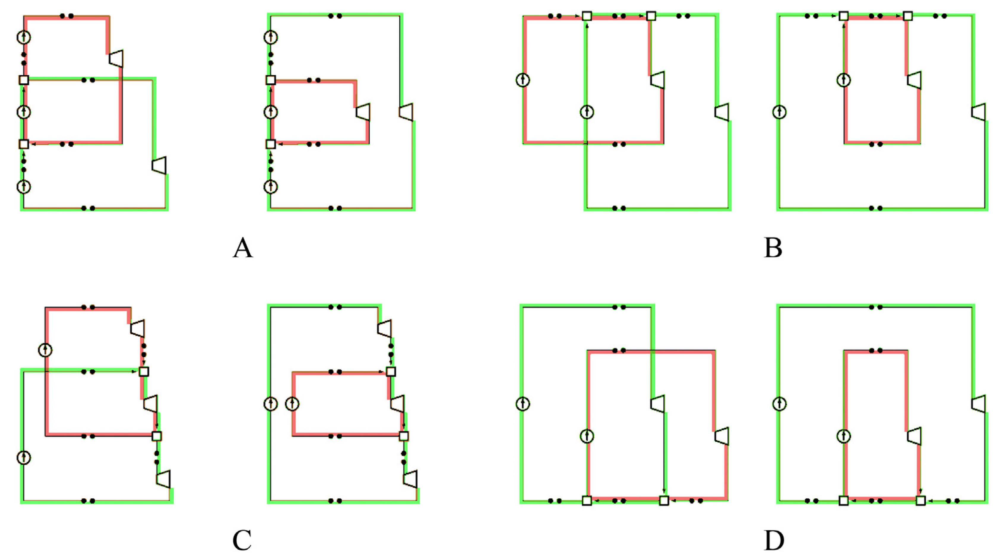
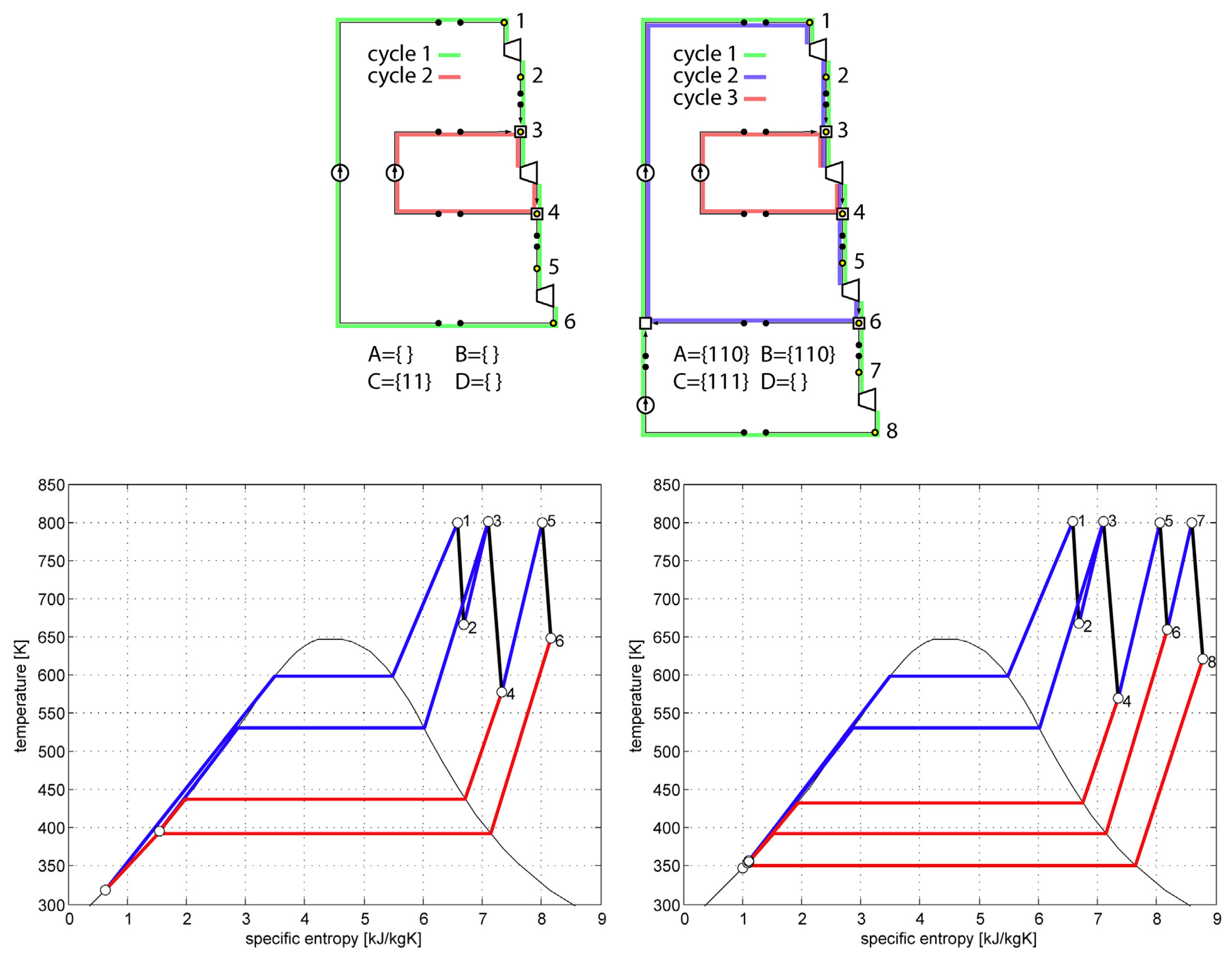
4.2. Superstructure-Free Synthesis

The fundamental problems of superstructure-based optimization remain: On the one hand, good alternatives (particularly, the optimal solution) might be excluded from the superstructure, while on the other hand, many meaningless or even infeasible alternatives may be considered. To overcome these problems, superstructure-free approaches apply metaheuristic algorithms to explore a practically unconstrained solution space, which is not limited a priori by a superstructure model.
In fact, back to 1970s, Stephanopoulos and Westerberg [231] have outlined a crucial view of the evolutionary synthesis: Given an initial structure and rules to systematically adjust the structure with small changes, an effective strategy applying the rules produces neighbor structures and thus “enumerates” all feasible structures, in which the optimal structure lies. Based on this idea, Seader and Westerberg [232] synthesized a simple separation sequence. Modern superstructure-free approaches apply metaheuristic algorithms, which perform “intelligently” and stochastically, thus many unpromising structures are not considered. Two-level hybrid algorithms are always involved: the upper level manipulates the structural representation (e.g., S-graph, see Section 4.1.1) for generating structurally feasible structures, while the lower-level evaluates the generated structures.
min σ   f ( s ( σ ) , d , o ) σ Σ ,
s . t .   min d , o f ( s ( σ ) , d , o ) ,
where the term of σ is solution structure evolved by mutation. The term of Σ is the space of all structure alternatives that can be possibly reached by repeated structural mutation. To exploit the bi-level formulation, the superstructure-free optimization employs a hybrid algorithm combining an evolutionary algorithm for the upper level with deterministic optimization for the lower level. The upper-level evolutionary algorithm generates structural alternatives s , i.e., units-selection and interconnections among the employed units, while each alternative generated by the upper level is then optimized deterministically in the lower level, i.e., identification of optimal sizing d and operation o of the employed units. The structural decisions s are not explicitly modeled in a superstructure, but the structures are evolved with the new structural alternatives σ generated by an evolutionary algorithm.
For HEN synthesis, Fraga [206] proposed a set of grammars for string representations to add heat exchangers and split streams. With a string rewriting system, the genetic algorithm can generate complex networks. Toffolo [233] proposed a more flexible graph representation, with which genetic algorithms were used to perform the insertion and deletion of the heat exchanger, and swaps of hot and cold sides of two heat exchangers. However, these approaches are tailored to HEN synthesis.
Wright et al. [234] performed both mutation and crossover to heating, ventilating and air conditioning system for an evolutionary synthesis. The mutation swaps two randomly selected components or their interconnections, while the crossover allows the offsprings inheriting structural properties and technical specifications from two parents either separately or in an equal measure. However, this approach is basically incapable of being extended to other applications.
Toffolo [235] proposed a hybrid algorithm, which is further developed as SYNTHSEP [236] approach for complete flowsheet synthesis of thermal power plants. The approach decomposes a thermal system into the heat transfer section and the remaining parts (basic configuration) by a heat separation decomposition [237]. The algorithm sequentially synthesizes the basic configuration by genetic algorithm and SQP, and the heat transfer section by pinch method.
Emmerich et al. [204] proposed an S-graph based genetic algorithm making total flowsheet synthesis of energy and process systems more flexible. A set of symmetric replacement rules for generating the closest neighboring structures are defined as minimal moves, such as insert a heater parallel to an existing heater or swap a by-product stream with a recycle stream. The minimal move mutation operator recognizes existing patterns, such as one component or a set of components, and replaces them with similar patterns according to the replacement rules; while the crossover operator recognizes and swaps the subsystems in the parents, which possess the same function and similar connection patterns. This approach has been applied to chemical process [204,238] and thermal power plant [239]; however, the major problem lies in the problem-specific replacement rules, which largely limit its extendibility. To cope with this problem, Voll et al. [240] and Wang et al. [241,242] further developed this approach by combing an energy conversion hierarchy (ECH), which allows for generic replacement rules.

4.3. Applications

4.3.1. Superstructure-Based Synthesis

The applications of superstructure-based concepts for various thermal power plants are summarized in Table 3. For these identified references, different types of structural representations were employed: decision tree, graph theory, predefined superstructure, algorithmically-generated superstructure of steam cycles with multiple pressure levels.
Regarding the use of decision tree, Hellermeier et al. [213] investigated the design synthesis of feedwater preheater train of thermal power plants via genetic and stochastic optimization techniques. The structural alternatives are represented by (modified) decision trees (as a type of superstructure) to consider the hierarchical parameter dependencies, and a set of rules are defined to find a feasible layout (a tuple of values of decision variables). Once the decision variables are selected, there will be a run through the decision tree with a set of predefined rules to collect and ensure the dependent variables for matching the chosen decision variables. Two solving strategies are tested and compared to cope with structural variables: (1) bi-level hierarchical method with the upper-level algorithms handling structural variables and the lower-level SQP algorithm addressing continuous variables, and (2) single-level evolutionary method with appropriately adapted genetic algorithms handling simultaneously structural and continuous variables. Two case studies with 8 and 26 discrete variables respectively are employed to compare the two solving strategies. It was found that, for both case studies, the one-level evolutionary algorithm performed slightly better with better objective value found and fewer iterations (computational time). The optimal system layouts found by both methods differed from each other. It was also concluded that varying plant layouts had a more prominent effect on the values of objective function than the optimization solving only continuous variables.
Regarding the use of graph theory, Grekas and Frangopoulos [200] employed nodes and edges to represent component and streams (connection), and stored the topology of the graphs as digraph of the data structure. The mathematical models of the components are automatically added to the optimization problem by object-oriented programming, once the components are used. With a parametric representation of component usage and connection, a plant layout can be automatically generated with the corresponding mathematical model formed. Then, binary trees for mass and energy balance as well as a digraph for pressure hierarchy are generated to introduce splitting ratios of mass and energy at each node and the pressure of each connection as decision variables to form a feasible process. The optimization is reported to be efficient, less than 5 min for the considered examples.
Regarding the use of predefined superstructure, it can be represented (i) directly coded via mathematical programming languages [201,202], e.g., AMPL and GAMS, which can easily form a graph with the set data type, or (ii) graphically in professional simulators, e.g., [208,243]. The directly-coded superstructure allows simultaneous solving of structural and continuous variables, if the component models and thermodynamic properties of material flows are properly formulated. While the graphical superstructure via simulators is usually integrated into a bi-level solving procedure, where the upper-level iteratively updates the value of decision variables and the lower-level forms a specific structure from the superstructure and employs the simulator to obtain the objective functions. The benefits of such bi-level optimization are efficient solving of nonlinear processes. In [202], a superstructure of gas-fired combined cycle was coded in GAMS and solved with the proposed LaGO solver, which generates a convex relaxation of the MINLP and applies a Branch and Cut algorithm to the convex relaxation. It was concluded that, for the optimal design of combined cycle, the focus should be set on the configuration of the steam cycle with the consideration of process steam extraction, which defined the complexity of the design problem. In [208,243] the superstructure of steam cycle considers up to 10 feedwater preheaters and a secondary steam turbine and was solved with differential evolution, which handles both the structural and continuous variables. The effects of temperature and pressure of main and reheat steam on the plant efficiency were investigated with the optimization of steam-extraction pressure and mass flowrate. Some design guidelines were found to support future plant design. The disadvantages of such predefined superstructure are mainly the poor extendibility and the risk of leaving many good alternatives out of consideration; therefore, there are no other applications in this category found for thermal power plants.
For the use of algorithmically-generated superstructure of steam cycle, the most representative and applied is the steam network routine continuously developed by the group of Industrial Process and Energy Systems Engineering at EPFL, following the original idea published in [244]. The steam network is a part of the flagship tool OSMOSE for the optimal conceptual design of industrial processes and energy systems. OSMOSE can flexibly plug-in customized energy technologies to be considered and have been applied to solve various optimization problems with multiple trade-off solutions, e.g., biomass utilization [247,248], energy storage systems [5,249]. The bi-level architecture of OSMOSE is given in Figure 7: The upper (master) level employs evolutionary algorithms to handle the nonlinear variables, with whose values the lower (slave) level prepares the input data with AMPL (AMPL coded superstructure and the corresponding mathematical model for mass and energy balance, utility selection and sizing, heat cascade calculation etc.) and solves the optimization regarding various objective functions (e.g., capital or operational expenses) with CPLEX or Gurobi. The objective values are returned to the upper level for solution comparison and selection. The advantages of OSMOSE platform include (1) easy coupling of professional simulators (e.g., Aspen Plus) to address complex processes, (2) allowing flowsheet decomposition/reuse and easy extension of technology (flowsheet) library, (3) integration of mathematically-formulated heat cascade calculation, (4) integer programming to consider optimal selection of utilities, (5) easy handling of multiple objective functions.
For the steam network implemented in OSMOSE, the superstructure of steam turbine network is generated based on the predefined pressure levels at the upper level: For any pressure level i, a steam turbine is added between the pressure level i and any lower pressure level j with the calculation of intensive parameters (temperature, pressure and enthalpy) for each pressure level. Sometimes, a steam cycle only allows steam expansion between two neighboring pressure levels, which can be readily considered. At each pressure level, steam can be heated up to a higher temperature before expanding to the lower pressure level, or can be extracted as process steam for other processes or providing heat for the steam cycle itself. With such a bi-level algorithm, the MINLP of steam-network synthesis is converted to MILP at the lower level. Therefore, the decision variables are pressure levels, superheating degree (steam temperature at each pressure levels), subcooling temperature of the condensation level at the upper level, and the use and sizes of steam turbines and steam extractions at the lower level. The synthesis of steam network can be solved together with the sequential synthesis of heat exchanger networks, developed in [250], which can yield a specific layout of thermal power plants. Internally, the flexibility and effectiveness of steam network have been tested and improved to investigate modern coal-fired power plants with CO2 capture technologies; however, there have been no published references coping with thermal power plants. The steam network can also be employed as a utility to enhance the process integration and has been adapted for organic Rankine cycle [245] and heat pumping network [246]. The computational effort of each run of the lower-level optimization is mainly due to (1) the evaluation of thermodynamic properties and (2) the solving of the MILP problem. Each run of the lower level for a steam cycle with 8 pressure levels would take several seconds and the whole optimization for both levels can take several hours with the time mostly consumed at the lower level.

4.3.2. Superstructure-Free Synthesis

For the superstructure-free synthesis of steam cycles, there are only two methods developed as mentioned before, i.e., the SYNTHSEP method [236,251] and the ECH-based method [241,242], as summarized in Table 4.
(1) The SYNTHSEP method
The SYNTHSEP method was developed on the basis of HEATSEP method [237], which disaggregates existing energy system configurations into elementary thermodynamic cycles and identifies temperatures that can be varied (decision variables) in the design optimization, as illustrated in Figure 8. The SYNTHSEP method is kind of reversed version of HEATSEP as a bottom-up procedure to generate optimized system configurations by aggregation of elementary thermodynamic cycles. An elementary thermodynamic cycle is composed of four elementary processes, i.e., compression, heating, expansion and cooling. Many elementary cycles can be combined to form a basic system configuration automatically, as illustrated in Figure 9 with 2 elementary cycles sharing one thermodynamic process. Once a basic configuration is generated with the introduced mixers and splitters, thermal cut (as shown in Figure 8 right) can be placed to consider heat integration.
A bi-level hybrid algorithm is employed to find the optimal configuration with design variables: the upper-level evolutionary algorithm searches the configuration space and generates candidate configurations, which is further evaluated by the lower level traditional algorithm with SQP. The lower level searches for the optimal value of the objective function(s) by varying the only mass flow rates of the two elementary cycles of the Basic System Configuration, under the heat transfer feasibility constraint in the associated black-box, as shown in Figure 8. Therefore, each solution ends up with the topology and the design parameters (the optimum values of the temperatures, pressures and mass flow rates at the boundaries of the heat transfer black-box). However, to form a complete flowsheet, heat exchanger network has to be designed according to the techniques suggested by pinch analysis.
The SYNTHSEP method has been applied to various optimization problems for (organic) Rankine cycles and steam cycles [235,236]. It has been illustrated that different configurations can be efficiently generated and optimized, e.g., Figure 10 for steam cycles.
(2) The ECH-based method
The advantage of the ECH-based method is that it handles heat exchangers simultaneously with the change of pressure levels, which is not handled in the SYNTHSEP method. The algorithmic generation of a specific plant structure is achieved according to the energy conversion hierarchy and six generic replacement rules to change the plant structure. An ECH classifies the energy conversion technologies and links the technologies with the technological functions and replacement rules, as illustrated in Figure 11 for thermal power plants. There are three levels in an ECH: The meta, function and technology levels. Nodes at the meta-level represent the replacement rules. Nodes at the technology level represent specific energy conversion technologies. The connecting nodes on the function level classify energy conversion technologies according to their main functions (solid line) and types of drive (dashed line). With the ECH, it can be clearly shown that which replacement rules are applicable to a considered technology. Six replacement and insertion rules are finalized in the ECH-based method for thermal power plants:
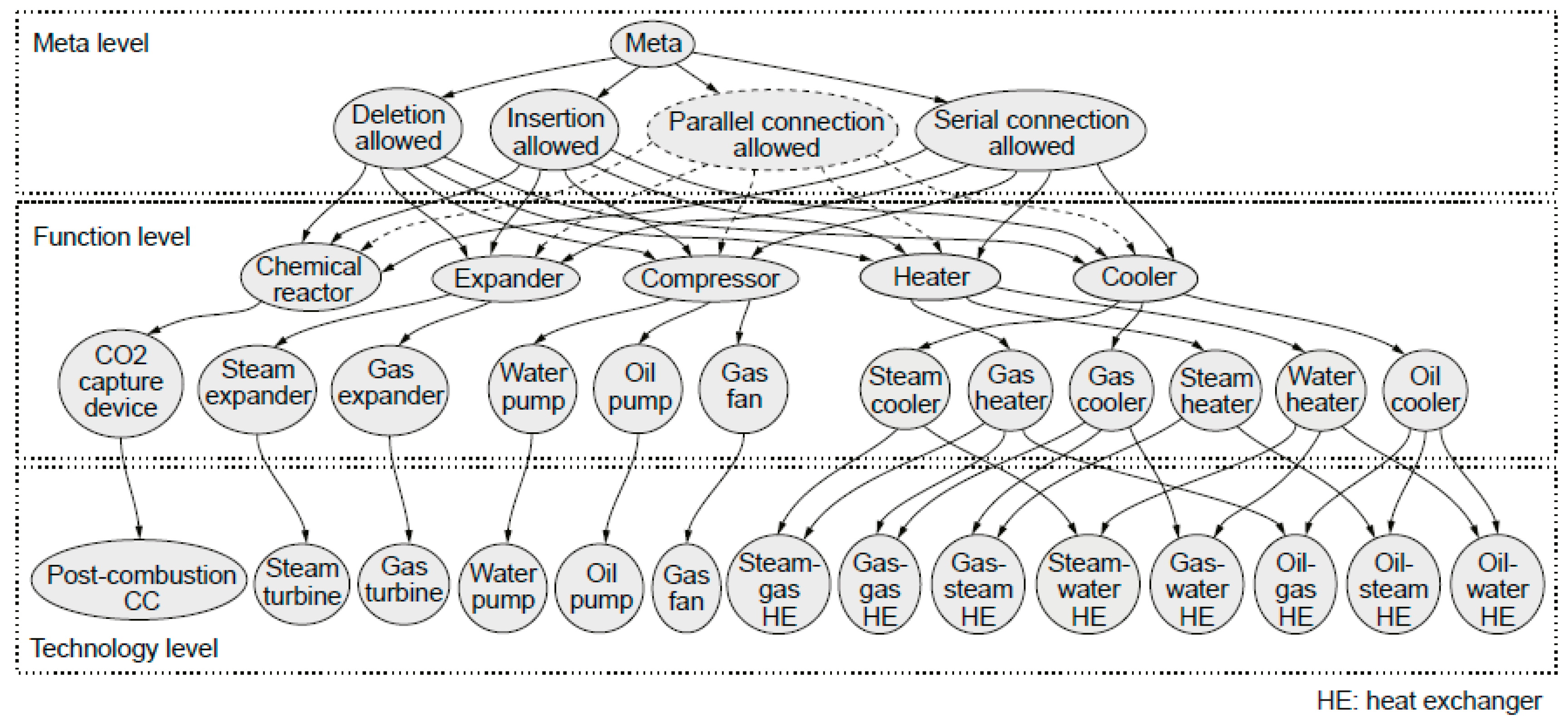
  • Remove one component with all of its interconnections.
  • Remove one component and short-circuit all of its interconnections.
  • Delete one component and insert another component.
  • Delete one component and insert a parallel connection of two other components.
  • Delete one component and insert a serial connection of two other components.
  • Insert one component by replacing the technology-related stream.
A bi-level solving procedure is employed: an evolutionary algorithm for the upper level with deterministic optimization for the lower level. The upper-level knowledge-integrated evolutionary algorithm, which is specifically tuned to flexibly integrate the ECH and replacement-insertion rules, generates structural alternatives from given structures, while each alternative generated by the upper level is then optimized deterministically in the lower level, i.e., GAMS used in [241,242].
The ECH-based method has been tested with simple Rankine cycles [241] and employed for solving complex problems [242]. It was found that the ECH-based method is an effective means to explore the design space, with a stable and high rate of the generation of structurally-feasible structures, even for highly complex problems. An example is given in Figure 12: starting from an initial flowsheet (a) with 4 feedwater preheaters and thermal efficiency of 46.49%, an optimal structure shown in (b) is featured with 8 feedwater preheaters, 2 reheaters, 2 de-superheaters, and a secondary turbine supplying steam for one feedwater preheater.
The computational effort is enormous due to the involvement of an evolutionary algorithm. For the complex problems tested in [242], the total time took several days. However, high-quality near-optimal solutions are generated already early in course of searching for the optimal solution. Also, the automatic structural generation without engineers’ attendance makes the large computation effort acceptable.

5. Multi-Objective Optimization

In Section 3 and Section 4, the optimization of energy systems is discussed with one objective function. However, many energy-system synthesis and design problems are multi-objective in nature, and they have conflicting objectives such as conversion efficiency, profit, cost of the system and environmental impacts [252]. A multi-objective optimization (MOO) problem is formulated as follows:
min x f ( x ) = ( f 1 ( x ) , f 2 ( x ) , , f k ( x ) ) T ,
s . t .   x X ,   g ( x ) 0 ,   h ( x ) = 0 ,
where the vector x   ( x R n ) denoting n independent decision variables in the feasible solution space X . The vector f represents k objective functions f k : R n R 1 . g ( x ) and h ( x ) are respectively inequality and equality constraints in the optimization problem.
Often, an MOO problem has many optimal solutions, known as non-dominated or Pareto-optimal solutions, which represent trade-offs among conflicting objectives. Two solutions are non-dominated to each other if the first solution is better than the second solution in at least one objective, and also the second solution is better than the first solution in at least one other objective. In other words, a solution becomes non-dominated or Pareto solution x ^ : (1) there is no other feasible solution x which is better in all objective functions,   f ( x ) f ( x ^ ) , (2) f i ( x ) < f i ( x ^ ) for at least one objective function.
There have been many algorithms developed to generate Pareto fronts: classical methods (e.g., weighted sum method [253], ϵ -constraint method [254] and normalized normal constraint method [255]) and metaheuristic methods based on population-based metaheuristics [256], such as genetic algorithm, genetic programming, evolutionary strategy, evolutionary programming and differential evolution [257,258]. These techniques support exploration at the beginning of the search and exploitation towards the end of the search.
This section is organized as follows: In Section 5.1, main-stream multi-objective optimization techniques are introduced with an emphasis on evolutionary algorithms. Then, Section 5.2 summarized the applications to thermal power plants with major contributions.

5.1. Multi-Objective Optimization Techniques

5.1.1. The Weighted Sum Method

MOO problems usually can be converted into single objective optimization (SOO) problems, which can be further solved using deterministic optimization methods such as branch-and-bound or sequential quadratic programming. The simplest technique for converting an MOO problem into an SOO problem is the weighted sum method:
min x   f ( x ) = i = 1 k w i · f i ( x ) ,
s . t .   x X ,   g ( x ) 0 ,   h ( x ) = 0 ,
Each objective f i is weighted by the positive weighting factors w i ( i = 1 k w i = 1 ) to form a super-objective f with inequality and equality constraints ( g and h ). The weighting factors can be adjusted via the preferences of decision makers or systematically, algorithmically to generate a series of small optimization problems, which can be solved one by one to find the Pareto solutions.

5.1.2. The ϵ -Constraint Method

In the ϵ -constraint method, one primary objective function is chosen, and other objective functions are converted to inequality constraints. It splits the objective function space into many sub-spaces by introducing additional inequality constraints from other objective functions. There could be many sub-spaces depending upon the ϵ values for other objective functions. Hence, ϵ -constraint method transforms a MOO problem into several SOO problems. The optimal solution of each SOO problem gives one Pareto solution. The generic ϵ -constraint method is formulated as follows:
min x   f ( x ) =   f i ( x ) ,   i = 1 ,   2 , k ,
s . t .   f j ( x ) ϵ j , p , j = 1 ,   2 , k ;   j i ;   p = 1 ,   2 , n ,
x X , g ( x ) 0 ,   h ( x ) = 0 .
For bi-objective optimization problem, a graphical representation of the ϵ -constraint method is shown in Figure 13. First of all, two anchor solutions ( μ ^ 1   a n d   μ ^ 2 ) are obtained by individually minimizing objective functions 1 and 2. Then, objective function space is divided into many subspaces by introducing bounds on objective function 1, e.g., ϵ 1 , ϵ 2 , ϵ 3 and ϵ n . The solution of each SOO problem gives one Pareto solution, e.g., s 1 for ϵ 1 and s 2 for ϵ 2 . The ϵ -constraint method performs effectively, and the quality of the Pareto front obtained depends on the slope (shape) of the Pareto front and the division of the objective space: The higher the front slope, the denser the division should be to obtain evenly-spread Pareto solutions (Figure 13). Hence, the value of ϵ has to be successively modified for each division of objective function space to find high-quality Pareto front. In case of more than two objectives, the selection of ϵ values becomes difficult to obtain a Pareto front with good spread.

5.1.3. The Normalized Normal Constraint Method

The normalized normal constraint (NNC) method [255] generates evenly-spaced Pareto solutions. NNC introduces normal to Utopia line to divide objective function space (Figure 14) instead of vertical lines in ϵ -constraint method (Figure 13). μ ^ 1 and μ ^ 2 are the anchor points obtained be successively minimizing objective functions 1 and 2, respectively. After obtaining the anchor points, Utopia line is defined by connecting both anchor points. The Utopia line is divided into several evenly spread points, i.e., μ 1 - μ 5 . NNC incorporates an additional inequality constraint by adding a normal line to the Utopia line, e.g., NU1 for μ 1 and NU2 for μ 2 . In other words, NNC method transforms a MOO problem into several SOO problems. For each SOO problem, the objective function space above the corresponding normal line is the feasible region, and remaining objective function space becomes the infeasible region. The optimal solution of each SOO problem is a Pareto solution, e.g., s 1 - s 5 . NNC method is able to generate a set of well-distributed Pareto solutions, even those on the non-convex regions of the Pareto front.

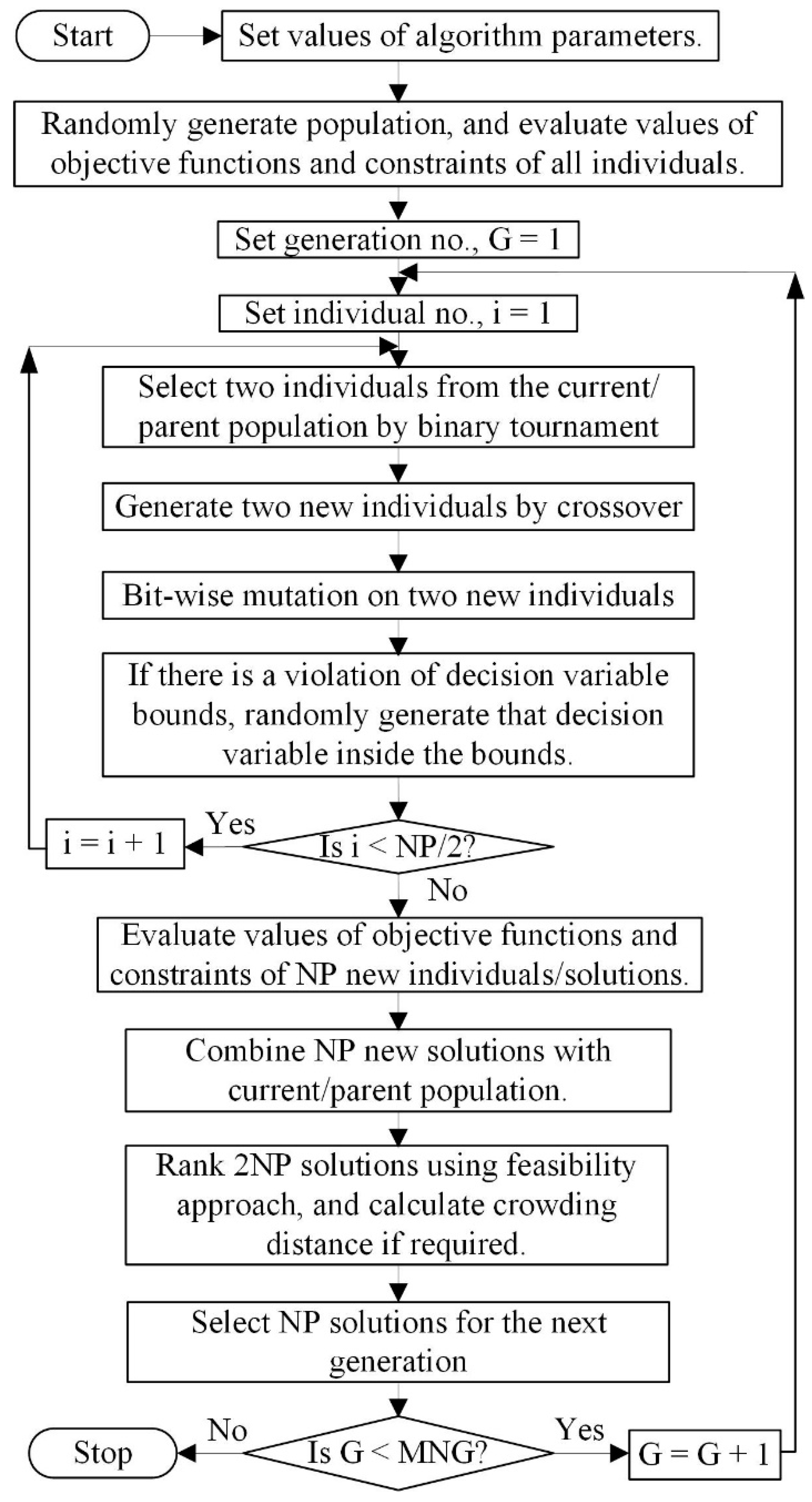
5.1.4. Evolutionary Multi-Objective Optimization Algorithms (EMOAs)

Among modern metaheuristics, evolutionary algorithms have a tremendous advantage in solving MOO problems. There are several EMOAs, such as the elitist non-dominated sorting genetic algorithm or NSGA-II [259], S-merit selection EMOA [260], the strength Pareto evolutionary algorithm or SPEA2 [261], the Pareto envelope-based selection algorithm or PESA [262], multi-objective genetic algorithm or MOGA-II [263], multi-objective messy GA or MOMGA [264]. In the following paragraphs, widely used NSGA-II is described in detail.
The NSGA-II algorithm works as described in Figure 15: initialization of population, selection of solution or individual for reproduction operation, crossover and mutation operations, individual selection for the next generation, and the search termination criterion. Initially, a population of NP individuals is randomly generated inside decision variables bounds. Then, two individuals from the current population are selected using binary tournament, and two new individuals are generated by crossover and mutation operations. If there is a decision variable violation for new individual, then that decision variable is randomly generated inside the bounds. In this way, new individuals are generated and then combined with the current/parent population. NSGA-II applies a fast non-dominated sorting of the combined population to assign non-domination ranks to all individuals or solutions. For each solution i in the combined population, the number of solutions that dominate solution i ( n i ) are calculated. Solution with n i = 0 are identified as the best Pareto front, F r . Then, the solutions in the best Pareto front are removed from the combined population, and next Pareto fronts ( F r + 1 , F r + 2 , etc.) are identified by repeating the procedure.
For constrained MOO problems, feasibility approach is used to rank the solutions in the combined population. If any of the following conditions is true, then solution i is dominating solution j :
  • Both solutions are feasible, and f i ( x ) < f j ( x ) for all objective functions.
  • Solution i is feasible and solution j is infeasible.
  • Both solutions are infeasible, but solution i has a smaller number of violated constraints (and lesser total absolute constraint violation if both have the same number of violated constraints) compared to solution j .
Solutions from the best Pareto fronts ( F r , F r + 1 , F r + 2 , etc.) are selected for the subsequent generation. If all solutions of a Pareto front cannot be selected, then crowding distances ( δ ) are calculated for each solution, and the least crowded solutions are selected to complete the new solutions for the next generation. NSGA-II calculates crowding distance of solutions for estimating their densities. For each objective function f m , the solutions in the Pareto front are sorted in a descending order, and solutions with the largest and smallest objective function values are specified with an infinity crowding distances. For each remaining solution i , its crowding distance with respect to the objective function f m is defined by its two neighbor solutions: δ m ( x i ) = f m ( x i 1 ) f m ( x i + 1 ) . Therefore, crowding distance of a solution with k objective functions: δ ( x i ) = m = 1 k δ m ( x i ) . Iterations are repeated for the maximum number of generations (MNG).

5.2. Applications

There have been many studies on MOO of thermal energy systems, which are mainly focused on the thermodynamic (e.g., energy and exergy efficiency, primary energy-saving ratio, thermal efficiency, electric efficiency, total avoidable exergy destruction rate), economic (e.g., NPV, total cost rate, annual gross profit, annualized cost per unit) and environmental (CO2 equivalent, pollution damage cost) objective functions. Table 5 summarizes recent MOO studies on the power plants or power-generation systems. The references mostly employ certain multi-objective optimization algorithm to solve specific problems without a significant methodology development. Considering the differences among the considered problems, these references are not be discussed in detail here but are summarized with the following findings:
(1) The trade-off
The trade-off between thermodynamic and economic objective functions usually follows the one illustrated in Figure 16. With an increase in plant efficiency, the fuel cost is reduced but the investment cost increases, which results in a V-shaped profile of total cost with an economic minimum point. The Pareto front starts from the economic minimum point and reaches the maximum efficiency point.
The thermodynamic and environmental objectives usually are not with a trade-off relationship, since increasing efficiency will reduce the fuel consumption, usually leading to lower emission, particularly for fossil-fuel based energy systems. However, trade-off may exist between the economic and environmental objectives following the fuel cost vs. efficiency (emission) as shown in Figure 16: the decrease in cost may possibly increase the pollutant emission, as revealed in [268].
(2) The algorithms and solution quality
As shown in Table 5, the dominating algorithms (over 80%) applied to energy systems are EA, due to the black-box evaluation of nonlinear objective functions and the smoothness of the Pareto fronts. For most cases, a sole evolutionary algorithm is enough to generate high-quality solutions; however, sometimes, the decision-making might be conservative to choose more stable sub-optimal solutions. In such a situation, mathematical programming methods are employed to effectively generate nearby solutions, e.g., by adding integer cut constraints (ICC) [268,276,280].
(3) Computational time
The EA is more effective for searching a Pareto optimal set and nearby solutions, while the ICC combined with the ε constraint is more time-consuming, since it needs to generate most solutions in the feasible space. However, if we only want to obtain a limited number of ordered solutions, then the ICC is powerful and fast [268]. The computational time for EA can be reduced by parallel computation, but not for the ICC method, since generating a new solution with ICC totally depends on previous ones consequently no possibility of using parallel computation [268].

6. Comparison and Perspectives

In the following, a straightforward comparison of the implementation of the identified methodologies to thermal power plants is given first and then future perspectives are provided as a further discussion.

6.1. Comparison of the Identified Methodologies

Considering the current activity and comprehensive impact of the introduced methodology, we highlight the following for thermal power plants: SPECO and advanced exergy-based analysis (analysis method), steam network in OSMOSE (superstructure-based synthesis), SYNTHSEP and ECH-based methods (superstructure-free synthesis). The features of these selected methods are compared in Table 6.

6.2. Future Perspectives

Three directions of future research on evaluation and optimization-based synthesis of thermal power plants are recommended: real-world designs and retrofits, evaluation and synthesis methodologies, and good modeling practice.

6.2.1. Real-World Optimal Designs and Retrofits

Usually, the grassroots design of energy systems is addressed but not incorporates off-design performances of all involved components. This is reasonable for single-purpose (product), single-source system, as all the employed components are set to operate under partial loads: higher efficiency at the design load would generally lead to higher efficiency at partial loads.
However, when new energy systems are synthesized for multiple products and/or multiple sources, or existing energy systems are expected to be further enhanced by introducing new technologies, the operation-level synthesis must be considered.
For thermal power plants, off-design models for a wide range of technologies, e.g., Stodola ellipse model [149,281] for large steam turbines, Rabek method for feedwater preheater [282], etc. Sound mathematical models to predict off-design performances are to be developed for different components.
A flexible system-level superstructure-free synthesis framework, which is capable of coping with those new challenges when introducing multiple technologies. This approach is expected to extend the range of its application. For thermal power plants, more available technologies can be included in the energy conversion hierarchy, for example, Organic Rankine Cycle [283], supercritical CO2 cycle [284], CO2 capture technologies [285,286], solar-thermal utilization technologies [287], energy storage [288,289], etc. Except for the grassroots design, optimal retrofits of thermal power can be solved as well by combining well-developed off-design models of all involved technologies.
The design and retrofits of energy systems must consider more realistic (structural) constraints and objective functions, to ensure that the obtained optimal or near-optimal solutions eventually can be valid for industrial applications. Unfortunately, practical constraints have not been compressively considered yet in most research papers. Specifically to thermal power plants, the steam-extraction pressure for de-aerator should be limited within the range from 5 to 15 bar [213] due to technical reasons; the pressures of steam extractions are not completely continuous but are constrained by the turbine design; the secondary turbine which supplies only one steam extractions is less likely to be implemented in real power plants; the cost functions of all components should be developed with more available industrial data or with the participation of industrial partners. Only when well-established objectives are optimized under reasonable real-world constraints could the number, size and operation mode of each component be well-constrained.

6.2.2. Evaluation and Synthesis Methodologies

Future perspectives on the methodology development concern mainly reasonable estimation approach for endogenous exergy destructions, effective utilization of valuable results from the exergy-based analysis, possible combination of analysis methods with automated synthesis approaches, and further algorithm enhancements of the automatic structural evolutions. A further discussion is given below:
(a) A more rational way of estimating endogenous exergy destructions
There are still some open fundamental problems for calculating endogenous exergy destructions. A drawback of the recently developed calculation method [95] (described in Section 2.3.2) is that, for complex systems, mass flow rates of the streams entering the considered component, whose endogenous exergy destruction is to be calculated, are difficult to determine, since the theoretically-operated components are treated as a reversible black box. In fact, the mass-flow relationships between the streams of the considered component and the black box are hard to establish reasonable, especially when the splitting and mixing of streams are presented in a flowsheet. Moreover, the fundamentals of the means of handling specific exergies of those streams flowing into the considered component have not been clearly described, particularly for complex systems with, e.g., heat-exchanger and steam-turbine trains.
(b) Adaptive structural evolution strategies
These strategies are expected to help further avoid the generation and evaluation of a number of meaningless structure alternatives. When using genetic algorithms to solve superstructure-based and superstructure-free problems, there are no fundamental differences in mutating which part of the structure. It is almost equivalently assumed that, before each evaluation of the generated structure, the change of any part of the structure would lead to the same effect on the objectives. However, different components, or more clearly, subsystems, have different impacts on the overall system performance. The subsystems, which present larger potentials for improving the objectives, should be given priority to be adjusted. Therefore, proper decomposition methods and adaptive evolution strategies should be developed or coupled to efficiently evolve the structure. For example, decompose the whole system into several subsystems ranked regarding their influences on the performance of the whole system. For another, evolve higher-rank subsystems and estimate their effects on the overall performance of the system. Consequently, frequent adjustments of the parts of the system structure that lead to only limited improvement of overall performance can be, to a large extent, suppressed. In addition, the decomposed subsystems, which are expected to be smaller, easy-to-solve subproblems out of the whole problem, require much fewer computation efforts to be optimized.
(c) Efficient identification of duplicate structures searched
Although many meaningless structural alternatives can be avoided in the superstructure-free approach, duplicate meaningful structures are frequently generated. The duplicate structures may lead to not only huge extra computational time to find the same optimal structure, but also a decrease in the diversity of the preserved solution structures.
Although a large number of meaningless structural alternatives can be avoided in the superstructure-free approach, duplicate meaningful structures are frequently generated. The duplicate structures may lead to not only huge extra computational time to find the same optimal structure, but also a decrease in the diversity of the preserved solution structures. For complex problems, e.g., cost-effective synthesis of thermal power plants, the average evaluation time of an individual structure can be long (over 20 s). The preserve of identical flowsheets can be suppressed in each mutation by discarding those offspring solutions with very similar objective values as the parent solution but generating an offspring solution with a different objective value. However, on the one hand, duplicate structures are distinguished only after the evaluation of the structures, thus it does not help reduce the total computation time; on the other hand, duplicate structural alternatives can still be frequently generated from two independent mutations. Effective algorithms are expected to efficiently identify whether the generated solution has been evaluated or not in the history of the current structural evolution. These algorithms would be quite favorable to further enhance the superstructure-free synthesis approach for synthesizing thermal power plants.
(d) Integration of analysis methods into system synthesis
There is still a large gap between different analysis methods and optimization-based synthesis of thermal systems. It is expected that the coupling of proper analysis methods would further improve the performance of automated synthesis approaches, particularly the optimization of structural alternatives. For example, the thermo-economic functional analysis [50] could formulate the objective functions in explicit relations with decision variables by the insights into the considered energy system. These reformulations of objective functions could lead to proper system decompositions and the removals of surplus intermediate variables and equations. Accordingly, the computational effort for optimizing the same structural alternative can be reduced. However, currently, these approaches are hardly applicable to complex problems and, most importantly, fundamentally, they can only support the optimal synthesis based on a predefined superstructure so far. There are challenges to automatically and properly reformulate the objective functions with respect to different system structures.
For the most widely used accounting methods, e.g., SPECO, few references have been published on employing this analysis information for the parametric optimization; while for structural improvements engineers’ expertise usually have to be integrated to judge which parts of the analyzed structure should be modified and how to modify. Thus, for automated optimization-based synthesis, these accounting methods should probably be employed to rank different subsystems for modification.
A far long way is ahead as well for the developing advanced exergy-based analysis to be a supportive method of synthesis approach. There have been no available references yet on how to reasonably use the information from the splitting of exergy destructions and costs for parametric and structural optimization.

6.2.3. Mathematical Modeling Practice

The bad mathematical formulation may evaluate feasible structures as infeasible solutions, good structures as bad solutions as the search procedure may be trapped at local optimums. Good modeling practice, particularly for NLP and MINLP, could help build efficient and sound formulations that can be solved much faster, easier with less possibility of being trapped locally. Various techniques are available for good model formulations, such as setting good initial values and bounds of all variables (including intermediate variables), properly scaling variables and equations, reformulations (piecewise/polynomial/separable approximations or even linearization) of nonlinear formulations, convexification of nonconvex formulations, etc. Note the reformulations of nonlinear or nonconvex equations may lead to the loss of a certain degree of accuracy or even unacceptable optimal solutions, thus they must be carefully developed and checked before replacing the original formulations.

7. Conclusions

System analysis, synthesis and optimization regarding various objective functions are the key leveler to enhance the performances of energy systems. For each topic, we first introduced the fundamentals and methodologies developed in the literature and then summarized their applications to thermal power plants. Considering current status of existing methodologies, we have emphasized and compared the following methods with more details: SPECO and advanced exergy-based analysis for system analysis, steam network for superstructure-based synthesis, and SYNTHSEP and ECH-based methods for superstructure-free synthesis.
  • For system analysis, the advanced exergy-based analyses aim at paving a step further above traditional exergy analysis to reveal the sources and avoidability of exergy destruction and costs within different components and their interactions. The related methods are still under development and remain several fundamental problems to be addressed, e.g., validation of the splits of exergy dissipation.
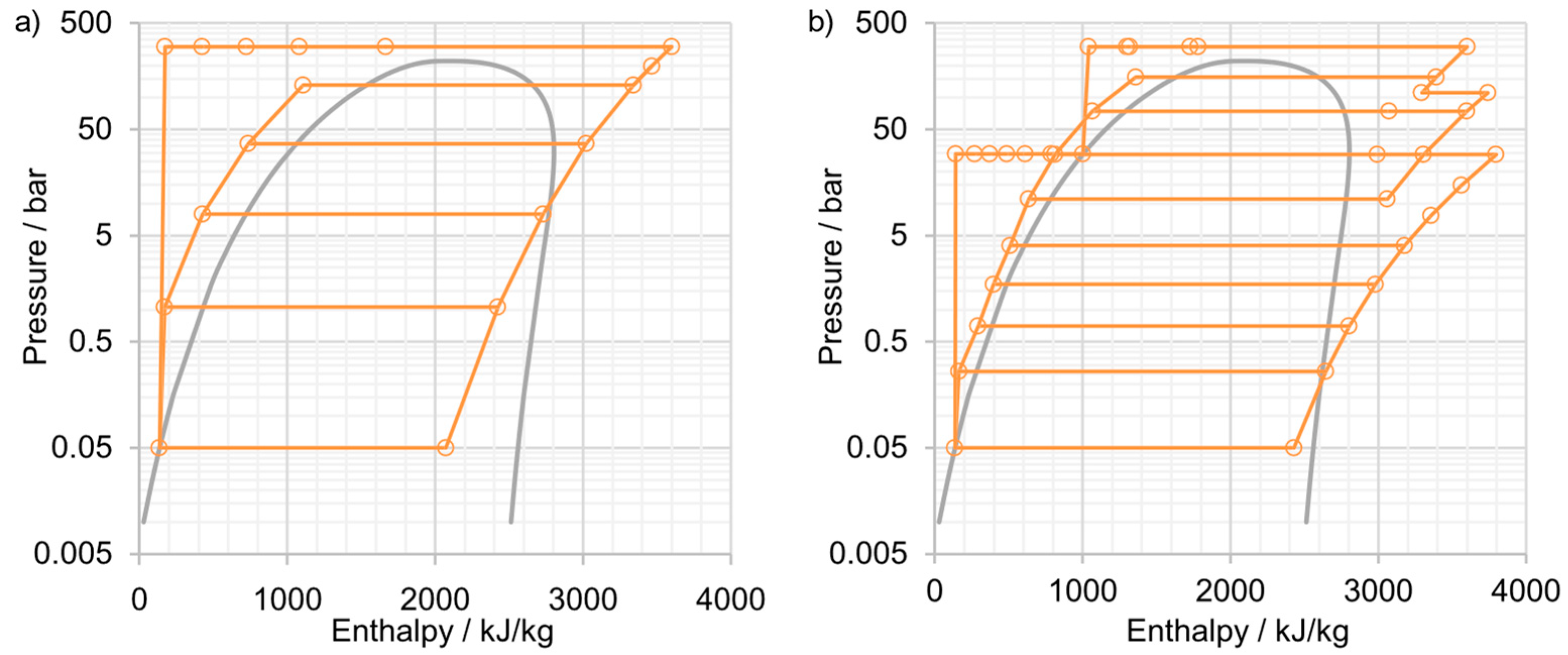
  • For superstructure-based synthesis, the steam network, incorporating algorithmic generation of the steam-cycle superstructure for a predefined number of pressure levels and bi-level hybrid solving algorithm (EA+MILP), is flexible to be employed as standalone thermal power plants or a utility for process integration. However, the method must combine with superstructure-based heat exchanger network for synthesizing complete flowsheets.
  • For superstructure-free synthesis, both SYNTHSEP and ECH-based method performs evolutionary structural alternation of given structures based on different concepts. The SYNTHSEP, not for complete flowsheet synthesis, employs elementary cycles and the share of multiple elementary cycles, which limits its use for other processes. The ECH-based method can perform total flowsheet synthesis and can be flexibly extended with well-defined ECH and component models. Both methods employ bi-level decomposition techniques combining EA and mathematical programming.
Future perspectives of methodology development and applications are summarized:
  • A straightforward comparison of these chosen methods on a common basis of a benchmarking problem should be made, since the applications given in literature aimed at solving specific optimization problems.
  • Three directions of method development and implementation are recommended: real-world designs and retrofits, further methodology development, particularly synthesis methodologies, and good modeling practice.

Author Contributions

L.W. structured the paper, reviewed major references cited and is the main author of the paper. Z.Y., S.S., A.M., T.-E.L. contributed to the writing of relevant sections. F.M. provided valuable comments and discussion. G.T. and Y.Y. provided supervision of the technical contents for L.W.’s doctoral thesis.

Funding

The authors, Z.Y. and Y.Y., received financial support from the National Nature Science Fund of China (51436006).

Acknowledgments

Special thanks to the editors, Andrea Lazzaretto and Andrea Toffolo, for the kind invitation, which encourages L.W. to complete the paper.

Conflicts of Interest

The authors declare no conflict of interest.

Nomenclature

DEdifferential evolution
EAevolutionary algorithm
ECHenergy conversion hierarchy
GDPgeneralized disjunctive programming
GRGgeneralized reduced gradient
HPThigh-pressure turbine
ICCInteger cut constraint
IPinteger programming
IPTintermedia pressure turbine
LPlinear programming
LPTlow-pressure turbine
MILPmixed integer linear programming
MINLPmixed integer nonlinear programming
MOOmulti-objective optimization
NLPnonlinear programming
NNCnormalized normal constraint
SOOsingle objective optimization
SPECOspecific exergy costing
SQPsuccessive quadratic programming
TRRtotal revenue requirement
E ˙ exergy flow, MW
d design variable
f objective function
f m objective function
F Pareto front
F r the best Pareto front
g inequality constraint
h equality constraint; or enthalpy, kJ/kg
m ˙ mass flow, kg/s
o operational variable
s structural variable
T temperature, ℃
( ν 1 · ν 2 )continuous nonconvex bilinear term
w weighting factor
x vector in the feasible solution space
X solution space
z variable to replace the bilinear term
Zinvestment cost, M$
Greek letters
Σ space of all structure alternatives
δ crowding distance
η efficiency
λ size of offspring population
σ solution structure evolved by mutation
μ size of parent population; or solution
μ ^ anchor solution
ϵ objective function
Subscripts and superscripts
Aaverage
absabsorption
AVavoidable
Ddestruction
ENendogenous
EXexogenous
Ffuel
i, j, kindex
Lloss
Nindependent decision variable
Pproduct
relrelease
UNunavoidable

References

  1. Sieminski, A. International Energy Outlook; Energy Information Administration (EIA): Washington, DC, USA, 2014.
  2. Iodice, P.; Senatore, A. Atmospheric pollution from point and diffuse sources in a National Interest Priority Site located in Italy. Energy Environ. 2016, 27, 586–596. [Google Scholar] [CrossRef]
  3. Iodice, P.; Adamo, P.; Capozzi, F.; Di Palma, A.; Senatore, A.; Spagnuolo, V.; Giordano, S. Air pollution monitoring using emission inventories combined with the moss bag approach. Sci. Total Environ. 2016, 541, 1410–1419. [Google Scholar] [CrossRef] [PubMed]
  4. Qazi, H.W.; Flynn, D. Synergetic frequency response from multiple flexible loads. Electr. Power Syst. Res. 2017, 145, 185–196. [Google Scholar] [CrossRef]
  5. Wang, L.; Pérez-Fortes, M.; Madi, H.; Diethelm, S.; Herle, J.V.; Maréchal, F. Optimal design of solid-oxide electrolyzer based power-to-methane systems: A comprehensive comparison between steam electrolysis and co-electrolysis. Appl. Energy 2018, 211, 1060–1079. [Google Scholar] [CrossRef]
  6. Jensen, S.H.; Graves, C.; Mogensen, M.; Wendel, C.; Braun, R.; Hughes, G.; Gao, Z.; Barnett, S.A. Correction: Large-scale electricity storage utilizing reversible solid oxide cells combined with underground storage of CO2 and CH4. Energy Environ. Sci. 2015, 8, 2471–2479. [Google Scholar] [CrossRef]
  7. Fukuda, Y. Development of Advanced Ultra Supercritical Fossil Power Plants in Japan: Materials and High Temperature Corrosion Properties. Mater. Sci. Forum 2010, 696, 236–241. [Google Scholar] [CrossRef]
  8. International Energy Agency (IEA). Technology Roadmap: High-Efficiency, Low-Emissions Coal-Fired Power Generation; International Energy Agency: Paris, France, 2012. [Google Scholar]
  9. Wang, L. Thermo-Economic Evaluation, Optimization and Synthesis of Large-Scale Coal-Fired Power Plants. Ph.D. Thesis, Technical University of Berlin, Berlin/Heidelberg, Germany, 2016. [Google Scholar]
  10. Rukes, B.; Taud, R. Status and perspectives of fossil power generation. Energy 2004, 29, 1853–1874. [Google Scholar] [CrossRef]
  11. Spliethoff, H. Steam Power Stations for Electricity and Heat Generation. In Power Generation from Solid Fuels; Springer: Berlin/Heidelberg, Germany, 2010; pp. 73–219. [Google Scholar]
  12. Silvestri, G.J., Jr.; Westinghouse Electric Corp. Boiler Feedpump Turbine Drive/Feedwater Train Arrangement. U.S. Patent 5,404,724, 11 April 1995. [Google Scholar]
  13. Blum, R.; Kjaer, S.; Bugge, J. Development of a pf fired high efficiency power plant AD700. In Proceedings of the Riso International Energy Conference: “Energy Solutions for Sustainable Development”, Roskilde, Denmark, 22–24 May 2007. [Google Scholar]
  14. Stępczyńska, K.; Kowalczyk, Ł.; Dykas, S.; Elsner, W. Calculation of a 900 MW conceptual 700/720°C coal-fired power unit with an auxiliary extraction-backpressure turbine. J. Power Technol. 2012, 92, 266–273. [Google Scholar]
  15. Eaves, J.; Palmer, F.D.; Wallace, J.; Wilson, S. The Value of Our Existing Coal Fleet: An Assessment of Measures to Improve Reliability & Efficiency While Reducing Emissions; The National Coal Council: Washington, DC, USA, 2014. [Google Scholar]
  16. Espatolero, S.; Cortés, C.; Romeo, L.M. Optimization of boiler cold-end and integration with the steam cycle in supercritical units. Appl. Energy 2010, 87, 1651–1660. [Google Scholar] [CrossRef]
  17. Karthikeyan, M.; Zhonghua, W.; Mujumdar, A.S. Low-rank coal drying technologies--Current status and new developments. Dry. Technol. 2009, 27, 403–415. [Google Scholar] [CrossRef]
  18. Turchi, C.S.; Langle, N.; Bedilion, R.; Libby, C. Solar-augment potential of US fossil-fired power plants. In Proceedings of the ASME 2011 5th International Conference on Energy Sustainability, Washington, DC, USA, 7–10 August 2011; pp. 641–651. [Google Scholar]
  19. Popov, D. An option for solar thermal repowering of fossil fuel fired power plants. Sol. Energy 2011, 85, 344–349. [Google Scholar] [CrossRef]
  20. Yang, Y.; Yan, Q.; Zhai, R.; Kouzani, A.; Hu, E. An efficient way to use medium-or-low temperature solar heat for power generation—Integration into conventional power plant. Appl. Therm. Eng. 2011, 31, 157–162. [Google Scholar] [CrossRef]
  21. Sansaniwal, S.K.; Sharma, V.; Mathur, J. Energy and exergy analyses of various typical solar energy applications: A comprehensive review. Renew. Sustain. Energy Rev. 2018, 82, 1576–1601. [Google Scholar] [CrossRef]
  22. Tsatsaronis, G. Thermodynamics and the Destruction of Resources; Cambridge University Press: New York, NY, USA, 2011; pp. 377–401. [Google Scholar]
  23. Moran, M.J.; Shapiro, H.N.; Boettner, D.D.; Bailey, M.B. Fundamentals of Engineering Thermodynamics, 7th ed.; John Wiley Sons: New York, NY, USA, 2010. [Google Scholar]
  24. Iodice, P.; Langella, G.; Amoresano, A.; Senatore, A. Comparative exergetic analysis of solar integration and regeneration in steam power plants. J. Energy Eng. 2017, 143, 04017042. [Google Scholar] [CrossRef]
  25. Cornelissen, R.L. Thermodynamics and Sustainable Development: The Use of Exergy Analysis and the Reduction of Irreversibility; Universiteit Twente: Enschede, The Netherlands, 1997. [Google Scholar]
  26. Tsatsaronis, G. Energy Economics and Management in Industry. In Energy Economics and Management in Industry; Pergamon Press: Oxford, UK, 1984; pp. 151–157. [Google Scholar]
  27. Kotas, T.J. The Exergy Method of Thermal Plant Analysis; Butterworth Publishers: Stoneham, MA, USA, 1985. [Google Scholar]
  28. Singh, O.K.; Kaushik, S. Energy and exergy analysis and optimization of Kalina cycle coupled with a coal fired steam power plant. Appl. Therm. Eng. 2013, 51, 787–800. [Google Scholar] [CrossRef]
  29. Sengupta, S.; Datta, A.; Duttagupta, S. Exergy analysis of a coal-based 210 MW thermal power plant. Int. J. Energy Res. 2007, 31, 14–28. [Google Scholar] [CrossRef]
  30. Aljundi, I.H. Energy and exergy analysis of a steam power plant in Jordan. Appl. Therm. Eng. 2009, 29, 324–328. [Google Scholar] [CrossRef]
  31. Erdem, H.H.; Akkaya, A.V.; Cetin, B.; Dagdas, A.; Sevilgen, S.H.; Sahin, B.; Teke, I.; Gungor, C.; Atas, S.; et al. Comparative energetic and exergetic performance analyses for coal-fired thermal power plants in Turkey. Int. J. Therm. Sci. 2009, 48, 2179–2186. [Google Scholar] [CrossRef]
  32. Ray, T.K.; Datta, A.; Gupta, A.; Ganguly, R. Exergy-based performance analysis for proper O&M decisions in a steam power plant. Energy Convers. Manag. 2010, 51, 1333–1344. [Google Scholar]
  33. Zhao, Z.; Su, S.; Si, N.; Hu, S.; Wang, Y.; Xu, J.; Jiang, L.; Chen, G.; Xiang, J. Exergy analysis of the turbine system in a 1000 MW double reheat ultra-supercritical power plant. Energy 2017, 119, 540–548. [Google Scholar] [CrossRef]
  34. Tsatsaronis, G. Thermodynamic Optimization of Complex Energy Systems. In Thermodynamic Optimization of Complex Energy Systems; Bejan, A., Mamut, E., Eds.; Springer: Amsterdam, The Netherlands, 1999; pp. 93–100. [Google Scholar]
  35. Tsatsaronis, G.; Winhold, M. Exergoeconomic analysis and evaluation of energy-conversion plants—I. Analysis of a coal-fired steam power plant. Energy 1985, 10, 81–94. [Google Scholar] [CrossRef]
  36. Tsatsaronis, G.; Winhold, M. Exergoeconomic analysis and evaluation of energy-conversion plants—II. A new general methodology. Energy 1985, 10, 69–80. [Google Scholar] [CrossRef]
  37. Tsatsaronis, G.; Pisa, J. Exergoeconomic evaluation and optimization of energy systems—Application to the CGAM problem. Energy 1994, 19, 287–321. [Google Scholar] [CrossRef]
  38. Tsatsaronis, G. Thermoeconomic analysis and optimization of energy systems. Prog. Energy Combust. Sci. 1993, 19, 227–257. [Google Scholar] [CrossRef]
  39. Lazzaretto, A.; Tsatsaronis, G. On the calculation of efficiencies and costs in thermal systems. In Proceedings of the ASME Advanced Energy Systems Division 1999, Nashville, TN, USA, 14–19 November 1999; American Society of Mechanical Engineers: New York, NY, USA, 1999; Volume 39, pp. 421–430. [Google Scholar]
  40. Lazzaretto, A.; Tsatsaronis, G. On the quest for objective equations in exergy costing. In Proceedings of the ASME Advanced Energy Systems Division 1997, Dallas, TX, USA, 16–21 November 1997; American Society of Mechanical Engineers: New York, NY, USA, 1997; Volume 37, pp. 197–210. [Google Scholar]
  41. Valero, A.; Lozano, M.; Muñoz, M. A general theory of exergy saving. III. Energy savings and thermodynamics. In Computer-Aided Engineering and Energy Systems Second Law Analysis and Modelling; Gaggioli, R., Ed.; American Society of Mechanical Engineers: New York, NY, USA, 1986; Volume 3, pp. 16–21. [Google Scholar]
  42. Valero, A.; Lozano, M.; Muñoz, M. A general theory of exergy saving. II. On the thermodynamic cost. In Computer-Aided Engineering and Energy Systems Second Law Analysis and Modelling; Gaggioli, R., Ed.; American Society of Mechanical Engineers: New York, NY, USA, 1986; Volume 3, pp. 9–15. [Google Scholar]
  43. Valero, A.; Lozano, M.; Muñoz, M. A general theory of exergy saving. I. On the exergetic cost. In Computer-Aided Engineering and Energy Systems Second Law Analysis and Modelling; Gaggioli, R., Ed.; American Society of Mechanical Engineers: New York, NY, USA, 1986; Volume 3, pp. 1–8. [Google Scholar]
  44. Valero, A.; Torres, C. Algebraic thermodynamic analysis of energy systems. In Proceedings of the Approaches to the Design and Optimization of Thermal Systems AES; American Society of Mechanical Engineers: New York, NY, USA, 1988; Volume 7, pp. 13–23. [Google Scholar]
  45. Valero, A.; Lozano, M.A.; Serra, L.; Torres, C. Application of the exergetic cost theory to the CGAM problem. Energy 1994, 19, 365–381. [Google Scholar] [CrossRef]
  46. Lozano, M.A.; Valero, A. Theory of the exergetic cost. Energy 1993, 18, 939–960. [Google Scholar] [CrossRef]
  47. Frangopoulos, C.A. Application of the thermoeconomic functional approach to the CGAM problem. Energy 1994, 19, 323–342. [Google Scholar] [CrossRef]
  48. Frangopoulos, C.A. Optimal Synthesis and Operation of Thermal Systems by the Thermoeconomic Functional Approach. ASME J. Eng. Gas Turb. Power 1992, 114, 707–714. [Google Scholar] [CrossRef]
  49. Frangopoulos, C.A. Functional decomposition for optimal design of complex thermal systems. Energy 1988, 13, 239–244. [Google Scholar] [CrossRef]
  50. Frangopoulos, C.A. Thermoeconomic Functional Analysis: A Method for Optimal Design or Improvement of Complex Thermal Systems; Georgia Institute of Technology: Atlanta, GA, USA, 1983. [Google Scholar]
  51. Von Spakovsky, M.R. A Practical Generalized Analysis Approach to the Optimal Thermoeconomic Design and Improvement of Real-World Thermal Systems; Georgia Institute of Technology: Atlanta, GA, USA, 1986. [Google Scholar]
  52. Von Spakovsky, M.R.; Evans, R.B. The Design and Performance Optimization of Thermal Systems. ASME J. Eng. Gas Turb. Power 1990, 112, 86–93. [Google Scholar] [CrossRef]
  53. Von Spakovsky, M.R. Application of engineering functional analysis to the analysis and optimization of the CGAM problem. Energy 1994, 19, 343–364. [Google Scholar] [CrossRef]
  54. Gaggioli, R.A.; El-Sayed, Y.M. A critical review of second law costing method--II: Calculus procedures. ASME J. Energy Resour. Technol. 1989, 111, 8–15. [Google Scholar] [CrossRef]
  55. Tsatsaronis, G.; Lin, L.; Pisa, J. Exergy Costing in Exergoeconomics. ASME J. Energy Resour. Technol. 1993, 115, 9–16. [Google Scholar] [CrossRef]
  56. Lazzaretto, A.; Tsatsaronis, G. SPECO: A systematic and general methodology for calculating efficiencies and costs in thermal systems. Energy 2006, 31, 1257–1289. [Google Scholar] [CrossRef]
  57. Kanoglu, M.; Ayanoglu, A.; Abusoglu, A. Exergoeconomic assessment of a geothermal assisted high temperature steam electrolysis system. Energy 2011, 36, 4422–4433. [Google Scholar] [CrossRef]
  58. Kalinci, Y.; Hepbasli, A.; Dincer, I. Exergoeconomic analysis of hydrogen production from plasma gasification of sewage sludge using specific exergy cost method. Int. J. Hydrogen Energy 2011, 36, 11408–11417. [Google Scholar] [CrossRef]
  59. Al-Sulaiman, F.A.; Dincer, I.; Hamdullahpur, F. Thermoeconomic optimization of three trigeneration systems using organic Rankine cycles: Part I--Formulations. Energy Convers. Manag. 2013, 69, 199–208. [Google Scholar] [CrossRef]
  60. Alkan, M.A.; Keçebaş, A.; Yamankaradeniz, N. Exergoeconomic analysis of a district heating system for geothermal energy using specific exergy cost method. Energy 2013, 60, 426–434. [Google Scholar] [CrossRef]
  61. Tsatsaronis, G.; Moran, M.J. Exergy-aided cost minimization. Energy Convers. Manag. 1997, 38, 1535–1542. [Google Scholar] [CrossRef]
  62. Cziesla, F.; Tsatsaronis, G. Iterative exergoeconomic evaluation and improvement of thermal power plants using fuzzy inference systems. Energy Convers. Manag. 2002, 43, 1537–1548. [Google Scholar] [CrossRef]
  63. Seyyedi, S.M.; Ajam, H.; Farahat, S. A new approach for optimization of thermal power plant based on the exergoeconomic analysis and structural optimization method: Application to the CGAM problem. Energy Convers. Manag. 2010, 51, 2202–2211. [Google Scholar] [CrossRef]
  64. Frangopoulos, C.A. Intelligent functional approach: A method for analysis and optimal synthesis-design-operation of complex systems. Int. J. Energy Environ. Econ. 1991, 4, 267–274. [Google Scholar]
  65. Hua, B.; Yin, Q.; Wu, G. Energy optimization through exergy-economic evaluation. ASME J. Energy Resour. Technol. 1989, 111, 148–153. [Google Scholar] [CrossRef]
  66. Hua, B.; Chen, Q.L.; Wang, P. A new exergoeconomic approach for analysis and optimization of energy systems. Energy 1997, 22, 1071–1078. [Google Scholar] [CrossRef]
  67. Valero, A.; Serra, L.; Lozano, M.A. Structural Theory of Thermoeconomics; ASME: New York, NY, USA, 1993; Volume 30, pp. 189–198. [Google Scholar]
  68. Torres, C.; Valero, A.; Rangel, V.; Zaleta, A. On the cost formation process of the residues. Energy 2008, 33, 144–152. [Google Scholar] [CrossRef]
  69. Seyyedi, S.M.; Ajam, H.; Farahat, S. A new criterion for the allocation of residues cost in exergoeconomic analysis of energy systems. Energy 2010, 35, 3474–3482. [Google Scholar] [CrossRef]
  70. Piacentino, A.; Cardona, E. Scope-Oriented Thermoeconomic analysis of energy systems. Part II: Formation Structure of Optimality for robust design. Appl. Energy 2010, 87, 957–970. [Google Scholar] [CrossRef]
  71. Piacentino, A.; Cardona, F. Scope-Oriented Thermoeconomic analysis of energy systems. Part I: Looking for a non-postulated cost accounting for the dissipative devices of a vapour compression chiller. Is it feasible? Appl. Energy 2010, 87, 943–956. [Google Scholar] [CrossRef]
  72. Banerjee, A.; Tierney, M.J.; Thorpe, R.N. Thermoeconomics, cost benefit analysis, and a novel way of dealing with revenue generating dissipative units applied to candidate decentralised energy systems for Indian rural villages. Energy 2012, 43, 477–488. [Google Scholar] [CrossRef]
  73. Paulus, D.M.; Tsatsaronis, G. Auxiliary equations for the determination of specific exergy revenues. Energy 2006, 31, 3235–3247. [Google Scholar] [CrossRef]
  74. Cardona, E.; Piacentino, A. A new approach to exergoeconomic analysis and design of variable demand energy systems. Energy 2006, 31, 490–515. [Google Scholar] [CrossRef]
  75. Kelly, S. Energy Systems Improvement based on Endogenous and Exogenous Exergy Destruction; Technische Universit at Berlin: Berlin/Heidelberg, Germany, 2008. [Google Scholar]
  76. Kelly, S.; Tsatsaronis, G.; Morosuk, T. Advanced exergetic analysis: Approaches for splitting the exergy destruction into endogenous and exogenous parts. Energy 2009, 34, 384–391. [Google Scholar] [CrossRef]
  77. Tsatsaronis, G.; Morosuk, T. A General Exergy-Based Method for Combining a Cost Analysis with an Environmental Impact Analysis: Part I--Theoretical Development. ASME Conf. Proc. 2008, 2008, 453–462. [Google Scholar]
  78. Gaggioli, R.; Reini, M. Panel I: Connecting 2nd Law Analysis with Economics, Ecology and Energy Policy. Entropy 2014, 16, 3903–3938. [Google Scholar] [CrossRef] [Green Version]
  79. Rashidi, J.; Yoo, C.K. Exergetic and exergoeconomic studies of two highly efficient power-cooling cogeneration systems based on the Kalina and absorption refrigeration cycles. Appl. Therm. Eng. 2017, 124, 1023–1037. [Google Scholar] [CrossRef]
  80. Sahin, A.Z.; Al-Sharafi, A.; Yilbas, B.S.; Khaliq, A. Overall performance assessment of a combined cycle power plant: An exergo-economic analysis. Energy Convers. Manag. 2016, 116, 91–100. [Google Scholar] [CrossRef]
  81. Ahmadzadeh, A.; Salimpour, M.R.; Sedaghat, A. Thermal and exergoeconomic analysis of a novel solar driven combined power and ejector refrigeration (CPER) system. Int. J. Refrig. 2017, 83, 143–156. [Google Scholar] [CrossRef]
  82. Baghsheikhi, M.; Sayyaadi, H. Real-time exergoeconomic optimization of a steam power plant using a soft computing-fuzzy inference system. Energy 2016, 114, 868–884. [Google Scholar] [CrossRef]
  83. Wang, L.; Yang, Y.; Dong, C.; Yang, Z.; Xu, G.; Wu, L. Exergoeconomic Evaluation of a Modern Ultra-Supercritical Power Plant. Energies 2012, 5, 3381–3397. [Google Scholar] [CrossRef] [Green Version]
  84. Cziesla, F.; Tsatsaronis, G.; Gao, Z. Avoidable thermodynamic inefficiencies and costs in an externally fired combined cycle power plant. Energy 2006, 31, 1472–1489. [Google Scholar] [CrossRef]
  85. Yang, Y.; Wang, L.; Dong, C.; Xu, G.; Morosuk, T.; Tsatsaronis, G. Comprehensive exergy-based evaluation and parametric study of a coal-fired ultra-supercritical power plant. Appl. Energy 2013, 112, 1087–1099. [Google Scholar] [CrossRef]
  86. Tsatsaronis, G.; Park, M.-H. On avoidable and unavoidable exergy destructions and investment costs in thermal systems. Energy Convers. Manag. 2002, 43, 1259–1270. [Google Scholar] [CrossRef]
  87. Morosuk, T.; Tsatsaronis, G. Advanced exergy analysis for chemically reacting systems—Application to a simple open gas-turbine system. Int. J. Thermophys. 2009, 12, 105–111. [Google Scholar]
  88. Morosuk, T.; Tsatsaronis, G. Advanced exergetic evaluation of refrigeration machines using different working fluids. Energy 2009, 34, 2248–2258. [Google Scholar] [CrossRef]
  89. Tsatsaronis, G.; Morosuk, T. Advanced exergetic analysis of a novel system for generating electricity and vaporizing liquefied natural gas. Energy 2010, 35, 820–829. [Google Scholar] [CrossRef]
  90. Petrakopoulou, F.; Tsatsaronis, G.; Morosuk, T.; Carassai, A. Advanced Exergoeconomic Analysis Applied to a Complex Energy Conversion System. ASME J. Eng. Gas Turb. Power 2011, 134, 243–250. [Google Scholar]
  91. Morosuk, T.; Tsatsaronis, G. Exergoeconomic evaluation of refrigeration machines based on avoidable endogenous and exogenous costs. In Proceedings of the 20th International Conference on Efficiency, Cost, Optimization, Simulation and Environmental Impact of Energy Systems, Padova, Italy, 25–28 June 2007; pp. 1459–1467. [Google Scholar]
  92. Morosuk, T.; Tsatsaronis, G. A new approach to the exergy analysis of absorption refrigeration machines. Energy 2008, 33, 890–907. [Google Scholar] [CrossRef]
  93. Tsatsaronis, G.; Kelly, S.O.; Morosuk, T.V. Endogenous and exogenous exergy destruction in thermal systems. In Proceedings of the ASME 2006 International Mechanical Engineering Congress and Exposition, Chicago, IL, USA, 5–10 November 2006; pp. 311–317. [Google Scholar]
  94. Tsatsaronis, G.; Morosuk, T.; Kelly, S. Approaches for Splitting the Exergy Destruction into Endogenous and Exogenous Parts. In Proceedings of the 5th Workshop Advances in Energy Studies, Porto Venere, Italy, 12–16 September 2006; pp. 12–16. [Google Scholar]
  95. Penkuhn, M.; Tsatsaronis, G. A decomposition method for the evaluation of component interactions in energy conversion systems for application to advanced exergy-based analyses. Energy 2017, 133, 388–403. [Google Scholar] [CrossRef]
  96. Sorgenfrei, M. Analysis of IGCC-Based Plants with Carbon Capture for an Efficient and Flexible Electric Power Generation; Technical University of Berlin: Berlin/Heidelberg, Germany, 2016. [Google Scholar]
  97. Kaushik, S.C.; Reddy, V.S.; Tyagi, S.K. Energy and exergy analyses of thermal power plants: A review. Renew. Sustain. Energy Rev. 2011, 15, 1857–1872. [Google Scholar] [CrossRef]
  98. Zhu, Y.; Zhai, R.; Peng, H.; Yang, Y. Exergy destruction analysis of solar tower aided coal-fired power generation system using exergy and advanced exergetic methods. Appl. Therm. Eng. 2016, 108, 339–346. [Google Scholar] [CrossRef]
  99. Ertesvåg, I.S.; Kvamsdal, H.M.; Bolland, O. Exergy analysis of a gas-turbine combined-cycle power plant with precombustion CO2 capture. Energy 2005, 30, 5–39. [Google Scholar] [CrossRef]
  100. Reddy, V.S.; Kaushik, S.C.; Tyagi, S.K. Exergetic analysis and performance evaluation of parabolic trough concentrating solar thermal power plant (PTCSTPP). Energy 2012, 39, 258–273. [Google Scholar] [CrossRef]
  101. Xu, C.; Wang, Z.; Li, X.; Sun, F. Energy and exergy analysis of solar power tower plants. Appl. Therm. Eng. 2011, 31, 3904–3913. [Google Scholar] [CrossRef]
  102. Hofmann, M.; Tsatsaronis, G. Comparative exergoeconomic assessment of coal-fired power plants – Binary Rankine cycle versus conventional steam cycle. Energy 2018, 142, 168–179. [Google Scholar] [CrossRef]
  103. Petrakopoulou, F. Comparative Evaluation of Power Plants with CO2 Capture: Thermodynamic, Economic and Environmental Performance; Technical University of Berlin: Berlin/Heidelberg, Germany, 2011. [Google Scholar]
  104. Petrakopoulou, F.; Boyano, A.; Cabrera, M.; Tsatsaronis, G. Exergoeconomic and exergoenvironmental analyses of a combined cycle power plant with chemical looping technology. Int. J. Greenh. Gas Control 2011, 5, 475–482. [Google Scholar] [CrossRef]
  105. Petrakopoulou, F.; Tsatsaronis, G.; Morosuk, T. Advanced Exergoenvironmental Analysis of a Near-Zero Emission Power Plant with Chemical Looping Combustion. Environ. Sci. Technol. 2012, 46, 3001–3007. [Google Scholar] [CrossRef] [PubMed]
  106. Petrakopoulou, F.; Tsatsaronis, G.; Morosuk, T.; Carassai, A. Conventional and advanced exergetic analyses applied to a combined cycle power plant. Energy 2012, 41, 146–152. [Google Scholar] [CrossRef]
  107. Wang, L.; Yang, Y.; Morosuk, T.; Tsatsaronis, G. Advanced Thermodynamic Analysis and Evaluation of a Supercritical Power Plant. Energies 2012, 5, 1850–1863. [Google Scholar] [CrossRef] [Green Version]
  108. Wang, L.; Fu, P.; Wang, N.; Morosuk, T.; Yang, Y.; Tsatsaronis, G. Malfunction diagnosis of thermal power plants based on advanced exergy analysis: The case with multiple malfunctions occurring simultaneously. Energy Convers. Manag. 2017, 148, 1453–1467. [Google Scholar] [CrossRef]
  109. Fu, P.; Wang, N.; Wang, L.; Morosuk, T.; Yang, Y.; Tsatsaronis, G. Performance degradation diagnosis of thermal power plants: A method based on advanced exergy analysis. Energy Convers. Manag. 2016, 130, 219–229. [Google Scholar] [CrossRef]
  110. Açıkkalp, E.; Aras, H.; Hepbasli, A. Advanced exergy analysis of an electricity-generating facility using natural gas. Energy Convers. Manag. 2014, 82, 146–153. [Google Scholar] [CrossRef]
  111. Gökgedik, H.; Yürüsoy, M.; Keçebaş, A. Improvement potential of a real geothermal power plant using advanced exergy analysis. Energy 2016, 112, 254–263. [Google Scholar] [CrossRef]
  112. Petrakopoulou, F.; Tsatsaronis, G.; Morosuk, T. Evaluation of a power plant with chemical looping combustion using an advanced exergoeconomic analysis. Sustain. Energy Technol. Assess. 2013, 3, 9–16. [Google Scholar] [CrossRef]
  113. Wang, L.; Yang, Y.; Dong, C.; Xu, G. Improvement and primary application of theory of fuel specific consumption. Zhongguo Dianji Gongcheng Xuebao (Proc. Chin. Soc. Electr. Eng.) 2012, 32, 16–21. [Google Scholar]
  114. Wang, L.; Wu, L.; Xu, G.; Dong, C.; Yang, Y. Calculation and analysis of energy consumption interactions in thermal systems of large-scale coal-fired steam power generation units. Zhongguo Dianji Gongcheng Xuebao (Proc. Chin. Soc. Electr. Eng.) 2012, 32, 9–14. [Google Scholar]
  115. Manesh, M.K.; Navid, P.; Marigorta, A.B.; Amidpour, M.; Hamedi, M. New procedure for optimal design and evaluation of cogeneration system based on advanced exergoeconomic and exergoenvironmental analyses. Energy 2013, 59, 314–333. [Google Scholar] [CrossRef]
  116. Tsatsaronis, G.; Morosuk, T. Understanding the Formation of Costs and Environmental Impacts Using Exergy-Based Methods. Energy Security and Development; Springer: Berlin/Heidelberg, Germany, 2015; pp. 271–291. [Google Scholar]
  117. Bolatturk, A.; Coskun, A.; Geredelioglu, C. Thermodynamic and exergoeconomic analysis of Çayırhan thermal power plant. Energy Convers. Manag. 2015, 101, 371–378. [Google Scholar] [CrossRef]
  118. Frangopoulos, C.A. Methods of energy systems optimization. In Summer school. In Proceedings of the Summer School: Optimization of Energy Systems and Processes, Gliwice, Poland, 24–27 June 2003. [Google Scholar]
  119. Glover, F.; Kochenberger, G.A. Handbook of Metaheuristics; Springer: Berlin/Heidelberg, Germany, 2003. [Google Scholar]
  120. Uhlenbruck, S.; Lucas, K. Exergy-Aided Cost Optimization Using Evolutionary Algorithm. Int. J. Appl. Thermodyn. 2000, 3, 121–127. [Google Scholar]
  121. Nocedal, J.; Wright, S. Numerical Optimization, 2rd ed.; Springer: New York, NY, USA, 2006. [Google Scholar]
  122. Biegler, L.T.; Grossmann, I.E. Retrospective on optimization. Comput. Chem. Eng. 2004, 28, 1169–1192. [Google Scholar] [CrossRef] [Green Version]
  123. Grossmann, I.E.; Biegler, L.T. Part II. Future perspective on optimization. Comput. Chem. Eng. 2004, 28, 1193–1218. [Google Scholar] [CrossRef] [Green Version]
  124. Floudas, C.A.; Gounaris, C.E. A review of recent advances in global optimization. J. Glob. Optim. 2009, 45, 3–38. [Google Scholar] [CrossRef]
  125. More, J.; Wild, S. Benchmarking Derivative-Free Optimization Algorithms. SIAM J. Optim. 2009, 20, 172–191. [Google Scholar] [CrossRef] [Green Version]
  126. Rios, L.M.; Sahinidis, N.V. Derivative-free optimization: A review of algorithms and comparison of software implementations. J. Glob. Optim. 2013, 56, 1247–1293. [Google Scholar] [CrossRef]
  127. Drud, A. CONOPT Documentation; ARKI Consulting and Development A/S: Bagsvaerd, Denmark, 2004. [Google Scholar]
  128. Nocedal, J.; Wright, S. Conjugate Gradient Methods; Springer: Berlin/Heidelberg, Germany, 2006. [Google Scholar]
  129. Nesterov, Y.; Nemirovskii, A.; Ye, Y. Interior-Point Polynomial Algorithms in Convex Programming; SIAM: Philadelphia, PA, USA, 1994. [Google Scholar]
  130. Matthias, K. On the Complexity of Nonlinear Mixed-Integer Optimization; Mixed Integer Nonlinear Programming; Springer: Berlin/Heidelberg, Germany, 2012; pp. 533–557. [Google Scholar]
  131. Bonami, P.; Kilincc, M.; Linderoth, J. Algorithms and Software for Convex Mixed Integer Nonlinear Programs; Mixed Integer Nonlinear Programming; Springer: Berlin/Heidelberg, Germany, 2012; pp. 1–39. [Google Scholar]
  132. Grossmann, I.E.; Guillén-Gosálbez, G. Scope for the application of mathematical programming techniques in the synthesis and planning of sustainable processes. Comput. Chem. Eng. 2010, 34, 1365–1376. [Google Scholar] [CrossRef] [Green Version]
  133. Grossmann, I.; Ruiz, J. Generalized Disjunctive Programming: A Framework for Formulation and Alternative Algorithms for MINLP Optimization. In The IMA Volumes in Mathematics and Its Applications; Lee, J., Leyffer, S., Eds.; Springer: New York, NY, USA, 2012; pp. 93–115. [Google Scholar]
  134. Grossmann, I.E.; Trespalacios, F. Systematic modeling of discrete-continuous optimization models through generalized disjunctive programming. AIChE J. 2013, 59, 3276–3295. [Google Scholar] [CrossRef]
  135. Vecchietti, A.; Grossmann, I.E. LOGMIP: A disjunctive 0--1 non-linear optimizer for process system models. Comput. Chem. Eng. 1999, 23, 555–565. [Google Scholar] [CrossRef]
  136. Voll, P. Automated Optimization-Based Synthesis of Distributed Energy Supply Systems; RWTH Aachen Univeristy: Aachen, Germany, 2014. [Google Scholar]
  137. Beyer, H.G.; Schwefel, H.P. Evolution strategies—A comprehensive introduction. Nat. Comput. 2002, 1, 3–52. [Google Scholar] [CrossRef]
  138. Deb, K.; Pratap, A.; Agarwal, S.; Meyarivan, T. A fast and elitist multiobjective genetic algorithm: NSGA-II. IEEE Trans. Evol. Comput. 2002, 6, 182–197. [Google Scholar] [CrossRef] [Green Version]
  139. Storn, R.; Price, K. Differential evolution--A simple and efficient heuristic for global optimization over continuous spaces. J. Glob. Optim. 1997, 11, 341–359. [Google Scholar] [CrossRef]
  140. Wagner, W.; Cooper, J.R.; Dittmann, A.; Kijima, J.; Kretzschmar, H.J.; Kruse, A. The IAPWS Industrial Formulation 1997 for the Thermodynamic Properties of Water and Steam. ASME J. Eng. Gas Turb. Power 2000, 122, 150–184. [Google Scholar] [CrossRef]
  141. Savola, T. Modeling Biomass-Fuelled Small-Scale CHP Plants for Process Synthesis and Optimization; Helsinki University of Technology: Espoo, Finland, 2007. [Google Scholar]
  142. Angira, R.; Babu, B.V. Optimization of process synthesis and design problems: A modified differential evolution approach. Chem. Eng. Sci. 2006, 61, 4707–4721. [Google Scholar] [CrossRef]
  143. Luo, X.; Zhang, B.; Chen, Y.; Mo, S. Modeling and optimization of a utility system containing multiple extractions steam turbines. Energy 2011, 36, 3501–3512. [Google Scholar] [CrossRef]
  144. Manassaldi, J.I.; Mussati, S.F.; Scenna, N.A.J. Optimal synthesis and design of Heat Recovery Steam Generation (HRSG) via mathematical programming. Energy 2011, 36, 475–485. [Google Scholar] [CrossRef]
  145. Judes, M. MINLP Optimization of Design and Steady-State Operation of Power Plants Considering Several Operating Points; Technical University of Berlin: Berlin/Heidelberg, Germany, 2009. [Google Scholar]
  146. TILMedia Suite. Available online: https://www.tlk-thermo.com/index.php/en/tilmedia-suite (accessed on 26 December 2018).
  147. Freesteam. Available online: http://freesteam.sourceforge.net/ (accessed on 26 December 2018).
  148. Pacherneggm, S.J. A Closer Look at the Willans-Line; SAE: Troy, MI, USA, 1969. [Google Scholar]
  149. Mavromatis, S.P.; Kokossis, A.C. Hardware composites: A new conceptual tool for the analysis and optimisation of steam turbine networks in chemical process industries: Part II: Application to operation and design. Chem. Eng. Sci. 1998, 53, 1435–1461. [Google Scholar] [CrossRef]
  150. Cooke, D.H. Modeling of Off-Design Multi-Stage Turbine Pressures by Stodola’s Ellipse; Energy Incoportated (PEPSE) User’s Group Meeting: Richmond, VA, USA, 1983. [Google Scholar]
  151. Paterson, W.R. A replacement for the logarithmic mean. Chem. Eng. Sci. 1984, 39, 1635–1636. [Google Scholar] [CrossRef]
  152. Drud, A.S. CONOPT—A large-scale GRG code. ORSA J. Comput. 1994, 6, 207–216. [Google Scholar] [CrossRef]
  153. Fair Isaac Corporation (FICO). XPRESS Optimization Suite: MIP Formulations and Linearizations; Fair Isaac Corporation: San Jose, CA, USA, 2009. [Google Scholar]
  154. Tomlin, J.A. Special Ordered Sets and an Application to Gas Supply Operations Planning; Mathematical Programming; Springer: Berlin/Heidelberg, Germany, 1988; Volume 42, pp. 69–84. [Google Scholar]
  155. Tsoukalas, A.; Mitsos, A. Multivariate mccormick relaxations. J. Glob. Optim. 2014, 59, 633–662. [Google Scholar] [CrossRef]
  156. Haywood, R.W. A generalized analysis of the regenerative steam cycle for a finite number of heaters. Proc. Inst. Mech. Eng. 1949, 161, 157–164. [Google Scholar] [CrossRef]
  157. Weir, C.D. Optimization of heater enthalpy rises in feed-heating trains. Proc. Inst. Mech. Eng. 1960, 174, 769–796. [Google Scholar] [CrossRef]
  158. Espatolero, S.; Romeo, L.M.; Cortés, C. Efficiency improvement strategies for the feedwater heaters network designing in supercritical coal-fired power plants. Appl. Therm. Eng. 2014, 73, 449–460. [Google Scholar] [CrossRef]
  159. Uche, J.; Serra, L.; Valero, A. Thermoeconomic optimization of a dual-purpose power and desalination plant. Desalination 2001, 136, 147–158. [Google Scholar] [CrossRef]
  160. Xiong, J.; Zhao, H.; Zhang, C.; Zheng, C.; Luh, P.B. Thermoeconomic operation optimization of a coal-fired power plant. Energy 2012, 42, 486–496. [Google Scholar] [CrossRef]
  161. Conradie, A.; Buys, J.; Kröger, D. Performance optimization of dry-cooling systems for power plants through SQP methods. Appl. Therm. Eng. 1998, 18, 25–45. [Google Scholar] [CrossRef]
  162. Li, X.; Wang, N.; Wang, L.; Yang, Y.; Maréchal, F. Identification of optimal operating strategy of direct air-cooling condenser for Rankine cycle based power plants. Appl. Energy 2018, 209, 153–166. [Google Scholar] [CrossRef]
  163. Suresh, M.V.J.J.; Reddy, K.S.; Kolar, A.K. ANN-GA based optimization of a high ash coal-fired supercritical power plant. Appl. Energy 2011, 88, 4867–4873. [Google Scholar] [CrossRef]
  164. Hajabdollahi, F.; Hajabdollahi, Z.; Hajabdollahi, H. Soft computing based multi-objective optimization of steam cycle power plant using NSGA-II and ANN. Appl. Soft Comput. 2012, 12, 3648–3655. [Google Scholar] [CrossRef]
  165. Montes, M.J.; Abánades, A.; Martínez-Val, J.M.; Valdés, M. Solar multiple optimization for a solar-only thermal power plant, using oil as heat transfer fluid in the parabolic trough collectors. Sol. Energy 2009, 83, 2165–2176. [Google Scholar] [CrossRef] [Green Version]
  166. Desai, N.B.; Bandyopadhyay, S. Optimization of concentrating solar thermal power plant based on parabolic trough collector. J. Clean. Prod. 2015, 89, 262–271. [Google Scholar] [CrossRef]
  167. Biegler, L.T.; Grossmann, I.E.; Westerberg, A.W.; Kravanja, Z. Systematic Methods of Chemical Process Design; Prentice Hall PTR: Upper Saddle River, NJ, USA, 1997. [Google Scholar]
  168. Westerberg, A.W. A retrospective on design and process synthesis. Comput. Chem. Eng. 2004, 28, 447–458. [Google Scholar] [CrossRef]
  169. Frangopoulos, C.A.; von Spakovsky, M.R.; Sciubba, E. A Brief Review of Methods for the Design and Synthesis Optimization of Energy Systems. Int. J. Thermodyn. 2002, 5, 151–160. [Google Scholar]
  170. Kaibel, G.; Schoenmakers, H. Process synthesis and design in industrial practice. Comput. Aid. Chem. Eng. 2002, 10, 9–22. [Google Scholar]
  171. Li, X.; Kraslawski, A. Conceptual process synthesis: Past and current trends. Chem. Eng. Process. Process Intensif. 2004, 43, 583–594. [Google Scholar] [CrossRef]
  172. Barnicki, S.D.; Siirola, J.J. Process synthesis prospective. Comput. Chem. Eng. 2004, 28, 441–446. [Google Scholar] [CrossRef]
  173. Douglas, J.M. A hierarchical decision procedure for process synthesis. AIChE J. 1985, 31, 353–362. [Google Scholar] [CrossRef]
  174. Jaksland, C.A.; Gani, R.; Lien, K.M. Separation process design and synthesis based on thermodynamic insights. Chem. Eng. Sci. 1995, 50, 511–530. [Google Scholar] [CrossRef]
  175. Kravanja, Z.; Grossmann, I.E. Multilevel-hierarchical MINLP synthesis of process flowsheets. Comput. Chem. Eng. 1997, 21, S421–S426. [Google Scholar] [CrossRef]
  176. Douglas, J.M. Conceptual Design of Chemical Processes; McGraw-Hill: New York, NY, USA, 1988. [Google Scholar]
  177. Douglas, J.M. Synthesis of Separation System Flowsheets. AIChE J. 1995, 41, 2522–2536. [Google Scholar] [CrossRef]
  178. Linnhoff, B. Pinch analysis: A state-of-the-art overview: Techno-economic analysis. Chem. Eng. Res. Des. 1993, 71, 503–522. [Google Scholar]
  179. Matsuda, K.; Hirochi, Y.; Tatsumi, H.; Shire, T. Applying heat integration total site based pinch technology to a large industrial area in Japan to further improve performance of highly efficient process plants. Energy 2009, 34, 1687–1692. [Google Scholar] [CrossRef]
  180. Siirola, J.J.; Rudd, D.F. Computer-Aided Synthesis of Chemical Process Designs: From Reaction Path Data to the Process Task Network. Ind. Eng. Chem. Fund. 1971, 10, 353–362. [Google Scholar] [CrossRef]
  181. Mahalec, V.; Motard, R.L. Procedures for the initial design of chemical processing systems. Comput. Chem. Eng. 1977, 1, 57–68. [Google Scholar] [CrossRef]
  182. Kirkwood, R.L.; Locke, M.H.; Douglas, J.M. A prototype expert system for synthesizing chemical process flowsheets. Comput. Chem. Eng. 1988, 12, 329–343. [Google Scholar] [CrossRef]
  183. Sciubba, E. Toward Automatic Process Simulators: Part II--An Expert System for Process Synthesis. ASME J. Eng. Gas Turb. Power 1998, 120, 9–16. [Google Scholar] [CrossRef]
  184. Manolas, D.A.; Efthimeros, G.A.; Tsahalis, D.T. Development of an Expert System Shell Based on Genetic Algorithms for the Selection of the Energy Best Available Technologies and their Optimal Operating Conditions for the Process Industry. Expert Syst. 2001, 18, 124–130. [Google Scholar] [CrossRef]
  185. Matelli, J.A.; Bazzo, E.; da Silva, J.C. An expert system prototype for designing natural gas cogeneration plants. Expert Syst. Appl. 2009, 36, 8375–8384. [Google Scholar] [CrossRef]
  186. Chen, F.; Duic, N.; Manuel Alves, L.; da Graça Carvalho, M. Renewisland--Renewable energy solutions for islands. Renew. Sustain. Energy Rev. 2007, 11, 1888–1902. [Google Scholar] [CrossRef]
  187. Siirola, J.J. Strategic process synthesis: Advances in the hierarchical approach. Comput. Chem. Eng. 1996, 20 (Suppl. 2), S1637–S1643. [Google Scholar] [CrossRef]
  188. Surma, J.; Braunschweig, B. Case-base retrieval in process engineering: Supporting design by reusing flowsheets. Eng. Appl. Artif. Intell. 1996, 9, 385–391. [Google Scholar] [CrossRef]
  189. Duran, M.A.; Grossmann, I.E. An outer-approximation algorithm for a class of mixed-integer nonlinear programs. Math. Program. 1986, 36, 307–339. [Google Scholar] [CrossRef]
  190. Yee, T.F.; Grossmann, I.E. Simultaneous optimization models for heat integration--II. Heat exchanger network synthesis. Comput. Chem. Eng. 1990, 14, 1165–1184. [Google Scholar] [CrossRef]
  191. Grossmann, I.E.; Caballero, J.A.; Yeomans, H. Advances in mathematical programming for the synthesis of process systems. Latin Am. Appl. Res. 2000, 30, 263–284. [Google Scholar]
  192. Westerberg, A.W. Process Engineering. In Perspectives in Chemical Engineering Research and Education; Colton, C.K., Ed.; Academic Press: Cambridge, MA, USA, 1991; pp. 499–523. [Google Scholar]
  193. Luo, X.; Wen, Q.-Y.; Fieg, G. A hybrid genetic algorithm for synthesis of heat exchanger networks. Comput. Chem. Eng. 2009, 33, 1169–1181. [Google Scholar] [CrossRef]
  194. Escobar, M.; Trierweiler, J.O.; Grossmann, I.E. A heuristic Lagrangean approach for the synthesis of multiperiod heat exchanger networks. Appl. Therm. Eng. 2014, 63, 177–191. [Google Scholar] [CrossRef]
  195. Skiborowski, M.; Harwardt, A.; Marquardt, W. Conceptual design of distillation-based hybrid separation processes. Annu. Rev. Chem. Biomol. Eng. 2012, 4, 45–68. [Google Scholar] [CrossRef] [PubMed]
  196. Ahmetović, E.; Grossmann, I.E. Global superstructure optimization for the design of integrated process water networks. AIChE J. 2011, 57, 434–457. [Google Scholar] [CrossRef] [Green Version]
  197. Liu, P.; Georgiadis, M.C.; Pistikopoulos, E.N. Advances in energy systems engineering. Ind. Eng. Chem. Res. 2010, 50, 4915–4926. [Google Scholar] [CrossRef]
  198. Luo, X.; Zhang, B.; Chen, Y.; Mo, S. Operational planning optimization of multiple interconnected steam power plants considering environmental costs. Energy 2012, 37, 549–561. [Google Scholar] [CrossRef]
  199. Jiang, L.; Lin, R.; Jin, H.; Cai, R.; Liu, Z. Study on thermodynamic characteristic and optimization of steam cycle system in IGCC. Energy Convers. Manag. 2002, 43, 1339–1348. [Google Scholar] [CrossRef]
  200. Grekas, D.N.; Frangopoulos, C.A. Automatic synthesis of mathematical models using graph theory for optimisation of thermal energy systems. Energy Convers. Manag. 2007, 48, 2818–2826. [Google Scholar] [CrossRef]
  201. Ahadi-Oskui, T.; Alperin, H.; Nowak, I.; Cziesla, F.; Tsatsaronis, G. A relaxation-based heuristic for the design of cost-effective energy conversion systems. Energy 2006, 31, 1346–1357. [Google Scholar] [CrossRef] [Green Version]
  202. Ahadi-Oskui, T.; Vigerske, S.; Nowak, I.; Tsatsaronis, G. Optimizing the design of complex energy conversion systems by Branch and Cut. Comput. Chem. Eng. 2010, 34, 1226–1236. [Google Scholar] [CrossRef] [Green Version]
  203. Friedler, F.; Tarjan, K.; Huang, Y.W.; Fan, L.T. Graph-theoretic approach to process synthesis: Axioms and theorems. Chem. Eng. Sci. 1992, 47, 1973–1988. [Google Scholar] [CrossRef]
  204. Emmerich, M.; Grötzner, M.; Schütz, M. Design of Graph-Based Evolutionary Algorithms: A Case Study for Chemical Process Networks. Evol. Comput. 2001, 9, 329–354. [Google Scholar] [CrossRef] [PubMed] [Green Version]
  205. Book, R.V.; Otto, F. String-Rewriting Systems; Springer: Berlin/Heidelberg, Germany, 1993. [Google Scholar]
  206. Fraga, E.S. A rewriting grammar for heat exchanger network structure evolution with stream splitting. Eng. Optim. 2009, 41, 813–831. [Google Scholar] [CrossRef] [Green Version]
  207. Lam, H.L.; Klemeš, J.J.; Kravanja, Z.; Varbanov, P.S. Software tools overview: Process integration, modelling and optimisation for energy saving and pollution reduction. Asia-Pac. J. Chem. Eng. 2011, 6, 696–712. [Google Scholar] [CrossRef]
  208. Wang, L.; Yang, Y.; Dong, C.; Morosuk, T.; Tsatsaronis, G. Systematic Optimization of the Design of Steam Cycles Using MINLP and Differential Evolution. ASME J. Energy Resour. Technol. 2014, 136, 031601. [Google Scholar] [CrossRef]
  209. Bertok, B.; Barany, M.; Friedler, F. Generating and Analyzing Mathematical Programming Models of Conceptual Process Design by P-graph Software. Ind. Eng. Chem. Res. 2012, 52, 166–171. [Google Scholar] [CrossRef]
  210. Hostrup, M.; Gani, R.; Kravanja, Z.; Sorsak, A.; Grossmann, I. Integration of thermodynamic insights and MINLP optimization for the synthesis, design and analysis of process flowsheets. Comput. Chem. Eng. 2001, 25, 73–83. [Google Scholar] [CrossRef]
  211. Fraga, E.S. The generation and use of partial solutions in process synthesis. Chem. Eng. Res. Des. 1998, 76, 45–54. [Google Scholar] [CrossRef]
  212. Seferlis, P.; Grievink, J. Optimal Design and Sensitivity Analysis of Reactive Distillation Units Using Collocation Models. Ind. Eng. Chem. Res. 2001, 40, 1673–1685. [Google Scholar] [CrossRef]
  213. Hillermeier, C.; Hüster, S.; Märker, W.; Sturm, T.F. Optimization of Power Plant Design: Stochastic and Adaptive Solution Concepts. In Evolutionary Design and Manufacture; Parmee, I.C., Ed.; Springer: London, UK, 2000; pp. 3–18. [Google Scholar]
  214. Daichendt, M.M.; Grossmann, I.E. Preliminary screening procedure for the MINLP synthesis of process systems--II. Heat exchanger networks. Comput. Chem. Eng. 1994, 18, 679–709. [Google Scholar] [CrossRef]
  215. Daichendt, M.M.; Grossmann, I.E. Integration of hierarchical decomposition and mathematical programming for the synthesis of process flowsheets. Comput. Chem. Eng. 1998, 22, 147–175. [Google Scholar] [CrossRef]
  216. Manninen, J.; Zhu, X.X. Level-by-level flowsheet synthesis methodology for thermal system design. AIChE J. 2001, 47, 142–159. [Google Scholar] [CrossRef]
  217. Yeomans, H.; Grossmann, I.E. A systematic modeling framework of superstructure optimization in process synthesis. Comput. Chem. Eng. 1999, 23, 709–731. [Google Scholar] [CrossRef]
  218. Chen, K.; Parmee, I.C.; Gane, C.R. Dual mutation strategies for mixed-integer optimisation in power station design. In Proceedings of the 1997 IEEE International Conference on Evolutionary Computation (ICEC ’97), Indianapolis, IN, USA, 13–16 April 1997; pp. 385–390. [Google Scholar]
  219. Friedler, F.; Tarjan, K.; Huang, Y.W.; Fan, L.T. Graph-theoretic approach to process synthesis: Polynomial algorithm for maximal structure generation. Comput. Chem. Eng. 1993, 17, 929–942. [Google Scholar] [CrossRef]
  220. Friedler, F.; Varga, J.B.; Fan, L.T. Decision-mapping: A tool for consistent and complete decisions in process synthesis. Chem. Eng. Sci. 1995, 50, 1755–1768. [Google Scholar] [CrossRef]
  221. Vance, L.; Cabezas, H.; Heckl, I.; Bertok, B.; Friedler, F. Synthesis of Sustainable Energy Supply Chain by the P-graph Framework. Ind. Eng. Chem. Res. 2012, 52, 266–274. [Google Scholar] [CrossRef]
  222. Bertok, B.; Kalauz, K.; Sule, Z.; Friedler, F. Combinatorial Algorithm for Synthesizing Redundant Structures to Increase Reliability of Supply Chains: Application to Biodiesel Supply. Ind. Eng. Chem. Res. 2012, 52, 181–186. [Google Scholar] [CrossRef]
  223. Voll, P.; Klaffke, C.; Hennen, M.; Bardow, A. Automated superstructure-based synthesis and optimization of distributed energy supply systems. Energy 2013, 50, 374–388. [Google Scholar] [CrossRef]
  224. Martelli, E.; Amaldi, E.; Consonni, S. Numerical optimization of heat recovery steam cycles: Mathematical model, two-stage algorithm and applications. Comput. Chem. Eng. 2011, 35, 2799–2823. [Google Scholar] [CrossRef]
  225. Bagajewicz, M.J.; Manousiouthakis, V. Mass/heat-exchange network representation of distillation networks. AIChE J. 1992, 38, 1769–1800. [Google Scholar] [CrossRef]
  226. Papalexandri, K.P.; Pistikopoulos, E.N. Generalized modular representation framework for process synthesis. AIChE J. 1996, 42, 1010–1032. [Google Scholar] [CrossRef]
  227. Lang, Y.D.; Biegler, L.T. Distributed stream method for tray optimization. AIChE J. 2002, 48, 582–595. [Google Scholar] [CrossRef] [Green Version]
  228. Stein, O.; Oldenburg, J.; Marquardt, W. Continuous reformulations of discrete-continuous optimization problems. Comput. Chem. Eng. 2004, 28, 1951–1966. [Google Scholar] [CrossRef]
  229. Urselmann, M.; Barkmann, S.; Sand, G.; Engell, S. A Memetic Algorithm for Global Optimization in Chemical Process Synthesis Problems. IEEE Trans. Evol. Comput. 2011, 15, 659–683. [Google Scholar] [CrossRef]
  230. Urselmann, M.; Engell, S. Design of memetic algorithms for the efficient optimization of chemical process synthesis problems with structural restrictions. Comput. Chem. Eng. 2015, 72, 87–108. [Google Scholar] [CrossRef]
  231. Stephanopoulos, G.; Westerberg, A.W. Studies in process synthesis-II: Evolutionary synthesis of optimal process flowsheets. Chem. Eng. Sci. 1976, 31, 195–204. [Google Scholar] [CrossRef]
  232. Seader, J.D.; Westerberg, A.W. A combined heuristic and evolutionary strategy for synthesis of simple separation sequences. AIChE J. 1977, 23, 951–954. [Google Scholar] [CrossRef]
  233. Toffolo, A. The synthesis of cost optimal heat exchanger networks with unconstrained topology. Appl. Therm. Eng. 2009, 29, 3518–3528. [Google Scholar] [CrossRef] [Green Version]
  234. Wright, J.; Zhang, Y.; Angelov, P.; Hanby, V.; Buswell, R. Evolutionary synthesis of HVAC system configurations: Algorithm development. Hvac R Res. 2008, 14, 33–55. [Google Scholar] [CrossRef]
  235. Toffolo, A. A synthesis/design optimization algorithm for Rankine cycle based energy systems. Energy 2014, 66, 115–127. [Google Scholar] [CrossRef]
  236. Toffolo, A.; Rech, S.; Lazzaretto, A. Generation of Complex Energy Systems by Combination of Elementary Processes. J. Energy Resour. Technol. 2018, 140, 112005. [Google Scholar] [CrossRef]
  237. Lazzaretto, A.; Toffolo, A. A method to separate the problem of heat transfer interactions in the synthesis of thermal systems. Energy 2008, 33, 163–170. [Google Scholar] [CrossRef]
  238. Urselmann, M.; Emmerich, M.T.M.; Till, J.; Sand, G.; Engell, S. Design of problem-specific evolutionary algorithm/mixed-integer programming hybrids: Two-stage stochastic integer programming applied to chemical batch scheduling. Eng. Optim. 2007, 39, 529–549. [Google Scholar] [CrossRef]
  239. Emmerich, M.T.M. Optimisation of Thermal Power Plant Designs: A Graph-based Adaptive Search Approach. In Adaptive Computing in Design and Manufacture V; Parmee, I.C., Ed.; Springer: London, UK, 2002; pp. 87–98. [Google Scholar]
  240. Voll, P.; Lampe, M.; Wrobel, G.; Bardow, A. Superstructure-free synthesis and optimization of distributed industrial energy supply systems. Energy 2012, 45, 424–435. [Google Scholar] [CrossRef]
  241. Wang, L.; Voll, P.; Lampe, M.; Yang, Y.; Bardow, A. Superstructure-free synthesis and optimization of thermal power plants. Energy 2015, 91, 700–711. [Google Scholar] [CrossRef]
  242. Wang, L.; Lampe, M.; Voll, P.; Yang, Y.; Bardow, A. Multi-objective superstructure-free synthesis and optimization of thermal power plants. Energy 2016, 116, 1104–1116. [Google Scholar] [CrossRef]
  243. Wang, L.; Yang, Y.; Dong, C.; Morosuk, T.; Tsatsaronis, G. Parametric optimization of supercritical coal-fired power plants by MINLP and differential evolution. Energy Convers. Manag. 2014, 85, 828–838. [Google Scholar] [CrossRef]
  244. Maréchal, F.; Kalitventzeff, B. Targeting the optimal integration of steam networks: Mathematical tools and methodology. Comput. Chem. Eng. 1999, 23, S133–S136. [Google Scholar] [CrossRef]
  245. Kermani, M.; Wallerand, A.S.; Kantor, I.D.; Maréchal, F. Generic superstructure synthesis of organic Rankine cycles for waste heat recovery in industrial processes. Appl. Energy 2018, 212, 1203–1225. [Google Scholar] [CrossRef]
  246. Wallerand, A.S.; Kermani, M.; Kantor, I.; Maréchal, F. Optimal heat pump integration in industrial processes. Appl. Energy 2018, 219, 68–92. [Google Scholar] [CrossRef] [Green Version]
  247. Gassner, M.; Maréchal, F. Thermo-economic optimisation of the polygeneration of synthetic natural gas (SNG), power and heat from lignocellulosic biomass by gasification and methanation. Energy Environ. Sci. 2012, 5, 5768–5789. [Google Scholar] [CrossRef]
  248. Gassner, M.; Maréchal, F. Methodology for the optimal thermo-economic, multi-objective design of thermochemical fuel production from biomass. Comput. Chem. Eng. 2009, 33, 769–781. [Google Scholar] [CrossRef] [Green Version]
  249. Wang, L.; Düll, J.; Maréchal, F.; Jan van, H. Trade-off designs and comparative exergy evaluation of solid-oxide electrolyzer based power-to-methane plants. Int. J. Hydrogen Energy 2018. [Google Scholar] [CrossRef]
  250. Mian, A.; Martelli, E.; Maréchal, F. Framework for the multiperiod sequential synthesis of heat exchanger networks with selection, design, and scheduling of multiple utilities. Ind. Eng. Chem. Res. 2016, 55, 168–186. [Google Scholar] [CrossRef]
  251. Lazzaretto, A.; Manente, G.; Toffolo, A. SYNTHSEP: A general methodology for the synthesis of energy system configurations beyond superstructures. Energy 2018, 147, 924–949. [Google Scholar] [CrossRef]
  252. Rangaiah, G.P.; Sharma, S.; Sreepathi, B.K. Multi-objective optimization for the design and operation of energy efficient chemical processes and power generation. Curr. Opin. Chem. Eng. 2015, 10, 49–62. [Google Scholar] [CrossRef]
  253. Jubril, A.M. A nonlinear weights selection in weighted sum for convex multiobjective optimization. Facta Univ. 2012, 27, 357–372. [Google Scholar]
  254. Zhang, W.; Reimann, M. A simple augmented ε-constraint method for multi-objective mathematical integer programming problems. Eur. J. Oper. Res. 2014, 234, 15–24. [Google Scholar] [CrossRef]
  255. Messac, A.; Ismail-Yahaya, A.; Mattson, C.A. The normalized normal constraint method for generating the Pareto frontier. Struct. Multidiscip. Optim. 2003, 25, 86–98. [Google Scholar] [CrossRef]
  256. Rangaiah, G.P.; Sharma, S. Differential Evolution in Chemical Engineering: Developments and Applications; World Scientific: Singapore, 2017. [Google Scholar]
  257. Deb, K. Multi-Objective Optimization Using Evolutionary Algorithms; John Wiley & Sons: Hoboken, NJ, USA, 2001. [Google Scholar]
  258. Coello, C.A.C.; Lamont, G.B.; Van Veldhuizen, D.A. Evolutionary Algorithms for Solving Multi-Objective Problems; Springer: Berlin/Heidelberg, Germany, 2007. [Google Scholar]
  259. Sharma, S.; Rangaiah, G. Hybrid Approach for Multiobjective Optimization and Its Application to Process Engineering Problems; Applications of Metaheuristics in Process Engineering; Springer: Berlin/Heidelberg, Germany, 2014; pp. 423–444. [Google Scholar]
  260. Beume, N.; Naujoks, B.; Emmerich, M. SMS-EMOA: Multiobjective selection based on dominated hypervolume. Eur. J. Oper. Res. 2007, 181, 1653–1669. [Google Scholar] [CrossRef]
  261. Zitzler, E.; Laumanns, M.; Thiele, L. SPEA2: Improving the Strength Pareto Evolutionary Algorithm; TIK-Report 103; ETH Library: Zurich, Switzerland, 2001. [Google Scholar]
  262. Corne, D.W.; Knowles, J.D.; Oates, M.J. The Pareto envelope-based selection algorithm for multiobjective optimization. In Proceedings of the International Conference on Parallel Problem Solving from Nature, Kraków, Poland, 11–15 September2000; Springer: Berlin/Heidelberg, Germany, 2000; pp. 839–848. [Google Scholar]
  263. Poloni, C.; Giurgevich, A.; Onesti, L.; Pediroda, V. Hybridization of a multi-objective genetic algorithm, a neural network and a classical optimizer for a complex design problem in fluid dynamics. Comput. Methods Appl. Mech. Eng. 2000, 186, 403–420. [Google Scholar] [CrossRef]
  264. Van Veldhuizen, D.A.; Lamont, G.B. Multiobjective evolutionary algorithms: Analyzing the state-of-the-art. Evol. Comput. 2000, 8, 125–147. [Google Scholar] [CrossRef] [PubMed]
  265. Liu, P.; Pistikopoulos, E.N.; Li, Z. A multi-objective optimization approach to polygeneration energy systems design. AIChE J. 2010, 56, 1218–1234. [Google Scholar] [CrossRef]
  266. Lazzaretto, A.; Toffolo, A. Energy, economy and environment as objectives in multi-criterion optimization of thermal systems design. Energy 2004, 29, 1139–1157. [Google Scholar] [CrossRef]
  267. Kavvadias, K.C.; Maroulis, Z.B. Multi-objective optimization of a trigeneration plant. Energy Policy 2010, 38, 945–954. [Google Scholar] [CrossRef]
  268. Fazlollahi, S.; Mandel, P.; Becker, G.; Marechal, F. Methods for multi-objective investment and operating optimization of complex energy systems. Energy 2012, 45, 12–22. [Google Scholar] [CrossRef] [Green Version]
  269. Wang, L.; Yang, Y.; Dong, C.; Morosuk, T.; Tsatsaronis, G. Multi-objective optimization of coal-fired power plants using differential evolution. Appl. Energy 2014, 115, 254–264. [Google Scholar] [CrossRef]
  270. Chen, L.; Yan, C.; Liao, Y.; Song, F.; Jia, Z. A hybrid non-dominated sorting genetic algorithm and its application on multi-objective optimal design of nuclear power plant. Ann. Nucl. Energy 2017, 100, 150–159. [Google Scholar] [CrossRef]
  271. Gimelli, A.; Luongo, A.; Muccillo, M. Efficiency and cost optimization of a regenerative Organic Rankine Cycle power plant through the multi-objective approach. Appl. Therm. Eng. 2017, 114, 601–610. [Google Scholar] [CrossRef]
  272. Boyaghchi, F.A.; Molaie, H. Advanced exergy and environmental analyses and multi objective optimization of a real combined cycle power plant with supplementary firing using evolutionary algorithm. Energy 2015, 93, 2267–2279. [Google Scholar] [CrossRef]
  273. Yao, E.; Wang, H.; Wang, L.; Xi, G.; Maréchal, F. Multi-objective optimization and exergoeconomic analysis of a combined cooling, heating and power based compressed air energy storage system. Energy Convers. Manag. 2017, 138, 199–209. [Google Scholar] [CrossRef]
  274. Yao, E.; Wang, H.; Wang, L.; Xi, G.; Maréchal, F. Thermo-economic optimization of a combined cooling, heating and power system based on small-scale compressed air energy storage. Energy Convers. Manag. 2016, 118, 377–386. [Google Scholar] [CrossRef]
  275. Barzegar Avval, H.; Ahmadi, P.; Ghaffarizadeh, A.; Saidi, M. Thermo-economic-environmental multiobjective optimization of a gas turbine power plant with preheater using evolutionary algorithm. Int. J. Energy Res. 2011, 35, 389–403. [Google Scholar] [CrossRef]
  276. Gutiérrez-Arriaga, C.G.; Serna-González, M.; Ponce-Ortega, J.M.; El-Halwagi, M.M. Multi-objective optimization of steam power plants for sustainable generation of electricity. Clean Technol. Environ. Policy 2013, 15, 551–566. [Google Scholar] [CrossRef]
  277. Hajabdollahi, H.; Ahmadi, P.; Dincer, I. An exergy-based multi-objective optimization of a heat recovery steam generator (HRSG) in a combined cycle power plant (CCPP) using evolutionary algorithm. Int. J. Green Energy 2011, 8, 44–64. [Google Scholar] [CrossRef]
  278. Li, H.; Marechal, F.; Burer, M.; Favrat, D. Multi-objective optimization of an advanced combined cycle power plant including CO2 separation options. Energy 2006, 31, 3117–3134. [Google Scholar] [CrossRef]
  279. Sayyaadi, H. Multi-objective approach in thermoenvironomic optimization of a benchmark cogeneration system. Appl. Energy 2009, 86, 867–879. [Google Scholar] [CrossRef]
  280. González-Bravo, R.; Nápoles-Rivera, F.; Ponce-Ortega, J.M.; El-Halwagi, M.M. Multiobjective Optimization of Dual-Purpose Power Plants and Water Distribution Networks. ACS Sustain. Chem. Eng. 2016, 4, 6852–6866. [Google Scholar] [CrossRef]
  281. Cooke, D.H. On prediction of off-design multistage turbine pressures by Stodol’s ellipse. ASME J. Eng. Gas Turb. Power 1985, 107, 596–606. [Google Scholar] [CrossRef]
  282. Rabek, G. Die Ermittlung der Betriebsverhaltnisse von Speisewasservorwarmern bei verschiedenen Belastungen; Energie und Technik: Winterthur, Swizerland, 1963. [Google Scholar]
  283. Tchanche, B.F.; Lambrinos, G.; Frangoudakis, A.; Papadakis, G. Low-grade heat conversion into power using organic Rankine cycles—A review of various applications. Renew. Sustain. Energy Rev. 2011, 15, 3963–3979. [Google Scholar] [CrossRef]
  284. Wright, S.A.; Radel, R.F.; Vernon, M.E.; Rochau, G.E.; Pickard, P.S. Operation and Analysis of a Supercritical CO2 Brayton Cycle; Sandia Report, No. SAND2010-0171; Sandia National Laboratories: Livermore, CA, USA, 2010.
  285. Harkin, T.; Hoadley, A.; Hooper, B. Using multi-objective optimisation in the design of CO2 capture systems for retrofit to coal power stations. Energy 2012, 41, 228–235. [Google Scholar] [CrossRef]
  286. Samanta, A.; Zhao, A.; Shimizu, G.K.H.; Sarkar, P.; Gupta, R. Post-combustion CO2 capture using solid sorbents: A review. Ind. Eng. Chem. Res. 2011, 51, 1438–1463. [Google Scholar] [CrossRef]
  287. Jamel, M.S.; Abd Rahman, A.; Shamsuddin, A.H. Advances in the integration of solar thermal energy with conventional and non-conventional power plants. Renew. Sustain. Energy Rev. 2013, 20, 71–81. [Google Scholar] [CrossRef]
  288. Morandin, M.; Maréchal, F.; Mercangöz, M.; Buchter, F. Conceptual design of a thermo-electrical energy storage system based on heat integration of thermodynamic cycle—Part B: Alternative system configurations. Energy 2012, 45, 386–396. [Google Scholar] [CrossRef]
  289. Morandin, M.; Maréchal, F.; Mercangöz, M.; Buchter, F. Conceptual design of a thermo-electrical energy storage system based on heat integration of thermodynamic cycles—Part A: Methodology and base case. Energy 2012, 45, 375–385. [Google Scholar] [CrossRef]
Figure 1. Technology development of pulverized coal power plants [9].
Energies 12 00073 g001
Figure 2. Fundamental considerations and new challenges for the design of thermal power plants [9].
Energies 12 00073 g002
Figure 3. Definition of specific unavoidable exergy destruction ( E ˙ D / E ˙ P ) k UN and specific unavoidable investment cost ( Z ˙ / E ˙ P ) k UN based on the expected relationship between investment cost and exergy destruction (or exergetic efficiency) for the k th component. (Reproduced from [86]).
Energies 12 00073 g003
Figure 4. Complete splits of the exergy destruction in an advanced exergetic analysis [96].
Energies 12 00073 g004
Figure 5. Cost formation process for coal-fired power plants [102]. The readers kindly refer [102] to interpret the involved abbreviations.
Energies 12 00073 g005
Figure 6. Flowchart of an evolutionary algorithm (adapted from [136]).
Energies 12 00073 g006
Figure 7. Decomposition method to solve MINLP problems implemented in OSMOSE [246].
Energies 12 00073 g007
Figure 8. Decomposition of a two-pressure level combined cycle: the basic configuration (left) and the decomposed configuration (right) [235].
Energies 12 00073 g008
Figure 9. The configurations generated with two elementary cycles sharing one thermodynamic process ((AD) indicating compression, heating, expansion and cooling) [251].
Energies 12 00073 g009
Figure 10. Topologies and T-S diagrams of the optimal steam cycles with 2 and 3 elementary cycles [235].
Energies 12 00073 g010
Figure 11. The energy conversion hierarchy for thermal power plants [241].
Energies 12 00073 g011
Figure 12. The original structure and one optimal structure found by the ECH-based method [242].
Energies 12 00073 g012
Figure 13. Graphical representation of the ϵ -constraint method for bi-objective optimization problem.
Energies 12 00073 g013
Figure 14. Graphical representation of normalized normal constraint method for bi-objective optimization problem.
Energies 12 00073 g014
Figure 15. Flow chart of population-based NSGA-II algorithm.
Energies 12 00073 g015
Figure 16. Classical trade-off between plant efficiency and economic objectives [266].
Energies 12 00073 g016
Table 1. Summary of major applications of advanced exergy-based analysis for power plants.
YearAuthorsApplicationsComponent-BasedAdvanced Exergy AnalysisAdvanced Exergoeconomic AnalysisAdvanced Exergoenvironmental Analysis
2006–2009Morosuk and Tsatsaronis [88,93,94,95], Kelly et al. [76]Absorption refrigeration machine, gas-turbine power plant
2010Tsatsaronis [89]Liquefied natural gas fed cogeneration system
2010–2012Petrakopoulou et al. [90,103,104,105,106,112]Power plants with CO2 capture
2013Yang et al. [85,107,113,114]Ultra-supercritical coal-fired power plants
2013Manesh [115]Cogeneration system
2014Acikkalp et al. [110]Natural gas fed power-generation facility
2015Tsatsaronis [116]Gas-turbine-based cogeneration system
2015Bolatturk [117]Coal-fired power plants
2016Zhu et al. [98]Solar tower aided coal-fired power plant
2016Gökgedik et al. [111]Degradation analysis of geothermal power plant
2017Wang and Fu et al. [108,109]Anomalies diagnosis of thermal power plants
Table 2. Summary of the application of optimization to thermal power plants or steam cycles.
YearAuthorsApplicationObjective FunctionMethod
1949, 1960Haywood [156] and Weir [157]Steam cyclesOptimal heat-load distribution of feedwater preheating systemAnalytical deductions
1998, 2018Conradie et al. [161], Li et al. [162]Cooling systems for thermal power plantCost or net-power incrementSQP algorithms
2014Espatolero et al. [158]Layouts of feedwater preheating and flue-gas heat recovery systemSteam-extraction pressuresSQP algorithms
2001, 2012Uche et al. [159] and Xiong et al. [160]Steam cyclesLocal cost optimizationQuadratic programming (QP) approximation
2011, 2012Suresh et al. [163] and Hajabdollahi et al. [164]Coal-fired power plantPlant efficiency and/or costGenetic algorithm and artificial neural network
Table 3. Summary of the applications of superstructure-based synthesis of thermal power plants/steam cycles.
YearAuthorApplicationStructural RepresentationPlatform or Solving Method/TechniqueMulti-Level
2000Hillermeier et al. [213] Feedwater preheater trainModified decision treeBi-level hierarchical method with SQP; one-level evolutionary optimization√/×
2007Grekas et al. [200] Gas-fired combined cycleGraph theoryObject-oriented programming and application programming interface×
2010Ahadi-Oskui et al. [201,202] Combined-cycle-based cogeneration plantDirectly-coded in GAMSOuter approximation and branch-and-cut×
2014Wang et al. [208,243]Coal-fired power plantsGraphical flowsheetCommercial simulator, differential evolution×
2018Maréchal and Kalitventzeff [244], Kermani et al. [245], Wallerand et al. [246](Organic) Rankine cycle, steam network, heat pump networkAlgorithmic generationAMPL, Integer cut
Table 4. Summary of the applications of superstructure-free synthesis for thermal power plants/steam cycles.
YearAuthorApplicationPlatform or Solving Method/TechniqueMulti-Level
2007–presentToffolo, Lazzaretto, and et al. [233,235,236,251]Thermal power plantGenetic algorithm and SQP
2015–presentWang et al. [241,242]Thermal power plantEnergy conversion hierarchy
Table 5. Summary of MOO studies on energy system optimization.
YearAuthorsApplicationsObjective FunctionsMOO Method
2010Liu et al. [265]Methanol/electricity polygeneration plantNPV, CO2 equivalent ϵ -constraint
2004Lazzaretto and Toffolo [266]Thermal system designTotal cost rate, exergetic efficiency, pollution damage costMOEA
2010Kavvadias and Maroulis [267]Trigeneration (electricity, heat, cold) generation systemNPV, primary energy savings ratio, emission reduction ratioMOEA
2012Fazlollahi et al. [268]Complex energy systemTotal cost, CO2 emissionEMOA and ϵ -constraint method
2014,2016Wang et al. [242,269] Thermal power plantThermal efficiency and cost of electricityMOEA
2017Chen et al. [270]Nuclear power plantPrimary flow rate, weightHybrid NSGA-II
2017Gimelli et al. [271]Organic Rankine cycle power plantElectric efficiency, overall heat exchangers areaMOGA-II
2015Boyaghchi and Molaie [272]Combined cycle power plantTotal avoidable exergy destruction rate, CO2 emissionNSGA-II
2016,2017Yao et al. [273,274]Combined cooling, heating and power based compressed air energy storage systemTotal product unit cost, exergy efficiencyMODE
2011Avval et al. [275]Gas turbine power plantExergy efficiency, total cost rate, CO2 emissionNSGA-II
2013Gutierrez-Arriaga et al. [276]Steam power plantAnnual gross profit, GHG emissions ϵ -constraint
2011Hajabdollahi et al. [277]Heat recovery steam generatorAnnualized cost per unit of steam, exergy efficiencyNSGA-II
2006Li et al. [278]Combined cycle power plantCost of electricity, CO2 emission rateMOEA
2009Sayyaadi et al. [279]Cogeneration systemExergetic efficiency, cost rate of products, pollution damage costMOEA
2016Gonzalez-Bravo et al. [280]Power plant and water distribution networkProfit, GHG emission ϵ -constraint
Table 6. Comparisons between the methodologies for the analysis and synthesis of thermal power plants.
TermsExergy-Based AnalysisSuperstructure-BasedSuperstructure-Free
Name of the selected methodSPECO and advanced analysisSteam network in OSMOSESYNTHSEPECH-based
Structure space definitionSpecific structureSuperstructure defined by the number of pressure levelsElementary cycles and number of shared processesECH and replacement-insertion rules
Structural generationFixed structureAlgorithmic, fixed superstructureAlgorithmic, evolutionaryAlgorithmic, evolutionary
Structural evolution algorithm--EA (mutation, crossover)EA (only mutation)
Total flowsheet-By integrating the synthesis of heat exchanger network
Evaluation of objective functionSimulation & Solving a linear equation setMILP via AMPL with CPLEX solverMILP by SQP solverNLP via GAMS by CONOPT3 solver
Num. of meaningless structures?-LargeSmallSmall
(Near-)optimal solution?×
Expert knowledge requirement×××
Multi-objective trade-offs-
Multi-objective selection technique-EAEAEA
Computational effort neededSmall < 1 s for each simulation <10 s for exergoeconomic analysisLarge (hours)Large (from hours to days)Enormous (several days for MOO)
Flexibility and extensibility-HighHighHigh
Target problemsAll typesSteam cycle and its integration with all other processesThermal cycleAll types after adaption

