Article

Alternative Design of Double-Suction Centrifugal Pump to Reduce the Effects of Silt Erosion

1
State Key Laboratory of Water Resources and Hydropower Engineering Science, Wuhan University, No. 8 South East Lake Road, Wuhan 430072, China
2
Turbine Testing Laboratory, Kathmandu University, P.O. Box 6250, Dhulikhel, Nepal
*
Author to whom correspondence should be addressed.
Energies 2019, 12(1), 158; https://doi.org/10.3390/en12010158
Submission received: 26 November 2018 / Revised: 24 December 2018 / Accepted: 24 December 2018 / Published: 3 January 2019

Abstract

:
Large amounts of sediment in the Himalayan rivers causes severe silt erosion to the hydraulic machinery operating along these rivers. In this study, the effects of silt characteristics on the silt-erosion characteristics of a double-suction centrifugal pump was studied and the anti-erosion property of bionic convex domes on silt erosion under these conditions was explored by using computational-fluid-dynamics methods, partly supported by a painted-blade erosion experiment. The results show that the silt size affects the erosion position and erosion strength, whereas the silt concentration mainly affects the erosion strength for the studied range. The bionic convex domes provide an effective solution to improve the silt erosion for most of the investigated silt-laden conditions by decreasing the erosion rate and the erosion area of the blade. The anti-erosion mechanism was studied combined with large eddy simulation. The analysis shows that the relative velocity of water around the blade surface is changed and the mass flow rate of silt particles hitting the blade is reduced by inducing swirling flows around the bionic convex domes.

1. Introduction

Himalayan rivers contain large quantities of sediment in the form of hard abrasive mineral/rock fragments, formed by the rock fragmentation as a result of physical and chemical weathering [1]. Silt erosion is a major problem faced by the hydraulic machinery operating along these rivers. The Yellow River, originating from the Himalayan glaciers, is the second largest river in China and crucially supplies water for irrigation and urban use. With their high discharge and head, double-suction centrifugal pumps are used extensively along the valley of the Yellow River. Double-suction centrifugal pumps are generally designed for clear water, but the Yellow River contains a high amount of silt particles. When operating in sand-laden water, the pump impeller is usually eroded severely by silt, which leads to a decrease in pump performance and an increase in maintenance costs and downtime, and affects the operating stability of the pump. Therefore, a study of the silt-erosion characteristics of double-suction centrifugal pumps and a proposal for effective anti-erosion measures is important. Figure 1 shows the effects of silt erosion in double-suction centrifugal pumps operating in real conditions in the Yellow River irrigation area.
The erosion action of solid particles on a surface is determined by the quantity of particles colliding on the surface, the magnitude and direction of the velocity of colliding particles relative to the target surface [2]. These variables depend mainly on the flow conditions and an alteration in flow state can increase or decrease abrasion [3,4]. Many investigations have been undertaken to study the erosion mechanisms. Wellinger et al. [5] conducted abrasion tests at various impact angles and showed that the maximum loss of weight appears at different jet angles for hard steel and soft steel. Laitone [6] studied the effects of velocity on the abrasion of a ductile material and found that the impact velocity of particles varies with the square of the velocity of free flow. Mansouri et al. [7] measured the particle velocity in liquid–solid and gas–solid two-phase flows by abrasion testers and found the velocity of the smaller particles is closer to the fluid velocity and higher than larger particles.
Silt erosion of hydraulic machinery is difficult to study because of the complexity of internal flow in rotating machinery. Previous studies on how silt characteristics affect silt erosion have focused mainly on single-suction centrifugal pumps [8,9,10,11] or hydro turbines [12,13,14,15,16,17]. For example, Xu [10] analyzed and summarized different views [8,9] on particle movement in the impeller of a single-suction mud pump, proposing that particles tend to move biased to the blade pressure side as long as the particle density is greater than the liquid density. Li et al. [11] investigated the influence of solid–liquid two-phase flow on the abrasive property in a single-suction centrifugal pump and found that the erosion characteristic is influenced significantly by the solid-phase parameters. Padhy et al. [12] investigated the impact of silt size and silt concentration on silt abrasion of Pelton turbines, and found that silt erosion becomes serious as silt size and silt concentration increase for a given investigated range, and particles of different sizes erode the surface in different ways. However, the effects of silt characteristics on silt erosion in double-suction centrifugal pumps have seldom been investigated. Since erosion depends mainly upon the flow conditions [2,4] and the double-suction centrifugal pumps have a different structure, thus it is necessary to investigate the impact of silt characteristics on silt erosion in the double-suction centrifugal pumps.
General methods to reduce silt erosion in hydraulic machinery by previous researchers have related mostly to optimizing the blade profile [3,14,15] and developing wear-resistant materials [18,19,20,21]. Recently, the application of biomimics to reduce silt erosion has attracted attention. Huang et al. [22] found that a bio-inspired structure with double compound layer, which imitates the skin of desert lizards, shows a better erosion resistance because the particle kinetic energy is reduced by 56.5%. Han et al. [23] found that the anti-erosion performance of centrifugal fan blades with a grooved surface, as inspired by tamarisk surface morphologies, was increased by 28.97%. Our previous study by Qian et al. [24] also applied bionic ideas to reduce silt abrasion of a double-suction centrifugal pump and the results indicate that silt erosion of a bionic impeller was lowered in comparison with that of the prototype impeller. Figure 2 shows the view of the bionic impeller with bionic convex domes. The convex domes are inspired by the morphology of scales of desert creatures, which live in the sandy environment, but their creature surface suffers almost no damage. On both their back and abdomen, there are bump structures with spherical surface features. We suppose these bump structures may act as a factor in resistance to sand erosion. In our study, these bump structures were simplified to a hemispherical structure, called convex dome. On each blade surface, convex domes arranged in two rows were evenly distributed near the inlet of the suction surface and the outlet of the pressure surface. All hemispheres have an identical radius and their coordinates were just on the surface of the blade. In our previous research [24], only silt erosion under a 0.02 mm condition was tested and the mechanism of silt erosion reduction by the convex domes was not understood.
The purpose of this research was to investigate the effects of silt parameters on silt erosion and to establish effective methods to alleviate silt erosion of impellers. The impact of silt particle size and silt concentration on silt abrasion of a double-suction centrifugal pump impeller was studied by computational-fluid-dynamics (CFD) analysis. An impeller erosion test was carried out to validate the reliability of the numerical calculation, and the simulation results are close to the laboratory results. The effectiveness of the anti-erosion property of the bionic impeller for different particle sizes and silt concentrations according to the silt characteristics in the Yellow River was also studied, and a large eddy simulation was used to reveal the anti-abrasion mechanism of the bionic impeller.

2. Research Methods

In this paper, experimental methods and numerical simulations were used to study the abrasion characteristics in a double-suction centrifugal pump. First, abrasion tests of a prototype impeller of spray paint were carried out in a closed-circulation system to verify the numerical study; the silt erosion characteristics of prototype impeller for different particle sizes and silt concentrations according to the silt characteristics in the Yellow River were predicted using CFD methods. Then, the effectiveness of the erosion-resistance of the bionic impeller proposed in our previous study by Qian et al. [24] under these conditions was also studied by numerical simulation.

2.1. Experimental Test
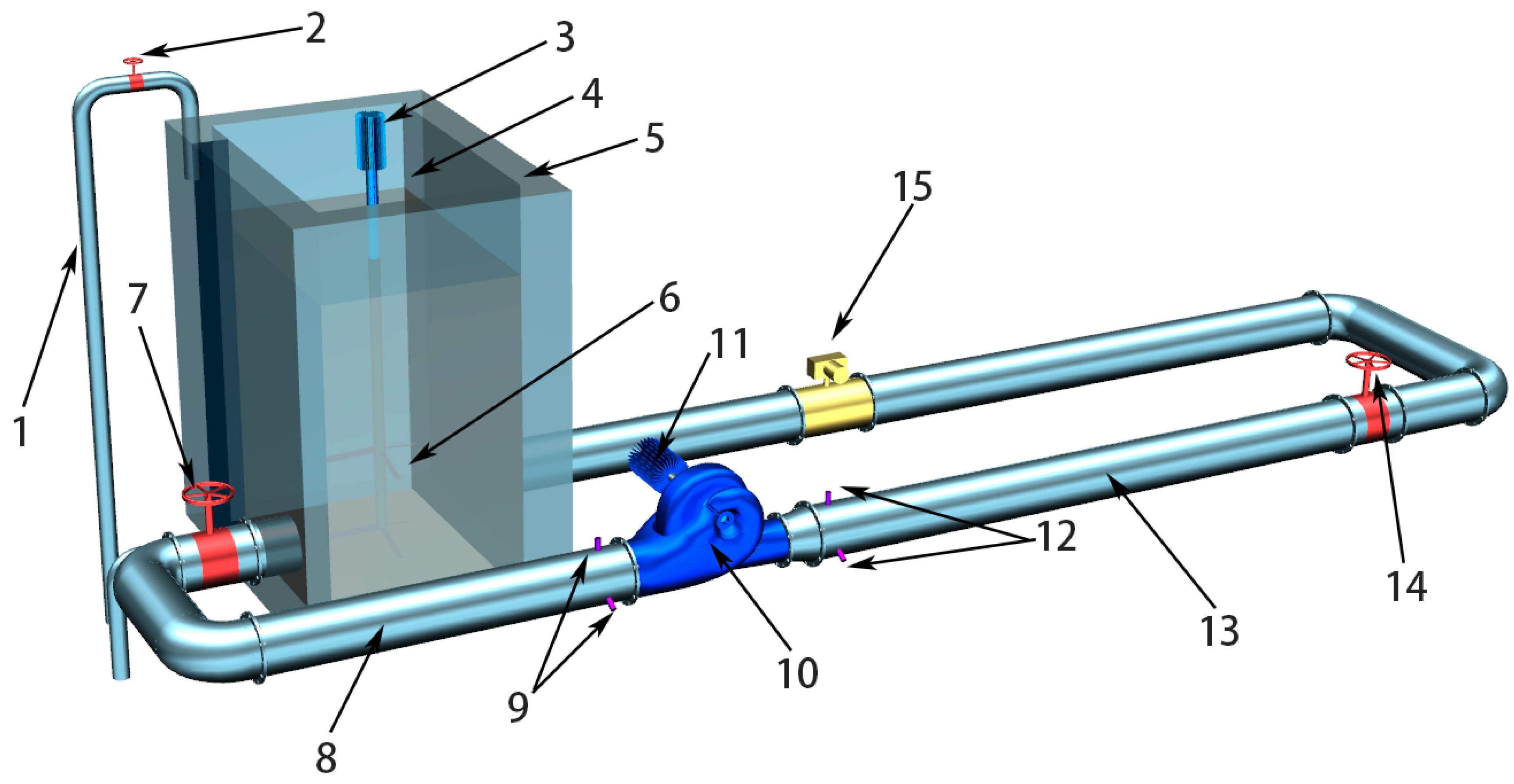
2.1.1. Test Rig

Figure 3 shows the experimental system, composed of three sections: (1) A water supply section with pipe for water supply, an adjusting valve, water tank and sand agitator with an electromotor; (2) a pump section with a pressure transducer, asynchronous motor and double-suction centrifugal pump and (3) an outlet section with a pressure transducer, adjusting valve and electromagnetic flowmeter. In the process of the experiment, sandy water was first pumped from the water tank by the test pump through the inlet pipe and then flow back to the tank after flowing through the whole experimental loop. The volume of the recycling water in the water tank was 3.785 m3. The valve fixed in the outflow pipe controlled the flow rate of the pump and was adjusted according to the record of the electromagnetic flowmeter to ensure that the pump operated at the designed flow rate. The stirrer continued working throughout the experiment to prevent sediment particles from settling and to ensure a constant sediment concentration in the water. The outer wall of the water tank is equipped with a water cooling jacket to keep the test temperature constant. The test pump, shown in Figure 4, is a prototype double-suction centrifugal pump extensively applied in the Yellow River irrigation district. The key parameters of the test pump are given in Table 1.

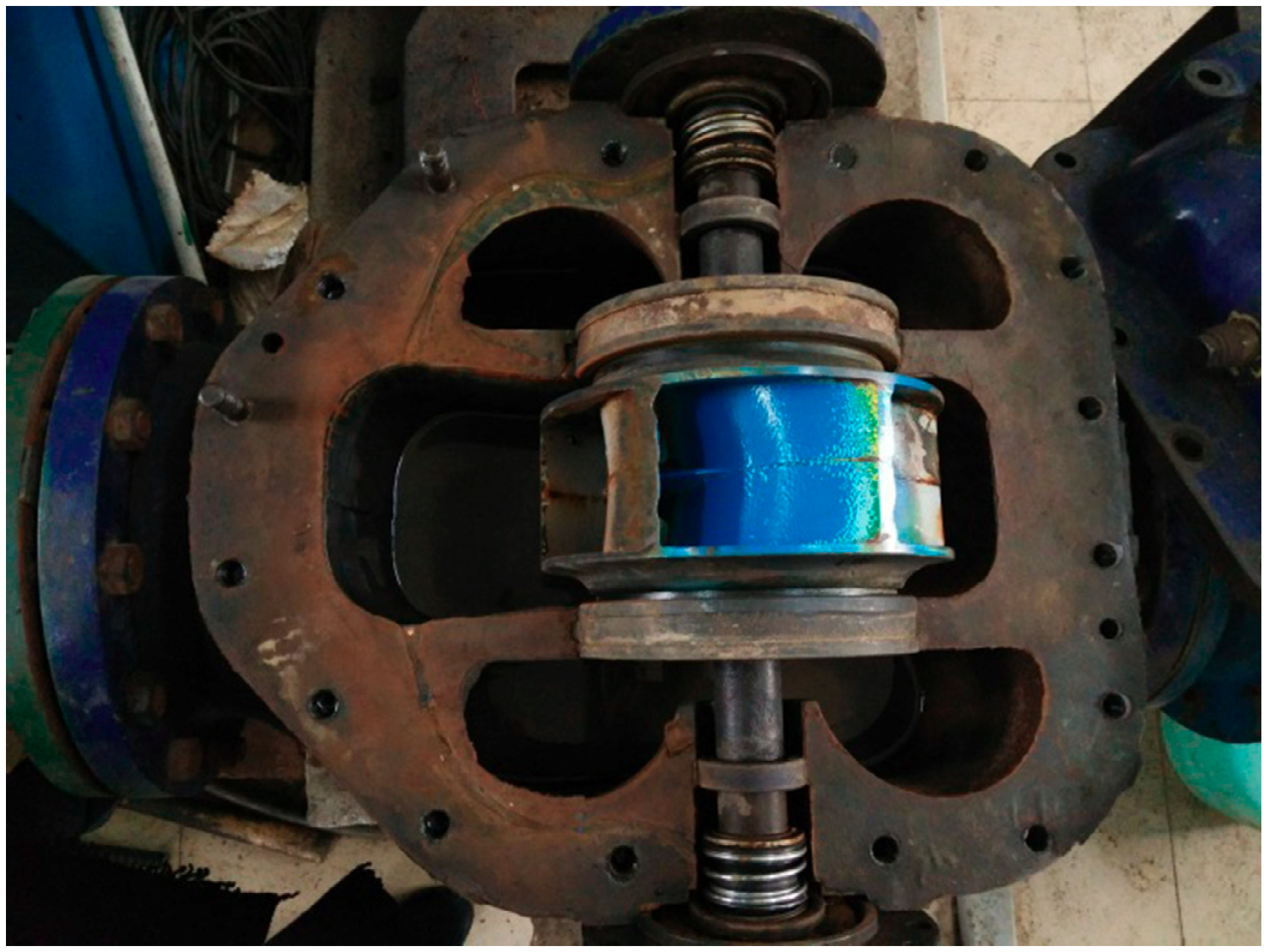
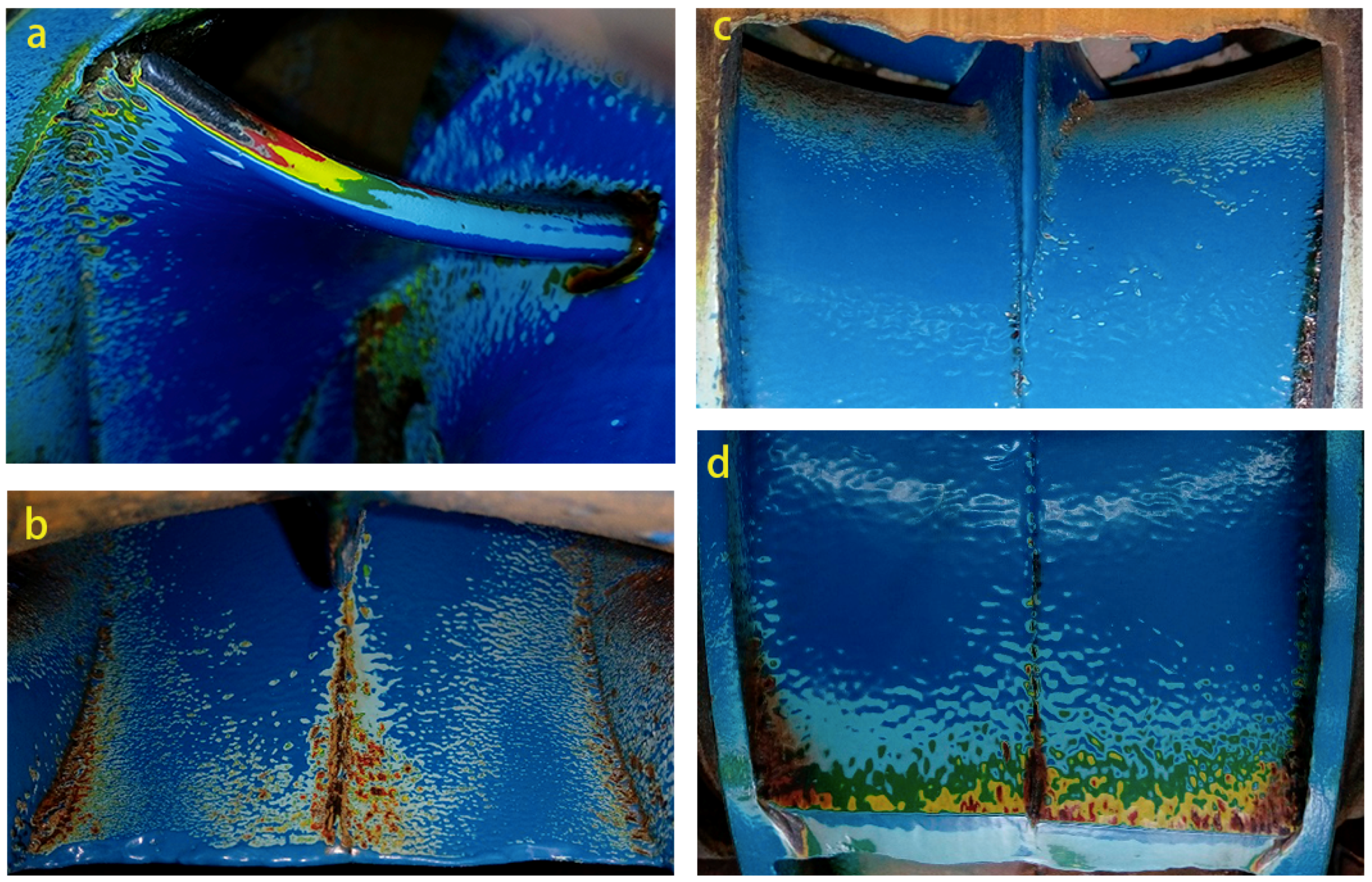
2.1.2. Painted Impeller

The tested pump impellers were made of cast iron. To quickly obtain the position and intensity of the silt erosion of the impeller, five different paint colors were sprayed on the impeller surface. Paint layers were employed by means of a spray gun with compressed air. Before spraying paint on the blade surface, iron rust was sand blasted and scoured away using high-pressure water to reinforce the adhesive property of paint to the blade surface. Two types of paint, polyurethane paint and epoxy paint, were investigated and epoxy paint was found to adhere better to the blade surface. A layer of gray antirust paint was first sprayed on the surface to enhance the adhesion of paint and cast iron. Red paint with thickness of 30 micrometers was then sprayed on the surface. Once this paint layer was applied, the impeller was put in an oven for an hour to promote the drying of paint. After another 2 h, when the paint had dried completely, the next layer of paint of a different color was applied following the same procedure as used previously. The silt-erosion intensity distribution of the impeller was obtained from the extent of paint erosion. The paint color from the outer- to the innermost layer was in order of dark blue, light blue, green, yellow and red based on an erosion intensity from weak to strong.

2.1.3. Sand Sampling

The sand used in the experiment was collected from the Ningxia Yanhuangding Pump Station (one of the Yellow River pumping stations) to ensure that the test environment was similar to practical conditions. Sediment particles sieved into different size ranges were dried and then weighed to compound sand-laden water of a certain concentration. In the experiment, a typical sediment size range of 0–0.08 mm at a 10 kg/m3 concentration was tested to obtain the silt erosion of the impeller.

2.1.4. Experimental Procedure

Pure water of 3.785 m3 was first injected to the water tank. Sand with a certain weight was then added to the water tank and mixed by a stirrer. The pump started working when the sand-laden water was uniformly distributed, and the outflow valve was adjusted to achieve the designed flow rate 485 m3/h. Every 4 h, the pump was stopped, and sediment-laden water was taken away. The pump was then dismantled to take photographs of the eroded blade surface. Following data collection, the pump was reassembled for the next cycle of the erosion test.

2.2. Numerical Simulation

2.2.1. Simulation Method

Internal flow in the double-suction centrifugal pump was calculated by applying three-dimensional incompressible Reynolds time-averaged Navier–Stokes equations. To close the equations, the Shear-Stress Transport (SST) k-omega turbulent model [25] was used. The equations for turbulence kinetic energy k and the specific dissipation rate ω are:
( ρ k ) t + ( ρ k u i ) x i = x j [ Γ k k x j ] + G k Y k ,
( ρ ω ) t + ( ρ ω u i ) x i = x j [ Γ ω ω x j ] + G ω Y ω + D ω ,
where G k represents the production of k ; G ω represents the generation of ω ; Γ k and Γ ω represent the coefficients of the effective diffusion for k and ω , respectively; Y k and Y ω stand for the divergence terms for k and ω , respectively; D ω denotes the orthogonal divergence term.
The interaction between sediment particles and water flow as well as the inter-particle collision were calculated using the Euler–Lagrange multiphase flow model. Silt motion was simulated using a Lagrangian reference system, which is defined as [26,27]:
d u p d t = F D ( u u p ) + g ( ρ p ρ ) ρ p + F
where u p and u represent the particle velocity and the water velocity, ρ is the water density, ρ p is the particle density, F D ( u u p ) is the drag force and F represents additional forces, which can be crucial under certain conditions. The first force of these, which is needed to accelerate water that surrounds the solid particle, is the virtual mass force. The equation of this force can be defined as:
F = 1 2 ρ ρ p d d t ( u u p ) .
The pressure-gradient force was considered as another additional force, which is written as:
F = ( ρ ρ p ) u p u .
The maximum concentration of silt studied in this paper was 10 kg/m3. The corresponding volume fraction is around 0.36%, which is less than 10%, thus the Discrete Phase Model (DPM) [28,29,30,31] was adopted to calculate the erosion rate on the impeller blade, which is determined as:
R e r o s i o n = p = 1 N p a r t i c l e m ˙ p C ( d p ) f ( α ) v b ( v ) A f a c e ,
where m ˙ p represents the mass flow rate of the particle stream, C ( d p ) denotes the function of particle diameter d p , f ( α ) represents the function of impact angle α , b ( v ) is the function of the particle velocity relative to the target wall v and A f a c e represents the area of the cell face at the wall. In addition, the accretion rate, calculated as the particle stream striking a wall surface, is mass-flux and defined as:
R a c c r e t i o n = p = 1 N p a r t i c l e m ˙ p A f a c e .
The governing equations in space were discretized by using the finite-volume method using ANSYS FLUENT 15.0 (ANSYS Inc., Canonsburg, PA, USA). The steady calculation of the flow field was performed. The SIMPLEC (Semi-Implicit Method for Pressure-Linked Equations-Consistent) scheme was employed to solve the pressure-velocity coupling, with the PRESTO (PREssure STaggering Option) scheme for the pressure and the QUICK (Quadratic Upstream Interpolation for Convective Kinematics) discrete format for the momentum. The turbulent kinetic energy was discretized using the second-order upwind difference scheme. The convergence criterion was 10−4.

2.2.2. Boundary and Calculation Conditions

The inlet was given the mass flow rate with a value of 134.54 kg/s, whereas the outlet was set to the pressure outlet with a value of 137.30 kPa. The eroded particles are spherical sediment particles and the density was 2740 kg/m3. Four different particle sizes (0.04, 0.12, 0.2375 and 0.4725 mm) were studied numerically at the same concentration of silt with a value of 10 kg/m3, and the silt concentration of 2.0, 3.5 and 6.5 kg/m3 was simulated for a given silt particle size of 0.2375 mm. A moving reference frame was used to simulate the rotating impeller domain at 1450 rpm.

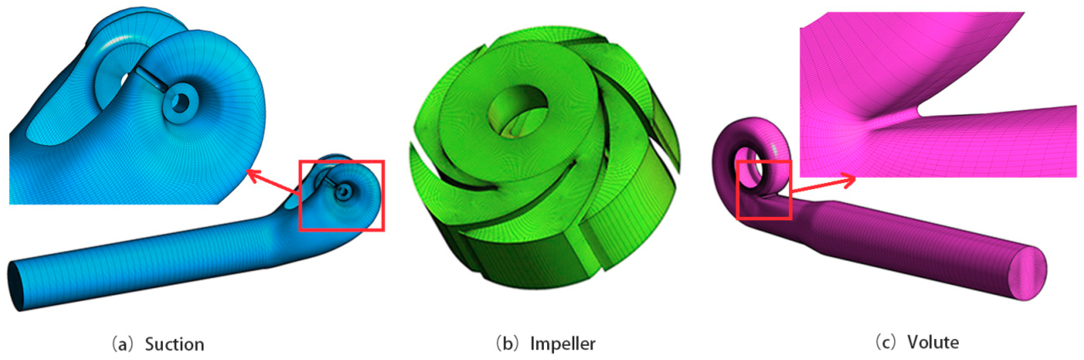
2.2.3. Three-Dimensional Model and Mesh of Pump

The computational pump was homologous with the laboratory pump. The geometric parameters of the physical model were scanned from the test pump and used to build the pump model. The computational domain was divided into three zones, namely, a suction chamber with a 1250 mm-long inlet pipe, an impeller and a volute with a 1250 mm-long outlet pipe. A structural hexahedra mesh, as shown in Figure 5, was used to discretize the computational domain. The O-type block was adopted for the impeller blades and circular pipes. Near-wall grids were densified for the capture of the detailed flowing behavior and the improvement of the solution accuracy. The mesh independence was checked [24] using five different mesh schemes; a mesh scheme of 3,403,876 elements was chosen for the calculation, for which the average wall y+ was less than 95, and was sufficient to meet the requirement of the wall 30–60 < wall y+ < 200–400 [32].

3. Results and Discussion

3.1. Experimental Validation

Figure 6 shows the experimental results of the silt erosion on the painted impeller after 48 h of operation for silt-laden water that contains 0–0.08 mm diameter silt at a 10 kg/m3 concentration. Figure 6a shows that the leading edge of blade close to the shroud suffers serious silt erosion, with the paint worn off completely; the outer margin of the suction side is also subjected to silt erosion, especially for the inlet of the suction side near the shroud. Figure 6b shows that the silt erosion on the blade suction side is spread from the inlet to the outlet, and the erosion near the middle of the blade and the blade outer edge is serious, where the red paint and blade surface emerged. Figure 6c shows that the inlet section of the pressure side is eroded and then the silt erosion becomes weak from the inlet section to the middle part of the pressure side. Figure 6d shows that the outlet section of the pressure side suffers relatively severe silt erosion; serious silt erosion appears on the outlet edge, with the paint worn off to a varying degree, and yellow and red paint and even the metallic surface are visible. The velocity of fluid flow has been found to have great effect on silt erosion in previous studies [4,6], as the particle impact speeds are approximately to the square of the fluid speed [6]. Figure 7 shows the relative velocity (in this paper, “relative velocity” refers to the velocity of water relative to impeller) around the blade surface. Figure 7a shows the relative velocity at the blade inlet, the outer margin of the blade (except for the outer margin of the outlet) and the middle of the blade outlet is high. The impact speed of the particles on these positions of blade surface is thus high, which can explain why the paint in the corresponding locations in Figure 6a,b suffers from relatively severe erosion. Figure 7b shows the relative velocity at the outlet section of the pressure side is relatively large, where the paint was also observed to be eroded in Figure 6d.
Figure 8 displays the numerical results of the erosion-rate distribution on the blade surface. The silt-particle diameter is 0.04 mm, which corresponds to the median size of the experimental particles, and the silt concentration is 10 kg/m3, which is equal to the experimental value. In Figure 8a, a high erosion rate results on the leading edge of blade close to the shroud, which indicates that serious silt erosion occurs. The suction side suffers a large area of silt erosion, and relative severe silt erosion appears at the inlet near the shroud, the middle part and the outer margin near the outlet section of suction surface, where the erosion rate is relatively high. Figure 8b displays that the eroded region is distributed mainly on the inlet section and outlet section of the pressure side, with a high erosion-rate region near the blade inlet and the middle region of the blade outlet. The area of silt erosion on the middle part of the pressure side is small.
Comparing Figure 8 with Figure 6, the location of the maximum erosion rate appears on the leading edge of the blade close to the shroud in Figure 8a, which is consistent with the location where the paint is completely worn away in Figure 6a. The location of a relative high erosion rate on suction side in Figure 8a appears at the inlet near the shroud, the middle part and the outer margin of the outlet section, which is close to the pattern of sediment erosion reflected by the extent to which the paint is worn away in Figure 6a,b. The erosion rate in Figure 8b is mainly distributed on the inlet and outlet of the pressure side, which is identical to the location of paint being worn off in Figure 6c,d. The erosion pattern as predicted by the numerical simulation is basically the same as that obtained from the erosion test, which indicates that the erosion prediction model that is used in this paper is reliable.

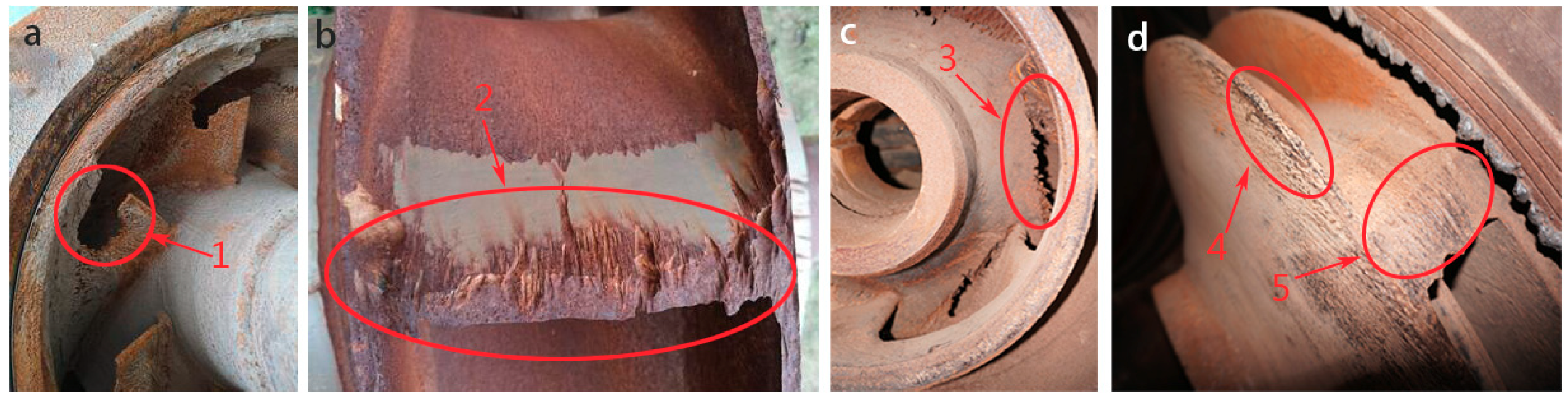
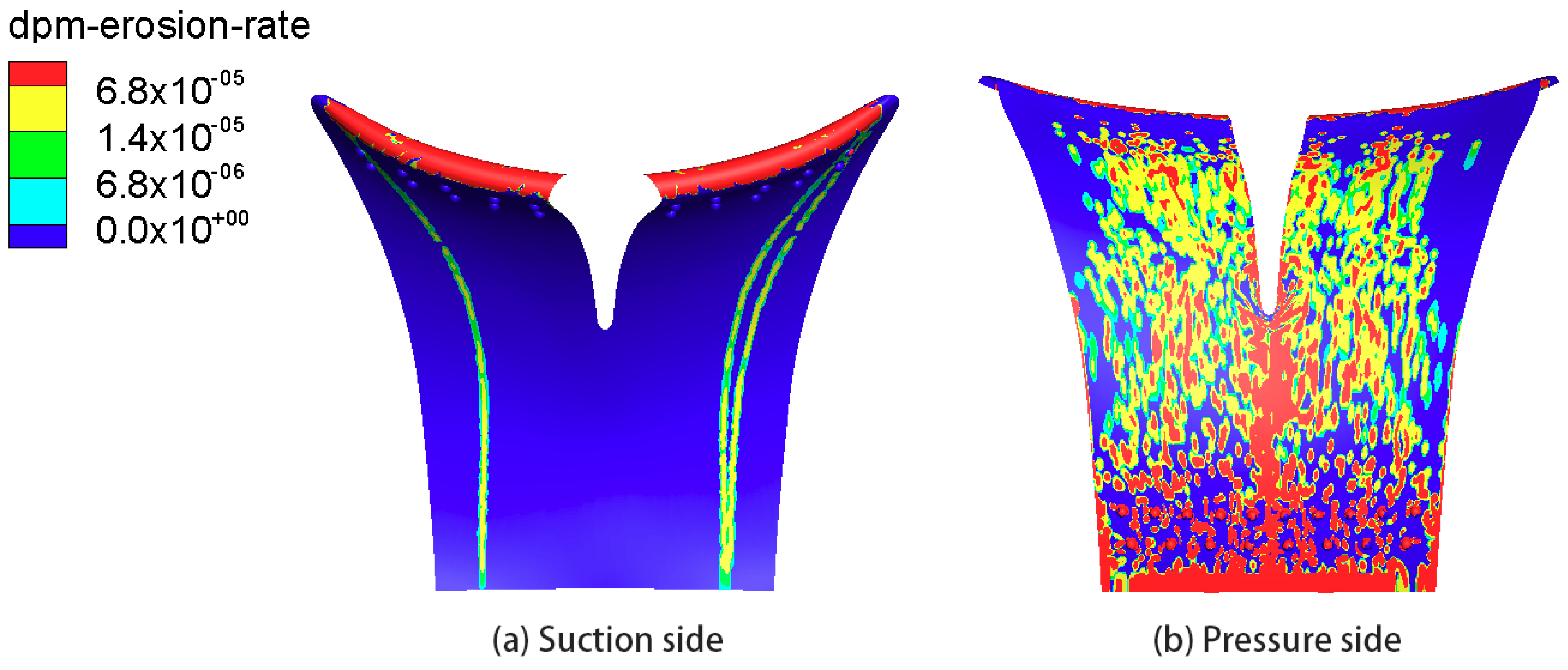
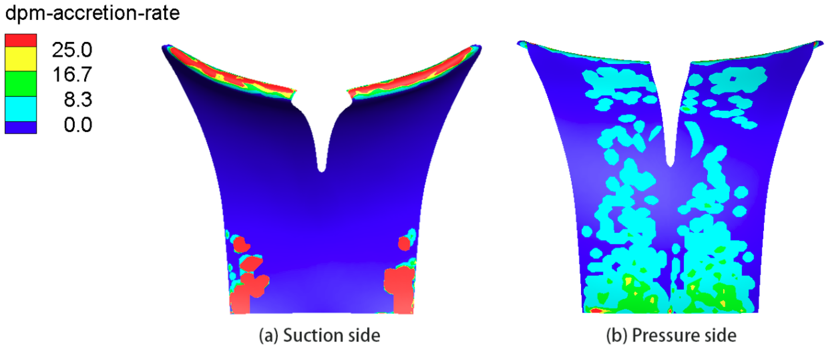
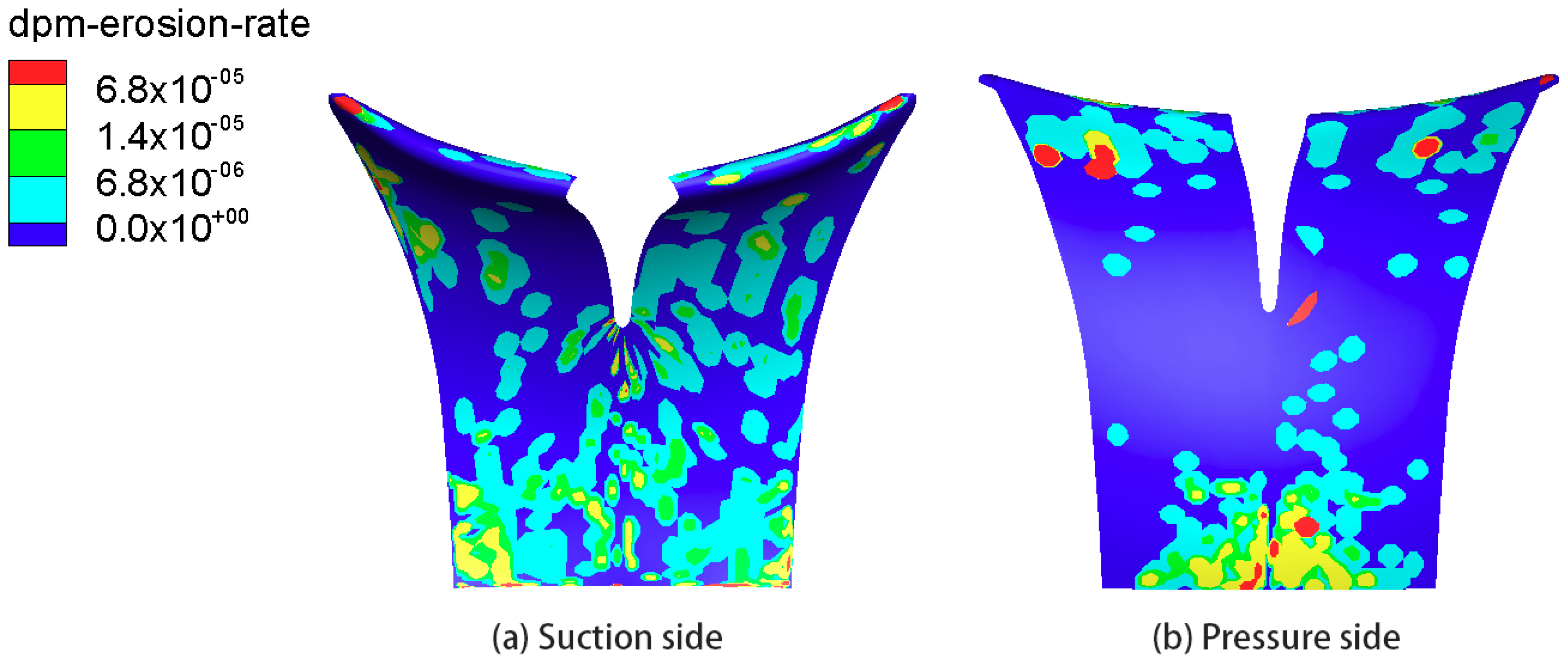
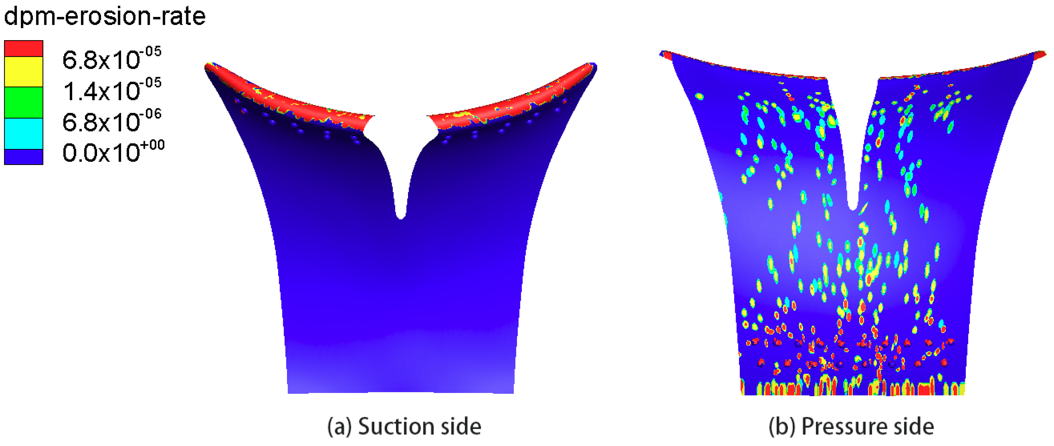
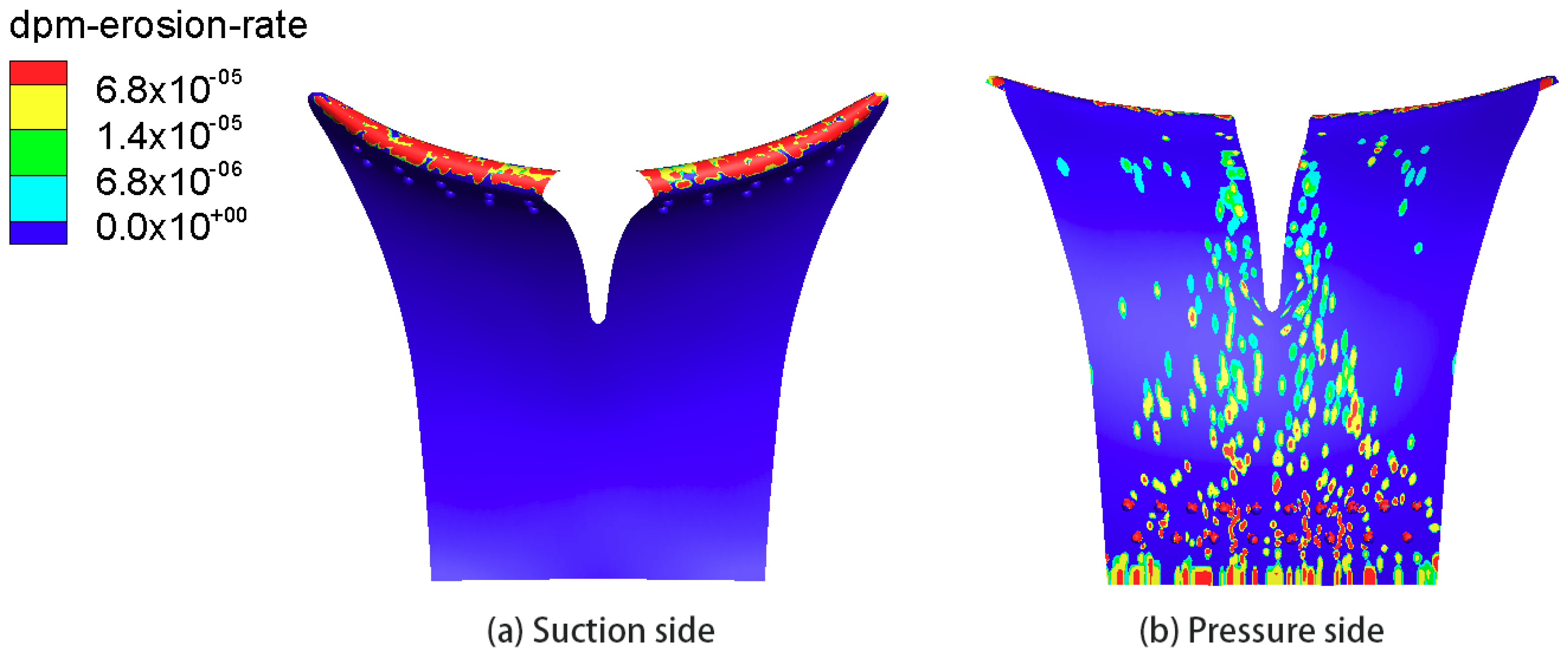
3.2. Erosion Characteristics of Prototype Blades

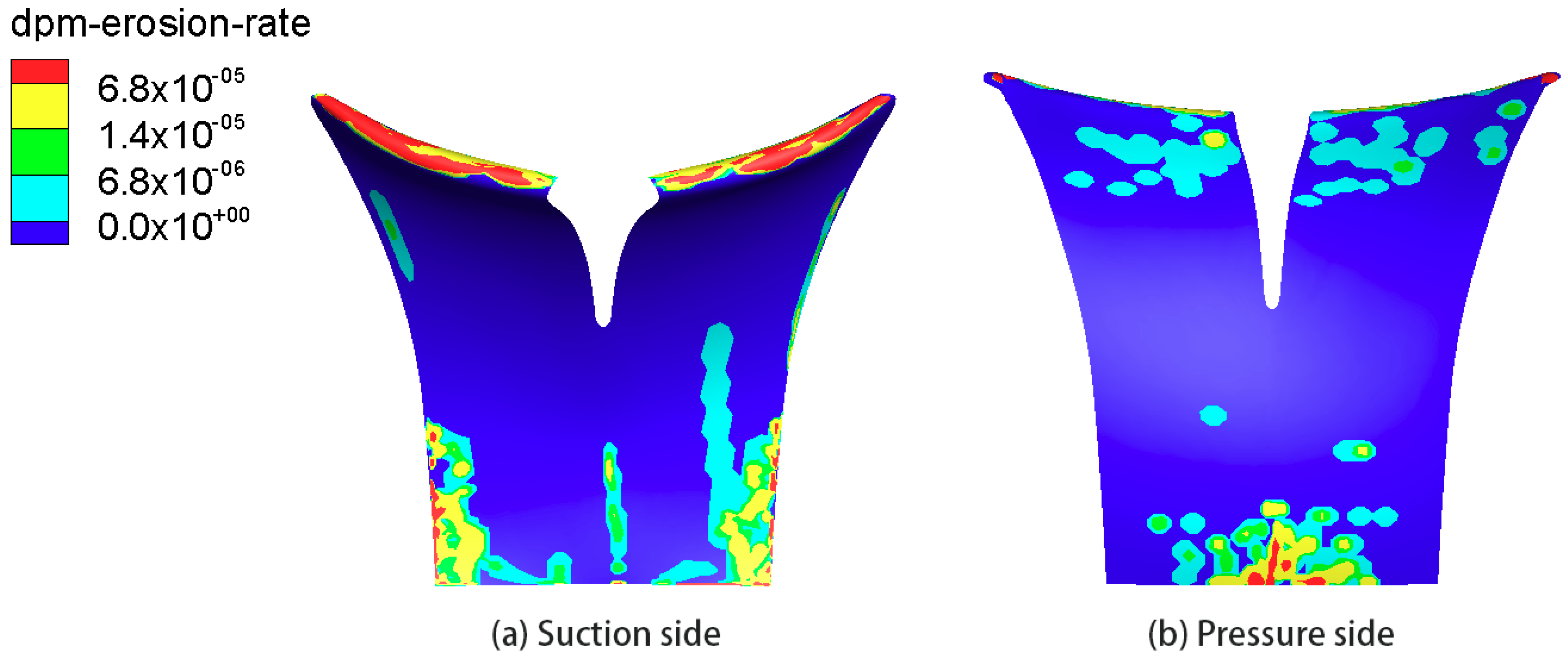
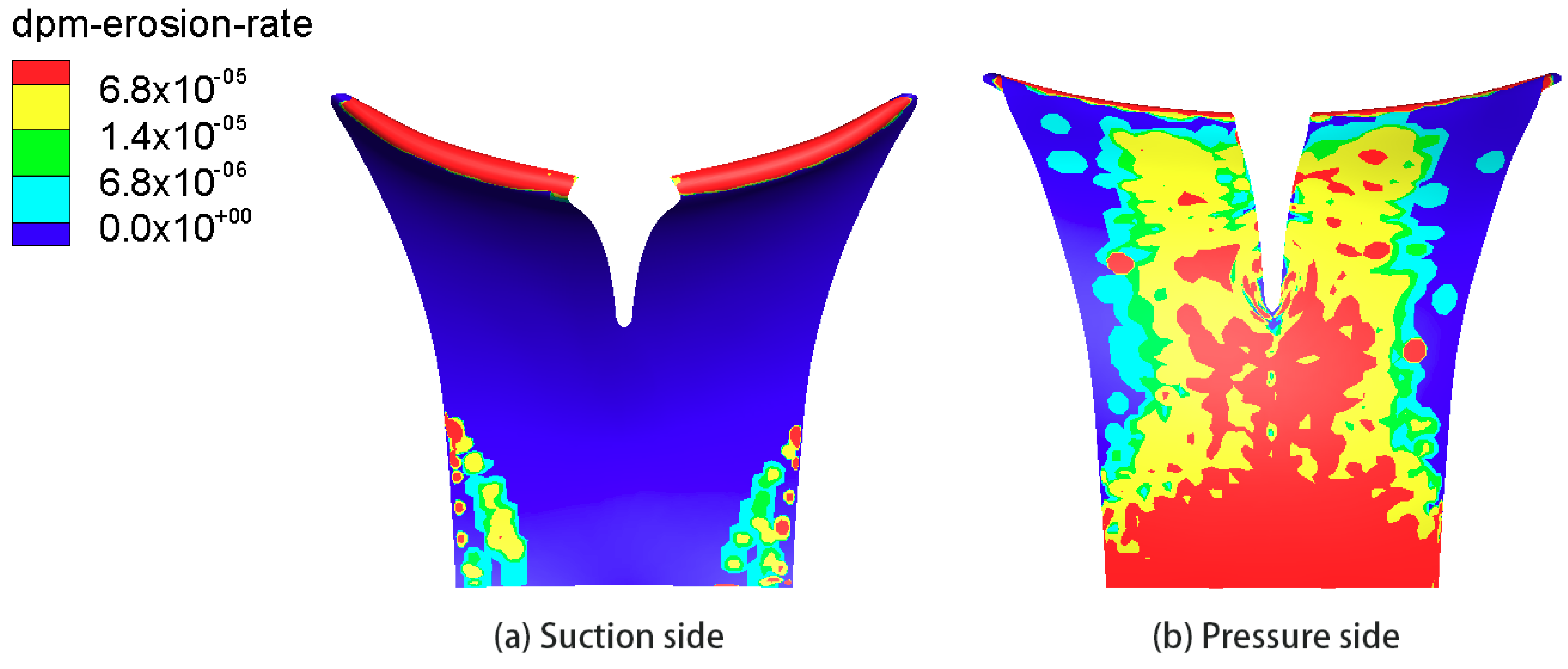
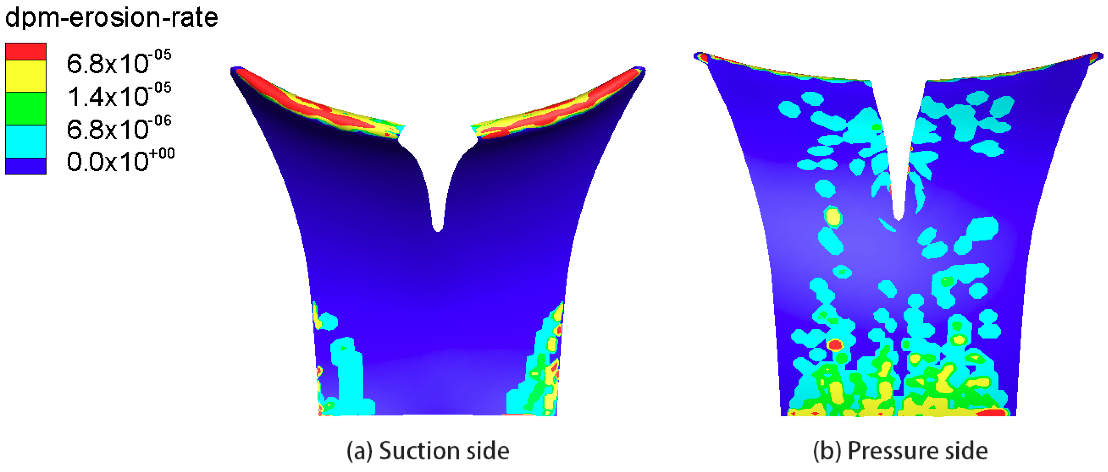
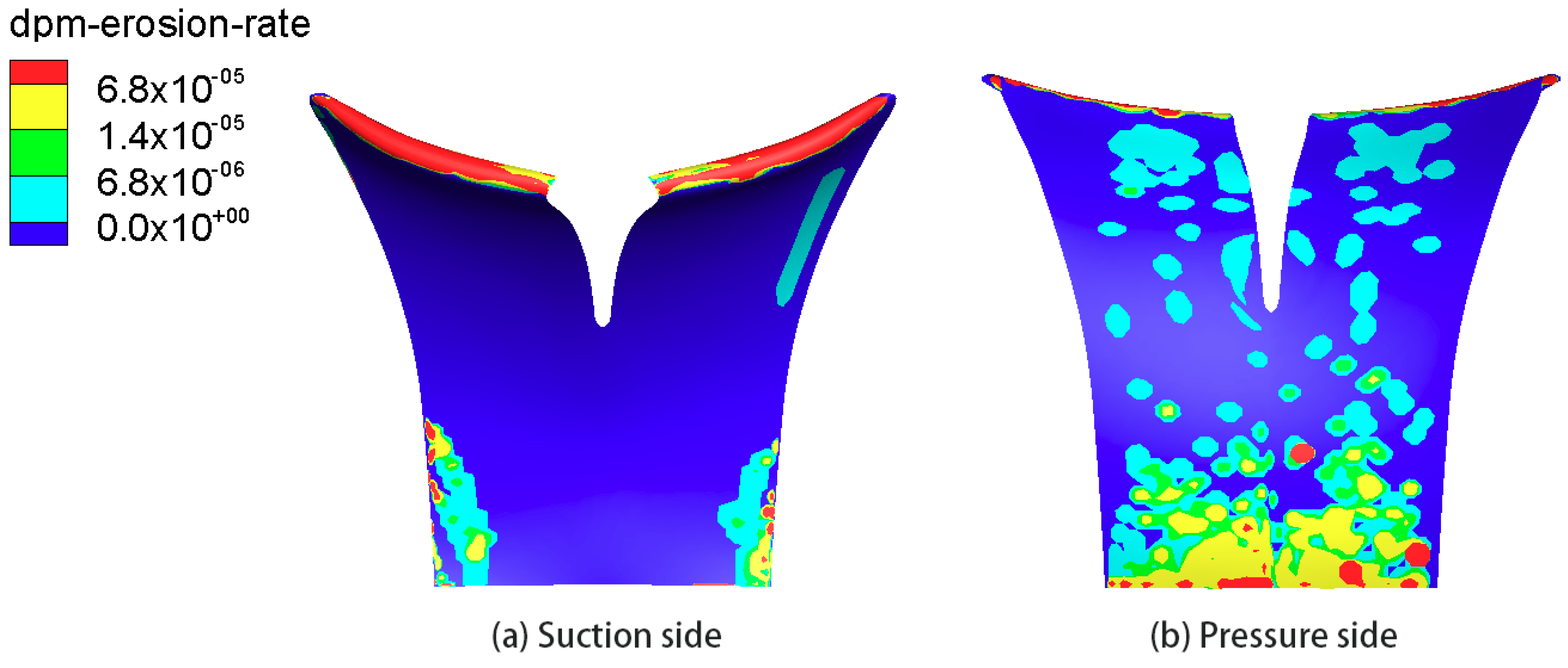
3.2.1. Effect of Silt Size

The effects of four different particle sizes (0.04, 0.12, 0.2375 and 0.4725 mm) on the silt erosion were simulated numerically. Figure 8, Figure 9, Figure 10 and Figure 11 show the erosion rates on the blade surface under these particle-size conditions, respectively. The numerical results show that the silt size plays a noticeable role in the silt-erosion characteristics of the blade.
The silt erosion on the leading edge of blade becomes serious as the silt size increases. Under the 0.04 mm condition, severe silt erosion appears mainly on the leading edge of blade close to the shroud, as shown in Figure 8a. With silt size increasing, the entire leading edge of blade is eroded heavily, as shown in Figure 9a, Figure 10a and Figure 11a.
For the suction side of the blade, the particle size mainly affects the distribution of eroded position. There is a noticeable change of the eroded position with different size particles: Small silt particles of 0.04 mm tend to abrade the entire surface of suction side, whereas large silt particles of 0.12, 0.2375 and 0.4725 mm are likely to abrade the outlet section of the suction surface.
For the pressure side of the blade, as the particle size increases, the silt erosion is reduced initially and then increases. Silt erosion on the pressure side for the 0.12 mm condition is lowest compared with that of the other silt size conditions, because the area of the silt erosion and the high erosion-rate region are both the smallest. The erosion distribution of the 0.04 and 0.12 mm conditions is similar on the inlet and outlet section. A comparison of silt erosion for the 0.12, 0.2375 and 0.4725 mm conditions demonstrates that the silt erosion increases with an increase in particle size. As shown in Figure 9b, Figure 10b and Figure 11b, the entire erosion area and the high erosion-rate region increase as the silt particle size increases.
Erosion results from the impact of silt particles against the blade surface. To explain the effect of silt size on the erosion characteristic, the trajectories of the 250 silt particles under 0.04 and 0.4725 mm conditions are tracked as shown in Figure 12, which is calculated through the integral of the force balance on the particle in ANSYS FLUENT 15.0. In this force equilibrium, the inertia of particle is equal to the forces acting on the particle. The silt size is related to the influence of inertia, and a larger particle size yields a stronger inertial effect [10]. Figure 12 shows the particle trajectories are biased towards the pressure surface, and the trend is more obvious as the particle size increases by comparing Figure 12a with Figure 12b. The numerical results of the particle trajectories are close to the experimental studies by Xu [33] and Liu [34].
Under the 0.04 mm condition, because of the small particle size, the inertial effect is weak, and the particle motion is dominated by the water turbulence. As shown in Figure 12a, the trajectories are distributed evenly inside the impeller, as small silt particles have similar flow properties to water [7,35]. Therefore, a certain number of sediment particles move near the pressure and suction sides of the blade, and collide with the pressure and suction surfaces of the blade to cause silt erosion in a relative large area of the blade surface.
Under the 0.2375 and 0.4725 mm conditions, because the particle size is large, the effect of particle inertia on its motion is strong. The particle trajectories of these sizes mainly move close to the pressure side. Consequently, the pressure sides of the blade under 0.2375 and 0.4725 mm conditions experience a more serious silt erosion, and the latter is eroded more severely than the former.
For the 0.12 mm condition, the effect of inertia and water flow on the particles is equivalent. Particle trajectories of this size are further from the pressure side than those of a smaller size (0.04 mm) with a better following property, and than those of a larger size (0.2375 and 0.4725 mm), which experience a stronger inertial effect. Therefore, for the 0.12 mm condition, the number of particles that erodes the pressure side of the blade is the smallest, and results in the lightest silt erosion on the pressure side. As the silt particles larger than 0.04 mm move away from the suction side, under the 0.12, 0.2375, and 0.4725 mm conditions, silt erosion of the suction side is concentrated at the outlet section.

3.2.2. Effect of Silt Concentration

To study the impact of the silt concentration on the silt-erosion characteristics, a sediment size of 0.2375 mm (the median size of 0.16–0.315 mm, and the content of sediment particles in this range is high) was chosen, and three typical silt concentrations of 2.0, 3.5 and 6.5 kg/m3 were studied because the concentration of sediment in silt-laden water pumped from the Yellow River is generally less than 10 kg/m3 during irrigation. Figure 13, Figure 14 and Figure 15 show the erosion rates on the blade surface under these silt-concentration conditions, respectively. For different silt concentrations, the silt-erosion position of the blade surface is basically the same, but the erosion strength increases with increasing silt concentration. This occurs because the volume fraction of solid particles is very small, which has little effect on the flow field. Therefore, the particle motion is basically consistent for a given silt-size, which leads to particles colliding with the surface of the blade in basically the same position. However, as the silt concentration increases, the number of colliding particles increases, which results in more severe silt erosion.

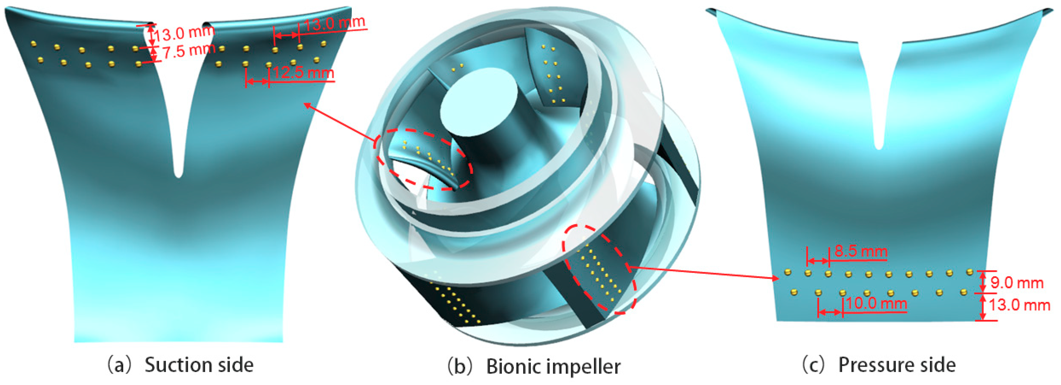
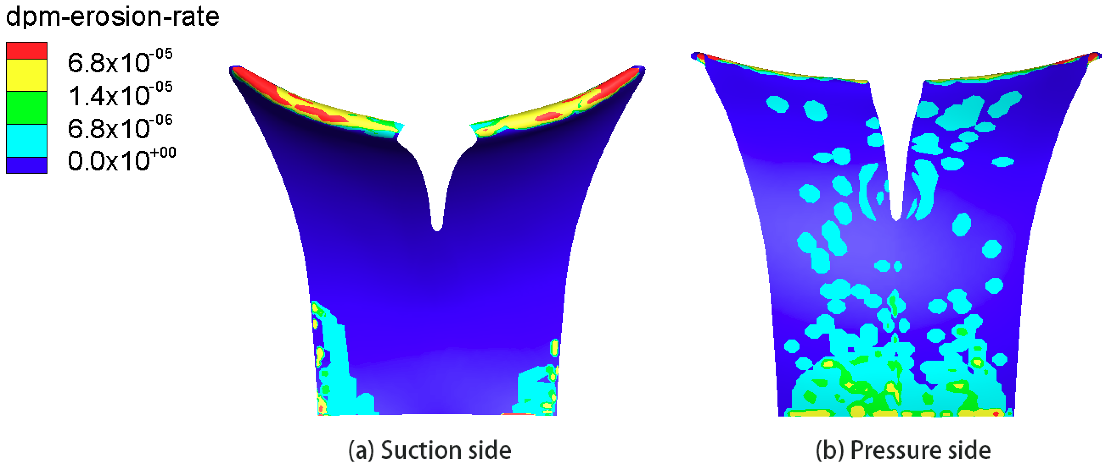
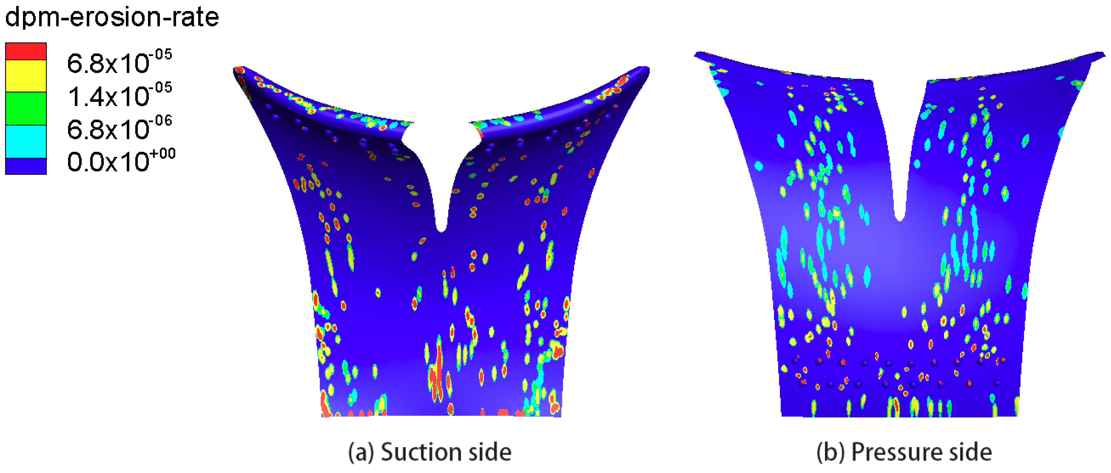
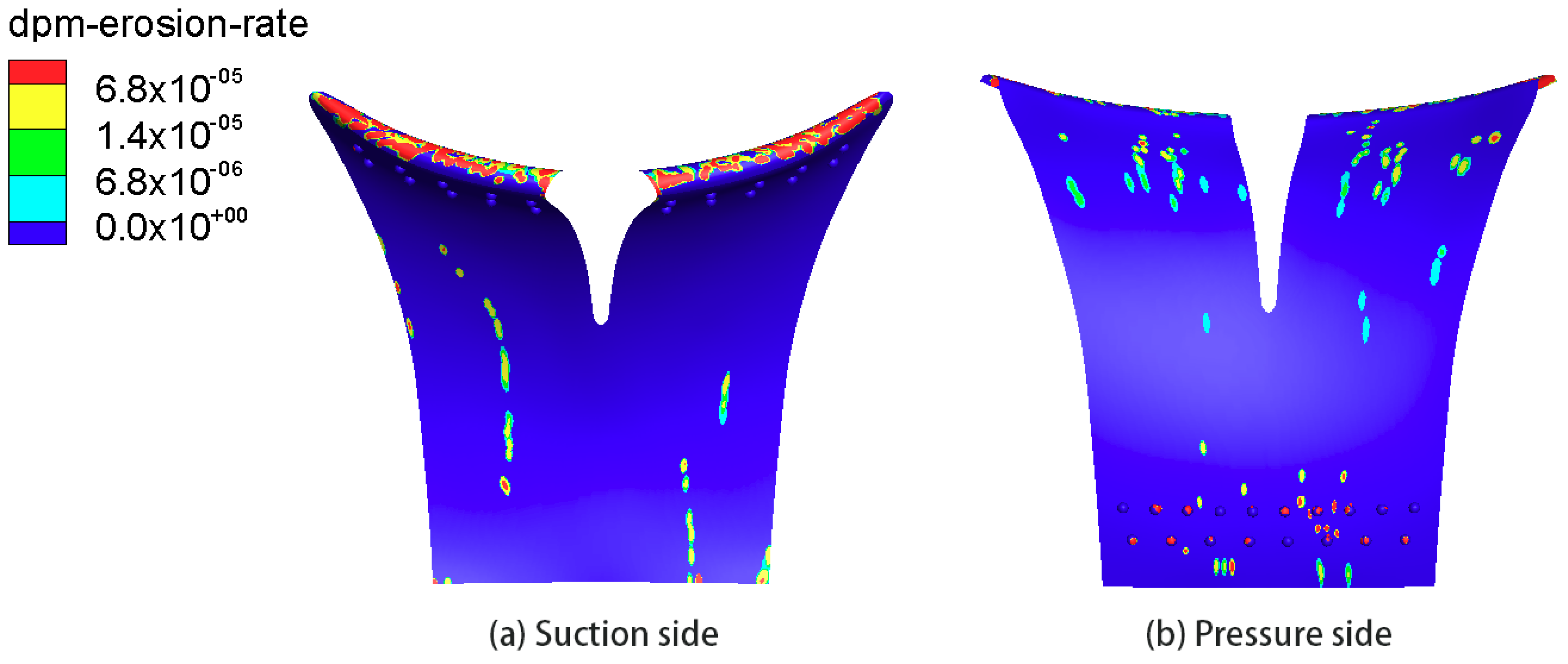
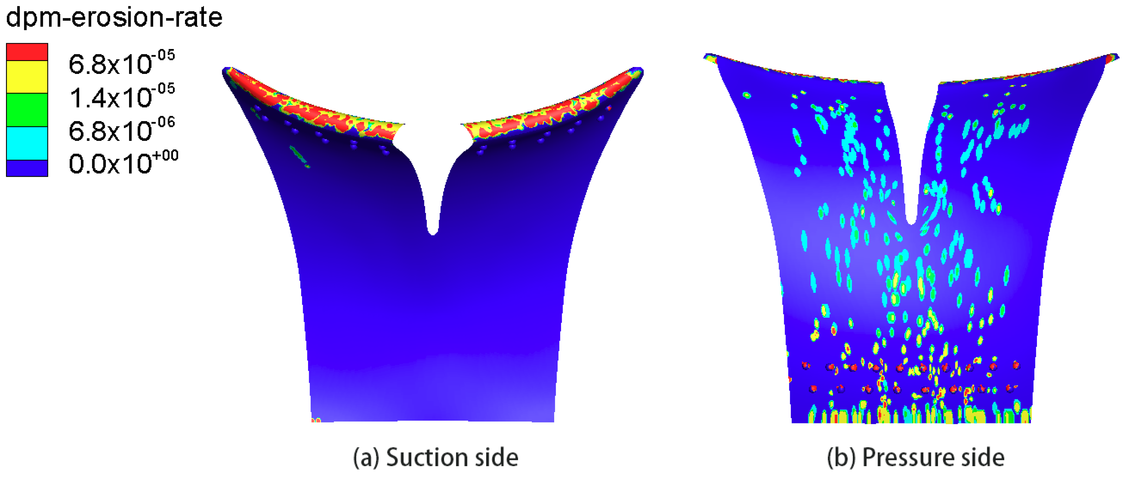
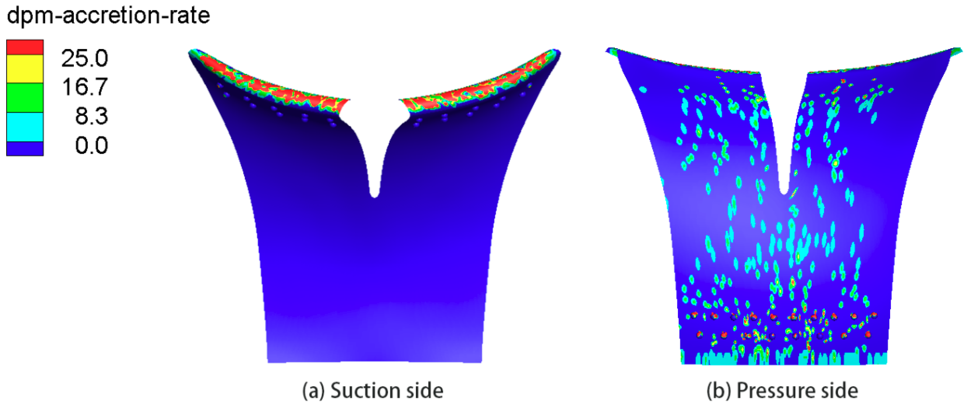
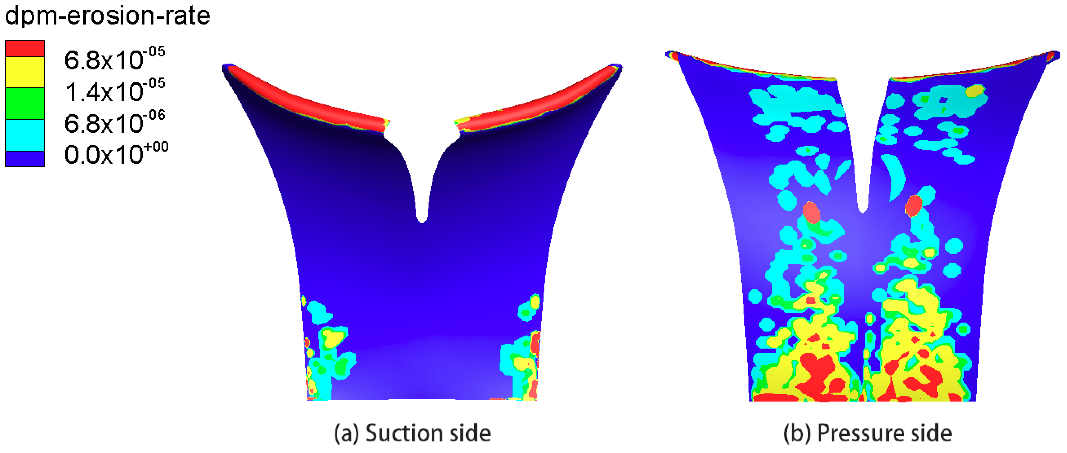
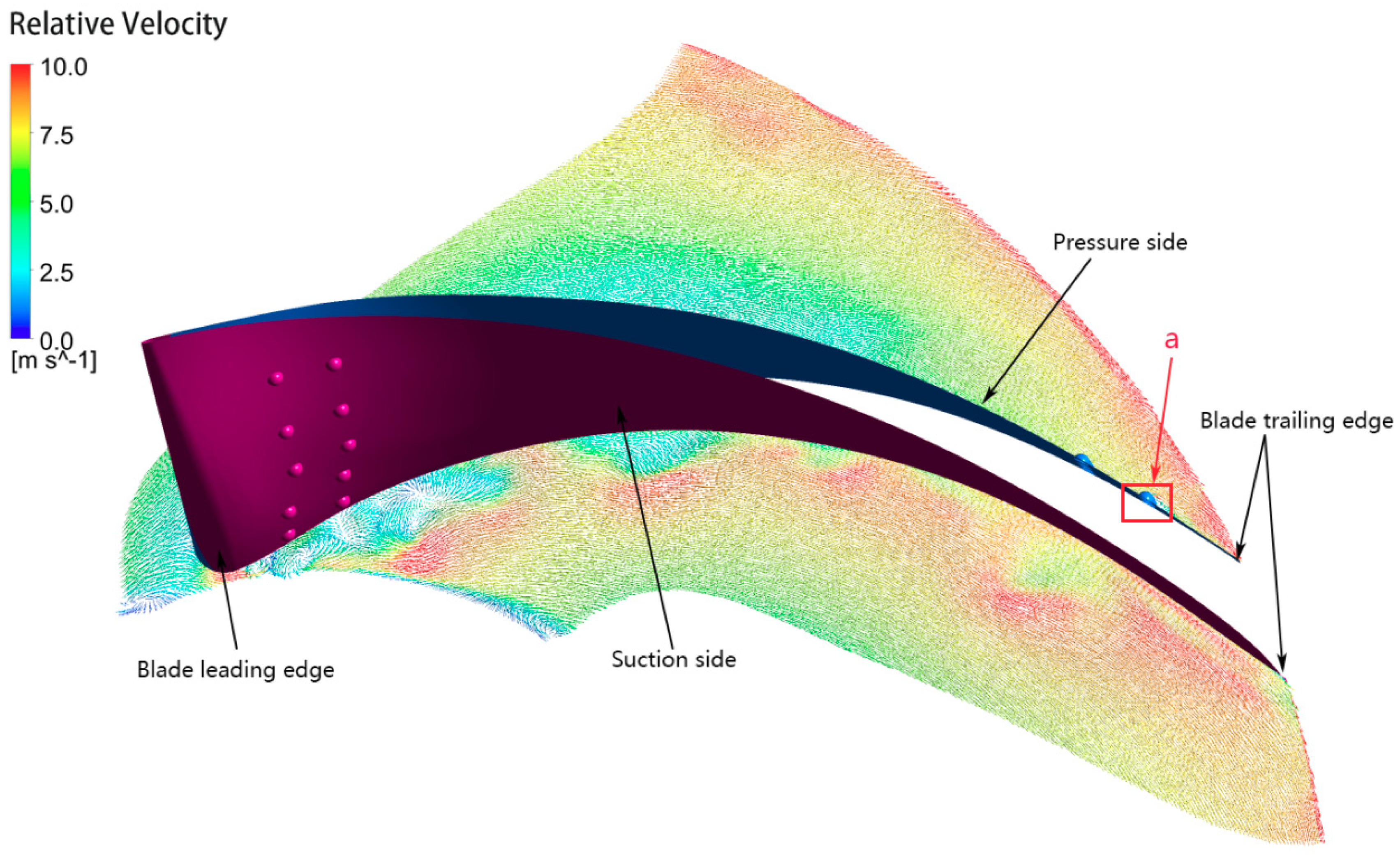
3.3. Erosion Characteristics of Bionic Blades

Our previous research [24] found that silt erosion can be alleviated by placing two rows of hemispherical bionic convex domes at the suction-side inlet and the pressure-side outlet. However, in that study, only silt erosion under a 0.02 mm condition was studied, and the results of Section 3.2 demonstrate that the particle size and silt concentration have a noticeable impact on the silt-erosion pattern of the blade surface. Therefore, the anti-erosion properties of the impeller with hemispherical convex domes with a radius of 1.5 mm under other particle-size and silt-concentration conditions were studied.
Figure 16, Figure 17, Figure 18 and Figure 19 show the erosion rate on the blades with bionic convex domes under 0.04, 0.12, 0.2735 and 0.4725 mm conditions, respectively.
For the 0.04 mm condition, the high erosion-rate region on the leading edge of blade with bionic convex domes becomes dispersed compared with that of the prototype pump (Figure 8), which helps to alleviate the locally intensive silt erosion. The area of silt erosion on both sides of the blade is reduced and the erosion region becomes smaller and scattered, without a large area of concentrated erosion on the blade inlet and outlet of the pressure side, but the erosion rate on the suction surface is larger.
For the 0.12 mm condition, the silt erosion on the blade with bionic convex domes is suppressed compared with that in Figure 9. The silt erosion on the leading edge of blade becomes dispersed; the erosion rate and the area of the silt erosion decreased on both sides of the blade.
For the 0.2375 mm condition, silt erosion on the blade surface with bionic convex domes is improved significantly compared to that of Figure 10: The erosion region on the leading edge of blade becomes dispersed, the silt erosion on the outlet section of the suction side disappears, the large area of the high erosion-rate region on the pressure surface is decreased significantly and the area of the silt erosion is decreased.
For the 0.4725 mm condition, the silt erosion on the blade with the bionic convex domes is less serious than that of Figure 11. The silt erosion on the leading edge of blade is also scattered; the erosion rate on the suction side is lower and the silt-erosion position appears closer to the middle of the suction side, rather than the outer edge of the blade outlet section that is prone to concentrated erosion. The area of the erosion on the pressure surface is reduced and the high erosion-rate region becomes dispersed, especially for that around the bionic convex domes on the outlet section of the pressure side.
Figure 16, Figure 17, Figure 18 and Figure 19 show that the bionic convex domes are eroded, especially under large silt conditions; however, the silt erosion on the blade surface is improved significantly and the blade itself is protected. A replacement of the bionic convex domes is more convenient and economical than impeller maintenance, which can shorten the downtime and enhance the economic benefits of a pumping station.
Figure 20, Figure 21 and Figure 22 show the erosion rate on the blades with bionic convex domes for silt concentrations of 2.0, 3.5 and 6.5 kg/m3, respectively. For the different silt concentrations, silt erosion on the blades with bionic convex domes is reduced in terms of the erosion area and erosion strength, compared with that on the prototype blades.
From the above comparisons, the bionic convex domes can improve the silt erosion of the blade surface for most of the investigated silt-laden water conditions by reducing the erosion rate and the area.

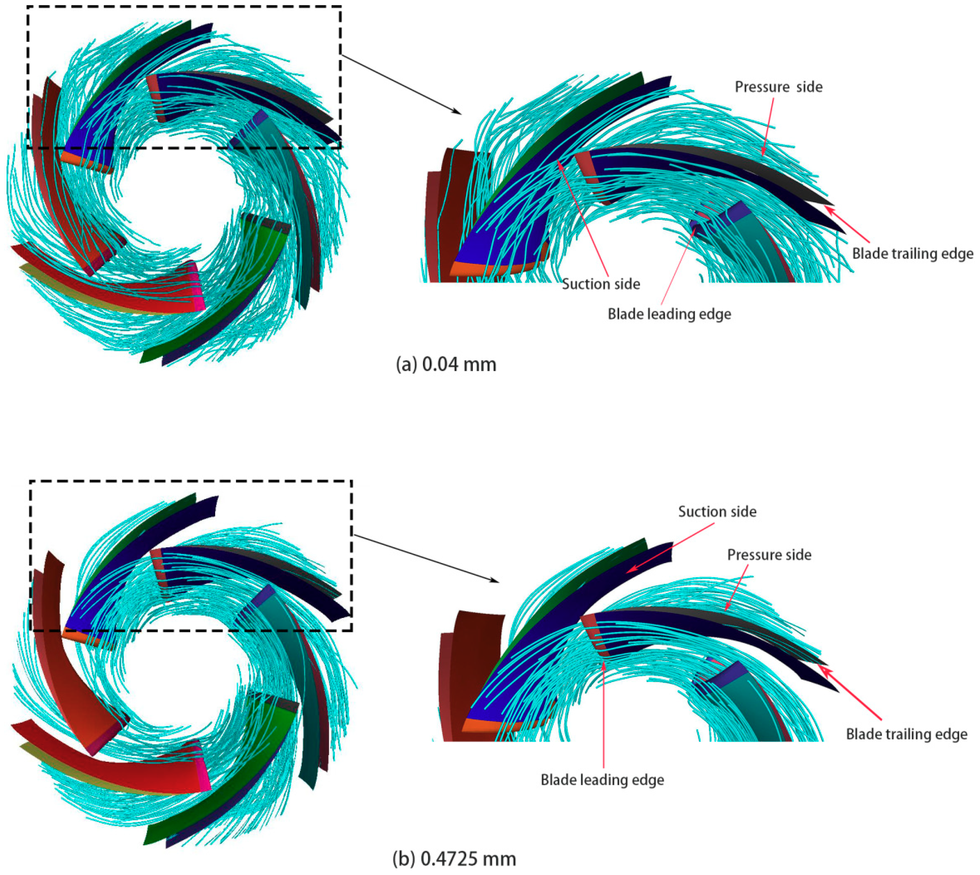
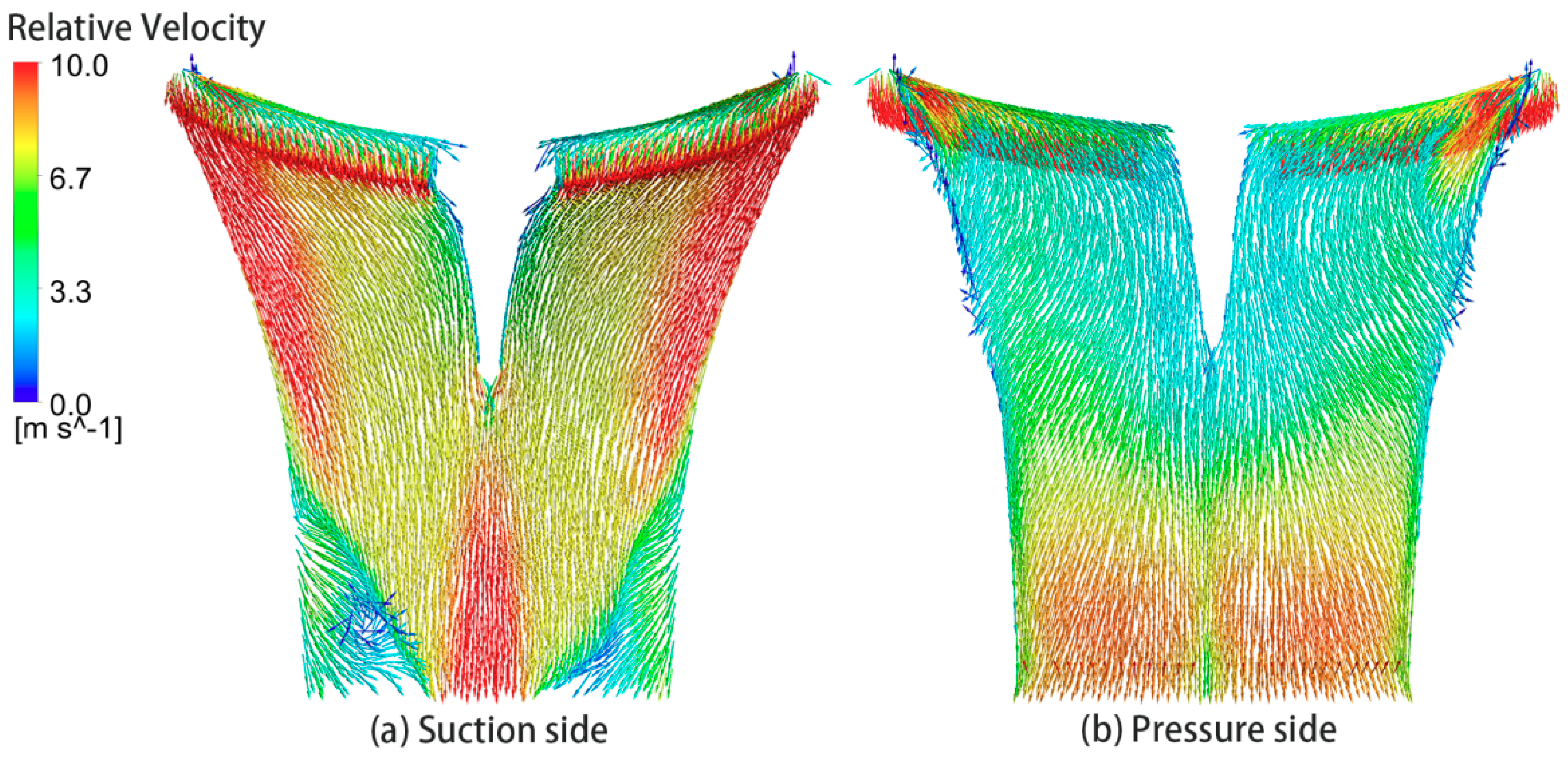
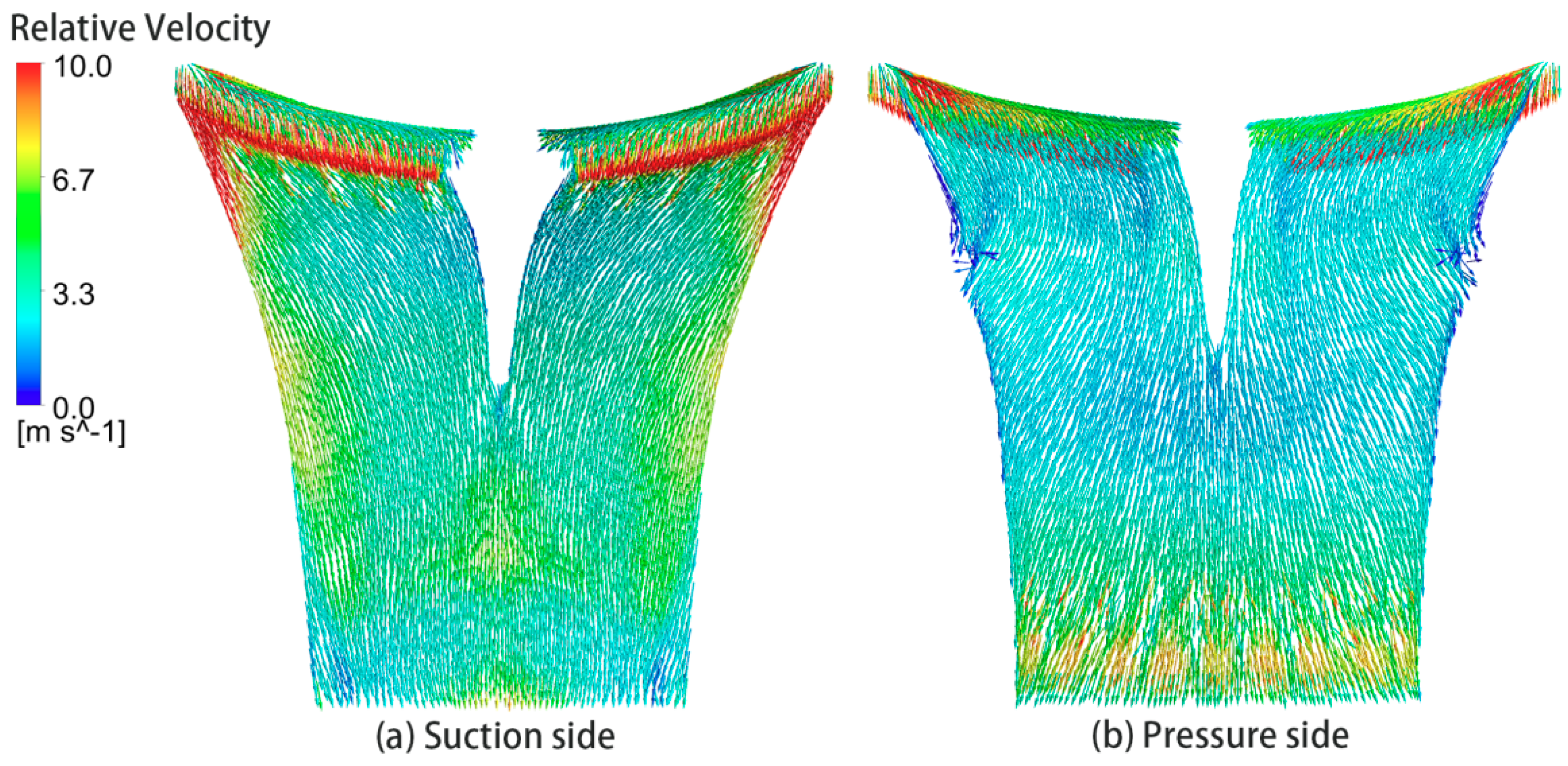
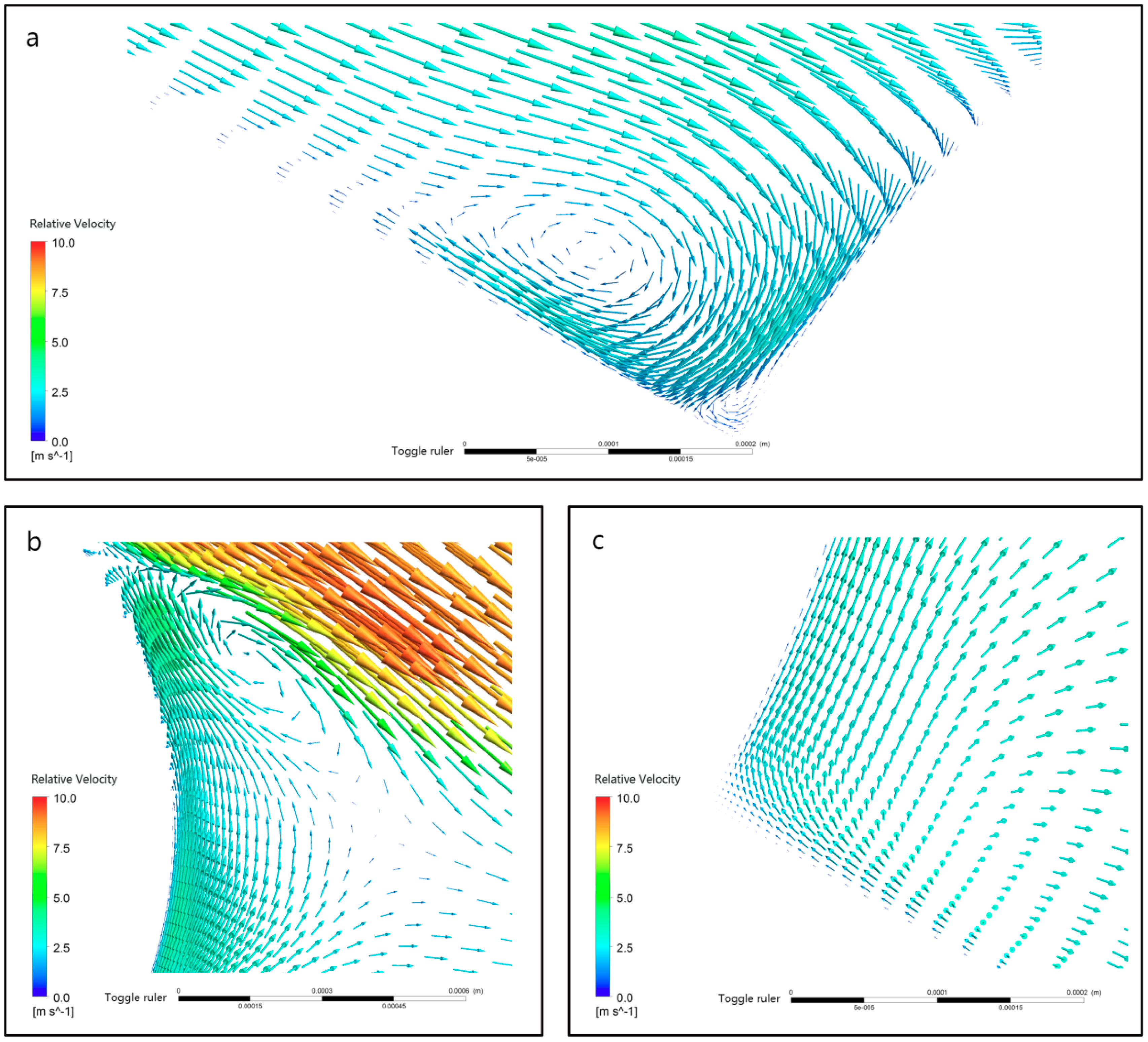
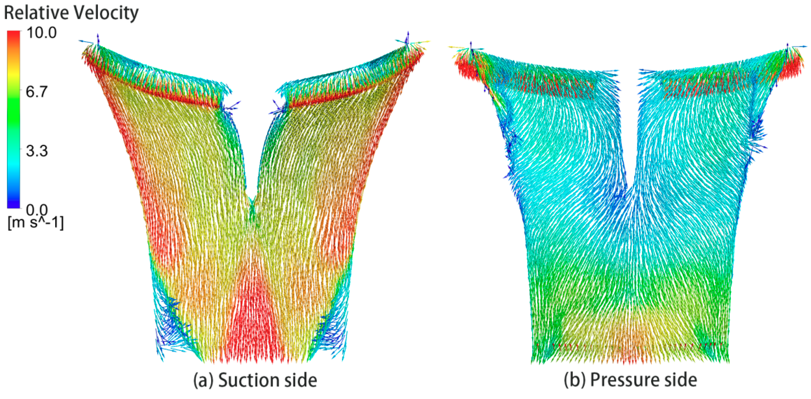
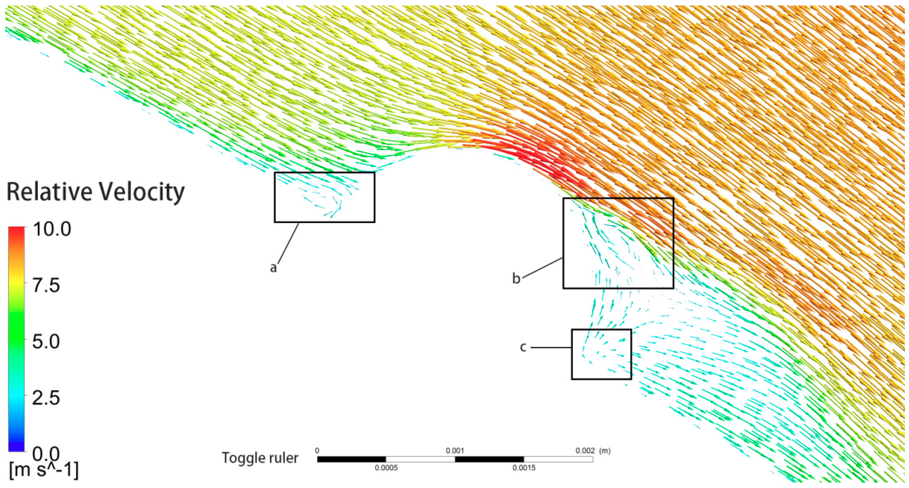
3.4. Analysis of Anti-Erosion Mechanism

The erosion rate defined by Equation (6) indicates that the surface erosion rate is determined by the relative particle speed and the number of particles that hit the surface for a given silt size. The motion of silt particles is determined largely by the water flow. To illustrate the influence of bionic convex domes on the silt erosion, the relative velocity of water around the blade surface and the accretion rate (which represents the mass flow rate of particles that strike the wall, defined as Equation (7)) for a sediment size of 0.2375 mm and a sediment concentration of 10 kg/m3 were selected as shown in Figure 23 and Figure 24 and Figure 25 and Figure 26, respectively. The bionic convex domes can affect the water flow around the entire blade surface. A comparison of Figure 23 and Figure 24 shows that the magnitude of the relative velocity of water around the blade surface with bionic convex domes is lower than that around the proto blade surface and the relative velocity distribution of water gets even more uniform, with no vortexes appearing on the outer margin near the exit section of the suction surface. Due to the lower relative velocity of water, the momentum that the particles obtained from the carrier fluid is lower, and the impacting speed of particles against the wall would be much lower. The change in flow field also influences the number of particles that hit the wall. Figure 26 shows that the accretion rate on the blade surface with bionic convex domes is decreased significantly, especially on the outer margin near the outlet section of the suction surface, compared with that of the prototype blade, as shown in Figure 25. Thus, the number of particles that hit the wall is also reduced, which results in a weaker silt erosion on the blade surface. The accretion rate on the bionic convex dome of the pressure side is high, and hence the bionic convex dome is seriously eroded.
To understand why convex domes decrease silt erosion, a large eddy simulation was adopted to capture the flow details around the bionic convex domes. Water flow in a single impeller passage was simulated and a periodic boundary condition was set. The total mesh number was ~16 million and the y+ was less than 1. A steady CFD simulation was performed and the steady result was used as the initial flow field for the unsteady calculation. The time step of the unsteady calculation was ~5.75 μs, which corresponds to 0.05° of a rotor passing angle. The convergence criterion was 10−6. The scaled residuals of velocity in the xyz directions decrease to 10−6, but the continuity residual remains at 10−4 during the iterations. We compared the net flux of mass flow rate at the inlet and outlet with the total mass flow rate at the inlet over two periods, and the ratio of the two is less than 0.001%, which indicates that the solution has converged. The calculation time was 20 rotation cycles and the last cycle data was used for the analysis.
Large eddy simulation results show that vortexes appear around all the convex domes. Figure 27a displays the location of convex dome shown in Figure 28. Figure 28 shows that the boundary-layer separation occurs around the convex dome. Swirls appear near the upstream and downstream faces of the convex dome. The relative velocity close to the top of the convex dome is large, thus the corresponding position is prone to serious silt erosion. Figure 29 shows a detailed view of the boundary layer separation around a bionic convex dome. It can be observed that the gradient of velocity parallel to the wall direction along the normal direction of the wall is less than zero. The direction of the flow velocity near the wall is opposite or perpendicular to the direction of the main flow velocity, which helps to reduce the impact velocity of sediment particles. Thus, swirls can form a vortex cushion effect and reduce the particle impact velocity when they pass through the vortex structure. Furthermore, swirls imply a high adverse pressure gradient around convex domes, which can change the particle motion according to the particle force Equation (3), make the particles deviate from the blade surface, and some particles may leave the blade surface without hitting the surface, which is reflected in Figure 25 and Figure 26.

4. Conclusions

The effects of four different particle sizes (0.04, 0.12, 0.2375 and 0.4725 mm) and three different silt concentrations (2.0, 3.5 and 6.5 kg/m3) on the silt-erosion characteristics of the blades in a double-suction centrifugal pump were studied and the anti-erosion performance of a blade with bionic convex domes under these operating conditions was simulated. A comparison of the numerical results with the experimental results of the silt erosion of a painted impeller shows good agreement. A large eddy simulation was conducted to reveal the anti-erosion mechanism of the bionic convex domes. The results are as follows:
  • The silt size affects the erosion position and erosion strength, whereas the silt concentration affects mainly the erosion strength, within the studied range. With silt size increasing, the silt erosion rate on the leading edge of blade increases, whereas the silt erosion rate on the pressure side of the blade decreases initially and then increases, and the silt eroded position on the suction side is different for a small and a large silt size. As silt concentration increases, the erosion position of the blade surface is basically the same, but the silt erosion rate increases.
  • The bionic convex dome is an effective method to reduce the silt erosion of the blade by changing the erosion pattern. The erosion rate on the suction side of the 0.04 mm silt size condition increased, but silt erosion on the blade with bionic convex domes under other conditions improved significantly by decreasing the erosion rate and the area.
  • Silt erosion was reduced when the bionic convex domes change the relative velocity of water around the blade surface and decrease the mass flow rate of silt particles that hit the blade by inducing swirling flows.

Author Contributions

Conceptualization, J.D. and Z.Q.; Data curation, J.D. and Z.Q.; Formal analysis, J.D. and Z.Q.; Funding acquisition, Z.Q.; Investigation, J.D. and Z.Q.; Methodology, J.D. and Z.Q.; Project administration, Z.Q.; Resources, Z.Q.; Software, J.D., Z.Q. and Z.G.; Supervision, Z.Q.; Validation, J.D., Z.Q. and Z.G.; Visualization, J.D. and Z.Q.; Writing—original draft, J.D.; Writing—review & editing, J.D., Z.Q., B.S.T. and B.T.

Funding

This research was funded by the Chinese National Foundation of Nature Science (grant number 51779186) and Nature Science Foundation of Hubei Province (grant number 2018CFA010).

Acknowledgments

The numerical calculations in this paper were computed on the supercomputing system in the Supercomputing Center of Wuhan University.

Conflicts of Interest

The authors declare no conflict of interest.

References

  1. Thapa, B.; Shrestha, R.; Dhakal, P.; Thapa, B.S. Problems of Nepalese hydropower projects due to suspended sediments. Aquat. Ecosyst. Health Manag. 2005, 8, 251–257. [Google Scholar] [CrossRef]
  2. Finnie, I. Erosion of surfaces by solid particles. Wear 1960, 3, 87–103. [Google Scholar] [CrossRef]
  3. Qian, Z.D.; Wang, Z.Y.; Zhang, K.; Wu, Y.; Wu, Y.L. Analysis of silt abrasion and blade shape optimization in a centrifugal pump. Proc. Inst. Mech. Eng. A-J Power 2014, 228, 585–591. [Google Scholar] [CrossRef]
  4. Thapa, B.S.; Thapa, B.; Eltvik, M.; Gjosater, K.; Dahlhaug, O.G. Optimizing runner blade profile of Francis turbine to minimize sediment erosion. Iop Conf. Ser. Earth Environ. 2013, 15, 1–11. [Google Scholar] [CrossRef]
  5. Wellinger, K.; Uetz, H.; Gurleyik, M. An investigation of the sliding wear of various metallic and hard non-metallic materials in contact with abrasives. Wear 1968, 11, 173–199. [Google Scholar] [CrossRef]
  6. Laitone, J.A. Aerodynamic Effects in the Erosion Process. Wear 1979, 56, 239–246. [Google Scholar] [CrossRef]
  7. Mansouri, A.; Khanouki, H.A.; Shirazi, S.A.; McLaury, B.S. Particle Tracking Velocimetry (PTV) Measurement of Abrasive Microparticle Impact Speed and Angle in Both Air-Sand and Slurry Erosion Testers. In Proceedings of the ASME Fluids Engineering Division Summer Meeting, Washington, DC, USA, 10–14 July 2016. [Google Scholar]
  8. Itaya, T.; Nishikawa, T. Study on Sand Pump: 1st Report, on the Trajectories of Solid Particles in the Pump Impeller. Bull. JSME 1964, 7, 577–582. [Google Scholar] [CrossRef]
  9. Zarya, A. The effect of the solid phase of a slurry on the head developed by a centrifugal pump. Fluid Mech. Sov. Res. 1975, 4, 144–154. [Google Scholar]
  10. Xu, H.Y. Study on particle motion in pump impeller. Pump Technol. 1994, 5, 16–19. (In Chinese) [Google Scholar]
  11. Li, Y.; Zhu, Z.C.; He, Z.H.; He, W.Q. Abrasion characteristic analyses of solid-liquid two-phase centrifugal pump. J. Therm. Sci. 2011, 20, 283–287. [Google Scholar] [CrossRef]
  12. Padhy, M.K.; Saini, R.P. Study of silt erosion mechanism in Pelton turbine buckets. Energy 2012, 39, 286–293. [Google Scholar] [CrossRef]
  13. Padhy, M.K.; Saini, R.P. Effect of size and concentration of silt particles on erosion of Pelton turbine buckets. Energy 2009, 34, 1477–1483. [Google Scholar] [CrossRef]
  14. Thapa, B.S.; Thapa, B.; Dahlhaug, O.G. Current research in hydraulic turbines for handling sediments. Energy 2012, 47, 62–69. [Google Scholar] [CrossRef]
  15. Khanal, K.; Neopane, H.P.; Rai, S.; Thapa, M.; Bhatt, S.; Shrestha, R. A methodology for designing Francis runner blade to find minimum sediment erosion using CFD. Renew. Energy 2016, 87, 307–316. [Google Scholar] [CrossRef]
  16. Thapa, B.S.; Dahlhaug, O.G.; Thapa, B. Sediment erosion induced leakage flow from guide vane clearance gap in a low specific speed Francis turbine. Renew. Energy 2017, 107, 253–261. [Google Scholar] [CrossRef]
  17. Koirala, R.; Neopane, H.P.; Shrestha, O.; Zhu, B.S.; Thapa, B. Selection of guide vane profile for erosion handling in Francis turbines. Renew. Energy 2017, 112, 328–336. [Google Scholar] [CrossRef]
  18. Roman, J.; Xin, L.; Hui, W.; Reginensi, J. Dealing with abrasive erosion in hydro turbine. Hydropower Dams 1997, 3, 67–71. [Google Scholar]
  19. Mann, B.S.; Arya, V. Abrasive and erosive wear characteristics of plasma nitriding and HVOF coatings: Their application in hydro turbines. Wear 2001, 249, 354–360. [Google Scholar] [CrossRef]
  20. Lin, N.; Xie, F.; Zou, J.; Tang, B. Slurry erosion behaviors of P110 steel and chromizing coating in liquid-solid two-phase flow. Sci. China Technol. Sci. 2013, 56, 1415–1423. [Google Scholar] [CrossRef]
  21. Pasha, A.; Ghasemi, H.; Neshati, J. Synergistic Erosion–Corrosion Behavior of X-65 Carbon Steel at Various Impingement Angles. J. Tribol. 2017, 139, 011105. [Google Scholar] [CrossRef]
  22. Huang, H.; Zhang, Y.; Ren, L. Particle erosion resistance of bionic samples inspired from skin structure of desert lizard, Laudakin stoliczkana. J. Bionic Eng. 2012, 9, 465–469. [Google Scholar] [CrossRef]
  23. Han, Z.W.; Yin, W.; Zhang, J.Q.; Jiang, J.L.; Mu, S.C.; Ren, L.Q. Erosion-Resistant Surfaces Inspired by Tamarisk. J. Bionic Eng. 2013, 10, 479–487. [Google Scholar] [CrossRef]
  24. Qian, Z.D.; Dong, J.; Guo, Z.W.; Wang, Z.Y.; Wang, F. Study of a Bionic Anti-Erosion Blade in a Double Suction Centrifugal Pump. In Proceedings of the 14th International Conference on Nanochannels, Microchannels, and Minichannels, Washington, DC, USA, 10–14 July 2016; American Society of Mechanical Engineers: Washington, DC, USA, 2016. [Google Scholar]
  25. Ferziger, J.H.; Perić, M. Computational Methods for Fluid Dynamics; Springer Science & Business Media: Berlin, Germany, 2012; pp. 80–84. [Google Scholar]
  26. Wallace, M.; Peters, J.; Scanlon, T.; Dempster, W.; McCulloch, S.; Ogilvie, J. CFD-based erosion modeling of multi-orifice choke valves. In Proceedings of the 2000 ASME Fluids Engineering Summer Meeting, Boston, MA, USA, 11–15 June 2000. [Google Scholar]
  27. Habib, M.A.; Badr, H.M.; Ben-Mansour, R.; Kabir, M.E. Erosion rate correlations of a pipe protruded in an abrupt pipe contraction. Int. J. Impact Eng. 2007, 34, 1350–1369. [Google Scholar] [CrossRef]
  28. Edwards, J.; McLaury, B.; Shirazi, S. Supplementing a CFD code with erosion prediction capabilities. In Proceedings of the ASME FEDSM, Washington, DC, USA, 21–25 June 1998. [Google Scholar]
  29. Edwards, J.; McLaury, B.; Shirazi, S. Evaluation of alternative pipe bend fittings in erosive service. In Proceedings of the ASME Fluids Engineering Summer Meeting, Boston, MA, USA, 11–15 June 2000. [Google Scholar]
  30. Haugen, K.; Kvernvold, O.; Ronold, A.; Sandberg, R. Sand Erosion of Wear-Resistant Materials—Erosion in Choke Valves. Wear 1995, 186, 179–188. [Google Scholar] [CrossRef]
  31. Shah, S.N.; Jain, S. Coiled tubing erosion during hydraulic fracturing slurry flow. Wear 2008, 264, 279–290. [Google Scholar] [CrossRef]
  32. ANSYS Inc. FLUENT User’s Guide; ANSYS Inc.: Canonsburg, PA, USA, 2013. [Google Scholar]
  33. Xu, H.Y.; Chen, X.M.; Wang, L.; Gao, Z.Q.; Wu, Y.L. A Study on Motion of Solid Particles in Centrifugal Pump Impeller. Fluid Eng. 1992, 20, 1–64. (In Chinese) [Google Scholar]
  34. Liu, J.; Xu, H.Y.; Tang, S.; Lu, L.; Luo, X.W. Experimental research on the movement rule of solid particles in centrifugal pump. J. Hydroelectr. Eng. 2008, 27, 168–172. (In Chinese) [Google Scholar]
  35. Wang, Y.; Gu, B.Q.; Shao, C.L. Analysis on tracing characteristics of sparse particles in impeller of molten salt pump based on Lagrange algorithm. J. Nanjing Tech Univ. 2016, 38, 50–55. (In Chinese) [Google Scholar]
Figure 1. Silt erosion of impellers in double-suction centrifugal pumps in the Yellow River pumping stations: (a,b) damage to (1) blade inlet and (2) blade outlet in runner at Jiamakou pump station after 2000 h of operation. (c,d) Damage to (3) hub, (4) shroud and (5) blade outlet in runner at Huilong pump station.
Energies 12 00158 g001
Figure 2. Sketch of bionic impeller with bionic convex domes.
Energies 12 00158 g002
Figure 3. Closed-circulation test system for double-suction centrifugal pump. Description: (1) Supply pipe of cooling water; (2) adjusting valve; (3) electric motor; (4) water tank; (5) water cooling jacket; (6) sand agitator; (7) inlet valve; (8) inlet pipe; (9) pressure transducer; (10) double-suction centrifugal pump; (11) asynchronous motor; (12) pressure transducer; (13) outlet pipe; (14) outlet valve; (15) electromagnetic flowmeter.
Energies 12 00158 g003
Figure 4. Test pump.
Energies 12 00158 g004
Figure 5. Computational mesh.
Energies 12 00158 g005
Figure 6. Silt erosion of painted impeller. (a) blade inlet; (b) suction side; (c) inlet section of the pressure side; (d) outlet section of the pressure side.
Energies 12 00158 g006
Figure 7. Relative velocity of water around the blade surface (units: m/s, silt size: 0.04 mm, silt concentration: 10 kg/m3).
Energies 12 00158 g007
Figure 8. Silt erosion on blade surface (units: μm/s, particle size: 0.04 mm).
Energies 12 00158 g008
Figure 9. Silt erosion on blade surface (units: μm/s, particle size: 0.12 mm).
Energies 12 00158 g009
Figure 10. Silt erosion on blade surface (units: μm/s, particle size: 0.2375 mm).
Energies 12 00158 g010
Figure 11. Silt erosion on blade surface (units: μm/s, particle size: 0.4725 mm).
Energies 12 00158 g011
Figure 12. Particle trajectory.
Energies 12 00158 g012
Figure 13. Silt erosion on blade surface (units: μm/s, silt concentration: 2.0 kg/m3).
Energies 12 00158 g013
Figure 14. Silt erosion on blade surface (units: μm/s, silt concentration: 3.5 kg/m3).
Energies 12 00158 g014
Figure 15. Silt erosion on blade surface (units: μm/s, silt concentration: 6.5 kg/m3).
Energies 12 00158 g015
Figure 16. Silt erosion on blade surface with bionic convex domes (units: μm/s, particle size: 0.04 mm).
Energies 12 00158 g016
Figure 17. Silt erosion on blade surface with bionic convex domes (units: μm/s, particle size: 0.12 mm).
Energies 12 00158 g017
Figure 18. Silt erosion on blade surface with bionic convex domes (units: μm/s, particle size: 0.2375 mm).
Energies 12 00158 g018
Figure 19. Silt erosion on blade surface with bionic convex domes (units: μm/s, particle size: 0.4725 mm).
Energies 12 00158 g019
Figure 20. Silt erosion on blade surface with bionic convex domes (units: μm/s, silt concentration: 2.0 kg/m3).
Energies 12 00158 g020
Figure 21. Silt erosion on blade surface with bionic convex domes (units: μm/s, silt concentration: 3.5 kg/m3).
Energies 12 00158 g021
Figure 22. Silt erosion on blade surface with bionic convex domes (units: μm/s, silt concentration: 6.5 kg/m3).
Energies 12 00158 g022
Figure 23. Relative velocity of water around the prototype blade surface (units: m/s).
Energies 12 00158 g023
Figure 24. Relative velocity of water around the blade surface with bionic convex domes (units: m/s).
Energies 12 00158 g024
Figure 25. Accretion rate on the prototype blade surface (units: kg/s).
Energies 12 00158 g025
Figure 26. Accretion rate on the blade surface with bionic convex domes (units: kg/s).
Energies 12 00158 g026
Figure 27. The sketch of the location chosen for the comparison of the relative-velocity distribution around the prototype blade surface and the blade surface with the bionic convex domes (units: m/s).
Energies 12 00158 g027
Figure 28. Relative velocity vectors around the blade surface with bionic convex domes at Figure 7a (units: m/s).
Energies 12 00158 g028
Figure 29. Detailed view of the flow around a bionic convex dome: (a) vortices near upstream surface; (b) vortex near separation point; (c) vortex near downstream surface.
Energies 12 00158 g029
Table 1. The key parameters of the test pump.
ItemsValues
Hd (design head, m)14.0
Qd (design discharge, m3/s)0.134
Zb (amount of blades)6
D2 (diameter of impeller outlet, mm)245
n (rotation speed, r/min)1450
ns (specific speed, given by 3.65 n Q d / 2 H d 3 / 4 )190

