Environmentally Friendly Compact Air-Insulated High-Voltage Substations


Abstract
:1. Introduction
2. Reduced Air Clearances with Overvoltage Control
3. Innovative Alternative Compact Busbar Arrangements
4. Selected Plant Technologies for Further Compaction
- (i)
- Integrated arrester: systems are described in [17]. In particular, the metal oxide surge arresters have been used as post insulators in a 420 kV substation. This solution offers not only compaction in new substations, but it also introduces overvoltage protection when retrofitting substations that were not designed to accommodate surge arresters.
- (ii)
- Traditionally, circuit breakers require more frequent maintenance than any other HV substation equipment. To provide access for maintenance or repair, isolators or disconnectors are installed on each side of the circuit breaker. However, the failure and maintenance rate of SF6 disconnecting circuit breakers are significantly lower compared with older technologies [18], requiring de-energization in the order of 15-year intervals; hence, maintenance is not as critical. An alternative device is a disconnecting circuit breaker (DCB), which is a combination of a disconnector and a circuit breaker, where the disconnector is contained within the SF6 chamber. This device fulfils all the requirements for a circuit-breaker, as well as those for a disconnector. In particular, normal isolation functions of lines for transformers can be fulfilled by DCBs. In order to offer the equivalent safety level of working conditions as in conventional devices, a locking system and earth switch are integrated. The outage duration of DCBs is significantly lower than that of the combination of conventional installation of circuit breakers and disconnectors, thereby reducing the substation operational costs.
- (iii)
- Conventional high-voltage instrument transformers occupy large areas within the substation. Therefore, a significant reduction in substation footprint may not be realizable using conventional wound currents (CTs) and voltage transformers (VTs). Non-conventional instrument transformers and fiber-optic transducers offer opportunities for advantageous applications in HV substations due to their small size and weight. These non-conventional devices can be installed and integrated with the designs of circuit breakers and bushings, to achieve considerable savings in switchgear bay footprints, and in particular, the shortening of bay lengths. This technology has already been introduced in substations of up to 550 kV. Non-conventional technologies offer significant benefits in measurement performance, and they present no risk of fire explosion compared with equipment filled with oil. Further benefits of passive optical sensors are high immunity to electro-magnetic interference and electrical isolation between the sensor head located at the high-voltage conductor and the ground [19]. In addition, no greenhouse effect is introduced since optical fiber transducers are also SF6 free.
5. Application of Compaction Options to a Substation Bay
6. Performance of the Compact Design under Surge Conditions and Overvoltage Protection
6.1. Lightning Surges
- (i).
- Without any surge arrester protection, the maximum surge magnitudes for both configurations are well above 5 pu, exceeding the existing and compact withstanding levels of 4.16 pu and 3.06 pu, respectively. The pu base voltage is set as the peak of the maximum operational continuous rms voltage of 420 kV. Similar lightning simulations with the injection point on the other two transmission lines showed similar results.
- (ii).
- A second set of simulations were carried out placing surge arresters at the SGT terminals. As expected, the overvoltage magnitudes were reduced but they were not sufficient to protect the entire site. The computed overvoltages are 1546 kV (4.5 pu) and 1496 kV (4.4 pu) for the existing and conventional substations, respectively.
- (iii).
- A third simulation assumed a wider use of surge arresters. In addition to the surge arresters at the SGT terminals, additional surge arresters were placed at the line entrances and at the busbar coupler. The results showed a surge range between 2.4 to 3.0 pu and 2.4 to 2.7 pu for conventional and compact substations respectively, as shown in Table 6.
6.2. Switching Surges
- (i).
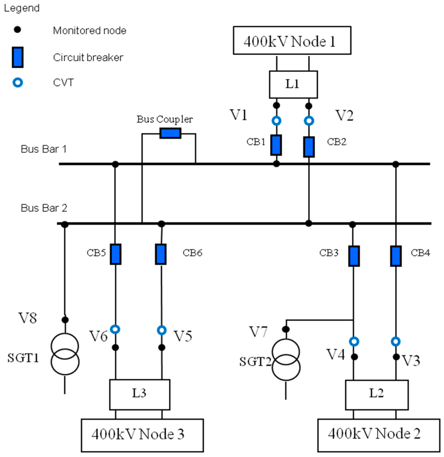
- Scenario A: a closing operation at the substation entry point (L1), where the substation feeds from Line 1 (L1), and:
- (ii).
- Scenario B: energization of a long line (L1), with the substation connected to the 400 kV network from the remaining Lines (L2 and L3).
7. Conclusions
Author Contributions
Funding
Conflicts of Interest
References
- Schaber, K.; Steinke, F.; Mühlich, P.; Hamacher, T. Parametric study of variable renewable energy integration in Europe: Advantages and costs of transmission grid extensions. Energy Policy 2012, 42, 498–508. [Google Scholar] [CrossRef] [Green Version]
- Preve, C.; Piccoz, D.; Maladen, R. Validation methods of SF6 alternative gas. In Proceedings of the 23rd Conference and Exhibition on Electricity Distribution (CIRED), Lyon, France, 15–18 June 2015; p. 493. [Google Scholar]
- Zhou, S.; Teng, F.; Tong, Q. Mitigating Sulfur Hexafluoride (SF6) Emission from Electrical Equipment in China. Sustainability 2018, 10, 2402. [Google Scholar] [CrossRef]
- Beroual, A.; Haddad, A. Recent Advances in the Quest for a New Insulation Gas with a Low Impact on the Environment to Replace Sulfur Hexafluoride (SF6) Gas in High-Voltage Power Network Applications. Energies 2017, 10, 1216. [Google Scholar] [CrossRef]
- Widger, P.; Haddad, A.M. Evaluation of SF6 Leakage from Gas Insulated Equipment on Electricity Networks in Great Britain. Energies 2018, 11, 2037. [Google Scholar] [CrossRef]
- IEC 60071-1. Insulation Co-Ordination—Part 1: Definitions, Principles and Rules; IEC Standards, Ed.8; IEC: Geneva, Switzerland, 2006. [Google Scholar]
- IEC 60071-2. Insulation Co-Ordination—Part 2 Application Guide; IEC Standards, Ed.; IEC: Geneva, Switzerland, 1996. [Google Scholar]
- National Grid Technical Specification, Substations, TS 2.01 Part 1—Issue 1; National Grid: London, UK, October 2014.
- National Grid UK. Relevant Electrical Standards; NGET; National Grid: London, UK, 9 January 2006. [Google Scholar]
- Davenport, W.M.W. Requirements and Specification of 400 kV Substations for C.E.G.B. Presented at the Design Criteria and Equipment for Transmission at 400 kV and Higher Voltages, London, UK, 27 September–1 October 1965; pp. 128–131. [Google Scholar]
- Paris, L.; Taschini, A.; Schneider, K.H.; Weck, K.H. Phase-to-ground and phase-to-phase air clearances in substations. ELECTRA 1973, 29, 29–44. [Google Scholar]
- Jones, B.; Waters, R.T. Air insulation at large spacings. Proc. IEE 1978, 125, 1152–1176. [Google Scholar] [CrossRef]
- Ullah, N.; Haddad, A.; German, D.M.; Tong, Y.K. Insulation coordination of compact substations. Presented at the 28th International Universities Power Engineering Conference (UPEC), Thessaloniki, Greece, 1–3 September 2003; pp. 105–108. [Google Scholar]
- Albano, M.; Haddad, A.; Griffiths, H.; Coventry, P. Performance of Compact Air Insulated Substations under Surge Conditions. In Proceedings of the ISH2011, Hannover, Germany, 22–26 August 2011. [Google Scholar]
- Albano, M.; Haddad, A.; Griffiths, H.; Coventry, P. Electric and magnetic fields in 400kV compact Substations. In Proceedings of the International Symposium on High Voltage Engineering—ISH 2009, Cape Town, South Africa, 24–28 August 2009. [Google Scholar]
- Albano, M.; Haddad, A.; Griffiths, H.; Coventry, P. Air insulated compact Substations. In Proceedings of the 43rd International Universities Power Engineering Conference—UPEC 2008, Padova, Italy, 1–4 September 2008; ISBN 978-88-89884-09-6. [Google Scholar]
- CIGRE Working Group A3.17. MO Surge Arresters Stresses and Test Procedures; Technical Brochures 544; CIGRE: Paris, France, August 2013. [Google Scholar]
- Andersson, P.-O.; Olovsson, H.-E.; Franzén, B.; Lager, U.; Lundquist, J. Applications of Disconnecting Circuit-Breakers; Report A3-201; Cigré Session: Paris, France, 2004. [Google Scholar]
- Rahmatian, F. High-voltage current and voltage sensors for a smarter transmission grid and their use in live-line testing and calibration. In Proceedings of the 2011 IEEE Power and Energy Society General Meeting, Detroit, MI, USA, 24–29 July 2011; pp. 1–3. [Google Scholar]
- Bohnert, K.; Gabus, P.; Brändle, H. Fiber-Optic Current and Voltage Sensors for high-Voltage Substations. In Proceedings of the 16th International Conference on Optical Fiber Sensors, Nara, Japan, 14–17 October 2003; pp. 752–754. [Google Scholar]
- ABB. 362–550 kV Disconnecting Circuit Breaker (DCB) with FOCS, Small, Smart and Flexible. Technical doc. 1HSM 9543 21-10en DCB with FOCS Edition 1, 2013–2003. Available online: www.abb.com (accessed on 20 December 2015).
- IEC 61850. Communication Networks and Systems for Power Utility Automation. Introduction and Overview; PD IEC/TR 61850-1:2013; IEC: Geneva, Switzerland, 2013. [Google Scholar]
- Ametani, A.; Kawamura, T. A method of a lightning surge analysis recommended in Japan using EMTP. IEEE Trans. Power Deliv. 2005, 20, 867–875. [Google Scholar] [CrossRef]
- Ametani, A. Lightning Surge Analysis by EMTP and Numerical Electromagnetic Analysis Method. In Proceedings of the International Conference on Lightning Protection (ICLP 2010), Cagliari, Italy, 13–17 September 2010. [Google Scholar]
- National Grid NGTS 3.2.3. Metal Oxide Surge Arresters; National Grid Technical Specification; National Grid: London, UK, December 2003. [Google Scholar]
- IEEE Working Group 15.08.09. Modeling and Analysis of System Transients Using Digital Programs—Part 1; IEEE PES Technical Report PES-TR7; IEEE: Piscataway, NJ, USA, 1998. [Google Scholar]
- IEEE Working Group 15.08.09. Modeling and Analysis of System Transients Using Digital Programs—Part 2; IEEE PES Technical Report PES-TR7; IEEE: Piscataway, NJ, USA, 1998. [Google Scholar]
- IEC 60071-4. Insulation Co-Ordination—Part 4: Computational Guide to Insulation Co-Ordination and Modelling of Electrical Networks; IEC Standards, Ed.1; IEC: Geneva, Switzerland, 2004. [Google Scholar]
- Watanabe, T.; Fukui, K.; Motoyama, H.; Noda, T. The measurement and analysis of surge characteristics using miniature model of air insulated substation. In Proceedings of the International Conference on Power Systems Transients (IPST 05), Montreal, QC, Canada, 19–23 June 2005. [Google Scholar]
- Ibrahim, I.; Dommel, H.W. A Knowledge Base for Switching Surge Transients. In Proceedings of the International Conference on Power Systems Transients, Montreal, QC, Canada, 19–23 June 2005. [Google Scholar]
- Martinez-Velasco, J.A. Power System Transients—Parameter Determination; CRC Press: Boca Raton, FL, USA, 2010. [Google Scholar]
- Canadian EMTP/ATP User Group. ATP Rule Book. 1987–1999; Canadian EMTP/ATP User Group: Portland, OR, USA, 4 January 2002. [Google Scholar]
- Al-Tai, M.A.; Elayyan, H.S.B.; German, D.M.; Haddad, A.; Harid, N.; Waters, R.T. The simulation of surge corona on transmission lines. IEEE Trans. Power Deliv. 1989, 4, 1360–1368. [Google Scholar] [CrossRef]


| Minimum Clearance | Existing Substation 1425/1050 kV [m] | Compact Substation 1050/850 KV [m] |
|---|---|---|
| phase-to-earth | 2.80 | 2.10 |
| phase-to-phase | 3.60 | 2.60 |
| Description | Existing Substation [m] | Compact Substation [m] |
|---|---|---|
| Minimum (Min.) clearances | ||
| C1—Min. phase-earth clearance | 2.80 | 2.10 |
| C2—Min. phase-phase clearance | 3.60 | 2.60 |
| Tolerance | ||
| T—Tool length (Safety tolerance) | 0.30 | 0.30 |
| PRv—Personal reach (vertical) | 2.40 | 2.40 |
| PRh—Personal reach (horizontal) | 1.50 | 1.50 |
| Safety | ||
| Safety Distance | 3.10 | 2.40 |
| SDv—Design clearance for safety (vertical) | 5.50 | 4.80 |
| SDh—Design clearance for safety (horizontal) | 4.60 | 3.90 |
| AIS Physical dimensions | ||
| a—Earthing frame height | 3.20 | 2.40 |
| b—Insulator height | 3.80 | 2.40 |
| c—Busbar phase separation | 5.00 | 2.67 |
| d—Bay side clearance | 3.60 | 2.17 |
| o—Busbar diameter | 0.14 | 0.14 |
| i—busbar center—ins. distance | 0.20 | 0.20 |
| h1—Buswork height (first layer) | 7.00 | 5.00 |
| Bay width | 17.48 | 10.39 |
| GIS Physical dimensions | GIS | |
| a—Earthing frame height | 3.00 | |
| c—Duct separation | 1.00 | |
| d—Bay side clearance | 2.10 | |
| o—GIS diameter | 0.14 | |
| i—GIS radius | 0.20 | |
| h1—GIS height | 7.00 | |
| Bay width | 6.80 |
| Busbar Arrangement | Bay Footprint Width (m) | Bay Height (m) |
|---|---|---|
| Existing design | 17.48 | 10.67 |
| Compact horizontal | 10.39 | 5.00 |
| Compact delta | 7.10 | 7.45 |
| Compact vertical | 5.34 | 15.47 |
| Compact vertical (cage) | 5.34 | 10.40 |
| GIS | 6.80 | 6.2 (to be indoor) |
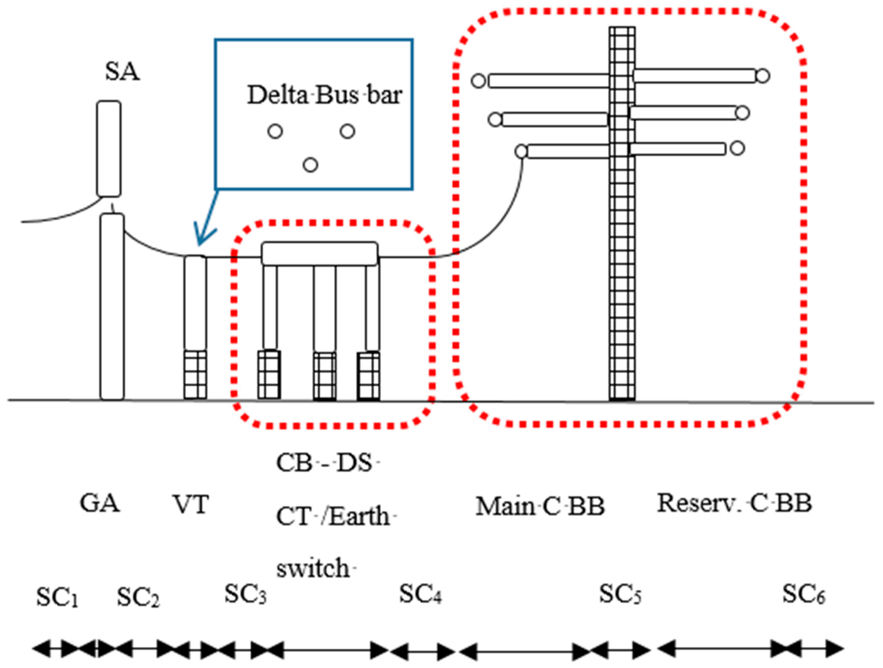
| Legend | Description | Component Length (m) | Component Clearance (m) |
|---|---|---|---|
| PLE | Point of Line Entry | 0 | 1.8 (S1, SC1) |
| GA | Gantry | 2.4 | 2.1 (S2, SC2) |
| SA | ZnO surge arrester | 1.4 | 3.35 (S3) |
| VT | Voltage transformer (conventional/non conventional) | 0.7 | 4.5 (S4, SC2) |
| DS/ESW | Disconnector isolator/earth switch | 5.3 | 1.7 (S5) |
| CT | Current transformer (conventional/non-conventional) | 0.9 | 2.1 (S6) |
| CB | Circuit breaker | 4.9 | 6.73 (S7, SC4) |
| Main BB | Main Busbar, including the isolator, vertical disconnector | 10.0 | 10.0 (S8) |
| Res. BB | Reserve busbar | 10.0 | 4.25 (S9) |
| Main C BB | Main Compact Busbar, includes the isolator, vertical disconnector | 1.5 | 4.5 (SC5) |
| Res. C BB | Reserve compact busbar | 1.5 | 4.25 (SC6) |
| Layout | Bay Length | Footprint Reduction | ||
|---|---|---|---|---|
| (m) | Diff% | (m2) | Diff% | |
| Conventional | 72 | 0% | 1241 | 0% |
| Proposed Compact design | 37 | 48% | 336 | 73% |
| Existing Substation LIWL 1425 kV-4.16 pu | Compact Substation LIWL 1050 kV-3.06 pu | |||
|---|---|---|---|---|
| pu | LIPM% | pu | LIPM% | |
| V1 (L1–c1) | 2.7 | 34% | 2.7 | 12% |
| V2 (L1–c2) | 2.5 | 39% | 2.4 | 21% |
| V3 (L2–c1) | 2.6 | 37% | 2.4 | 20% |
| V4 (L2–c2) | 2.6 | 37% | 2.4 | 22% |
| V5 (L3–c1) | 3.0 | 27% | 2.3 | 24% |
| V6 (L3–c2) | 2.9 | 31% | 2.3 | 24% |
| V7 (SGT2) | 2.4 | 40% | 2.4 | 21% |
| V8 (SGT1) | 2.4 | 41% | 2.4 | 21% |
| Scenario | Existing Substation SIWL 1050kV-3.06pu | Compact substation SIWL 850kV-2.48pu | ||
|---|---|---|---|---|
| pu | SIPM% | p. | SIPM% | |
| A | 2.2 | 27% | 2.4 | 3% |
| A-TP | 4.1 | np 1 | 4.3 | np 1 |
| A-SA | 2.9 | 5% | 2.2 | 12% |
| B | 2.7 | 12% | 2.7 | np 1 |
| B-TP | 4.1 | np 1 | 4.4 | np 1 |
| B-SA | 2.9 | 4% | 2.0 | 17% |
© 2018 by the authors. Licensee MDPI, Basel, Switzerland. This article is an open access article distributed under the terms and conditions of the Creative Commons Attribution (CC BY) license (http://creativecommons.org/licenses/by/4.0/).
Share and Cite
Albano, M.; Haddad, A.M.; Griffiths, H.; Coventry, P. Environmentally Friendly Compact Air-Insulated High-Voltage Substations. Energies 2018, 11, 2492. https://doi.org/10.3390/en11092492
Albano M, Haddad AM, Griffiths H, Coventry P. Environmentally Friendly Compact Air-Insulated High-Voltage Substations. Energies. 2018; 11(9):2492. https://doi.org/10.3390/en11092492
Chicago/Turabian StyleAlbano, Maurizio, A. Manu Haddad, Huw Griffiths, and Paul Coventry. 2018. "Environmentally Friendly Compact Air-Insulated High-Voltage Substations" Energies 11, no. 9: 2492. https://doi.org/10.3390/en11092492
APA StyleAlbano, M., Haddad, A. M., Griffiths, H., & Coventry, P. (2018). Environmentally Friendly Compact Air-Insulated High-Voltage Substations. Energies, 11(9), 2492. https://doi.org/10.3390/en11092492