Article

A Cost-Effective Decentralized Control for AC-Stacked Photovoltaic Inverters

1
School of Information Science and Engineering, Central South University, Changsha 410083, China
2
Department of Energy Technology, Aalborg University, DK-9220 Aalborg East, Denmark
*
Author to whom correspondence should be addressed.
Energies 2018, 11(9), 2262; https://doi.org/10.3390/en11092262
Submission received: 26 July 2018 / Revised: 23 August 2018 / Accepted: 24 August 2018 / Published: 28 August 2018
(This article belongs to the Special Issue Microgrids-2018)

Abstract

:
For an AC-stacked photovoltaic (PV) inverter system with N cascaded inverters, existing control methods require at least N communication links to acquire the grid synchronization signal. In this paper, a novel decentralized control is proposed. For N inverters, only one inverter nearest the point of common coupling (PCC) needs a communication link to acquire the grid voltage phase and all other N − 1 inverters use only local measured information to achieved fully decentralized local control. Specifically, one inverter with a communication link utilizes the grid voltage phase and adopts current control mode to achieve a required power factor (PF). All other inverters need only local information without communication links and adopt voltage control mode to achieve maximum power point tracking (MPPT) and self-synchronization with grid voltage. Compared with existing methods, the communication link and complexity is greatly reduced, thus improved reliability and reduced communication costs are achieved. The effectiveness of the proposed control is verified by simulation tests.

1. Introduction

Renewable energy generation is drawing more and more attention in the past decades [1,2,3,4,5]. AC-stacked photovoltaic (PV) inverter architecture is now considered a promising PV generation configuration [6,7,8,9,10,11,12]. It facilitates the integration of low voltage (LV) PV generators into medium/high voltage (MV/HV) grid due to its AC-stacked characteristic. LV PV generation units can be connected to the MV/HV grid directly by the AC-stacked PV inverters with no need for a step-up transformer, which leads to improved energy conversion efficiency. Compared with the traditional multilevel cascaded H-bridge topology, each AC-stacked PV inverter has an independent output LC filter, which makes it much easier for coordinating all PV inverter units [6,7]. In this way, distributed control methods or even fully decentralized control methods are much easier to implement, which means the communication complexity is much lower and the system’s reliability is higher. In this way, the AC-stacked PV inverter system has great potential for large-scale MV/HV grid-connected distributed PV generation. So, to explore new decentralized control methods with min-communication requirement for AC-stacked inverters makes a lot of sense. And the motivation of this paper is to propose a min-communication decentralized control for AC-stacked PV inverters.
Recently, some low-bandwidth communication-based controls for AC-stacked PV inverters have been investigated [8,9,10,11,12]. In Reference [8], a distributed autonomous control is first proposed without a central controller. Grid voltage phase from a phase locked loop (PLL) is transmitted to all inverters to realize synchronization and maximum power point tracking (MPPT) operation by low-bandwidth communications. However, reactive power and power factor (PF) control are not discussed. To realize flexible power control and satisfactory PF, distributed active power and reactive power control methods are improved in Reference [9], where all AC-stacked inverters are controlled in voltage mode. Furthermore, references [10,11] propose a hybrid current-voltage control scheme with low-bandwidth communication. In References [5,6], one inverter in the AC-stacked PV inverter string is controlled as a current source to serve as a reactive power compensation unit and other inverters are controlled as voltage sources. A controllable PF is achieved by this hybrid control framework. Different from References [8,9,10,11], each AC-stacked inverter string has a central controller to coordinate all local controllers of inverters in Reference [12]. The voltage phase reference of each inverter is generated by combining the common current phase and the transmitted power factor from central controller. As the transmitted information is a slow DC component, a low-bandwidth communication link is required for each inverter.
Although existing control methods achieve MPPT and PF regulation, they all require at least N communication links for N inverters to acquire the synchronization signal from grid references [8,9,10,11,12]. As a result, system reliability is limited by high communication complexity. On the other hand, increased communication cost is unavoidable. Similar to the need to explore distributed/decentralized control approaches to solving the optimal power flow problem in power system references [13,14], how to design a decentralized control algorithm for AC-stacked PV inverters is necessary.
In view of the overview above, this paper proposes a min-communication decentralized control method to greatly improve system reliability and lower the communication cost. The contributions of the proposed control method are listed as follows:
(1)
It reduces the communication links to a great extent compared with existing control methods. Only one communication link is needed. Thus, system reliability is greatly improved and communication cost is reduced;
(2)
It achieves voltage self-synchronization with grid voltage with no need for PLL;
(3)
It can achieve a desirable unity PF or a required non-unity PF;
(4)
It achieves MPPT of all cascaded inverters under symmetrical conditions and partial shading;
(5)
It is available under grid voltage sag and grid frequency fluctuation.
The rest of this paper is organized as follows: In Section 2, the system configuration is described and the mathematical model of the AC-stacked PV inverter system is derived. In Section 3, the proposed control method is presented and analyzed in detail. In Section 4, simulation results under different conditions are provided to verify the effectiveness of the proposed control. Conclusions are finally drawn in Section 5. To make this paper clearer, variables and parameters used in this paper are listed in the nomenclature below.

2. System Modeling

The configuration of the AC-stacked PV inverter system studied in this paper is shown in Figure 1. The whole system consists of n series-connected PV inverter units, where each inverter has an independent output LC filter. These AC-stacked inverters are then connected to the utility grid directly without a step-up transformer. In each PV inverter unit, local PV panels are directly tied to the input port of an inverter. This type of system architecture aims to integrate LV distributed PV generators into the power grid directly with high energy conversion efficiency. Moreover, this topology makes it possible for distributed or decentralized control to be realized since output of each inverter is at AC line frequency.
In Figure 1, V1~Vn and δ1n are amplitudes and phase angles of the inverters’ output voltages. Vg and δg represent amplitude and phase angle of the grid voltage, respectively. Vp and δp are voltage amplitude and phase at the PCC. Lline is the line inductance, its amplitude and angle are denoted as |Lline| and θline. iPV1~iPVn and udc1~udcn represent the PV output currents and PV output voltages. L1~Ln and C1~Cn are the parameters of output LC filters. From Figure 1, the output active power and reactive power of i-th (i = 1, 2, …, n) inverter, which are denoted as Pi and Qi, can be calculated as
P i = Re { V i e j δ i   2 ( V p e j δ p V g e j δ g | L l i n e | e j θ l i n e ) * }
Q i = Im { V i e j δ i   2 ( V p e j δ p V g e j δ g | L l i n e | e j θ l i n e ) * }
There is a factor 1/2 in Equations (1) and (2) because Vi, Vp and Vg are all amplitude values, instead of RMS (Root Mean Square) values. For this AC-stacked PV inverter architecture, the voltage at the PCC is the sum of u1~un:
V p e j δ p   = j = 1 n V j e j δ j
By substitution of Equation (3) into Equations (1) and (2), Pi and Qi are derived as
P i = j = 1   n V i V j 2 | Z l i n e | cos ( δ l i n e + δ i δ j ) V i V g 2 | Z l i n e | cos ( δ l i n e + δ i δ g )
Q i = j = 1   n V i V j 2 | Z l i n e | sin ( δ l i n e + δ i δ j ) V i V g 2 | Z l i n e | sin ( δ l i n e + δ i δ g )

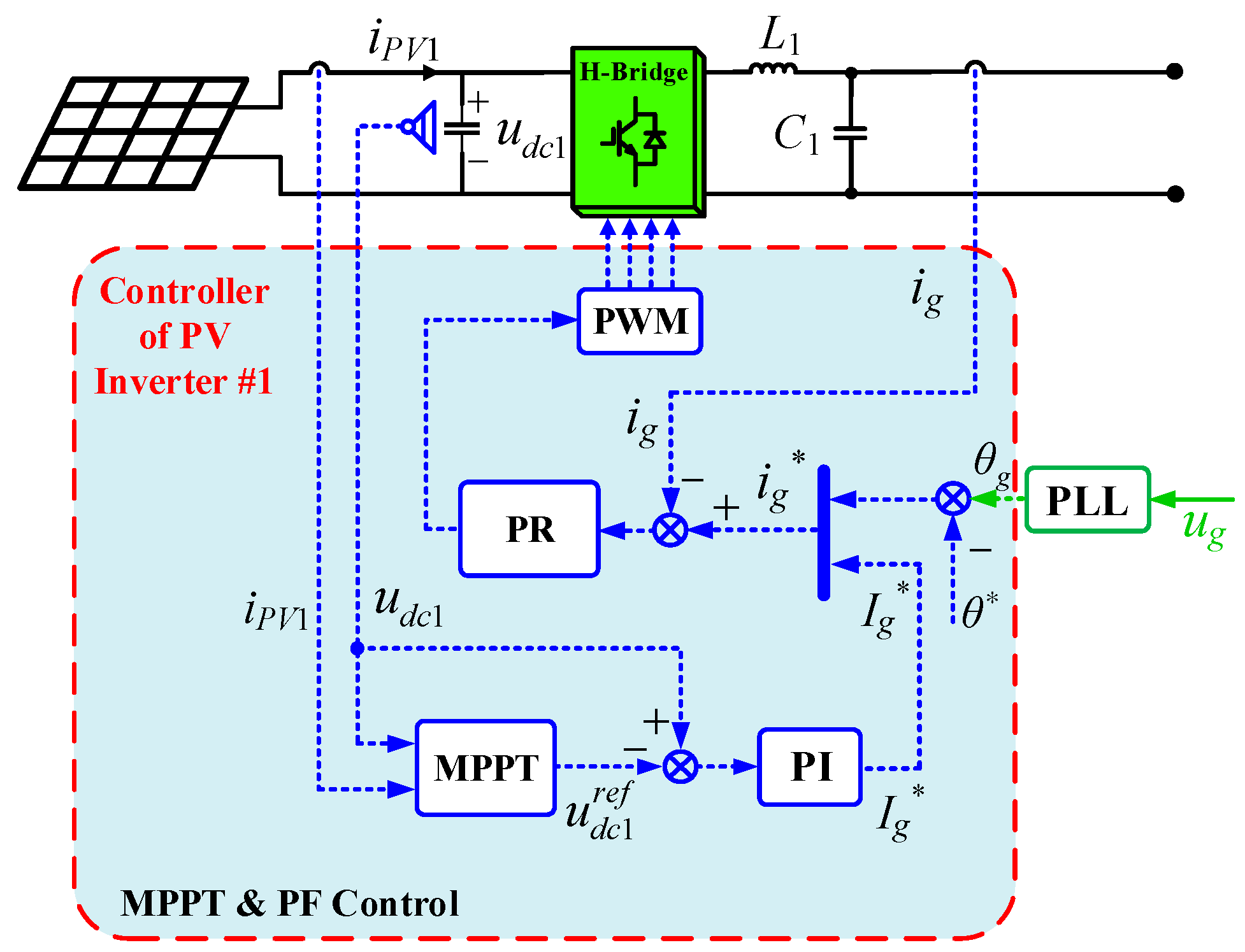
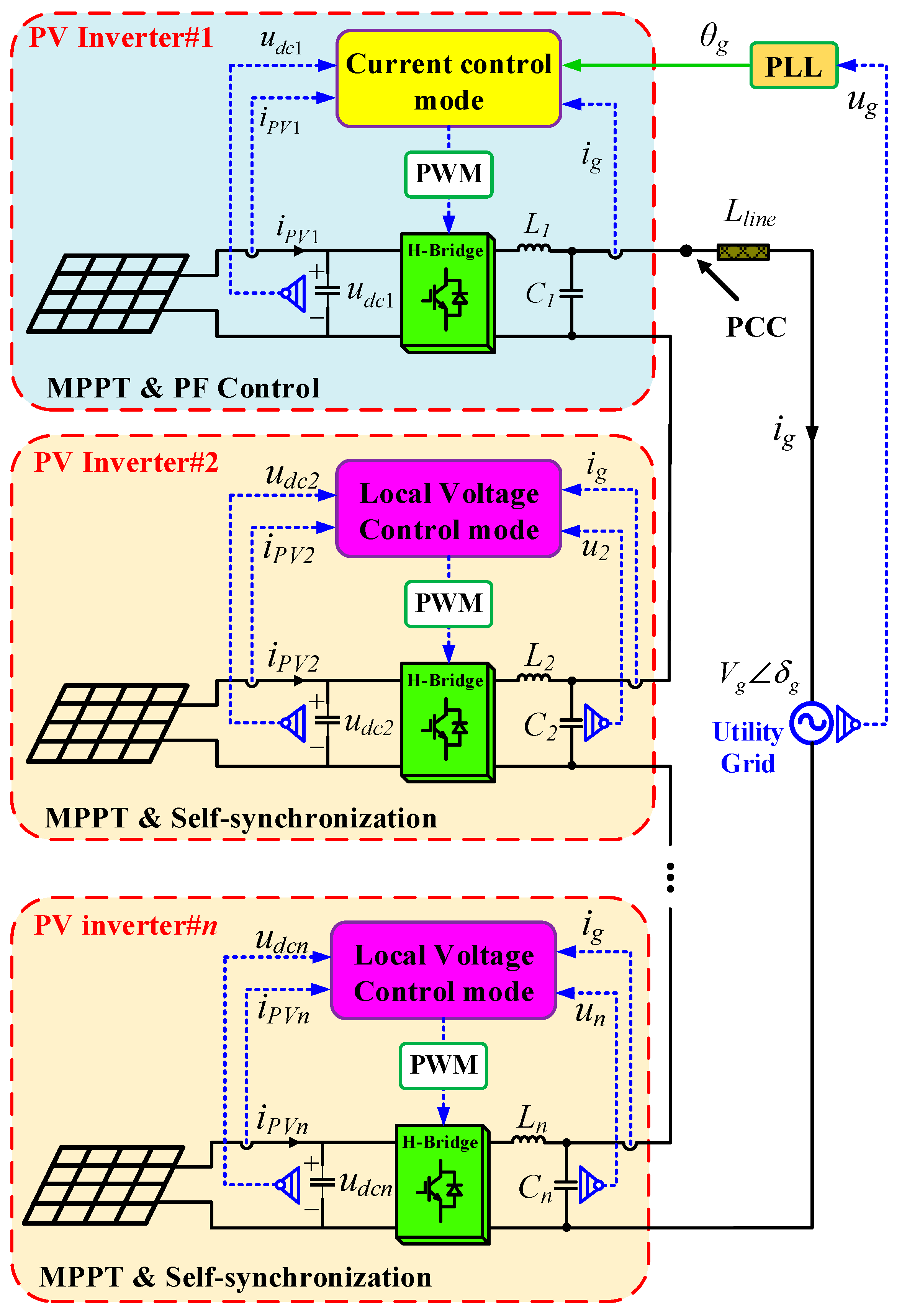
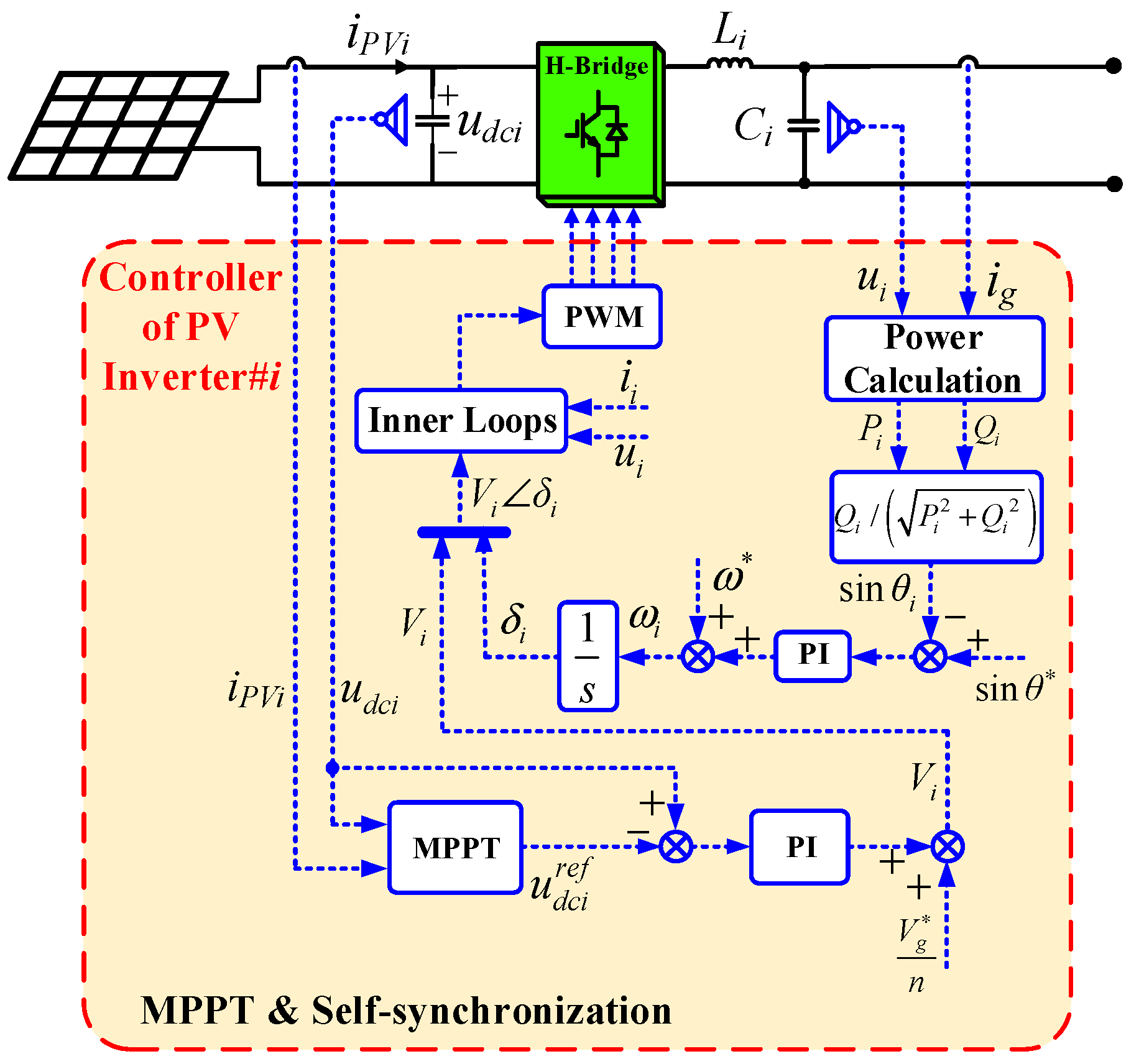
3. Proposed Decentralized Control

3.1. Schematic Overview of the Proposed Decentralized Control

The overall schematic overview of the proposed decentralized control is presented in Figure 2. It is noted that only one communication link is needed to transmit the grid voltage phase to inverter#1. Inverter#1 is controlled as a current source to carry out PF regulation and track its maximum power point (MPP). Inverter#1 can achieve a desired PF according to practical requirements. All other inverters are controlled as voltage sources locally and independently to achieve MPPT and self-synchronization. They need only local information and they need no grid synchronization signal.

3.2. Proposed Decentralized Control

The control diagram of inverter#1 is shown in Figure 3. Inverter#1 is controlled as a current source to serve as a current regulation unit for the AC-stacked PV inverter string while tracking its MPP. The front-end DC-link voltage reference u d c 1 r e f is provided by the MPPT controller. In order to realize the desired PF, the line current phase reference is determined by the grid voltage phase θg from a PLL. Then the output current reference i g is synthesized by I g , θ and θg. θ is the system PF angle, which is set according to the practical PF requirement. Thus, the proposed method can achieve different PFs by setting different values of θ . Finally, the line current is regulated to its reference value by a proportional (PR) controller.
For inverter#i (i = 2, 3, …, n), the detailed control diagram is presented in Figure 4. Inverter#i is responsible for building up the voltage at the PCC while outputting its maximum power available. The proposed control for inverter#i aims to achieve self-synchronization and MPPT without communication links. As shown in Figure 4, the core of proposed control is designed as
{ V i = V g   n + ( K P i + K I i s ) ( u d c i u d c i r e f ) ω i = ω + ( k P i + k I i s ) ( sin θ sin θ i ) ( i = 2 , 3 , , n )
where Vi and ωi represent the output voltage amplitude reference and angular frequency reference of inverter#i respectively. Vg and ω* are the rated grid voltage amplitude and rated grid angular frequency. udci is the front-end DC-link voltage of inverter#i and u d c i r e f is the DC-link voltage reference provided by MPPT controller. KPi and KIi are the proportional and integral (PI) coefficients of the DC-link voltage controller. θi and θ* are real-time PF angle of inverter#i and its reference. θ* can be flexibly set according to the system PF requirement. KPi and KIi are the proportional and integral coefficients of the frequency controller. The designed frequency controller can realize frequency self-synchronization with the grid frequency.
As the DC-link voltage controller is a PI regulator, Vi can be regulated autonomously to form the voltage at the PCC and match the grid voltage. In this way, the proposed method is adaptable even when grid voltage sag happens. Additionally, Equation (7) must hold in steady state:
u d c i   = u d c i r e f
Equation (7) reveals that MPPT operation is ensured in steady state. On the other hand, Equation (8) must hold in steady-state:
ω i = ω  
In other words, Equation (9) must hold to reach a steady state:
( k P i   + k I i s ) ( sin θ sin θ i ) = 0
Since frequency controller is a PI controller, Equation (10) must hold in steady state.
sin θ = sin θ i  
This indicates that the frequency of each inverter will be synchronous with grid frequency in a steady state and the output voltage of each inverter will be in phase with grid voltage in a steady state. Moreover, From Equations (6)–(10) and Figure 4, MPPT of inverter#i is achieved by regulating its output voltage amplitude and self-synchronization with grid voltage is achieved by adjusting the output angular frequency according to its own PF angle. No communication links are involved and PLL is not needed.

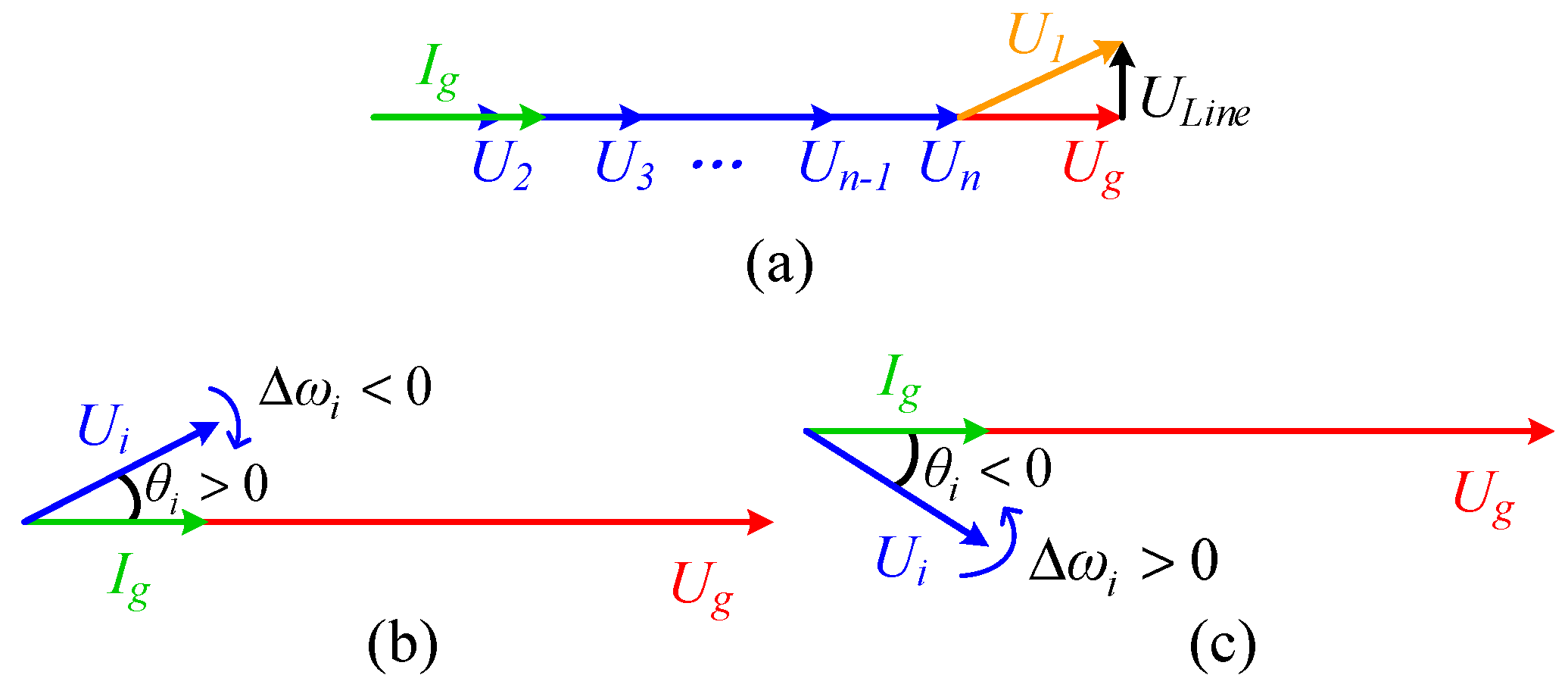
3.3. Steady-State Analysis and Self-Synchronization Mechanism

According to the description in Section 3.2, the proposed method is adaptable under grid voltage sag and grid frequency fluctuation. On the other hand, it can also meet different PF requirements. In practical PV grid-connected applications, unity PF is often required. So, we take the unity PF condition as an example to analyze the control mechanism. Similar analysis can also be adapted in other non-unity PF conditions.
With the proposed control for PV inverter#1, the line current is regulated and becomes in phase with the grid voltage in steady state to satisfy the unity PF requirement. As the line current is a common signal for all the AC-stacked PV inverters, inverter#i (i = 2, 3, ..., n) can thus self-synchronize its output voltage with the grid voltage indirectly by synchronizing its output voltage with the line current locally. So, we set sinθ* = 0 in Equation (6) for inverter#i to synchronize with grid voltage under unity PF operation requirement.
The detailed self-synchronization mechanism in Equation (6) can be illustrated by Figure 5.
  • Initially, the system is operating in steady-state. The steady-state phasor diagram is shown in Figure 5a. Output voltages of inverter#2~inverter#n, line current and the grid voltage are all in phase in a steady state. Small amount of reactive power consumed by the line impedance is compensated by inverter#1 and unity PF of this grid-connected system is ensured;
  • When disturbances occur, power angle of inverter#i will change. For example, θi > 0 as shown in Figure 5b. According to Equation (6), the angular frequency reference ω i = ( ω k i sin θ i ) < ω . And thus the relative angular frequency between ui and ug is: Δ ω i = ( ω i ω ) = k i sin θ i < 0 ;
  • As a result, θi will decrease until θi = 0 and self-synchronization of inverter#i is achieved;
  • Similar analysis can be applied to the condition where θi < 0 occurs as shown in Figure 5c. From the analysis above, self-synchronization of ui with the grid voltage ug is achieved with the proposed control.

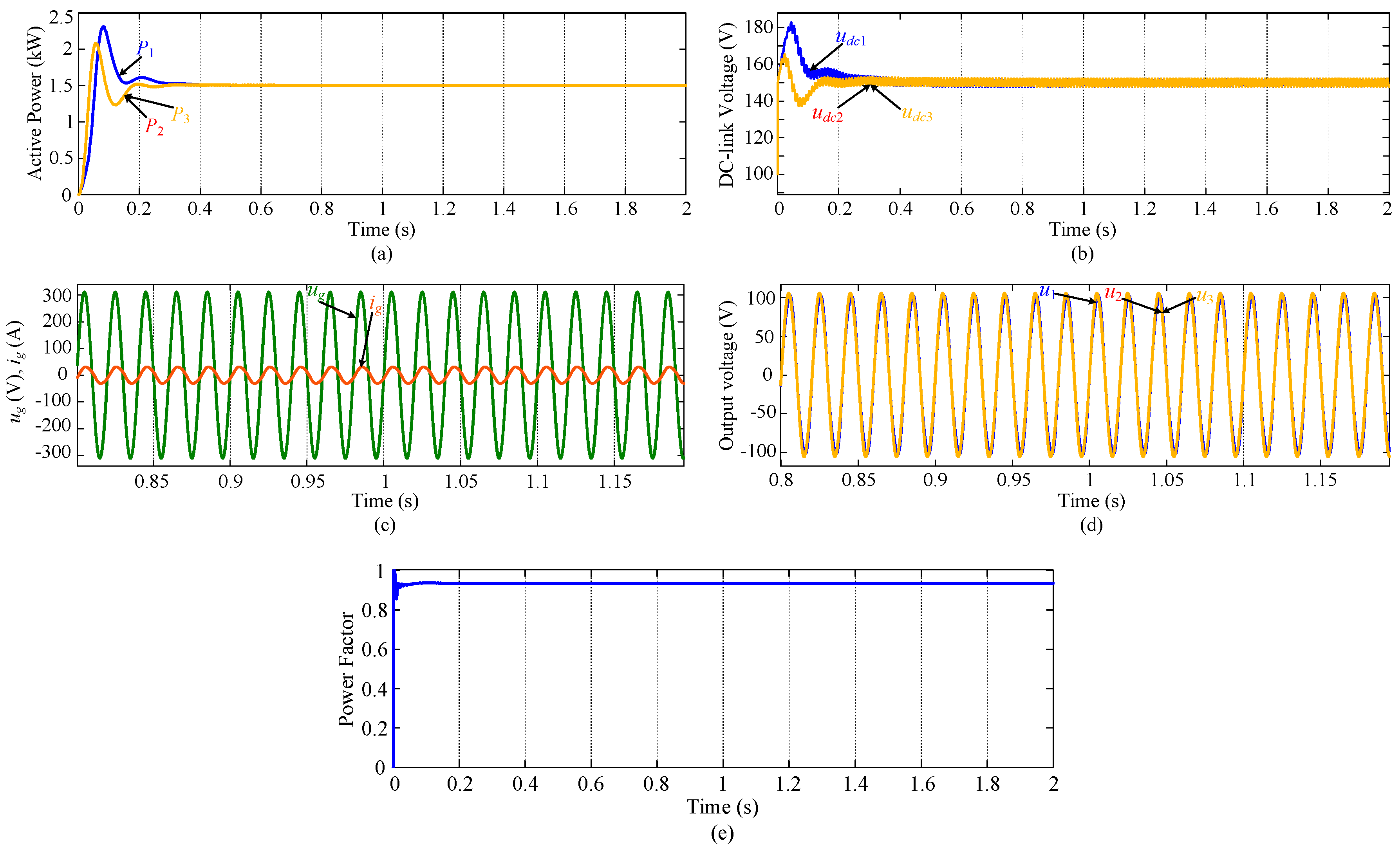
4. Simulation Results

To verify the correctness and effectiveness of the proposed control method, four simulation tests in different operation conditions are conducted. The simulation model consists of three AC-stacked PV inverters. Simulation parameters are listed in Table 1.

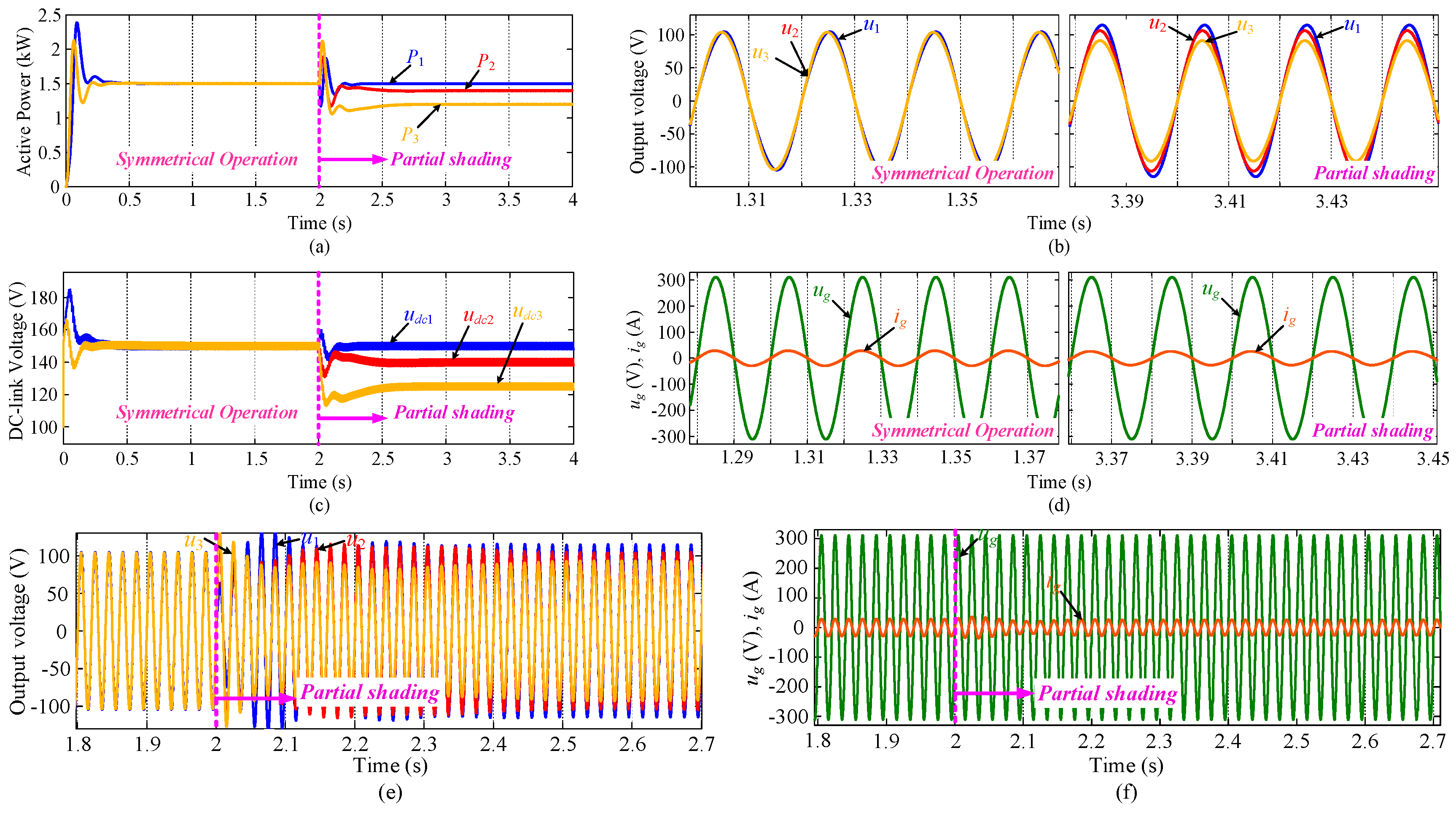
4.1. Symmetrical Condition and Partial Shading

To evaluate the steady-state and dynamic performances of the proposed control, both symmetrical condition and partial shading condition are simulated. Before t = 2s, the symmetrical operation condition is simulated. At t = 2s, different partial shadings are imposed on PV inverter#2 and PV inverter#3 simultaneously. Simulation results are shown in Figure 6.
Before t = 2s, the output active power of the inverters P1, P2 and P3 are equal in Figure 6a, since the system operates under symmetrical conditions. In Figure 6c, steady-state DC-link voltages of all the inverters are the same, which indicates all PV inverter units operates at MPP. In Figure 6b, output voltages of inverter#2 and inverter#3 are identical, while output voltage of inverter#1 is a little different to compensate the line reactive power. After t = 2s, P2 drops from 1500 W to 1400 W and P3 drops to 1200 W while P1 stays unchanged in Figure 6a, because different shadings are imposed on inverter#2 and inverter#3 simultaneously. The DC-link voltages udc2 and udc3 drop to different steady-state values accordingly, shown in Figure 6c, still operating at the MPP. In Figure 6b, u2 and u3 are still in phase while their amplitudes are different, owing to their different maximum power outputs. In addition, amplitude of u1 is the highest, because it generates the highest active power and compensates the line reactive power to regulate system PF. Figure 6d shows that the line current and grid voltage are always in phase in different steady states. So, unity PF of the system is achieved in both symmetrical and partial shading conditions. Moreover, the steady-state line current amplitude after t = 2s is smaller than the current amplitude before t = 2s, since total active power injected to the grid is smaller when partial shading happens. Output voltages in transient states are shown in Figure 6e, the output voltages of the inverters response immediately according to the control algorithm in Equation (6). Grid voltage and line current in transient states are presented in Figure 6f. It is clear that the amplitude of the transient line current transient is not too high and the phase angle of line current is also in phase with the grid voltage. So, required unity PF is ensured in the transient state.

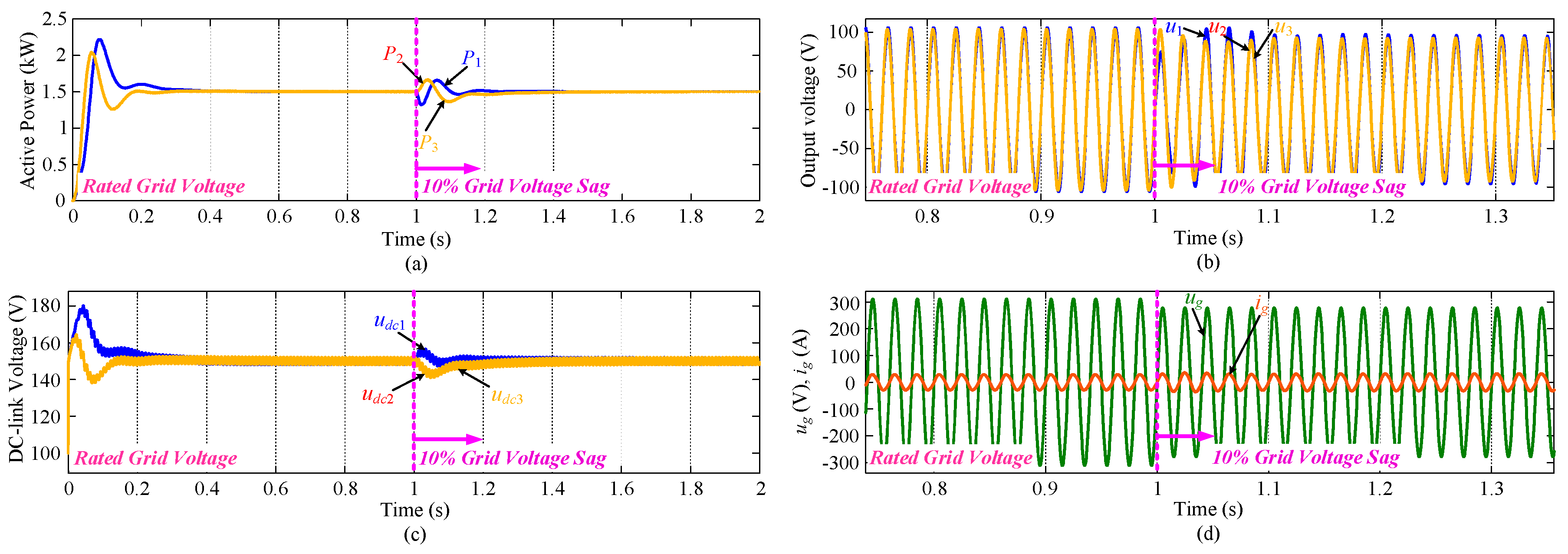
4.2. Grid Voltage Sag Condition

To demonstrate the feasibility of the proposed method under grid faults, a simulation test under 10% grid voltage sag is carried out. Before t = 1s, the system operates under rated grid voltage condition. At t = 1s, 10% grid voltage sag is simulated. Simulation results are shown in Figure 7.
From Figure 7a,c P1~P3 are identical and DC-link voltages udc1~udc3 reach the same steady-state value during t = 0~1s, which indicates that the system operates under symmetrical conditions and achieves MPPT. In Figure 7b, output voltages of inverter#2 and inverter#3 are identical before t = 1s, while output voltage of inverter#1 is a little different to compensate for the line reactive power. Figure 7d shows that grid voltage and line current are inphase and a satisfactory unity PF is achieved, where the grid voltage is at its rated value. At t = 1s, 10% grid voltage sag is implemented which can be seen in Figure 7d. During this process, output voltage of inverter#1 reacts immediately to compensate for the grid voltage sag as shown in Figure 7b. Meanwhile, inverter#2 and inverter#3 reduce their output voltage amplitudes gradually according to Equation (6). Eventually, u1~u3 reach new steady-state values to match the sagged grid voltage. In Figure 7d, the amplitude of line current increases to a higher steady-state value after t = 1s to maintain the maximum active power output of all PV inverters and line current is still inphase with the grid voltage to satisfy unity PF requirement. From Figure 7a,c the steady-state values of P1~P3 and DC-link voltages udc1~udc3 stay unchanged after t = 1s despite 10% grid voltage sag. So, MPPT operation of all PV inverters are still ensured and self-synchronization of inverter#2 and inverter#3 are realized. Thus, the proposed method is immune to the grid voltage fault.

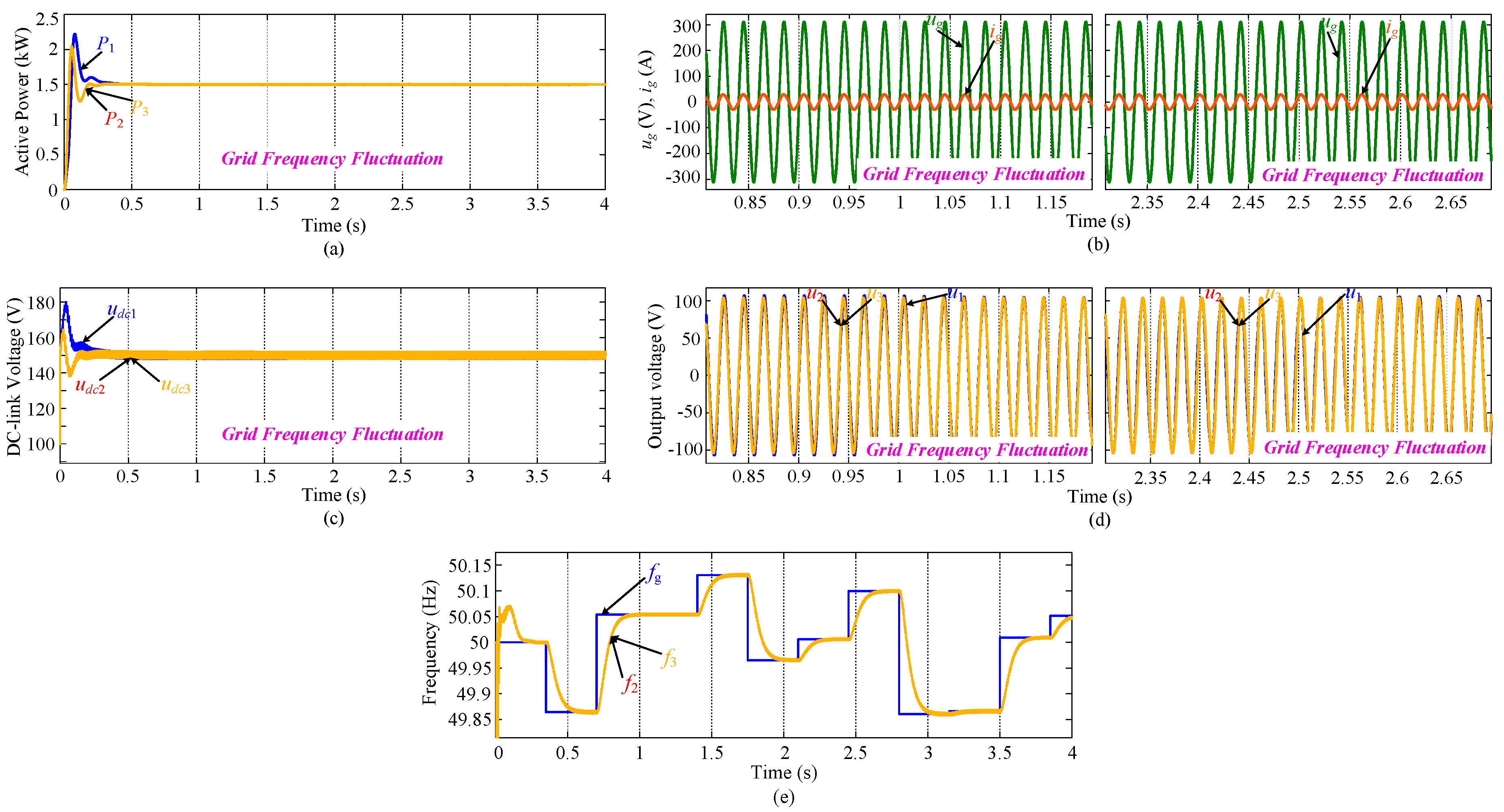
4.3. Grid Frequency Fluctuation Condition

To verify the feasibility of the proposed method under grid frequency fluctuation, a simulation test with random grid frequency variation is performed. Initially, the system operates under rated grid frequency condition. Then random frequency fluctuation is simulated. Simulation results are shown in Figure 8.
From Figure 8a,c P1~P3 are identical and DC-link voltages udc1~udc3 reach the same steady-state value, which indicates that the system operates under symmetrical condition and achieves MPPT. In Figure 8d, output voltages of inverter#2 and inverter#3 are identical, while output voltage of inverter#1 is a little different to compensate the line reactive power. Figure 8b shows that grid voltage and line current are inphase and a desired unity PF is achieved. The frequencies of the system are shown in Figure 8e. In the beginning, grid frequency is the rated value. f2f3 are 50 Hz tracking the rated grid frequency. Then, grid frequency varies randomly. Accordingly, f2f3 follow to change and track the real-time grid frequency tightly. Thus, the proposed control method is adaptable to the grid frequency fluctuation and can self-synchronize the inverters’ frequencies with the grid frequency. So, the proposed control method can maintain the stability of the system even when grid frequency fluctuation occurs.

4.4. No-Unity PF Operation

In most gird-connected PV generation applications, unity PF is required. However, no-unity PF and Volt/Var capability of the inverters are required. To verify the PF controllability of the proposed method, a simulation test with a required PF = 0.92 is performed. To achieve PF = 0.92, we just need to set θ* = 0.4027 in Equation (6). Simulation results are shown in Figure 9.
From Figure 9a,b P1~P3 are identical and DC-link voltages udc1~udc3 reach the same steady-state value, which indicates that the system operates under symmetrical condition and achieves MPPT. In Figure 9d, output voltages of inverter#2 and inverter#3 are identical, while output voltage of inverter#1 is a little different to compensate the line reactive power. Figure 9c shows that grid voltage and line current are not inphase and a no-unity PF is achieved. The system PF is shown Figure 9e. Obviously, the required PF = 0.92 is achieved.
From the simulation results and analysis above, we can see the advantages and performances of the proposed control method clearly. For an AC-stacked PV inverter system with N inverters, the main advantages and performances of the proposed control method in comparison with the existing control methods are summarized in Table 2.

5. Conclusions

This paper proposes a one-communication-link decentralized control for AC-stacked PV inverter system. It achieves the following objectives:
(1)
It reduces the communication complexity to a great extent compared with existing control methods. Specifically, it reduces N − 1 communication links for a system with N inverters. Thus system reliability is greatly improved and communication cost is reduced;
(2)
It achieves voltage self-synchronization with grid voltage;
(3)
It can achieve a desirable unity PF or a required non-unity PF;
(4)
It achieves MPPT of all cascaded inverters under symmetrical conditions and partial shading;
(5)
It is available under grid voltage sag and grid frequency fluctuation.
Simulation tests under symmetrical/partial-shading condition, grid voltage sag condition, grid frequency fluctuation condition and non-unity PF requirement condition have verified the effectiveness of the proposed control method. Beyond this study, the possibilities of new ideas will be inspired in future cascaded-type distributed generation systems.
For better operation of the AC-stacked PV inverter system in practical application situation, seeking for optimal configuration of the energy storage system in this architecture and corresponding control methods with high reliability are very important and meaningful. This aspect will be explored in our future work.

Author Contributions

C.L. conceived the main idea and wrote the manuscript with guidance from X.H. and H.H.; W.Y. and Z.L. performed the simulations; M.S. and J.M.G. reviewed the work and gave helpful improvement suggestions.

Funding

This work was supported by the National Natural Science Foundation of China under Grant 61573384 and Grant 51677195, and the Fundamental Research Funds for the Central Universities of Central South University under Grant 2018zzts531.

Conflicts of Interest

The authors declare no conflict of interest.

Nomenclature

udciDC-link voltage of i-th inverter
iPViPV current of i-th inverter
LlineLine inductance
CDCiCapacitor in DC side
igLine current
V g δ g Grid voltage
i g Line current reference
u d c r e f DC-Link voltage reference
θiPower angle of i-th inverter
V g Rated grid voltage amplitude
ω*Rated grid frequency
ViOutput voltage amplitude reference of i-th inverter
ωiAngular frequency of i-th inverter
uiOutput voltage amplitude of i-th inverter
KPi, KIiProportional and integral coefficients of DC voltage controller
kPi, kIiProportional and integral coefficients of frequency controller

References

  1. Hou, X.; Sun, Y.; Han, H.; Liu, Z.; Yuan, W.; Su, M. A fully decentralized control of grid-connected cascaded inverters. IEEE Trans. Power Del. 2018. [Google Scholar] [CrossRef]
  2. Sun, Y.; Hou, X.; Yang, J.; Han, H.; Su, M.; Guerrero, J.M. New perspectives on droop control in AC microgrid. IEEE Trans. Ind. Electron. 2017, 64, 5741–5745. [Google Scholar] [CrossRef]
  3. Hou, X.; Sun, Y.; Han, H.; Liu, Z.; Su, M.; Wang, B.; Zhang, X. A General Decentralized Control Scheme for Medium/High Voltage Cascaded STATCOM. IEEE Trans. Power Syst. 2018. [Google Scholar] [CrossRef]
  4. Liu, Z.; Su, M.; Sun, Y.; Li, L.; Han, H.; Zhang, X.; Zheng, M. Optimal criterion and global/sub-optimal control schemes of decentralized economical dispatch for AC microgrid. Int. J. Electr. Power Energy Syst. 2019, 104, 38–42. [Google Scholar] [CrossRef]
  5. Li, L.; Ye, H.; Sun, Y.; Han, H.; Li, X.; Su, M.; Guerrero, J.M. A communication-free economical-sharing scheme for cascaded-type microgrids. Int. J. Electr. Power Energy Syst. 2019, 104, 1–9. [Google Scholar] [CrossRef]
  6. Nuotio, M.; Ilic, M.; Liu, Y.; Bonanno, J.; Verlinden, P.J. Innovative AC photovoltaic module system using series connection and universal low-voltage micro inverters. In Proceedings of the 2014 IEEE 40th Photovoltaic Specialist Conference (PVSC), Denver, CO, USA, 8–13 June 2014; pp. 1367–1369. [Google Scholar]
  7. Bhowmik, S. Systems and Methods for Solar Photovolatic Energy Collection and Conversion. U.S. Patent 9,531,293, 27 December 2016. [Google Scholar]
  8. Lu, F.; Choi, B.; Maksimovic, D. Autonomous control of series-connected low voltage photovoltaic microinverters. In Proceedings of the 2015 IEEE 16th Workshop on Control and Modeling for Power Electronics (COMPEL), Vancouver, BC, Canada, 12–15 July 2015; pp. 1–6. [Google Scholar]
  9. Zhang, L.; Sun, K.; Li, Y.W.; Lu, X.; Zhao, J. A Distributed Power Control of Series-connected Module Integrated Inverters for PV Grid-tied Applications. IEEE Trans. Power Electron. 2017, 7698–7707. [Google Scholar] [CrossRef]
  10. Jafarian, H.; Cox, R.; Enslin, J.H.; Bhowmik, S.; Parkhideh, B. Decentralized Active and Reactive Power Control for an AC-Stacked PV Inverter with Single Member Phase Compensation. IEEE Trans. Ind. Appl. 2018, 54, 345–355. [Google Scholar] [CrossRef]
  11. Jafarian, H.; Bhowmik, S.; Parkhideh, B. Hybrid Current-/Voltage-Mode Control Scheme for Distributed AC-Stacked PV Inverter with Low-Bandwidth Communication Requirements. IEEE Trans. Ind. Electron. 2018, 65, 321–330. [Google Scholar] [CrossRef]
  12. He, J.; Li, Y.; Wang, C.; Pan, Y.; Zhang, C.; Xing, X. Hybrid Microgrid With Parallel- and Series-Connected Microconverters. IEEE Trans. Power Electron. 2018, 33, 4817–4831. [Google Scholar] [CrossRef]
  13. Hadi Amini, M.; Bahrami, S.; Kamyab, F.; Mishra, S.; Jaddivada, R.; Boroojeni, K.; Weng, P.; Xu, Y. Decomposition Methods for Distributed Optimal Power Flow: Panorama and Case Studies of the DC Model. Class. Recent Asp. Power Syst. Optim. 2018, 137–155. [Google Scholar] [CrossRef]
  14. Mohammadi, A.; Mehrtash, M.; Kargarian, A. Diagonal Quadratic Approximation for Decentralized Collaborative TSO+DSO Optimal Power Flow. IEEE Trans. Smart Grid. 2018, 1. [Google Scholar] [CrossRef]
Figure 1. Configuration of AC-stacked photovoltaic (PV) inverter system.
Energies 11 02262 g001
Figure 2. Overall control framework of the proposed method.
Energies 11 02262 g002
Figure 3. Control diagram of inverter#1.
Energies 11 02262 g003
Figure 4. Control diagram of inverter#i (i = 2, 3, …, n).
Energies 11 02262 g004
Figure 5. (a) Steady-state phasor diagram; (b) Self-synchronization process of inverter#i when θi > 0; (c) Self-synchronization process of inverter#i when θi < 0.
Energies 11 02262 g005
Figure 6. Simulation results under symmetrical condition and partial shading condition. (a) Active power; (b) Steady-state output voltages; (c) DC-link voltages; (d) Grid voltage and line current in steady state; (e) Output voltages in transient state; (f) Grid voltage and line current in transient state.
Energies 11 02262 g006
Figure 7. Simulation results under 10% grid voltage sag condition. (a) Active power; (b) Steady-state output voltages; (c) DC-link voltages; (d) Grid voltage and line current in steady state.
Energies 11 02262 g007
Figure 8. Simulation results under grid frequency fluctuation. (a) Active power; (b) Grid voltage and line current; (c) DC-link voltages; (d) Output voltages; (e) Frequencies.
Energies 11 02262 g008
Figure 9. Simulation results under grid frequency fluctuation. (a) Active power; (b) DC-link voltages; (c) Grid voltage and line current; (d) Output voltages; (e) Power factor (PF).
Energies 11 02262 g009
Table 1. Simulation Parameters.
SymbolValueSymbolValue
Vg311 VKP2 = KP31.8
ω*2π × 50 rad/sKI2 = KI36
sinθ*0 & 0.392kP2 = kP37
Lline300 μHkI2 = kI30.2
CDC1= CDC2= CDC34000 μF--
Table 2. Comparison with Existing Control Methods.
ItemsProposed Decentralized ControlExisting Control Methods
Number of Communication Links1N
Communication CostLowHigh
Communication ComplexityLowHigh
Reliability in Case of Communication FaultsHighLow
Synchronization MethodBy Self-synchronization MechanismBy Centralized Communication
Global MPPT OperationYesYes
Operation Under Grid Voltage SagYesYes
Operation Under Grid Frequency FluctuationYesYes

