A Distribution Static Compensator Using a CFNN-AMF Controller for Power Quality Improvement and DC-Link Voltage Regulation


Abstract
1. Introduction
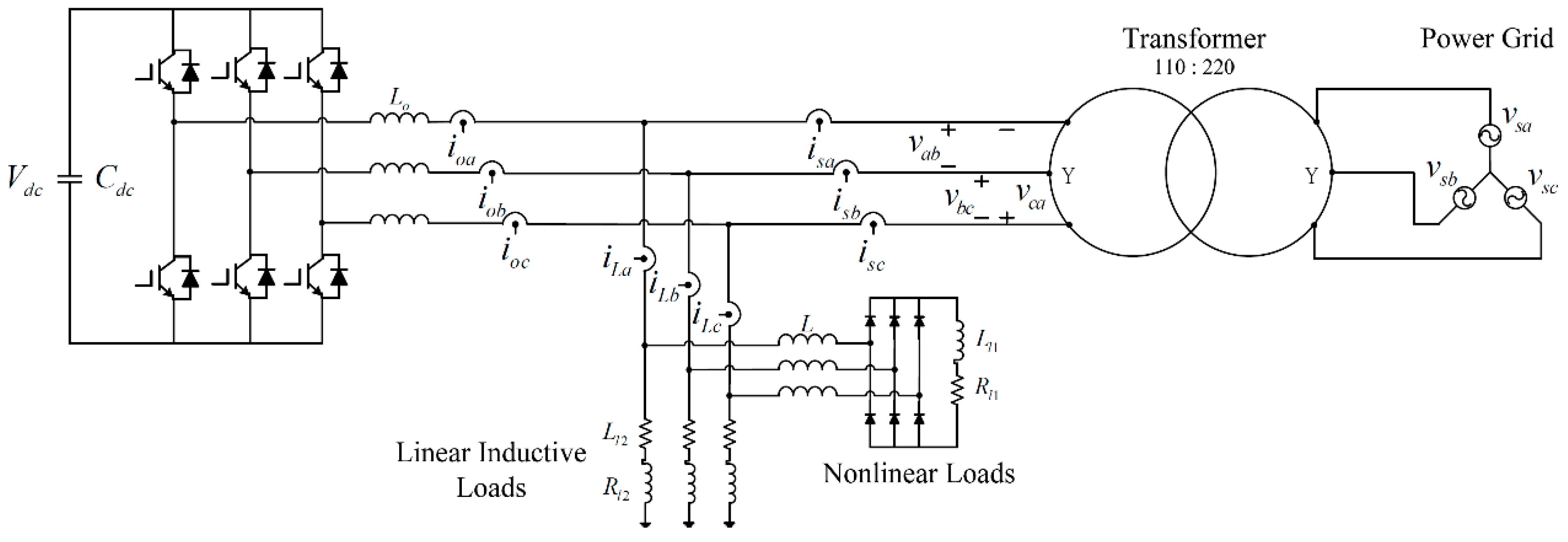
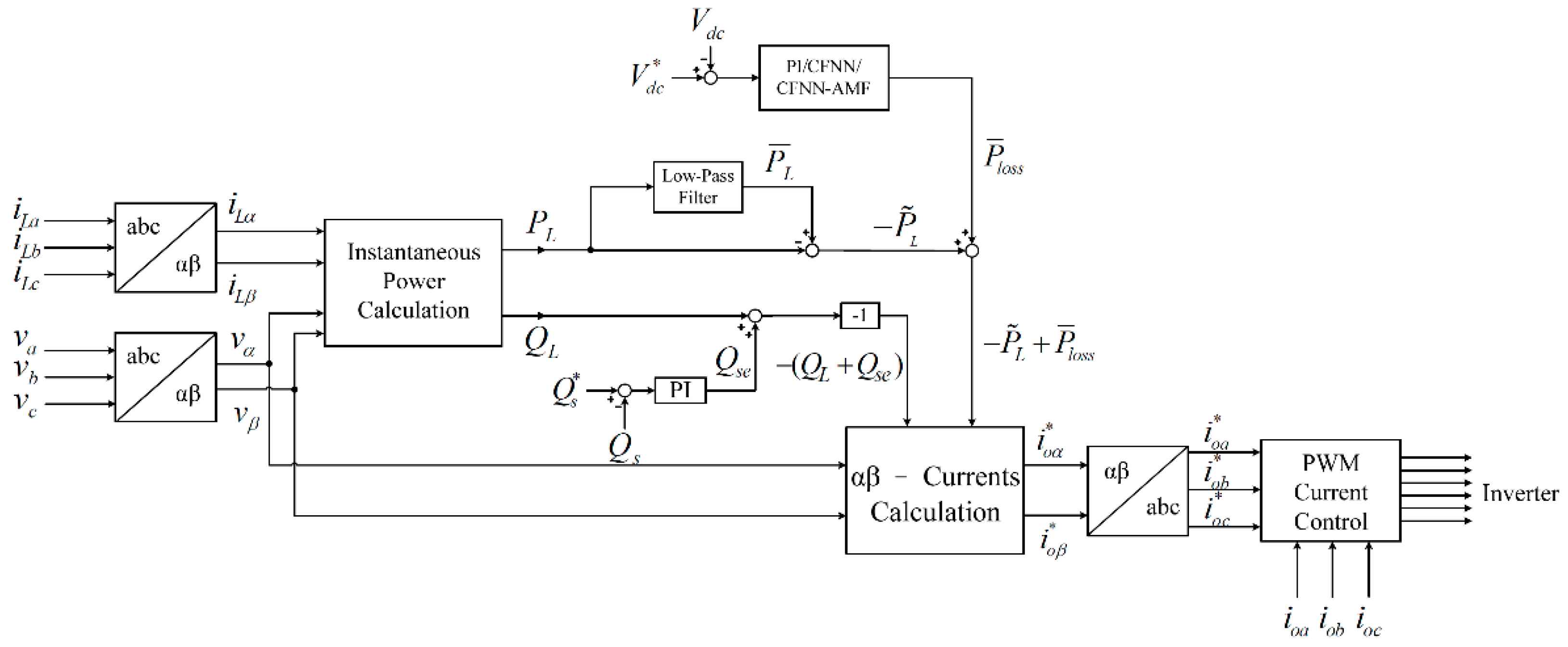
2. DSTATCOM
3. Intelligent CFNN-AMF Controller
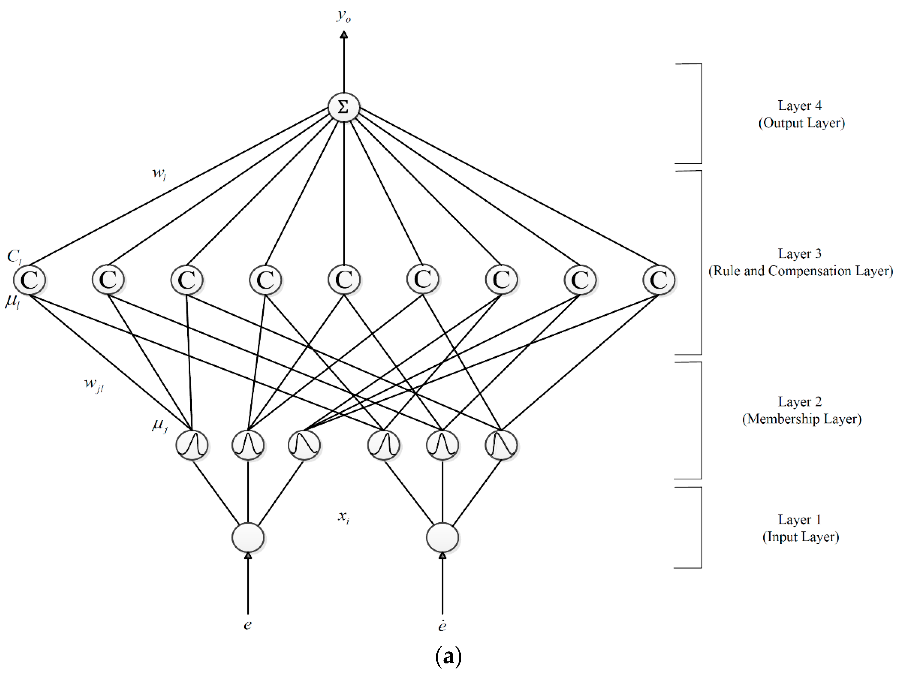
3.1. Network Architecture
3.2. Online Learning Algorithm
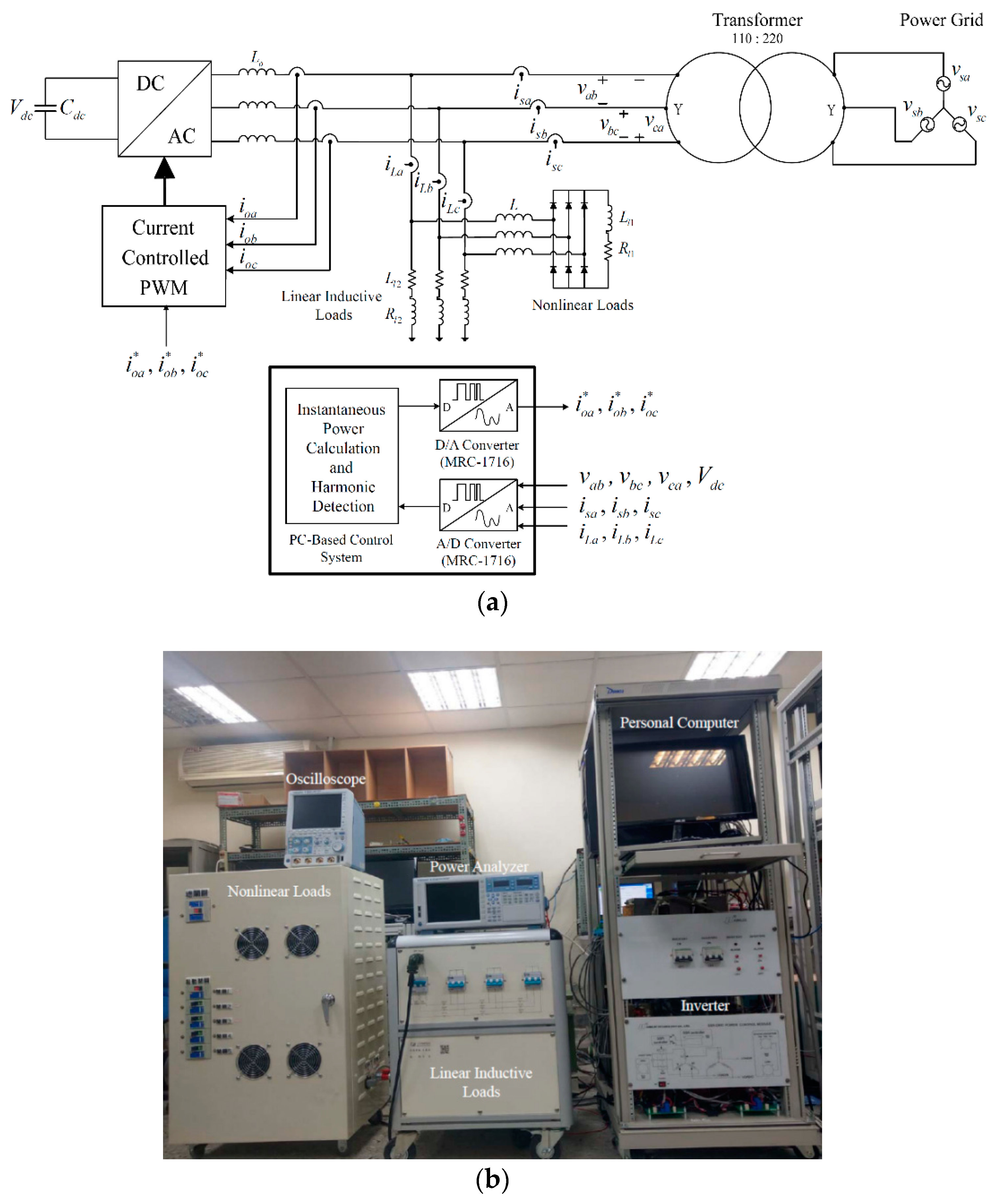
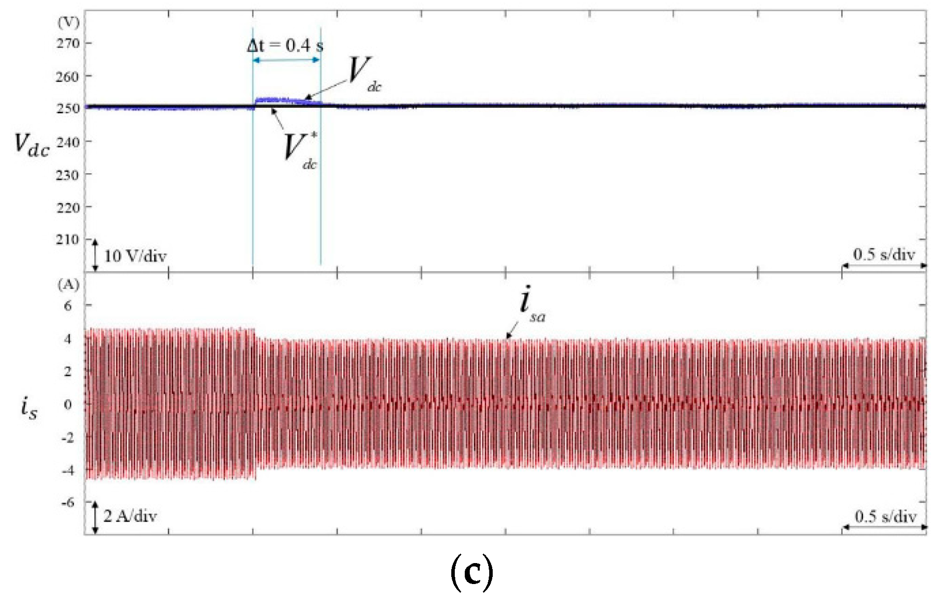
4. Experimental Results
5. Conclusions
Author Contributions
Funding
Conflicts of Interest
References
- Mishra, S.; Ray, P.K. Power quality improvement using photovoltaic fed DSTATCOM based on JAYA optimization. IEEE Trans. Sustain. Energy 2016, 7, 1672–1680. [Google Scholar] [CrossRef]
- Sekhar, V.C.; Kant, K.; Singh, B. DSTATCOM supported induction generator for improving power quality. IET Renew. Power Gener. 2016, 10, 495–503. [Google Scholar] [CrossRef]
- Srinivas, M.; Hussain, I.; Singh, B. Combined LMS–LMF-based control algorithm of DSTATCOM for power quality enhancement in distribution system. IEEE Trans. Ind. Electron. 2016, 63, 4160–4168. [Google Scholar] [CrossRef]
- Chittora, P.; Singh, A.; Singh, M. Performance evaluation of digital filters in distribution static compensator for non-linear loads. IET Power Electron. 2017, 10, 1915–1923. [Google Scholar] [CrossRef]
- Tan, K.H.; Lin, F.J.; Chen, J.H. Three-phase four-leg inverter-based APF for unbalanced current compensation using PPFNN. Energies 2017, 10, 2005. [Google Scholar] [CrossRef]
- Latran, M.B.; Teke, A.; Yoldaş, Y. Mitigation of power quality problems using distribution static synchronous compensator: A comprehensive review. IET Power Electron. 2015, 8, 1312–1328. [Google Scholar] [CrossRef]
- Elnady, A.; Salama, M.M.A. Unified approach for mitigating voltage sag and voltage flicker using the DSTATCOM. IEEE Trans. Power Deliv. 2005, 20, 992–1000. [Google Scholar] [CrossRef]
- Singh, B.; Arya, S.R.; Jain, C. Simple peak detection control algorithm of distribution static compensator for power quality improvement. IET Power Electron. 2014, 7, 1736–1746. [Google Scholar] [CrossRef]
- Venkatraman, K.; Selvan, M.P.; Moorthi, S. Predictive current control of distribution static compensator for load compensation in distribution system. IET Gener. Transm. Distrib. 2016, 10, 2410–2423. [Google Scholar] [CrossRef]
- Singh, B.; Solanki, J. A comparison of control algorithms for DSTATCOM. IEEE Trans. Ind. Electron. 2009, 56, 2738–2745. [Google Scholar] [CrossRef]
- Kumar, A.P.; Mangaraj, M. DSTATCOM employing hybrid neural network control technique for power quality improvement. IET Power Electron. 2017, 10, 480–489. [Google Scholar] [CrossRef]
- Biricik, S.; Redif, S.; Ozerdem, Ö.C.; Khadem, S.K.; Basu, M. Real-time control of shunt active power filter under distorted grid voltage and unbalanced load condition using self-tuning filter. IET Power Electron. 2014, 7, 1895–1905. [Google Scholar] [CrossRef]
- Acuña, P.; Morán, L.; Rivera, M.; Dixon, J.; Rodriguez, J. Improved active power filter performance for renewable power generation systems. IEEE Trans. Power Electron. 2014, 29, 687–694. [Google Scholar] [CrossRef]
- Arya, S.R.; Singh, B.; Niwas, R.; Chandra, A.; Al-Haddad, K. Power quality enhancement using DSTATCOM in distributed power generation system. IEEE Trans. Ind. Appl. 2016, 52, 5203–5212. [Google Scholar] [CrossRef]
- Pandey, R.; Tripathi, R.N.; Hanamoto, T. Comprehensive analysis of LCL filter interfaced cascaded H-bridge multilevel inverter-based DSTATCOM. Energies 2017, 10, 346. [Google Scholar] [CrossRef]
- Roncero-Sánchez, P.; Acha, E. Design of a control scheme for distribution static synchronous compensators with power-quality improvement capability. Energies 2014, 7, 2476–2497. [Google Scholar] [CrossRef]
- Somsai, K.; Kulworawanichpong, T. Instantaneous power control of D-STATCOM with consideration of power factor correction. In Proceedings of the 2010 ECTI International Confernce on Electrical Engineering/Electronics, Computer, Telecommunications and Information Technology, Chiang Mai, Thailand, 19–25 May 2010; pp. 1186–1190. [Google Scholar]
- Zhang, Y.Q.; Kandel, A. Compensatory neurofuzzy systems with fast learning algorithm. IEEE Trans. Neural Netw. 1998, 9, 83–105. [Google Scholar] [CrossRef] [PubMed]
- Seker, H.; Evans, D.H.; Aydin, N.; Yazgan, E. Compensatory fuzzy neural networks-based intelligent detection of abnormal neonatal cerebral Doppler ultrasound waveforms. IEEE Trans. Inf. Technol. Biomed. 2001, 5, 187–194. [Google Scholar] [CrossRef] [PubMed]
- Lin, C.H.; Chen, C.H. Identification and prediction using recurrent compensatory neuro-fuzzy systems. Fuzzy Sets Syst. 2005, 150, 307–330. [Google Scholar] [CrossRef]
- Lin, F.J.; Hung, Y.C.; Tsai, M.T. Fault-tolerant control for six-phase PMSM drive system via intelligent complementary sliding-mode control using TSKFNN-AMF. IEEE Trans. Ind. Electron. 2013, 60, 5747–5762. [Google Scholar] [CrossRef]
- Lin, F.J.; Lu, K.C.; Ke, T.H.; Yang, B.H.; Chang, Y.R. Reactive power control of three-phase grid-connected PV System during grid faults using Takagi–Sugeno–Kang probabilistic fuzzy neural network control. IEEE Trans. Ind. Electron. 2015, 62, 5516–5528. [Google Scholar] [CrossRef]
- Ouyang, C.S.; Lee, S.J. An improved learning algorithm for rule refinement in neuro-fuzzy modeling. In Proceedings of the 1999 Third International Conference on Knowledge-Based Intelligent Information Engineering Systems. Proceedings (Cat. No. 99TH8410), Adelaide, Australia, 31 August–1 September 1999; pp. 238–241. [Google Scholar]
- Institute of Electrical and Electronics Engineers (IEEE). IEEE Recommended Practice and Requirements for Harmonic Control in Electric Power Systems; IEEE: Piscataway, NJ, USA, 2014. [Google Scholar]


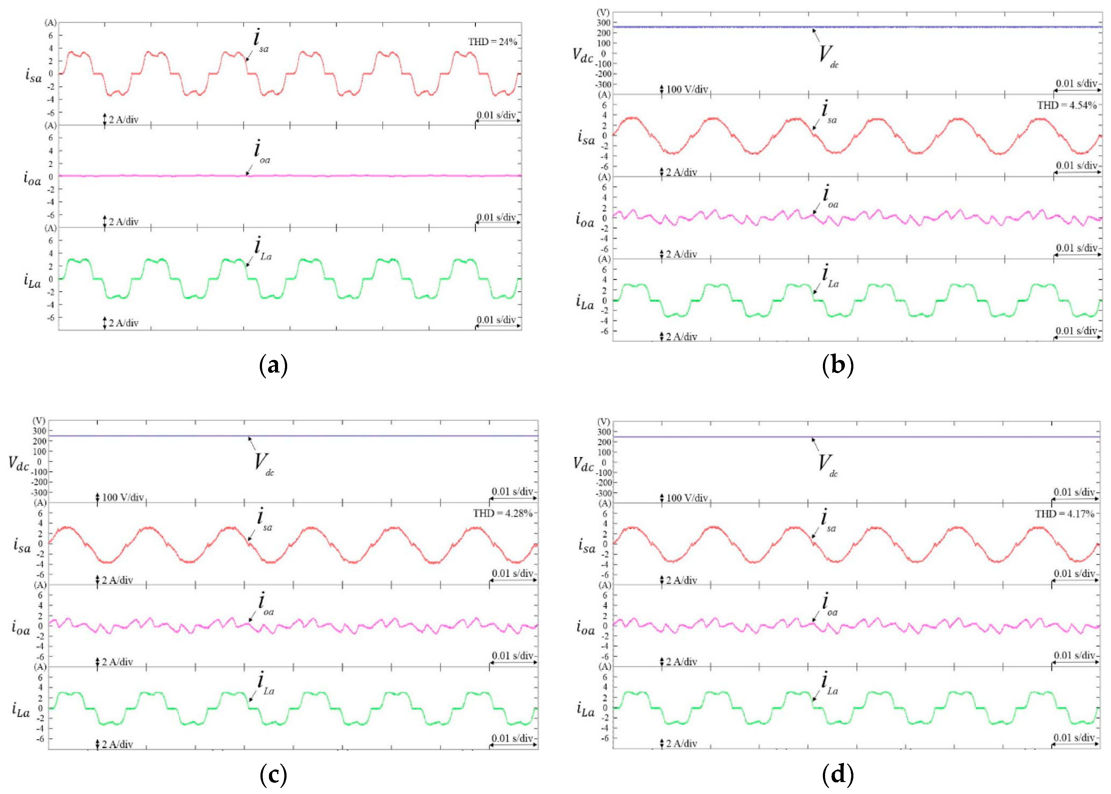
| Active Compensation | DC-Link Controllers | THD of Phase-A Grid Current (%) | ||
|---|---|---|---|---|
| Nonlinear Load 1 | Nonlinear Load 2 | Nonlinear Load 3 | ||
| Without DSTATCOM | - | 26 | 25.27 | 24 |
| DSTATCOM | PI | 4.83 | 4.61 | 4.54 |
| DSTATCOM | CFNN | 4.56 | 4.43 | 4.28 |
| DSTATCOM | CFNN-AMF | 4.45 | 4.22 | 4.17 |
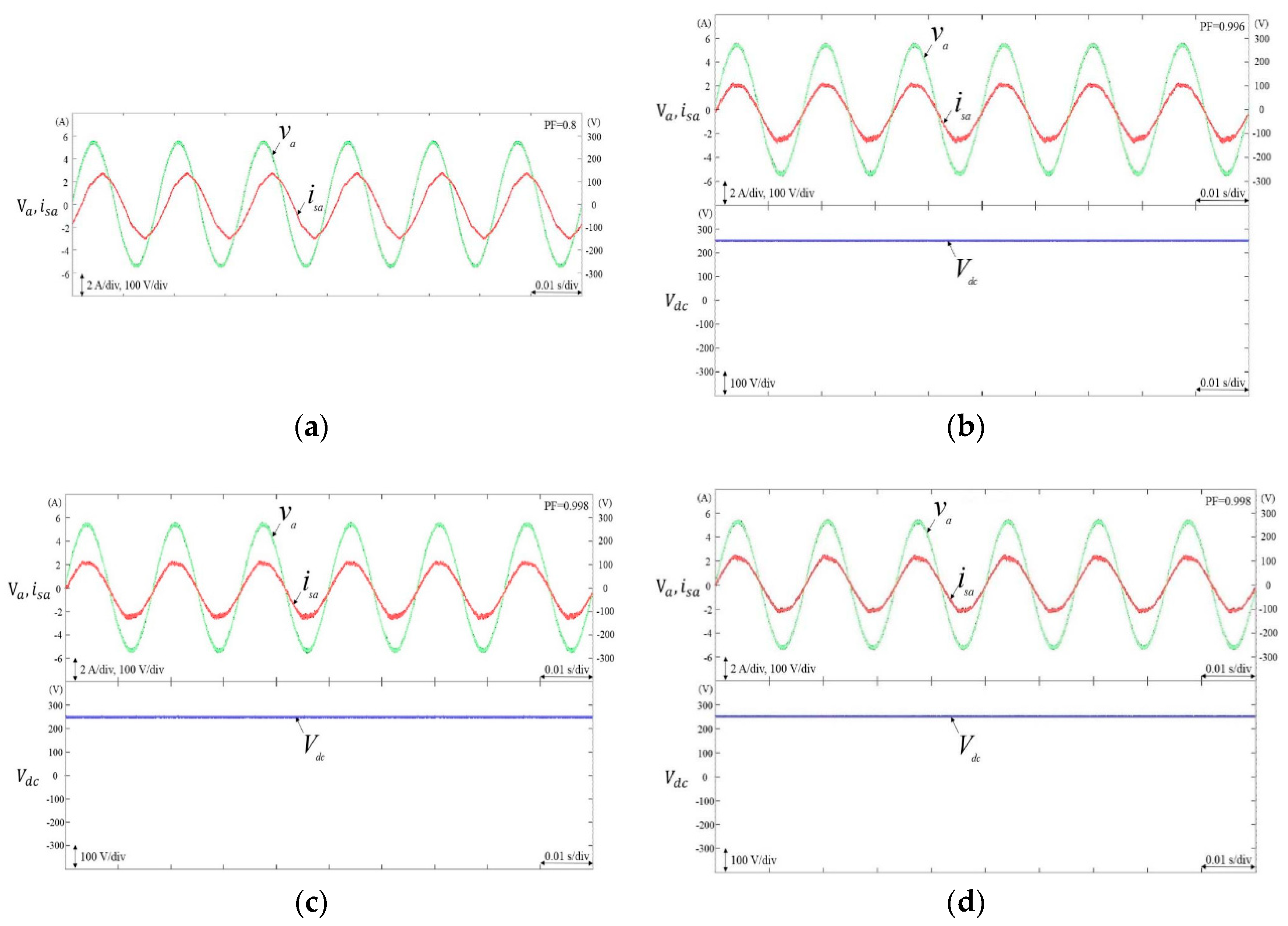
| Active Compensation | DC-Link Controllers | Power Factor (PF) | ||
|---|---|---|---|---|
| Linear Inductive Load 1 | Linear Inductive Load 2 | Linear Inductive Load 3 | ||
| Without DSTATCOM | - | 0.912 | 0.856 | 0.8 |
| DSTATCOM | PI | 0.997 | 0.997 | 0.996 |
| DSTATCOM | CFNN | 0.998 | 0.998 | 0.998 |
| DSTATCOM | CFNN-AMF | 0.999 | 0.998 | 0.998 |
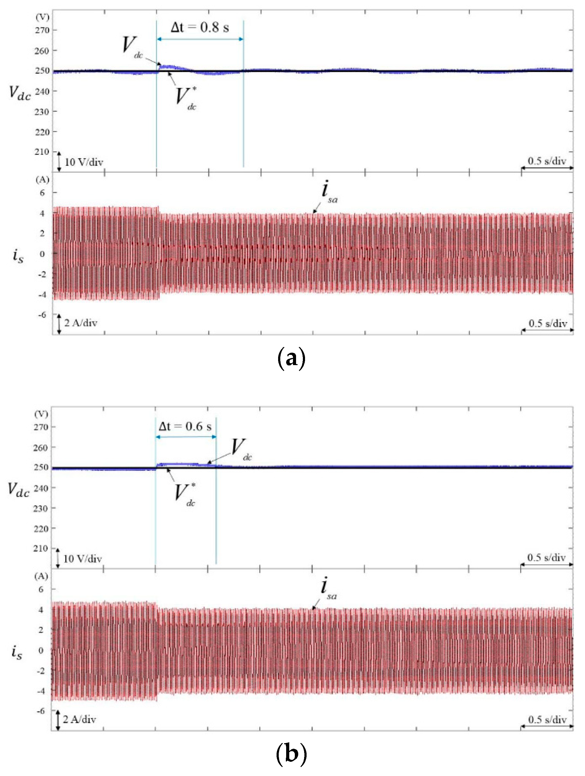
| Case Condition | DC-Link Controllers | Response Time (s) | Overshoot to Undershoot (V) |
|---|---|---|---|
| Nonlinear Load 1 → Nonlinear Load 3 | Nonlinear Load 1 → Nonlinear Load 3 | ||
| Case 1 | PI | 2 | 9.6 |
| CFNN | 1.35 | 8.3 | |
| CFNN-AMF | 1 | 7.9 |
| Case Condition | DC-Link Controllers | Response Time (s) | Overshoot to Undershoot (V) |
|---|---|---|---|
| Linear Inductive Load 1 → Linear Inductive Load 3 | Linear Inductive Load 1 → Linear Inductive Load 3 | ||
| Case 2 | PI | 0.8 | 5 |
| CFNN | 0.6 | 4 | |
| CFNN-AMF | 0.4 | 3.6 |
© 2018 by the authors. Licensee MDPI, Basel, Switzerland. This article is an open access article distributed under the terms and conditions of the Creative Commons Attribution (CC BY) license (http://creativecommons.org/licenses/by/4.0/).
Share and Cite
Tan, K.-H.; Lin, F.-J.; Tsai, C.-Y.; Chang, Y.-R. A Distribution Static Compensator Using a CFNN-AMF Controller for Power Quality Improvement and DC-Link Voltage Regulation. Energies 2018, 11, 1996. https://doi.org/10.3390/en11081996
Tan K-H, Lin F-J, Tsai C-Y, Chang Y-R. A Distribution Static Compensator Using a CFNN-AMF Controller for Power Quality Improvement and DC-Link Voltage Regulation. Energies. 2018; 11(8):1996. https://doi.org/10.3390/en11081996
Chicago/Turabian StyleTan, Kuang-Hsiung, Faa-Jeng Lin, Chao-Yang Tsai, and Yung-Ruei Chang. 2018. "A Distribution Static Compensator Using a CFNN-AMF Controller for Power Quality Improvement and DC-Link Voltage Regulation" Energies 11, no. 8: 1996. https://doi.org/10.3390/en11081996
APA StyleTan, K.-H., Lin, F.-J., Tsai, C.-Y., & Chang, Y.-R. (2018). A Distribution Static Compensator Using a CFNN-AMF Controller for Power Quality Improvement and DC-Link Voltage Regulation. Energies, 11(8), 1996. https://doi.org/10.3390/en11081996