Article

Adaptive Hydraulic Potential Energy Transfer Technology and Its Application to Compressed Air Energy Storage

School of Electrical and Electronic Engineering, North China Electric Power University, Beijing 102206, China
*
Author to whom correspondence should be addressed.
Energies 2018, 11(7), 1845; https://doi.org/10.3390/en11071845
Submission received: 18 May 2018 / Revised: 9 July 2018 / Accepted: 10 July 2018 / Published: 14 July 2018
(This article belongs to the Section D: Energy Storage and Application)

Abstract

:
In recent years, Hydro-pneumatic cycling compressed air energy storage (HC-CAES) has become an important topic in compressed air energy storage (CAES) technology research. In HC-CAES, air is compressed by liquid and driven by electrical equipment when energy is stored, and then, liquid is used to drive the water conservancy equipment to generate electricity. In this study, adaptive hydraulic potential energy transfer technology is proposed to solve a series of problems in the HC-CAES system, including the high fluctuation range of gas potential energy, poor operating stability, low efficiency, and so on. Therefore, fluctuating potential energy can be stably transferred through the variable area hydraulic devices, which can be controlled with an on–off valve. The structure and operation scheme of the adaptive hydraulic potential energy transfer device used in the HC-CAES system are explained in detail; the device can provide a stable water head range for the highly efficient operation of water conservancy equipment. Moreover, an optimal operation scheme was determined through simulation analysis; a physical experiment platform was built to verify the feasibility of the design and stability of system operation.

1. Introduction

In recent years, power systems have faced severe challenges as the scale of renewable energy consumption continues to increase. There is a serious shortage of peak shaving capacity in some regions; the problems of wind power curtailment and water curtailment are serious in China. At the same time, the cost and difficulty of power system regulation and control have increased due to large-scale grid-connected operations using renewable energy. Fluctuations in renewable energy generation can be reduced and the power in power grids can be balanced through large-scale power energy storage technology, which has developed rapidly as a support technology for the structural adjustment and sustainable development of power grids [1,2,3,4,5,6].
Currently, only pumped storage and compressed air energy storage (CAES) technologies can be commercially used in large-scale power energy storage. Compared with pumped storage, CAES power plants can be built either on the power supply side or on the load side because of their location flexibility. Therefore, research on CAES has been considered as the main development direction for large-scale energy storage technologies of the future [7,8,9,10,11,12,13,14,15,16,17].
Hydro-pneumatic cycling compressed air energy storage (HC-CAES) is a new branch of CAES, in which the concept of a liquid piston is introduced; here, the liquid comes in contact with the gas directly and works together, and then, the liquid is used to drive the water conservancy equipment to generate electricity. However, the pressure of compressed air will violently fluctuate with the change of air volume when the liquid, directly driven by the compressed air, is used to generate electricity; it will make the operation of the equipment highly unstable with reduced service life. In addition, the design principle of traditional hydraulic turbines states that maximum generation efficiency occurs when the water head is fixed; if the water head violently fluctuates, the service life of the hydraulic turbine and its generation efficiency will be reduced.
Hydraulic transmission is a type of transmission mode in which liquid is used as a working medium and energy transfer occurs due to liquid pressure. Hydraulic transmission technology is widely used in industrial production because of its high flexibility and convenience. Smooth energy transfer can be achieved if the appropriate forces are exerted on the pistons with different areas, because the static state of the liquid can be effectively maintained in the balance system when hydraulic transmission technology is applied in machinery industry. However, the specifications of hydraulic cylinders are fixed in the conventional hydraulic transmission technology; using this, stable and efficient energy transmission cannot be achieved when the potential energy fluctuates rapidly and violently [18,19,20].
Adaptive hydraulic potential energy transfer (AHPET) technology is the focus of this study. The potential energy on both sides of the hydraulic equipment can be matched in real time by choosing operation areas of pistons on both sides of the equipment. Therefore, fluctuating pressure can be relatively stabilized and transferred to the output. The device was modeled, and its operation characteristics were simulated and analyzed. Furthermore, its feasibility was verified through physical experiments.

2. Principle and Design

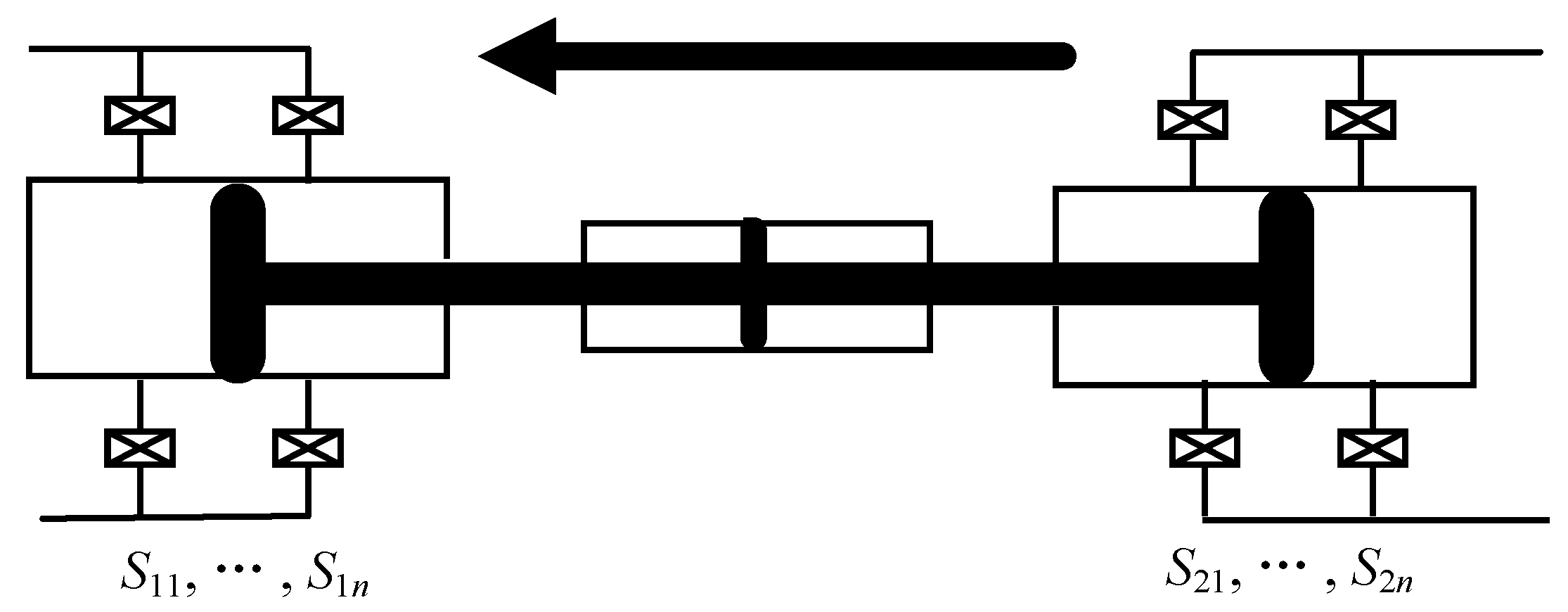
2.1. Principle of AHPET

An AHPET device is a controllable hydraulic device through which multiple groups of hydraulic potential energy sources can transfer energy among each other. Several coaxially connected hydraulic cylinders are further connected to different potential energy sources. The numbers and modes of hydraulic cylinders participating in the operation can be controlled by changing the on–off states of the valves of the hydraulic cylinders. Multistage hydraulic cylinders connected to the same potential energy sources have different effective cross-sectional areas. Therefore, the piston area ratio can be reasonably controlled according to the pressure changes on both sides of the potential energy sources; thus, hydraulic potential energy can be stably transferred among each group of potential energy sources, because the forces exerted on the piston rod, which are produced by the different hydraulic potential energy sources, cancel each other out in the process of piston movement. Total force bearing areas of multistage hydraulic pistons, on which the force produced by the same potential energy sources is exerted, are called “equivalent areas” under this force.
The equivalent areas of hydraulic cylinders are only discretely changed, and the change of air pressure is continuous. Therefore, a pressure difference will be produced when equivalent areas change. In order to ensure that the pressure difference exerted on the piston rod is still within the allowable range after equivalent areas change, extra energy compensation, such as changing longitudinal force exerted on the piston rod or changing the pressure and flow of liquid in a certain cylinder to achieve liquid flow control, is needed except for designing reasonable switching time so that stable operation of the hydraulic device can be achieved and potential energy transfer efficiency can be achieved.
An AHPET device is shown in Figure 1; it consists of two bidirectional hydraulic cylinder groups with coaxially connected piston rods; one is connected to potential energy source 1 and the other to potential energy source 2. P1 and P2 respectively denote the pressure difference of potential energy source 1 and potential energy source 2. S11, S12, ∙∙∙, S1m denote the effective cross-sectional areas of pistons in the hydraulic cylinders in the first hydraulic cylinder group, and S21, S22, ∙∙∙, S2n denote that of the second hydraulic cylinder group. m and n are the number of hydraulic cylinders in the first and second hydraulic cylinder groups, respectively. K1i and K2j respectively denote the operating state parameters of hydraulic cylinder i in the first hydraulic cylinder group and hydraulic cylinder j in the second hydraulic cylinder group, and the values of K1i and K2j are as follows:
K 1 i = { 1 0 1 , i = 1 , 2 , , m K 2 j = { 1 0 1 , j = 1 , 2 , , n
It is assumed that potential energy is transferred from potential energy source 2 to potential energy source 1; this implies that potential energy source 2 acts as a sender and potential energy source 1 is the receiver. In Equation (1), the values 0, 1, and −1 represent no force, negative force, and positive force exertion, respectively, on the pistons in the hydraulic cylinders of the potential energy sender and represent no force, positive force, and negative force exertion, respectively, for the potential energy receiver. Positive force means that the direction of force acting on the pistons is same as its motion direction, and negative force indicates that the direction of force exerted on the pistons is opposite to its motion direction.
To transfer maximum energy from potential energy source 2 to potential energy source 1 and improve the utilization efficiency of energy, the following principles should be followed when the equivalent area is chosen and extra force is compensated.
(1)
The equivalent area must be positive and should satisfy the following equation:
{ S 1 Σ = i = 1 m K 1 i S 1 i > 0 S 2 Σ = j = 1 n K 2 j S 2 j > 0 .
(2)
Work done by extra forces must help energy transfer rather than impede energy transfer—that is, force exerted on the piston rod must be positive. Output force Δ F should satisfy the following equation:
Δ F = P 1 i = 1 m K 1 i S 1 i P 2 j = 1 n K 2 j S 2 j > 0 .

2.2. Design and Area Optimization of Hydraulic Cylinders

Piston areas need to be rationally designed when the number of hydraulic cylinders connected to the same potential energy sources is more than one in each AHPET device; this makes the whole switching process more stable and the fluctuation of resultant force exerted on the piston rod minimal and easy to control. Taking two level hydraulic cylinders as an example, as shown in Figure 2, S1 and S2 represent the corresponding areas of two hydraulic cylinders. Different area ratios can be achieved if the on–off states of the valves are reasonably controlled when the piston rod moves to the right, as shown in Table 1. The on–off states of the valves are interchanged when the piston rod moves to the left.
Four kinds of equivalent areas, S1, S2S1, S2, and S1 + S2, can be achieved by an AHPET device with two level hydraulic cylinders. The overlap of equivalent areas should be avoided to use all equivalent areas effectively. In addition, the fluctuation of the resultant force exerted on the piston rod should be as small as possible to ensure the more stable operation of the hydraulic device when the equivalent area is changed. Therefore, the four kinds of equivalent areas produced by the abovementioned device should have uniform differences and should form an arithmetic progression as per the following equation:
( S 1 + S 2 ) S 2 = S 2 ( S 2 S 1 ) = ( S 2 S 1 ) S 1 .
This equation can be simplified as follows:
3 S 1 = S 2 .
Four equivalent areas, including 1, 2, 3, and 4, are generated when S1:S2 = 1:3, which is the best solution for a two-stage AHPET device. Similarly, the optimal piston areas ratio of the n-stage AHPET device is 1:3:9: ···:3n−1 and ( 3 n 1 ) / 2 equivalent areas can be obtained in this case.

3. Application to CAES

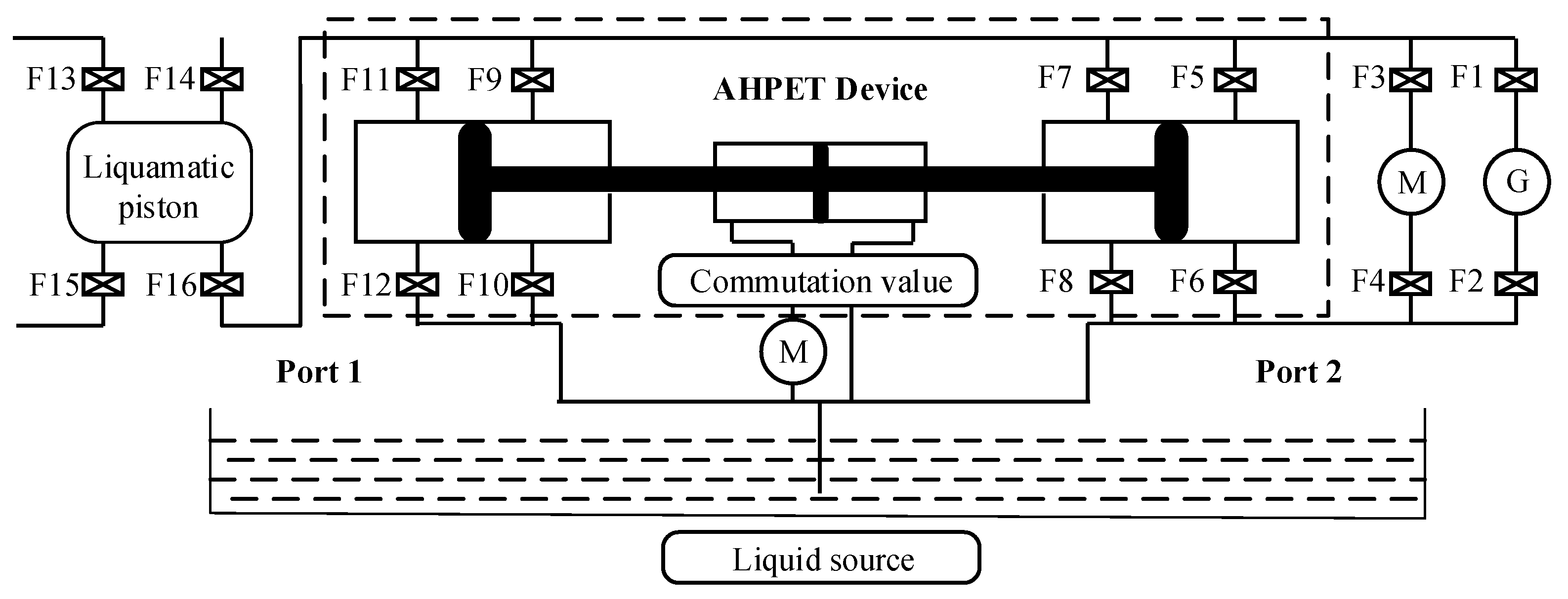
3.1. Structure of the System

A CAES system based on an AHPET device is shown in Figure 3, which includes the following: a liquamatic piston A1 (i.e., a liquid piston with internal temperature control), in which gas can be compressed or expanded by liquid and whose internal temperature can be maintained constant by liquid at the same time; an AHPET device; liquid sources; air storage chambers; and pumped storage unit. P1 and P2 denote constant liquid pressure at port 1 and port 2, respectively. Liquid source is a huge liquid pool, which is full of liquid with low pressure, which is used to compress air at port 1 and to generate electricity and is used by the hydraulic compensation system to produce extra force for the piston rod. The pump connected to the communication valves is a hydraulic pump, which can pump water into the hydraulic compensation system, and then, high pressure water can produce extra force on the piston rod. The maximum value of the energy change is determined by the volume and pressure resistance of the liquamatic piston A1 after the compression or expansion process happens once [21,22,23,24,25].
The AHPET device in the system is shown in Figure 4. Ports 1 and 2 are composed of a series of hydraulic cylinders with different effective cross-sectional areas of pistons, which can be expressed as S 11 , S 12 , , S 1 m and S 21 , S 22 , S 2 n , respectively. The piston area values are selected according to the principle in Section 2.2; therefore, ( 3 m + n 3 m 3 n + 1 ) / 4 equivalent areas are produced in the system. Some problems are faced when the values of m and n become large. Mechanical losses and space requirements increase, because the number of hydraulic cylinders becomes high, and piston areas become large; piston utilization ratio decreases because adjustable intervals are excessively overlapped, caused by too many equivalent areas. In this paper, two-stage hydraulic cylinders are designed in both first and second hydraulic cylinder groups, by which 16 equivalent areas are produced. Port 1 and port 2 are connected to liquamatic piston A1 and the pumped storage unit, respectively. Moreover, the pistons in the hydraulic cylinders at port 1 and port 2 are coaxially connected by a piston rod.

3.2. Strategies of Operation

Based on the principles mentioned in Section 2.1, a suitable equivalent area should be chosen and changed on both sides of the AHPET device to make the resultant force as small as possible, which will ensure that the AHPET device can have stable operations even if the pressure at port 1 is constantly changing, according to the pressure difference changes on both sides of the AHPET device. The resultant force is compensated by a single pump with a supplementation hydraulic cylinder.
Liquamatic piston A1 is filled with low-pressure air at the beginning of the energy storage process. Assuming that the piston rod in the AHPET device is moved to the left, valves F3, F4, F5, F8, F10, F11, and F16 are opened first. Pistons are pushed to move to the left by the liquid with fixed pressure from potential energy source 2, in which the pressure difference at port 2 is constant because an equal amount of liquid is pumped into the high-pressure end at port 2 by liquid pump M, which is powered by the residual electricity from the power grid, when liquid flows to the low-pressure end at port 2. In this process, electric energy is converted to hydraulic potential energy at port 2 and is then transferred to port 1; finally, it is converted into the potential energy of compressed air and is stored in liquamatic piston A1 temporarily. The equivalent area S 1 should be appropriately selected and changed because the pressure difference at port 1 increases gradually as the air is compressed, which causes the force exerted on the pistons in the first hydraulic cylinder group to increase gradually. In addition, the uniform motion of the piston rod is controlled by a single liquid pump with a supplementary hydraulic cylinder by providing proper output compensation to ensure the stable operation of the system. When the hydraulic piston moves to the leftmost end, valves F5, F8, F10, and F11 are closed, and valves F6, F7, F9, and F12 are opened, The piston rod in the AHPET device is moved to the right. The compression process is not complete until air is compressed to the specified pressure value. Compressed air is eventually transferred to external air storage chambers by opening valve F13, and liquamatic piston A1 is filled with low-pressure air again to prepare for the next compression process.
Liquamatic piston A1 is filled with liquid at the beginning of the power generation process. Compressed air with a certain volume is transferred to liquamatic piston A1, and liquid with equal volume is transferred to external air storage chambers by opening valve F13. Valve F13 is closed after this process. Assuming that the piston rod in the AHPET device is moved to the left, valves F1, F2, F6, F7, F9, F12, and F16 are opened first. The high-pressure air is expanded in the liquamatic piston A1, and electricity is generated through turbine G driven by the liquid with fixed pressure at port 2. Similar to S 1 , the equivalent area S 2 should to be appropriately selected and changed to ensure that the hydraulic potential energy at port 1 is transferred to port 2 in a stable manner. The uniform motion of the piston rod is still controlled by a single liquid pump with a supplementary hydraulic cylinder by providing the proper output compensation to ensure the stable operation of the system. However, in this case, when the hydraulic piston moves to the leftmost end, valves F6, F7, F9, and F12 are closed, and valves F5, F8, F10, and F11 are opened. The piston rod in the AHPET device is moved to the right. The expansion process is not complete until the air is expanded to a specified pressure or the liquamatic piston A1 is filled with air. Finally, the liquamatic piston A1 is filled with liquid again to prepare for the next expansion process.

3.3. Mathematical Model of the System

During the energy storage process, the pressure of the air in the liquamatic piston A1 is as follows:
P gas ( t ) = P 0 V A 1 V A 1 Q A 1 ( t ) d t = P 0 V A 1 V A 1 S 1 Σ v ( t ) d t
where P0 and v(t) represent atmospheric pressure and velocity of the piston rod, respectively.
Similarly, the pressure of the air in the liquamatic piston A1 is as follows during the power generation process:
P gas ( t ) = P 0 V 0 V 0 + S 1 Σ v ( t ) d t
The resultant force exerted on the hydraulic pistons at port 1 can be expressed as follows:
F 1 ( t ) = [ P g a s ( t ) P 0 ] S 1 Σ
Similarly, the resultant force exerted on the hydraulic pistons at port 2 can be expressed as follows:
F 2 ( t ) = P 2 S 2 Σ
The equivalent area on both sides of the AHPET device can be expressed as follows:
{ S 1 Σ = i = 1 2 K 1 i S 1 i > 0 , K 1 i = 0 , 1 , 1 S 2 Σ = j = 1 2 K 2 j S 2 j > 0 , K 2 j = 0 , 1 , 1
Considering resistance f exerted on the hydraulic pistons when the piston rod moves, the output compensation provided by the supplementary hydraulic cylinder can be expressed as follows:
F ( t ) = { e n e r g y   s t o r a g e F 1 ( t ) F 2 ( t ) f p o w e r   g e n e r a t i o n F 2 ( t ) F 1 ( t ) f
P2 can fluctuate between Pa and Pb (Pa < Pb) in the actual operation process. The values of Pa and Pb do not exceed ±5% of the rated value. Thus, the force exerted on the hydraulic pistons at port 2 can be expressed as follows:
P a S 2 Σ F 2 ( t ) P b S 2 Σ
Therefore, Equation (11) can be rewritten as follows:
F ( t ) { e n e r g y   s t o r a g e ( [ P g a s ( t ) P 0 ] S 1 Σ P a S 2 Σ f , [ P g a s ( t ) P 0 ] S 1 Σ P b S 2 Σ f ) p o w e r   g e n e r a t i o n ( P a S 2 Σ [ P g a s ( t ) P 0 ] S 1 Σ f , P b S 2 Σ [ P g a s ( t ) P 0 ] S A 1 f )

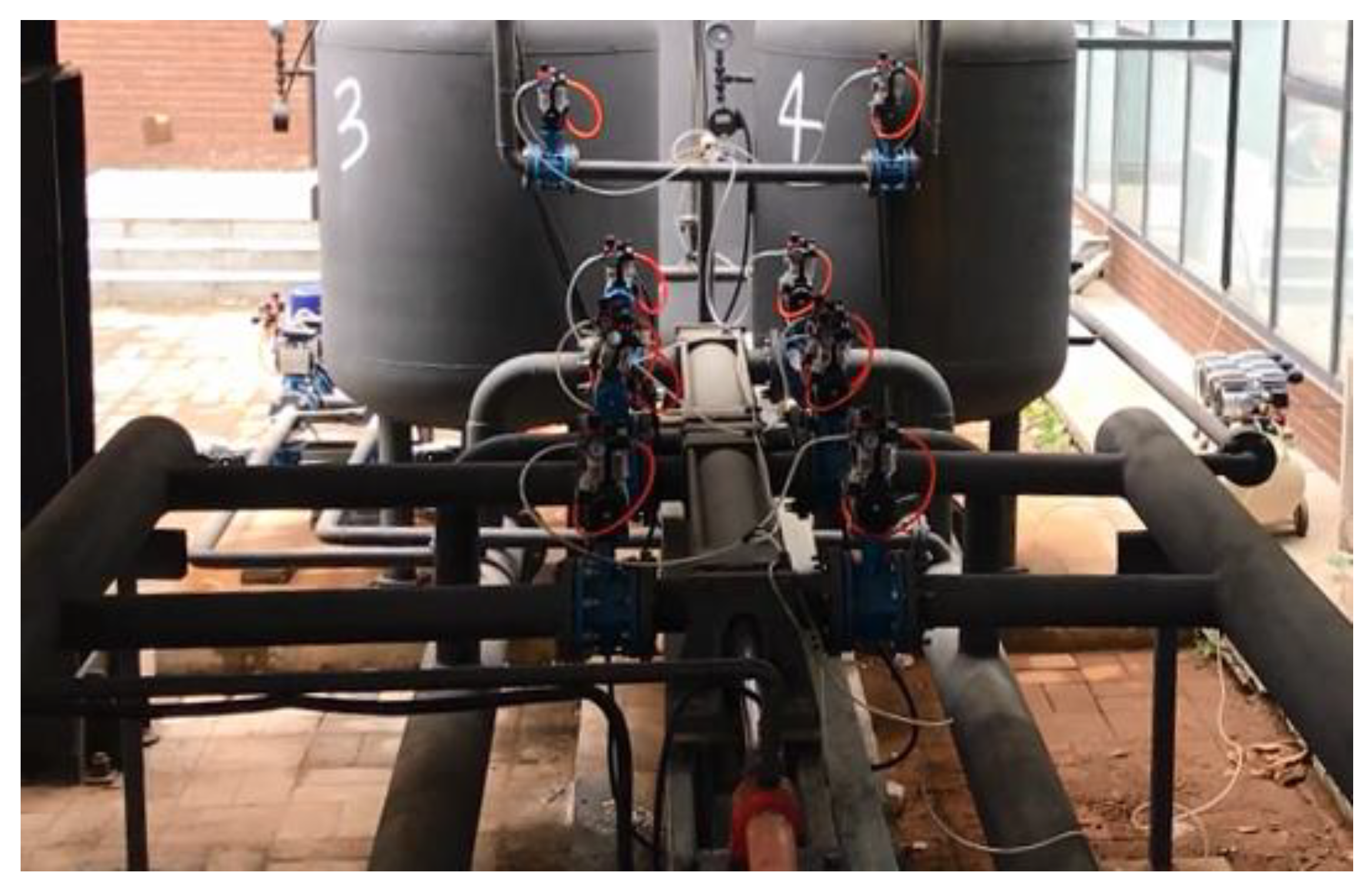
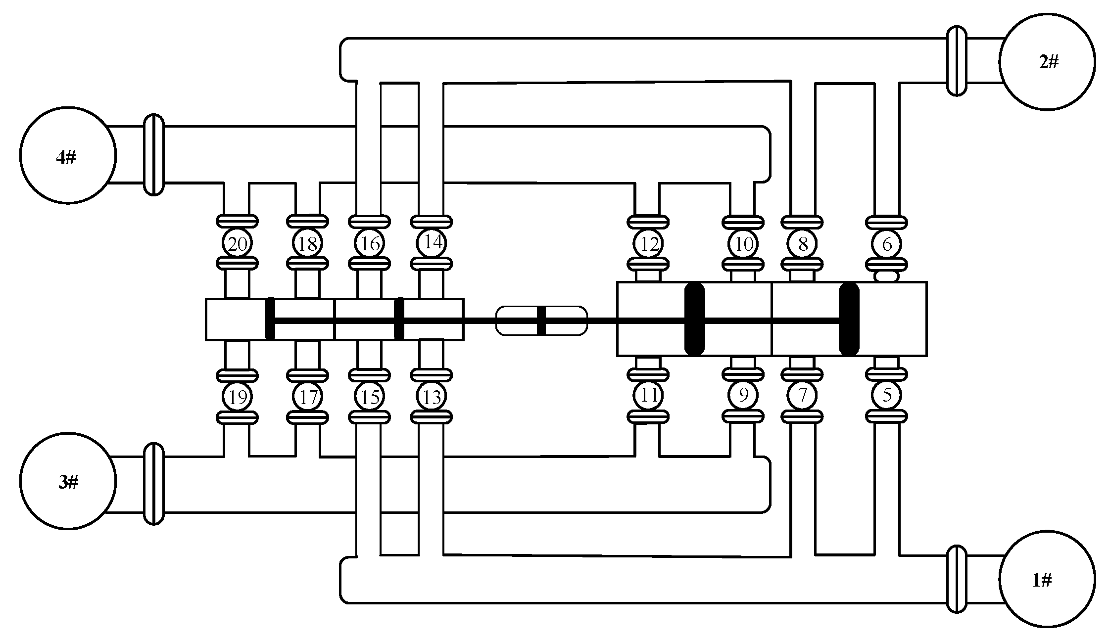
4. Physical Experiment

4.1. Design of Device

Based on the aforementioned principles and models, an adaptive hydraulic system, whose pressure rating is 1.6 MPa, was built as shown in Figure 5. The hydraulic potential-energy transfer subsystem was composed of an AHPET device and a hydraulic compensation system. The AHPET device consisted of two hydraulic cylinder groups. Two-stage hydraulic cylinders with S1:S2 ≈ 1:3 were designed in both the first and the second hydraulic cylinder groups, and all pistons were coaxially connected by a piston rod, where the types of the larger and smaller hydraulic cylinder were DN250 and DN150, respectively. One end of the AHPET device was respectively connected to high-pressure pool #1and low-pressure pool #1, and another was respectively connected to liquamatic piston #3 and liquamatic piston #4 through 16 pneumatic butterfly valves and four hydraulic pipes. Two liquamatic pistons, #3 and #4, had exactly the same structure and could operate alternately, as shown in Figure 6.
Pressure sensors were used to detect the pressure in the pressure vessels on both sides of the hydraulic system and to help to provide feedback results to a Programmable Logic Controller (PLC) system, which was used to send signals to control the on–off states of the valves and the output compensation provided by the hydraulic compensation system so that a suitable equivalent area could be selected and the piston rod could perform a uniform motion. Considering equipment safety and system stability, the switching of equivalent areas was carried out after the pistons moved to the terminal of the two ends, which could make the force exerted on the piston rod reach the maximum so that the AHPET device could stably operate in the range of working pressure. Thus, potential energy transfer efficiency was improved in the energy storage process, and the pressure difference between the high- and low-pressure pools was stabilized to maintain a constant water head interval for the high-efficiency generation of the turbine during the generation process.

4.2. Simulation of Operation

Based on the established 1.6-MPa LC-CAES experiment system, the processes of energy storage and generation were simulated according to the actual equipment parameters; so, an optimal operation scheme, which approximates the actual situation as much as possible, was designed. The continuous operation of the device consisted of multiple compression and expansion processes of air. The results of single compression and expansion processes of air are shown, because each compression and expansion process was the same. The parameters of the system are shown in Table 2.
Multiple equivalent-area selection schemes could be obtained according to the principle and initial parameters of the system. However, a reasonable selection of schemes should meet the following conditions to ensure the normal and highly efficient operation of the system: (1) The pressure intervals covered by the selected equivalent areas should overlap each other, but the overlapping parts should not be too large; (2) The operation time supported by the selected equivalent areas should be as long as possible and the equivalent areas should avoid being frequently changed so that the energy transfer is maximized when the equivalent areas are fixed, if the system has constant power. The data from the energy storage experiment and power generation experiment are given in Table 3 and Table 4, respectively.
The equivalent area ratio represents the ratio of the equivalent area on the variable pressure side to that on the constant pressure side. Table 3 shows that air can be compressed from 0.6 MPa to 1.45 MPa, and its volume correspondingly changes from 0.80 m3 to 0.36 m3 when three equivalent area ratios are chosen, and the compression ratio is 1.78 in the energy storage process. By contrast, it can be seen that air can be expanded from 1.45 MPa to 0.6 MPa and its volume correspondingly changes from 0.36 m3 to 0.8 m3 when three types of equivalent area ratios are chosen, and the expansion ratio is 1.78 in the power generation process from Table 4.
The pressure changes of the air in the liquamatic piston in both energy storage and power generation processes are shown in Figure 7. It can be seen that the air in the liquamatic piston can be compressed to over 1.4 MPa or expanded to 0.6 MPa continuously when three equivalent area ratios are chosen, and violent changes in the air pressure do not occur when the equivalent area ratio is changed in the operation of the system.
The pressure changes in the hydraulic compensation system in both the energy storage and power generation processes are shown in Figure 8. It can be seen that the air pressure increases as time goes on, when an equivalent area ratio is fixed. The equivalent area ratio is changed when the compensation pressure reaches its upper limit, which changes the pressure of the hydraulic compensation system back to the lower value so that it can be used again.
The output power of the hydraulic compensation system in both the energy storage and power generation processes are shown in Figure 9. It can be seen that the faster the piston rod moves, the higher the compensation pressure, which produces higher output power of the hydraulic compensation system.

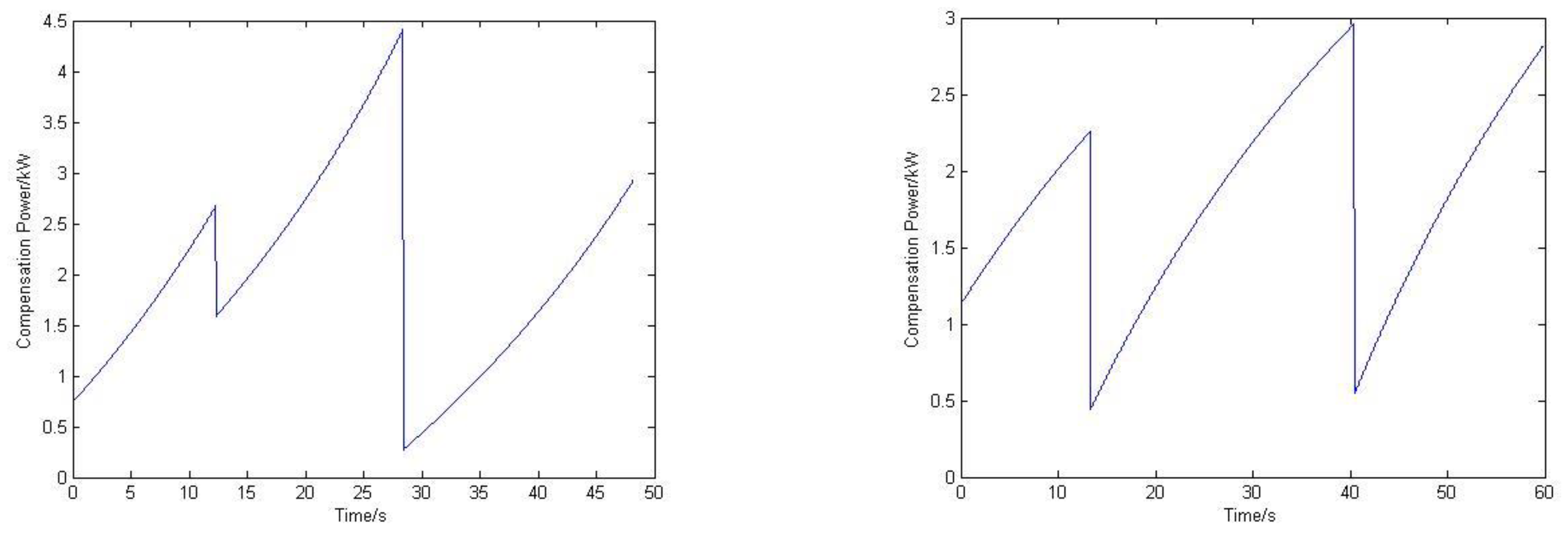
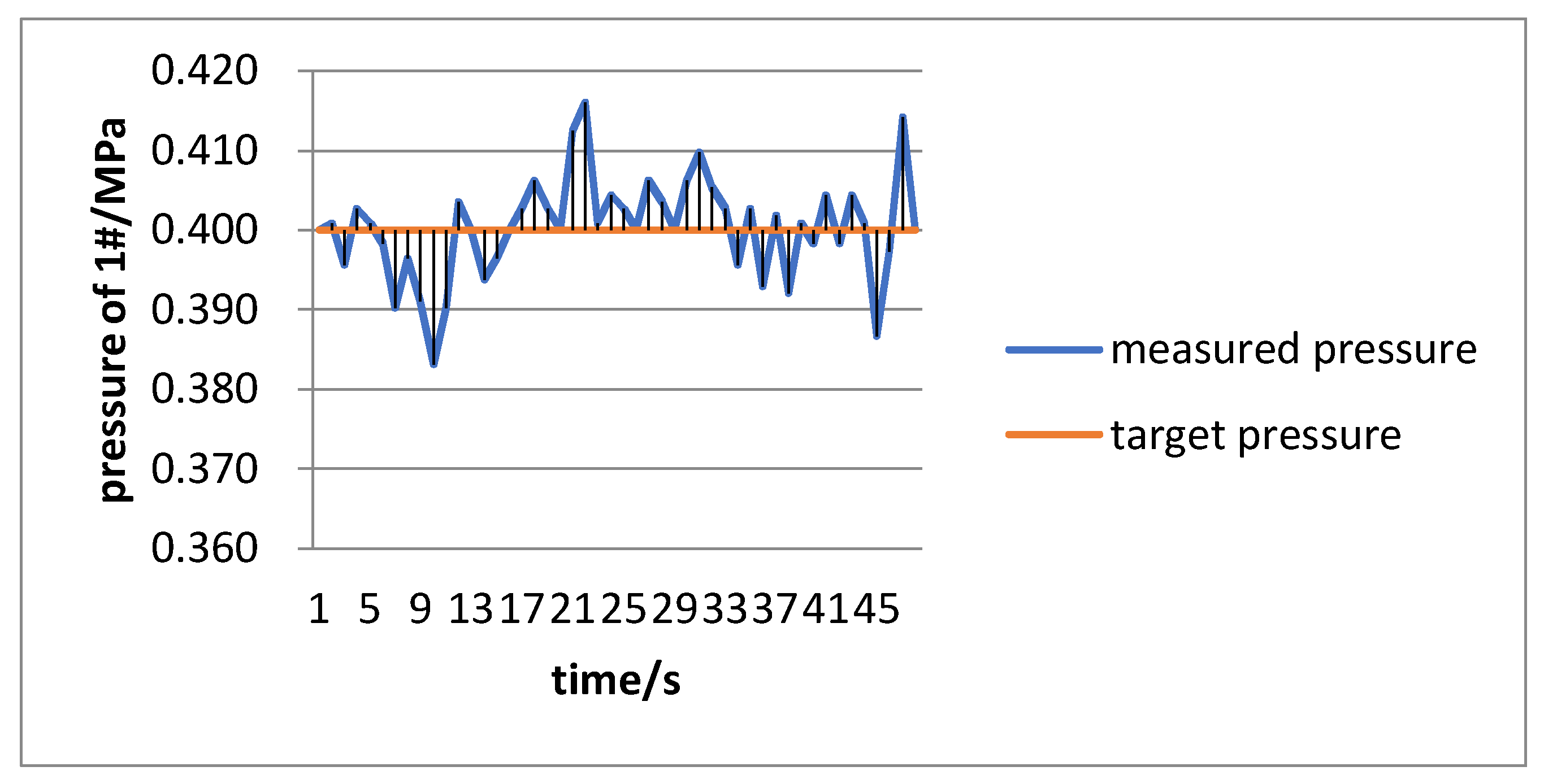
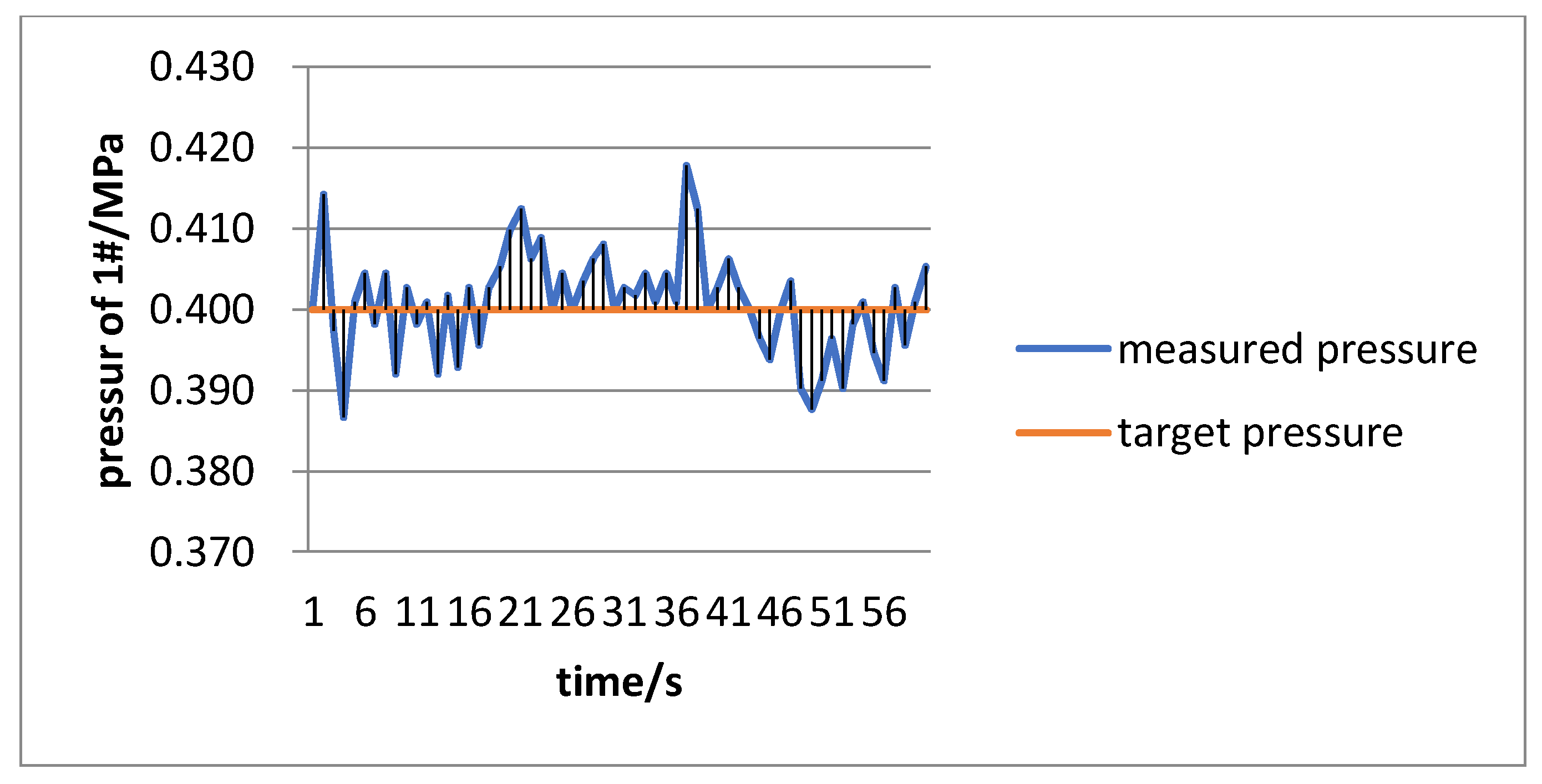
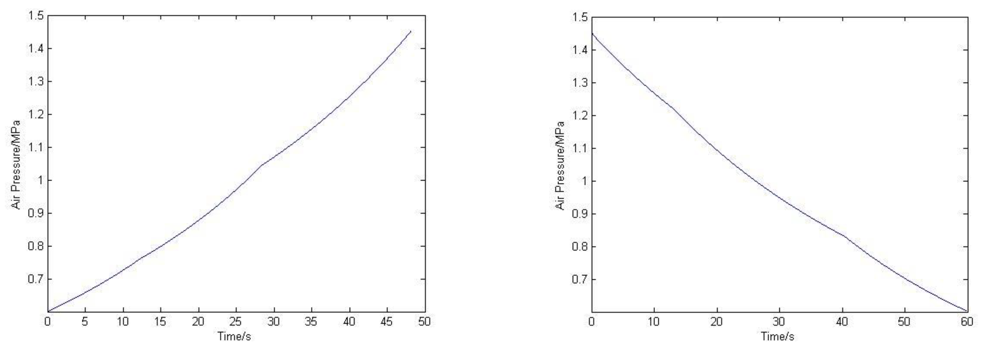
4.3. Results of the Experiment

According to the equivalent area ratios chosen in the simulation, the experiment was designed to verify whether the pressure of the high-pressure pool #1 can be maintained constant in both energy storage and power generation processes. The initial states of the system were preset according to Table 1. The output of the hydraulic compensation system was manually adjusted through a power amplifier plate and a voltage regulator so that the system could be corrected when large errors occurred during the actual operation. In the process of energy storage, the pressure changes in the high-pressure pool #1 in both the energy storage and power generation processes are shown in Figure 10 and Figure 11, respectively.
Figure 10 shows that the pressure in high-pressure pool #1 can be basically stable near 0.4 MPa, which corresponds to the rated water head of the water pump in the energy storage process. Specifically, the maximum pressure in high-pressure pool #1 was 0.418 MPa, which was 4.5% higher than 0.4 MPa, and the minimum pressure in high pressure pool #1 was 0.387 MPa, which was −3.25% higher than 0.4 MPa. The fluctuation of the pressure met the requirements of the system.
Figure 11 shows that the pressure in high-pressure pool #1 can be basically stable near 0.4 MPa, which corresponds to the rated water head of the water pump in the power generation process. Specifically, the maximum pressure in high-pressure pool #1 was 0.416 MPa, which was 4% higher than 0.4 MPa, and the minimum pressure of high pressure pool #1 was 0.383 MPa, which was −4.25% higher than 0.4 MPa. The fluctuation of pressure met the requirements of the system.
In summary, it has been proven that the design scheme described in Section 4.2 is feasible. At the same time, this shows that the fluctuant potential energy of the liquamatic piston can effectively be transferred into the essentially constant potential energy of high-pressure pool #1 by the AHPET device, which can be efficiently used.

5. Conclusions

The fluctuant potential energy can be transformed to relatively constant potential energy by the AHPET device, which makes the operation of connected equipment more stable and reduces control difficulty. In addition, constant water head pressure can guarantee long-time and high-efficiency operation of the water conservancy equipment, whose service life is further improved.
Mature hydraulic technology is used in the AHPET device to carry out hydraulic potential energy transfer. The optimal piston operation and output compensation schemes are designed according to the values of the hydraulic pressure on both sides of the AHPET device. The optimal equivalent area ratios are chosen through the on–off states of the valves by which directions of water flow can be changed so that fluctuant hydraulic potential energy can be transformed in real time to constant hydraulic potential energy, which can be efficiently used.
It is difficult to use the potential energy of compressed air in the HC-CAES system directly, and it reduces the operation efficiency of the equipment if it is directly used, because air pressure changes sharply with the change in air volume. The AHPET device helps to improve the quality of output potential energy of compressed air effectively, so the operating efficiency of the CAES system is greatly improved, because water conservancy equipment can efficiently operate in constant water head intervals, which aids in the development of CAES technology.
In summary, the AHPET device has outstanding performance in some respects, such as improving the efficiency of the CAES system, reducing the difficulty of system operation control, and prolonging the service life of equipment. Therefore, it is worth being promoted in energy storage and other technical fields in the future.

Author Contributions

H.F. conceived the main idea and wrote the manuscript with guidance from T.J., Y.C. and B.L., who reviewed the work and gave helpful improvement suggestions.

Funding

This work was supported by the Science and Technology Project of the State Grid Corporation of China (no. SGHE0000KXJS1700086) and the Fundamental Research Funds for the Central Universities (no. 2018QN004).

Acknowledgments

The authors thank the anonymous reviewers for careful reading and many helpful suggestions to improve the presentation of this paper. The authors thanks the anonymous referees for careful reading and many helpful suggestions to improve the presentation of this paper.

Conflicts of Interest

The authors declare no conflict of interest.

References

  1. Energy Information Administration. International Energy Outlook, 2010; Government Printing Office: Washington, DC, USA, 2010.
  2. Wang, H.; Wang, L.; Wang, X.; Yao, E.A. Novel Pumped Hydro Combined with Compressed Air Energy Storage System. Energies 2013, 6, 1554–1567. [Google Scholar] [CrossRef]
  3. De Bosio, F.; Verda, V. Thermoeconomic analysis of a Compressed Air Energy Storage (CAES) system integrated with a wind power plant in the framework of the IPEX Market. Appl. Energy 2015, 152, 173–182. [Google Scholar] [CrossRef]
  4. Daneshi, A.; Sadrmomtazi, N.; Daneshi, H.; Khederzadeh, M. Wind power integrated with compressed air energy storage. In Proceedings of the 2010 IEEE International Conference on Power and Energy (PECon), Kuala Lumpur, Malaysia, 29 November–1 December 2010; pp. 634–639. [Google Scholar]
  5. Wang, J.; Lu, K.; Ma, L.; Wang, J.; Dooner, M.; Miao, S.; Li, J.; Wang, D. Overview of Compressed Air Energy Storage and Technology Development. Energies 2017, 10, 991. [Google Scholar] [CrossRef]
  6. Mei, S.; Gong, M.; Qin, G.; Tian, F.; Xue, X.; Li, R. An advanced adiabatic compressed air energy system based on salt cavern air storage and its application prospects. Power Syst. Technol. 2017, 41, 3392–3399. [Google Scholar]
  7. Cavallo, A.J. Energy storage technologies for utility scale intermittent renewable energy systems. J. Sol. Energy Eng. 2001, 123, 387–389. [Google Scholar] [CrossRef]
  8. Linden, S.V. Bulk energy storage potential in the USA, current developments and future prospects. Energy 2006, 31, 3446–3457. [Google Scholar] [CrossRef]
  9. Rogers, A.; Henderson, A.; Wang, X.; Negnevitsky, M. Compressed air energy storage: Thermodynamic and economic review. In Proceedings of the PES General Meeting | Conference & Exposition IEEE, National Harbor, MD, USA, 27–31 July 2014; pp. 1–5. [Google Scholar]
  10. Chen, H.; Cong, T.N.; Yang, W.; Tan, C.; Li, Y.; Ding, Y. Progress in electrical energy storage system: A critical review. Prog. Nat. Sci. 2009, 19, 291–321. [Google Scholar] [CrossRef]
  11. Cheng, S.; Li, G.; Sun, H.; Wen, J. Application and prospect of energy storage in electrical engineering. Power Syst. Clean Energy 2009, 25, 1–8. [Google Scholar]
  12. Zhang, Y.; Yang, K.; Li, X.; Xu, J. A combined cooling, heating and power (CCHP) system based on advanced adiabatic compressed air energy storage (AA-CAES). J. Eng. Thermophys. 2013, 34, 1991–1996. [Google Scholar]
  13. Yang, K.; Zhang, Y.; Li, X.; Xu, J. Design and calculation of advanced adiabatic compressed air energy storage systems. J. Eng. Thermophys. 2012, 33, 725–728. [Google Scholar]
  14. Zhang, Y. Study on System Integration and Simulation of Wind Power and Advanced Adiabatic Compressed Air Energy Storage Technology. Ph.D. Thesis, Institute of Engineering Thermophysics, Chinese Academy of Sciences, Beijing, China, 2014. [Google Scholar]
  15. Guo, H.; Xu, J.; Chen, H.; Tan, C. System efficiency analysis of a constant-pressure AA-CAES. J. Eng. Therm. Energy Power 2013, 28, 540–546. [Google Scholar]
  16. Li, X.; Yang, K.; Zhang, Y. Operation level optimization of compression and expansion systems in advanced adiabatic compressed air energy storage systems. J. Eng. Thermophys. 2013, 34, 1649–1653. [Google Scholar]
  17. Xue, X.; Mei, S.; Lin, Q.; Chen, L.; Chen, Y. A preliminary study on energy internet-oriented non-after-burning compressed air energy storage and its application prospects. Power Syst. Technol. 2016, 40, 164–171. [Google Scholar]
  18. Ho, T.H.; Ahn, K.K. Modeling and simulation of hydrostatic transmission system with energy regeneration using hydraulic accumulator. J. Mech. Sci. Technol. 2010, 24, 1163–1175. [Google Scholar] [CrossRef]
  19. Payne, G.S.; Kiprakis, A.E.; Ehsan, M.; Rampen, W.H.S.; Chick, J.P.; Wallace, A.R. Efficiency and dynamic performance of Digital Displacement™ hydraulic transmission in tidal current energy converters. Proceedings of the Institution of Mechanical Engineers, Part A. J. Power Energy 2007, 221, 207–218. [Google Scholar] [CrossRef]
  20. Dickinson, B.W.O., III; Dickinson, R.W.; Hutchison, S.O. Hydraulic Piston-Effect Method and Apparatus for Forming a Bore Hole. U.S. Patent US4527639, 9 July 1985. [Google Scholar]
  21. Bi, J.; Jiang, T.; Chen, W.; Ma, X. Research on storage capacity of compressed air pumped hydro energy storage equipment. Energy Power Eng. 2013, 5, 26–30. [Google Scholar] [CrossRef]
  22. Muller, S. General compression moves ahead with unique energy storage technology. Power Daily 2010, 8, 1. [Google Scholar]
  23. Duan, X.; Li, S.; Wu, Y.; Li, L. Application of advanced adiabatic compressed air energy storage in microgrids. Electr. Power Sci. Eng. 2015, 31, 48–54. [Google Scholar]
  24. Fu, H.; Zhang, Y.; Cui, Y.; Zhang, L.; Jiang, T. Research development of compressed air energy storage systems. Sci. Technol. Rev. 2016, 34, 81–87. [Google Scholar]
  25. Ekman, C.K.; Jensen, S.H. Prospects for large scale electricity storage in Denmark. Energy Conv. Manag. 2010, 51, 1140–1147. [Google Scholar] [CrossRef]
Figure 1. Principle of adaptive hydraulic potential energy transfer.
Energies 11 01845 g001
Figure 2. Principle of grading pressure increase on hydraulic cylinders.
Energies 11 01845 g002
Figure 3. Principle of a compressed air energy storage (CAES) system based on an adaptive hydraulic potential energy transfer (AHPET) device.
Energies 11 01845 g003
Figure 4. Design of hydraulic pistons in an AHPET device.
Energies 11 01845 g004
Figure 5. Physical platform of the hydraulic system.
Energies 11 01845 g005
Figure 6. Physical connection of the hydraulic mechanism.
Energies 11 01845 g006
Figure 7. Pressure changes of air in liquamatic piston.
Energies 11 01845 g007
Figure 8. Pressure changes in hydraulic compensation system.
Energies 11 01845 g008
Figure 9. Output power of the hydraulic compensation system.
Energies 11 01845 g009
Figure 10. Pressure changes in high pressure pool #1 in the energy storage process.
Energies 11 01845 g010
Figure 11. Pressure changes in high pressure pool #1 in the power generation process.
Energies 11 01845 g011
Table 1. Relationship between the equivalent area of the pistons and the on–off states of the corresponding valves.
Equivalent AreaOpen ValvesClosed Valves
S1F2, F3, F6,F8F1, F4, F5, F7
S2S1F1, F4, F6, F7F2, F3, F5, F8
S2F2, F4, F6, F7F1, F3, F5, F8
S1 + S2F2, F3, F6, F7F1, F4, F5, F8
Table 2. Initial parameters of the system (where friction is measured with a tension meter).
Volume of Air in Liquamatic Piston/m3Pressure of Air in Liquamatic Piston/MPaWater Head of High-Pressure Pool/MPaMaximum Compensation Pressure/MPaFriction/NConstant Power of Water Pump/kW
0.3–0.80.6–1.60.452272.627.5
Table 3. Data from the energy storage experiment.
Schemes of Equivalent AreaEquivalent Area on Variable Pressure SideEquivalent Area on Constant Pressure SidePressure of Air in Liquamatic Piston/MPaVolume of Air in Liquamatic Piston/m3Velocity of Piston Rod/m/sOperation Time/s
1230.60–0.760.80–0.650.4012.35
2120.76–1.040.65–0.490.6216.06
3131.04–1.450.49–0.360.4019.76
Table 4. Data from the power generation experiment.
Schemes of Equivalent AreaEquivalent Area on Variable Pressure SideEquivalent Area on Constant Pressure SidePressure of Air in Liquamatic Piston/MPaVolume of Air in Liquamatic Piston/m3Velocity of Piston Rod/m/sOperation Time/s
1141.45–1.220.36–0.430.4012.35
2131.22–0.830.43–0.600.6216.06
3120.83–0.60.60–0.800.4019.76

