Article

Large-Signal Stabilization of Three-Phase VSR with Constant Power Load

School of Electrical Engineering and Automation, Harbin Institute of Technology, Harbin 150001, China
*
Author to whom correspondence should be addressed.
Energies 2018, 11(7), 1706; https://doi.org/10.3390/en11071706
Submission received: 18 May 2018 / Revised: 19 June 2018 / Accepted: 27 June 2018 / Published: 1 July 2018
(This article belongs to the Special Issue Power Electronics in DC-Microgrid Systems)

Abstract

:
As an important interface converter, the three-phase voltage-source rectifier (VSR) connects the grid to DC-input converters. The constant power load (CPL) characteristic of the converter-load often causes large-signal stability problems. In order to solve this problem, the stability boundary of the VSR with CPL is analyzed based on the mixed potential theory, and the stability condition under large-signal disturbance is obtained; thus, the jump range of the load power can be estimated. To improve the stability of the system, a voltage loop control scheme based on ADRC is proposed. A theoretical analysis based on the mixed potential theory shows the proposed scheme expands the power jump range of the VSR with CPL effectively, and improves its disturbance rejection performance. Finally, experimental results prove the effectiveness of the proposed control scheme.

1. Introduction

In order to achieve the goal of multi-functionality, low-cost and high reliability, modularization has become an important trend in power electronics [1,2,3]. In the process of modularizing power electronic devices, the situation of converters as loads becomes more and more common, and has attracted wide attention [4,5]. As important interface converters, three-phase voltage-source rectifiers (VSRs) connect the grid to DC-input converters, and are widely used in the fields of electric vehicle charging [6], DC micro-grid [7], more electric aircrafts (MEAs) [8], and photovoltaic generation [9].
Many academic papers have focused on stability issues related to three-phase VSRs (or voltage-source inverters, VSIs). In [10], bifurcation and large-signal stability of VSR are analyzed under grid voltage dips, and the stable operating region is identified. Mehrasa M. and Pouresmaeil E. use direct Lyapunov method to discuss a series of stability issues of VSRs applied in different power sectors such as modular multilevel converters (MMCs) [3,11], shunt active power filters [12], and distributed generation [13,14]. A dynamic model in d-q frame with six independent dynamical state variables is obtained, and global asymptotical stability is achieved by the use of direct Lyapunov method [11]. Furthermore, a multi-loop control strategy is proposed to provide stable operation under both MMC’s arm inductance and resistance parameters variations, and also loads changes [3].
However, the above studies do not focus on the effect of load characteristics on the stability of VSR. Figure 1 shows the schematic of a three-phase VSR cascaded with a DC-input converter. In this situation, for VSR, the load is no longer a resistance, but a converter with a constant power load (CPL) characteristic because of its closed-loop control. The CPL causes stability problems easily [15,16,17]; moreover, the problems are more significant when the DC-bus capacitance is a small-capacity film capacitor to improve the system life and reliability. Some scholars have discussed this problem and put forward some solutions based on small signal stability theory, such as the passive damping method [18,19], sliding mode control method [17], virtual impedance (active damping) method [20,21,22], and so on. However, when the cascaded system suffers from a large-signal disturbance such as load power jump or grid voltage drop, the small signal stability theory is no longer applicable, because the theory only studies the stability problems near the operating point.
The problems of large-signal stability in converters with CPLs were analyzed in some literature in recent years [16,23,24]. In [23], the large-signal stability region of a DC/DC converter is estimated by a small signal loop. The norm inequalities are used to get the sufficient conditions for converter stability in order to estimate the stable region of the system. Furthermore, the effect of the small signal loop gain on the large-signal stability region is revealed. In [24], the Hamiltonian function method is used to discuss the influence of pulse load on the stability of the system, and some details of the transient response are shown. It indicates that pulse load has special effect on the stability of cascaded systems. For example, the system is in an unstable state when the load is connected, however it may attenuate to a stable state during the load disconnection. In general, it was called a metastable state. In [16], the influence of the negative impedance characteristic of CPLs on the stability of the converter is studied based on the mixed potential theory. In addition, a method to improve the large-signal stability in the cascade system is proposed with multistage LC filters. However, this method requires additional passive components, which increases the volume of the device.
On the premise of no additional circuits, some meaningful work on control methods has been undertaken to improve the large-signal stability of converters with CPLs [25,26,27,28]. The sliding mode control method to improve the stability of VSR is proposed in [25]. In this method, the voltage loop is controlled by sliding mode, and the state observer of the real-time power of the system is designed to observe the power. Furthermore, the parameters of the state observer are derived from the Lyapunov stability theorem. However, for different systems, there is no uniform method to establish the Lyapunov function, so the realization process of the control algorithm is relatively complicated. Moreover, due to the boundary of the current and grid voltage, the range of attraction area for large-signal disturbance is limited, which limits its practicality. In [26], a “stabilizing agent” is implemented on each CPL to reduce the negative impedance characteristic to solve the DC micro-grid stability problem. Thanks to the improved fault tolerance of the solution, the method permits us to consider several fault scenarios, such as the electrical reconfiguration, or the failure of an agent. In [27], multiple linear controllers are designed at different operating points of a three-phase VSR and switched according to certain rules. When the load changes, the drop and overshoot of DC bus voltage are both significantly reduced. The stability of the control method is proved by the general Lyapunov functions. To improve the dynamic performance of three-phase VSR with large-signal disturbance, a direct voltage control method based on feedback linearization is proposed in [28]. The scheme breaks through the conventional double closed-loops control mode, and directly controls input variables by voltage error, so as to stabilize the bus voltage rapidly. However, this scheme relies on an accurate mathematical model of the circuits. Some abnormal operating conditions, such as the imbalance of the grid voltage, would lead to poor control performance.
Active disturbance rejection control (ADRC) has been widely studied because of its excellent immunity against disturbance sources [29,30,31], and has been applied to motion control [30], power electronics, and so on [31]. However, the stability of converters with ADRC has not been adequately analyzed, especially for large-signal stability problems.
In this paper, the authors are discussing the large-signal stability of three-phase VSRs with CPL. The main contributions are triple:
(1)
Obtaining a large-signal model of three-phase VSR with CPL based on mixed potential theory, whose stable boundary is derived when load power jumps.
(2)
Proposing a voltage control scheme to improve the large-signal stability based on ADRC, and whose control stability is proven.
(3)
Deriving the stable boundary of VSR with CPL based on ADRC, which proves that the proposed control scheme expands the load power jump range effectively.
The rest of this paper is organized into four sections. Following the introduction, a large-signal stability analysis based on mixed potential theory under PI control is provided in Section 2. The proposed control scheme based on ADRC and the stability analysis of it is presented in Section 3. Moreover, the effectiveness of the control scheme is verified by experiments in Section 4. Finally, some conclusions are drawn in Section 5, and an Appendix A is given after that.

2. Large-Signal Stability Analysis Based on Mixed Potential Theory under PI Control

2.1. Introduction to the Mixed Potential Theory

The mixed potential theory is a method to study the stability of nonlinear circuits by constructing Lyapunov functions, especially for circuits with CPLs [32,33]. The mixed potential functions are functions related to energy, which are composed of current potential functions and voltage potential functions. The core content of the theory is to establish mixed potential functions to satisfy certain stability theorems, and finally, to obtain the ranges of the system parameters to ensure stability.
The mixed potential function P consists of resistance, capacitance, and inductance in a nonlinear network. Assume i1, …, ir represents inductor currents, and vr+1, …, vr+s are capacitor voltages. P is defined as:
P = μ > r + s v μ d i μ + σ = r + 1 r + s i σ v σ
In Equation (1), the first item on the right is the current potential of all the non-storage elements; the second is the sum of energy in capacitors. If vμ can not be represented by iμ, the current potential can be written by voltage potential and Equation (2):
v μ d i μ = v μ i μ i μ d v μ
The relationship between P and the system state equation can be described as:
{ L d i ρ d t = P i ρ C d v σ d t = P v σ
where L and C are inductance and capacitance respectively in the circuit.
Equation (3) gives the criterion to verify the validity of the mixed potential functions. Generally speaking, the unified form of P is:
P ( i , v ) = A ( i ) + B ( v ) + ( i , γ v α )
where A(i) and B(v) represents the current potential and voltage potential of the non-storage elements in the circuit respectively, (i, γvα) represents the energy of capacitors and parts of non-storage elements in the circuits, where γ is a constant matrix not necessarily associated with circuit topology with elements ±1, 0, and α is constant vector.

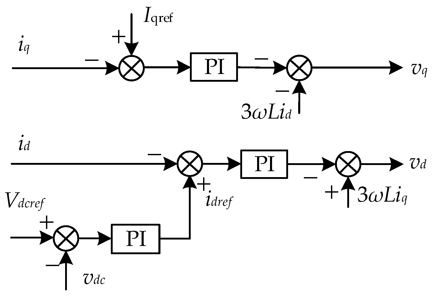
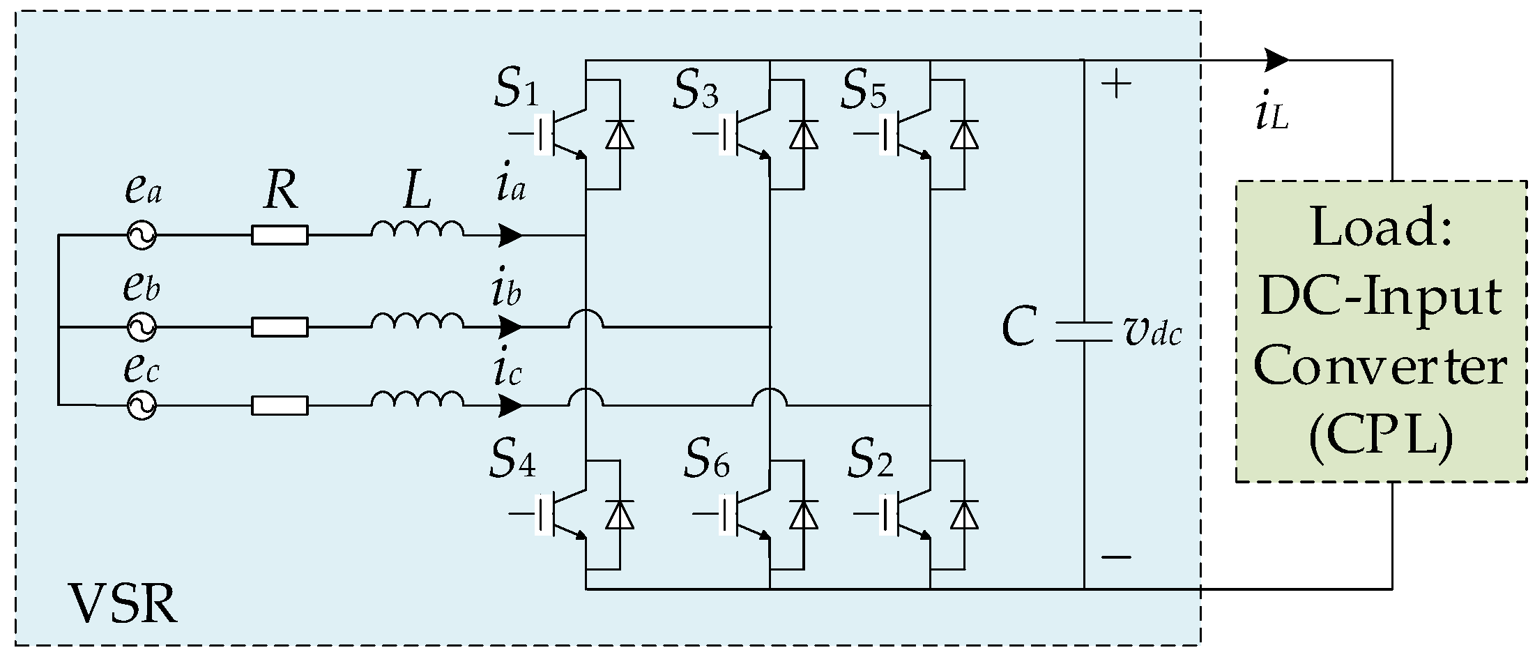
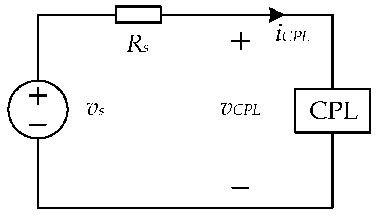
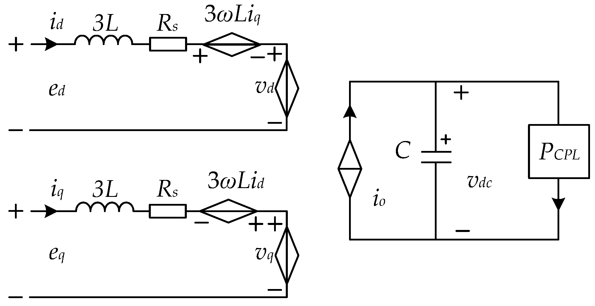
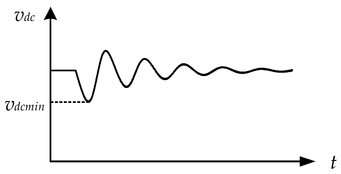
2.2. Stability Problems of the Three-Phase VSR with CPL

Because VSRs are often used as grid interface converters, their loads are usually not resistors, but power electronic converters. Power electronic converters are usually controlled by closed loops; therefore, they are regarded as CPLs. Taking the DC/DC converter as an example of the load, when the input current suddenly rises, the input voltage will decrease in order to maintain the output constant. The characteristic of maintaining constant power is called the CPL characteristic. This characteristic is bad for the stability, which will be explained below.
Take the voltage source in series with CPL as an example, as shown in Figure 2. When the CPL is disturbed to cause the input current iCPL to rise, in order to maintain its output constant, the input voltage vCPL of the CPL will decrease. However, this will lead to an increase in the voltage on the resistance Rs to make the current iCPL rise again. This response, similar to positive feedback, takes the circuit away from the operating point, and causes it to lose stability. The larger the disturbance, the more significant stability problems caused by CPL will be.

2.3. Analysis of Power Jump Range of Three-Phase VSR with CPL

The average model equivalent circuit of three-phase VSR with CPL in dq coordinates system is shown in Figure 3. Neglecting the power loss, Equation (5) can be obtained based on the power balance.
i o = v d i d + v q i q v d c
where vd,q are the control voltage in the dq coordinates respectively, id,q are the grid current in the dq coordinates respectively, io is the output current of the equivalent current source on the DC side, and vdc is the output voltage of the VSR.
According to the mixed potential theory, the current potential function of non-storage elements in the circuit is:
μ > r + s v μ d i μ = 0 i d e d d i d 0 i d R i d d i d 0 i d v d d i d + 0 i d 3 ω L i q d i d + 0 i q e q d i q 0 i q R i q d i q 0 i q v q d i q 0 i q 3 ω L i d d i q + 0 i o v d c d i o 0 i L v d c d i L
where vd,q are the control voltage in the dq coordinates respectively, R is the equivalent series resistance of the grid side, iL is the load current of the VSR.
The potential energy stored in the capacitor in the circuit is:
δ = r = 1 r + s i δ v δ = i o v d c + P C P L
where PCPL is the power of the CPL.
From Equations (6) and (7), the mixed potential function of the system can be obtained as:
P ( v , i ) = μ > r + s v μ d i μ + δ = r = 1 r + s i δ v δ = e d i d + e q i q 1 2 R i d 2 1 2 R i q 2 0 i d v d d i d 0 i q v q d i q + 0 i d 3 ω L i q d i d 0 i q 3 ω L i d d i q 0 v d c i o d v d c + 0 v d c P C P L v d c d v d c
According to Equation (3), the relationship between P and the state equations of the circuit can be used to verify the correctness of the function:
{ P i d = e d R i d v d + 3 ω L i q = L d i d d t P i q = e q R i q v q 3 ω L i d = L d i q d t P v d c = i o + P c p l v d c = C d v d c d t
This indicates that Equation (9) satisfies the form Equation (3), which proves that the mixed potential function P is correct.
The proportional integral (PI) regulators are commonly used to control voltage and current of the three-phase VSR, as shown in Figure 4. The control loop equations are:
{ ( 10 a ) v d = ( K i p ( i d r e f i d ) + K i i ( i d r e f i d ) d t ) + 3 ω L i q ( 10 b ) v q = ( K i p ( I q r e f i q ) + K i i ( I q r e f i q ) d t ) 3 ω L i d ( 10 c ) i d r e f = K v p ( V d c r e f v d c ) + K v i ( V d c r e f v d c ) d t
where Vdcref is the output voltage reference of the VSR, Iqref is the current reference of the q axis, ω is the frequency of the grid, Kip and Kii are the proportion and integral coefficients of PI regulator of d axis current and q axis current respectively, Kvp, Kvi are the proportion and integral coefficients of PI regulator in voltage loop, respectively.
According to Appendix A, the current potential function of the circuit is a second order matrix:
A ( i ) = [ e d i d + 1 2 R i d 2 + 0 i d v d d i d + 0 i d 3 ω L i q d i d 0 0 e q i q + 1 2 R i q 2 + 0 i q v q d i q 0 i q 3 ω L i d d i q ]
and the voltage potential function is a first order matrix:
B ( v ) = 0 v d c i o d v d c + 0 v d c P C P L v d c d v d c
In order to analyze the stability, the second order partial derivatives of A(i) and B(v) are solved as:
A i i _ P I ( i ) = 2 A ( i ) i 2 = [ R + K i p 0 0 R + K i p ]
B v v _ P I ( v ) = 2 B ( v ) v 2 = K v i K i p i d C ( V d c r e f v d c ) e d i d P C P L K v p K i p i d v d c + v d i d P C P L v d c 2
According to the mixed potential stability theorem in the Appendix A, the sufficient condition for the stability of the three-phase VSR with CPL under large-signal perturbation is:
P C P L _ P I < C ( R + K i p ) 3 L v d c 2 K v p K i p v d c i d + v d i d + K v i K i p C v d c e d i d P C P L _ P I ( V d c r e f v d c ) M
By Equation (15), the maximum power jump range of the three-phase VSR with CPL can be estimated. This result is used on the one hand to measure the performance of the VSR, and on the other hand, as a technical requirement to improve the parameter design. It is worth noting that because this result is a sufficient condition for large-signal stability, it is somewhat conservative.

3. Control Scheme and Stability Analysis Based on ADRC

In the case of disturbance, the principle of PI regulators is to compensate for errors which occur in the integrator. However, when the disturbance is large, the delay effect of the integrator makes the regulator unable to quickly and accurately obtain the disturbance information and compensate, which easily leads to instability. Therefore, a control scheme based on ADRC with excellent immunity is proposed to enhance the stability of VSR with CPL under large-signal disturbance.
The general structure of ADRC is shown in Figure 5. It includes the expanded state observer (ESO), the state error feedback (SEF), the transient profile generation (TPG) and the rejection. ADRC is not dependent on the mathematical model of the controlled plant. All the uncertain disturbances acting on the controlled plant are considered as “uncertain disturbances”, and the input and output signals are used to estimate and compensate for them. Thanks to the ESO and rejection, ADRC has omitted the integral part compared with the conventional PI regulator. This characteristic coincided with the need to improve the stability under large-signal disturbance. In this paper, a linear ADRC is proposed and the parameters can be simplified by ESO bandwidth and system bandwidth, which makes it easy to set.

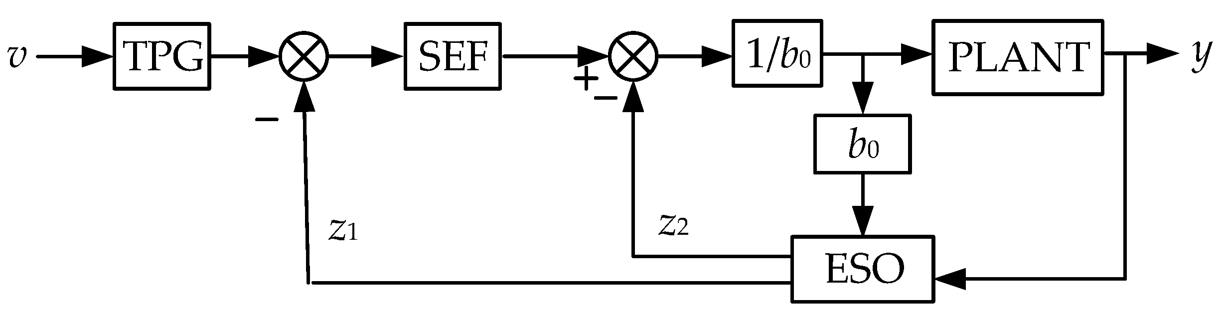
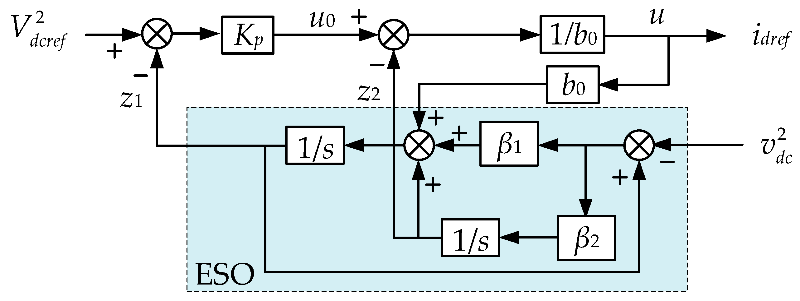
3.1. Voltage Loop Control Scheme Based on the First Order ADRC

The control block of the voltage loop of three-phase VSR based on ADRC is shown in Figure 6. For the three-phase VSR with CPL, the DC side voltage equation is:
C d v d c d t = e d i d R i d 2 v d c P C P L v d c
Ignoring the equivalent series resistance R and matching the form of ADRC plant, Equation (16) is rewritten as a first order differential equation:
y ˙ = w + b u
where w = 2 P C P L / C is the external disturbance, u = i d r e f is the reference of d-axis current, b = 2 e d / C is the control gain, and y = v d c 2 is the input of ADRC.
Assume b 0 b is the estimation of control gain. Let x 1 = y , uncertain disturbance (including external disturbance and internal disturbance) f ( y , y ˙ , u ) = w + ( b b 0 ) u . Then, extending the uncertain disturbance to the state variable x 2 = f ( y , y ˙ , u ) , the state equations of voltage loop are:
{ x ˙ 1 = x 2 + b 0 u x ˙ 2 = h y = x 1
where x1, x2 is the state variables, and h = f ˙ ( y , y ˙ , u ) .
A liner ESO can be established from Equation (18) as:
{ z ˙ 1 = z 2 + β 1 ( x 1 z 1 ) + b 0 u z ˙ 2 = β 2 ( x 1 z 1 )
Suitable gains β1 and β2 make z1 and z2 in ESO achieve good tracking effect on x1 and x2. Ignore the estimation error of ESO, that is, z 1 x 1 and z 2 x 2 . Meanwhile, if we let
u = z 2 + u 0 b 0
Equation (17) can be simplified as:
y ˙ = ( f ( y , y ˙ , u ) z 2 ) + b 0 u = u 0
The SEF of ADRC is designed as a proportional term:
u 0 = K p ( v z 1 )
where v = V d c r e f 2 .

3.2. Parameters Simplification and Stability Proof

First, the key parameters of ESO and SEF in ADRC are designed. For the ESO as Equation (19), the characteristic polynomial is given by:
λ ( s ) = s 2 + β 1 s + β 2
Setting the pole of the characteristic equation as ESO bandwidth ω 0 , which results in:
β 1 = 2 ω 0 ,   β 2 = ω 0 2
Let the proportional gain
K p = ω c
where ω c is the system bandwidth.
Therefore, the parameters design of the ADRC is simplified as the design of system bandwidth and ESO bandwidth. In this paper, taking ωc = 100. According to engineering experience, ω0 is generally five to ten times ωc, and is set as ω0 = 800 here.
In order to prove the VSR based on ADRC stable, the convergence of ESO should be proven first. From Equations (19) and (24), the transfer functions of the variables z1 and z2 of ESO in the frequency domain are given by:
z 1 = β 1 s + β 2 s 2 + β 1 s + β 2 y + b 0 s s 2 + β 1 s + β 2 u = 2 ω 0 s + ω 0 2 s 2 + 2 ω 0 s + ω 0 2 y + b 0 s s 2 + 2 ω 0 s + ω 0 2 u
z 2 = β 2 s s 2 + β 1 s + β 2 y b 0 β 2 s 2 + β 1 s + β 2 u = ω 0 2 s s 2 + 2 ω 0 s + ω 0 2 y b 0 ω 0 2 s 2 + 2 ω 0 s + ω 0 2 u
Let the tracking error e 1 = z 1 y and e 2 = z 2 f ( y , y ˙ , u ) , then
e 1 = s 2 s 2 + 2 ω 0 s + ω 0 2 s y + b 0 s s 2 + 2 ω 0 s + ω 0 2 s u
e 2 = ( 1 ω 0 2 s 2 + 2 ω 0 s + ω 0 2 ) y s + ( 1 ω 0 2 s 2 + 2 ω 0 s + ω 0 2 ) b 0 u
Without loss of generality, y and u are all set as step signals of magnitude K, that is, y = K/s and u = K/s. Then the steady-state errors are:
{ e 1 s = lim s 0   s e 1 = 0 e 2 s = lim s 0   s e 2 = 0
This indicates that the ESO has good convergence and estimation. On this basis and from Equations (17)–(22), the voltage closed loop transfer function of VSR based on ADRC is given by:
G ( s ) = K p s + K p
Obviously, if only Kp > 0, the three-phase VSR based on ADRC is stable.

3.3. Large Sigal Stability Analysis of Three-Phase VSR with CPL Based on ADRC
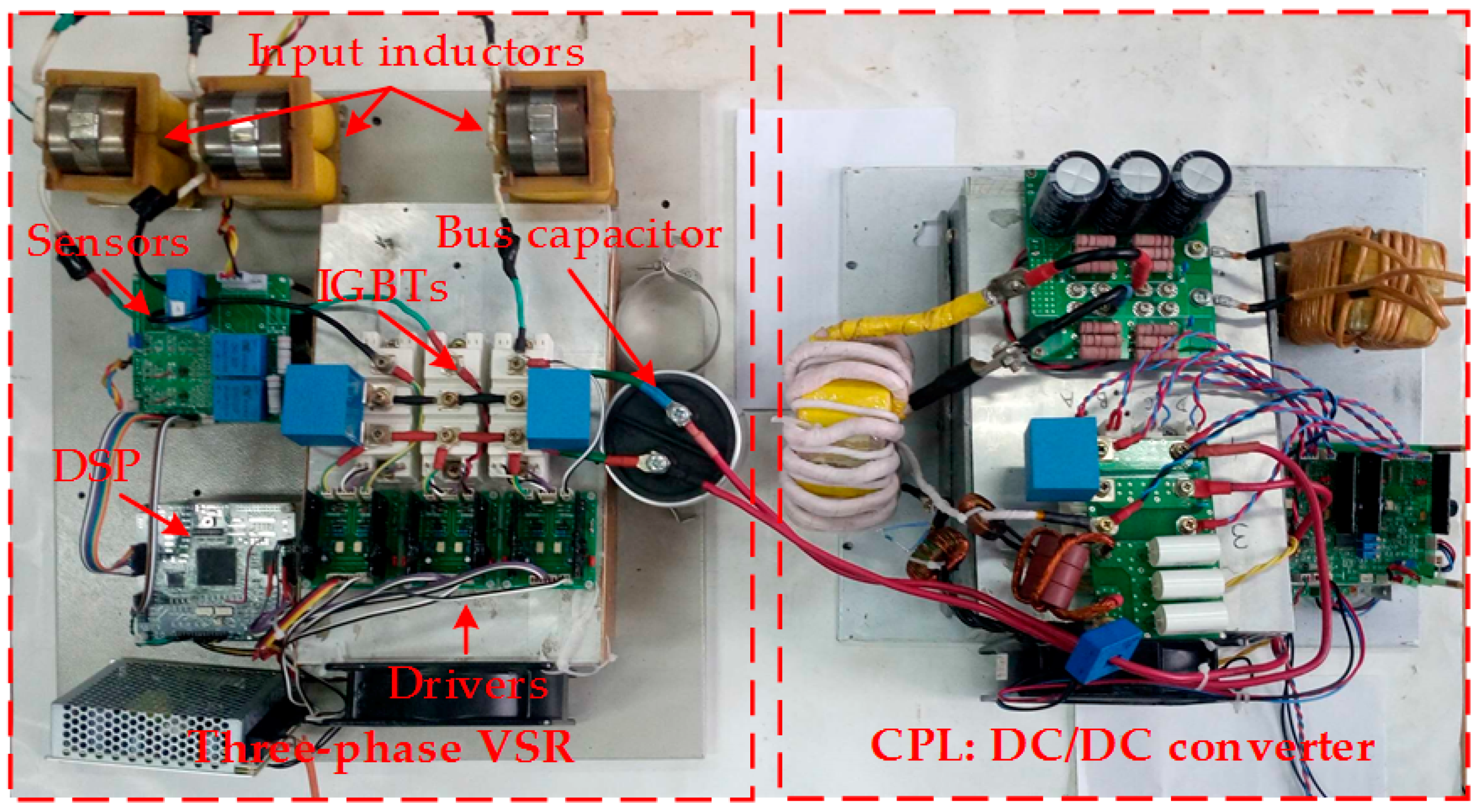
The power jump range is still analyzed by mixed potential theory in this section to discuss the stability of three-phase VSR with CPL based on ADRC. Assume z 1 = v d c 2 and b0 = b, then
z 2 = f ( y , y ˙ , u ) = 2 P C P L / C
The control function of voltage loop is given by:
i d r e f = u 0 z 2 b 0 = C K p ( V d c r e f 2 v d c 2 ) + 2 P C P L 2 e d
The control loop equations of a three-phase VSR based on ADRC are constructed by Equations (10a), (10b) and (33). The current potential function and the voltage potential function are still Equations (11) and (12) respectively. In the same way as in Section 2.3, the stability is analyzed by the theorem in the Appendix A. According to the control loop Equations (10a), (10b) and (33), the second order partial derivatives of A(i) and B(v) are solved as:
A i i _ A D R C ( i ) = [ R + K i p 0 0 R + K i p ]
B v v _ A D R C ( v ) = K p K i p C i d e d + v d i d P C P L v d c 2
According to the mixed potential stability theorem in the Appendix A, the sufficient condition for the stability of the three-phase VSR with CPL based on ADRC under large-signal perturbation is:
P C P L _ A D R C < C ( R + K i p ) 3 L v d c 2 K p K i p C v d c 2 i d e d + v d i d
Compared with the Equation (15), it can be seen that the power jump range under large-signal disturbance is different from that of PI control. Specifically, on the premise that the two methods have the same gain (i.e., Kp = Kvp), the difference between Equations (15) and (36) is determined by item M in Equation (15). The instability leads by large-signal disturbance mainly refers to the shock and divergence of the bus voltage when the CPL power increases. Therefore, under the premise of restoring stability, the minimum bus voltage must appear at the first oscillatory trough after the disturbance, as shown in Figure 7. In the process, the bus voltage reduces from Vdcref to the minimum value Vdcmin, energy in the capacitor is continuously extracted to meet the power requirement of the CPL, so edidPCPL_PI < 0, or M < 0. It can be concluded that when there is a large-signal disturbance, the power jump range of VSR based on ADRC is larger than PI control. In other words, the stability is better.

4. Experiments

To verify the proposed control methods, a prototype of the three-phase VSR with CPL as shown in Figure 8 is built and tested. The system configuration is shown in Figure 1. Detailed parameters of the three-phase VSR are listed in Table 1, and the control circuit is based on the digital signal processor (TMS320F28335). The CPL is a full bridge DC/DC converter, of which the input voltage is 650 V, the output voltage vCPL_o is 300 V, and switching frequency is 20 kHz.
Figure 9a shows the main operating waveforms of the VSR with conventional PI control. At the beginning, the load power of VSR was 2 kW, and the system operated under light load. When the load power suddenly increased to 10 kW, the bus voltage vdc and grid current ia, ib, and ic begin to oscillate until the protection was triggered and the system shut down. This indicates that this large-signal disturbance (load power suddenly increases by five times) caused the system to lose stability, and that the conventional PI control failed.
Figure 9b shows the main operating waveforms of the VSR with proposed ADRC. The other experimental conditions are the same as PI control. When the load power suddenly increased from 2 kW to 10 kW, the bus voltage vdc was quickly regulated back to the reference 650 V. In this case, the cascade system composed of VSR and CPL ran well, and the steady performance was good. The THD of grid currents was 3.5%, 3.9%, and 4% respectively. Compared with Figure 9a, the power jump range of the VSR with CPL had been effectively expanded and stability had been improved.
Figure 10 shows the main operating waveforms of the CPL when load power is changed from 2 kW to 10 kW. It can be seen that after the load power jumped, the closed-loop control of CPL makes the output voltage vCPL_o quickly back to 300 V, and the oscillation is very small. The CPL output current iCPL_o and output power PCPL also quickly reached the target value, which satisfies the CPL characteristic. This shows that the results of Figure 9 is meaningful and sufficient.

5. Conclusions

In this paper, the problem that three-phase VSRs with CPL are unstable under large-signal disturbance is discussed first. Then, based on the mixed potential theory, the stability boundary of VSR with CPL when load power jumps (a typical large-signal disturbance) is analyzed. In order to improve the large-signal stability of the system, a voltage loop control scheme based on ADRC is proposed. It was shown that the scheme expands the power jump range of the VSR effectively, and improves the disturbance rejection performance, so that it is more suitable for applications with heavy load frequently switching. Finally, the validity of the control scheme is demonstrated by experiments.

Author Contributions

B.L. analyzed the method, designed the experiments and wrote the paper. H.B. proposed the main idea. X.Z. was responsible for the theoretical derivation.

Funding

This study was supported by the National Natural Science Foundation of China (NSFC) (grants 51377036).

Acknowledgments

The authors would like to thank Yuxuan Zhu for her support and suggestions.

Conflicts of Interest

The authors declare no conflict of interest.

Appendix A. Mixed Potential Theory Stability Theorem 3

Define i = [ i L 1 i L 2 ] T , v = [ v C 1 v C 2 ] T , A i i ( i ) = 2 A ( i ) i 2 , B v v ( v ) = 2 B ( v ) v 2 , P v = P ( i , v ) v , P i = P ( i , v ) i , L = [ L 1 0 0 L 2 ] and C = [ C 1 0 0 C 2 ] . Define μ1 is the minimum eigenvalue of matrix L 1 / 2 A i i ( i ) L 1 / 2 , μ2 is the minimum eigenvalue of matrix C 1 / 2 B v v ( v ) C 1 / 2 . If all the i and v in the circuits meet
μ 1 + μ 2 > 0
and when | v | + | i | , there is
P ( i , v ) = μ 1 μ 2 2 P ( i , v ) + 1 2 P i T ( L 1 P i ) + 1 2 P v T ( C 1 P v )
Then when t , all variables of the circuit will approach the operating point, that is, no matter how the voltage and current change, the system will eventually become stable.

References

  1. Ramirez-Hernandez, J.; Araujo-Vargas, I.; Rivera, M.; Ramirez-Hernandez, J.; Araujo-Vargas, I.; Rivera, M. A Modular AC-DC Power Converter with Zero Voltage Transition for Electric Vehicles. Energies 2017, 10, 1386. [Google Scholar] [CrossRef]
  2. Nami, A.; Liang, J.; Dijkhuizen, F.; Demetriades, G.D. Modular Multilevel Converters for HVDC Applications: Review on Converter Cells and Functionalities. IEEE Trans. Power Electron. 2015, 30, 18–36. [Google Scholar] [CrossRef]
  3. Mehrasa, M.; Pouresmaeil, E.; Zabihi, S.; Vechiu, I.; Catalao, J.P.S. A multi-loop control technique for the stable operation of modular multilevel converters in HVDC transmission systems. Int. J. Electr. Power Energy Syst. 2018, 96, 194–207. [Google Scholar] [CrossRef]
  4. Zhang, X.; Zhong, Q.C.; Ming, W.L. Stabilization of a Cascaded DC Converter System via Adding a Virtual Adaptive Parallel Impedance to the Input of the Load Converter. IEEE Trans. Power Electron. 2015, 31, 1826–1832. [Google Scholar] [CrossRef]
  5. Du, W.; Zhang, J.; Zhang, Y.; Qian, Z. Stability Criterion for Cascaded System with Constant Power Load. IEEE Trans. Power Electr. 2013, 28, 1843–1851. [Google Scholar] [CrossRef]
  6. Mishima, T.; Akamatsu, K.; Nakaoka, M. A High Frequency-Link Secondary-Side Phase-Shifted Full-Range Soft-Switching PWM DC–DC Converter with ZCS Active Rectifier for EV Battery Chargers. IEEE Trans. Power Electr. 2013, 28, 5758–5773. [Google Scholar] [CrossRef]
  7. Shin, S.C.; Lee, H.J.; Kim, Y.H.; Lee, J.H.; Won, C.Y. Transient Response Improvement at Startup of a Three-Phase AC/DC Converter for a DC Distribution System in Commercial Facilities. IEEE Trans. Power Electron. 2014, 29, 6742–6753. [Google Scholar] [CrossRef]
  8. Cao, W.; Mecrow, B.C.; Atkinson, G.J.; Bennett, J.W.; Atkinson, D.J. Overview of Electric Motor Technologies Used for More Electric Aircraft (MEA). IEEE Trans. Ind. Electron. 2012, 59, 3523–3531. [Google Scholar] [CrossRef]
  9. Verma, A.K.; Jain, C.; Singh, B.; Shahani, D.T. Adaptive noise cancellation based harmonic elimination in grid integrated photovoltaic system. IET Renew. Power Gener. 2016, 10, 1096–1104. [Google Scholar] [CrossRef]
  10. Huang, M.; Peng, Y.; Chi, K.T.; Liu, Y.; Sun, J.; Zha, X. Bifurcation and large-signal stability analysis of three-phase voltage source converter under grid voltage dips. IEEE Trans. Power Electron. 2017, 32, 8868–8879. [Google Scholar] [CrossRef]
  11. Mehrasa, M.; Pouresmaeil, E.; Zabihi, S.; Catalao, J.P.S. Dynamic model, control and stability analysis of MMC in HVDC transmission systems. IEEE Trans. Power Deliv. 2016, 32, 1471–1482. [Google Scholar] [CrossRef]
  12. Mehrasa, M.; Pouresmaeil, E.; Zabihi, S.; Rodrigues, E.M.G.; Catalão, J.P.S. A control strategy for the stable operation of shunt active power filters in power grids. Energy 2016, 96, 325–334. [Google Scholar] [CrossRef]
  13. Pouresmaeil, E.; Shaker, H.R.; Mehrasa, M.; Shokridehaki, M.A.; Rodrigues, E.M.G. Stability analysis for operation of DG units in smart grids. In Proceedings of the IEEE International Conference on Power Engineering, Energy and Electrical Drives, Riga, Latvia, 11–13 May 2015; pp. 447–452. [Google Scholar]
  14. Pouresmaeil, E.; Bo, N.; Mehrasa, M.; Erdinc, O.; Catalao, J.P.S. A control algorithm for the stable operation of interfaced converters in microgrid systems. In Proceedings of the Innovative Smart Grid Technologies Conference Europe, Istanbul, Turkey, 12–15 October 2014; pp. 1–6. [Google Scholar]
  15. Rahimi, A.M.; Emadi, A. Active Damping in DC/DC Power Electronic Converters: A Novel Method to Overcome the Problems of Constant Power Loads. IEEE Trans. Ind. Electron. 2009, 56, 1428–1439. [Google Scholar] [CrossRef]
  16. Liu, X.; Zhou, Y.; Zhang, W.; Ma, S. Stability Criteria for Constant Power Loads with Multistage LC Filters. IEEE Trans. Veh. Technol. 2011, 60, 2042–2049. [Google Scholar] [CrossRef]
  17. Zhang, M.; Li, Y.; Liu, F.; Luo, L.; Cao, Y.; Shahidehpour, M. Voltage Stability Analysis and Sliding Mode Control Method for Rectifier in DC Systems with Constant Power Loads. IEEE J. Emerg. Sel. Top. Power Electr. 2017, 5, 1621–1630. [Google Scholar] [CrossRef]
  18. Mitchell, D.M. Damped EMI Filters for Switching Regulators. IEEE Trans. Electromagn. Compat. 1978, EMC-20, 457–463. [Google Scholar] [CrossRef]
  19. Cespedes, M.; Xing, L.; Sun, J. Constant-Power Load System Stabilization by Passive Damping. IEEE Trans. Power Electr. 2011, 26, 1832–1836. [Google Scholar] [CrossRef]
  20. Liu, B.; Ben, H.; Zhang, X.; Meng, T.; Wang, X. Stabilization of a cascaded AC/DC system based on small signal analysis, in Book Stabilization of a cascaded AC/DC system based on small signal analysis. In Proceedings of the International Conference on Electrical Machines and Systems, Sydney, Australia, 11–14 August 2017; pp. 1–6. [Google Scholar]
  21. Hatua, K.; Jain, A.K.; Banerjee, D.; Ranganathan, V.T. Active Damping of Output LC Filter Resonance for Vector-Controlled VSI-Fed AC Motor Drives. IEEE Trans. Ind. Electron. 2012, 59, 334–342. [Google Scholar] [CrossRef]
  22. Dannehl, J.; Liserre, M.; Fuchs, F.W. Filter-Based Active Damping of Voltage Source Converters with LCL Filter. IEEE Trans. Ind. Electron. 2011, 58, 3623–3633. [Google Scholar] [CrossRef]
  23. Liu, S.; Zhou, L.; Lu, W. Simple analytical approach to predict large-signal stability region of a closed-loop boost DC–DC converter. IET Power Electron. 2013, 6, 488–494. [Google Scholar] [CrossRef]
  24. Weaver, W.W.; Iii, R.D.R.; Wilson, D.G.; Matthews, R.C. Metastability of Pulse Power Loads Using the Hamiltonian Surface Shaping Method. IEEE Trans. Energy Convers. 2017, 32, 820–828. [Google Scholar] [CrossRef]
  25. Zhang, X.N.; Vilathgamuwa, D.M.; Foo, G.; Tseng, K.J.; Kandasamy, K.; Gupta, A.K.; Chandana, G. Cascaded sliding mode control for global stability of three phase AC/DC PWM rectifier with rapidly varying power electronic loads. In Proceedings of the 39th Annual Conference of the IEEE Industrial Electronics Society, Vienna, Austria, 10–14 November 2013; pp. 4580–4587. [Google Scholar]
  26. Magne, P.; Nahid-Mobarakeh, B.; Pierfederici, S. Dynamic Consideration of DC Microgrids with Constant Power Loads and Active Damping System—A Design Method for Fault-Tolerant Stabilizing System. IEEE J. Emerg. Sel. Top. Power Electron. 2014, 2, 562–570. [Google Scholar] [CrossRef]
  27. Zhang, W.; Hou, Y.; Liu, X.; Zhou, Y. Switched Control of Three-Phase Voltage Source PWM Rectifier Under a Wide-Range Rapidly Varying Active Load. IEEE Trans. Power Electr. 2012, 27, 881–890. [Google Scholar] [CrossRef]
  28. Zhang, P.H.; Yang, G.J.; Tie-Cai, L.I. Direct Voltage Control of Three-phase PWM Rectifier Based on Feedback Linearization. Proc. CSEE 2010, 30, 39–46. [Google Scholar] [CrossRef]
  29. Han, J. From PID to Active Disturbance Rejection Control. IEEE Trans. Ind. Electron. 2009, 56, 900–906. [Google Scholar] [CrossRef]
  30. Tian, J.; Zhang, S.; Zhang, Y.; Li, T. Active disturbance rejection control based robust output feedback autopilot design for airbreathing hypersonic vehicles. ISA Trans. 2018, 74, 45–59. [Google Scholar] [CrossRef] [PubMed]
  31. Xiao, Y.; Hong, Y.; Chen, X.; Huo, W. Switching control of wind turbine sub-controllers based on an active disturbance rejection technique. Energies 2016, 9, 793. [Google Scholar] [CrossRef]
  32. Brayton, R.K.; Moser, J.K. A theory of nonlinear networks. I. Q. Appl. Math. 1964, 2, 1–33. [Google Scholar] [CrossRef]
  33. Jeltsema, D.; Scherpen, J.M.A. On Brayton and Moser’s missing stability theorem. IEEE Trans. Circuits Syst. II Express Briefs 2005, 52, 550–552. [Google Scholar] [CrossRef]
Figure 1. Schematic of three-phase VSR cascaded with a DC-input converter.
Energies 11 01706 g001
Figure 2. The circuit of voltage source in series with CPL.
Energies 11 01706 g002
Figure 3. The equivalent circuit of three-phase VSR with CPL in dq coordinates.
Energies 11 01706 g003
Figure 4. Control block diagram of the three-phase VSR with conventional PI control.
Energies 11 01706 g004
Figure 5. General structure of ADRC.
Energies 11 01706 g005
Figure 6. Control block of the voltage loop of three-phase VSR based on ADRC.
Energies 11 01706 g006
Figure 7. Bus voltage under large-signal disturbance (power sudden increase).
Energies 11 01706 g007
Figure 8. Prototype of the three-phase VSR with CPL.
Energies 11 01706 g008
Figure 9. Main operating waveforms of the VSR when load power is changed from 2 kW to 10 kW. (a) with conventional PI control; (b) with the proposed ADRC.
Energies 11 01706 g009
Figure 10. Main operating waveforms of the CPL when load power is changed from 2 kW to 10 kW. (a) with conventional PI control; (b) with the proposed ADRC.
Energies 11 01706 g010
Table 1. Circuit Parameters of the Three-phase VSR.
SymbolQuantityValue
EabcGrid phase voltage220 V
fgGrid frequency50 Hz
fsPWM frequency16 kHz
LInput inductance3.2 mH
VdcrefBus voltage650 V
REquivalent resistance0.2 Ω
CBus capacitance100 μF
KipProportional gain of the current PI regulator5
KiiIntegral gain of the current PI regulator100
KvpProportional gain of the voltage PI regulator0.2
KviIntegral gain of the voltage PI regulator80

