Article

A Novel Output Power Control of Wireless Powering Kitchen Appliance System with Free-Positioning Feature

by
Supapong Nutwong
,
Anawach Sangswang
*,
Sumate Naetiladdanon
and
Ekkachai Mujjalinvimut
Department of Electrical Engineering, Faculty of Engineering, King Mongkut’s University of Technology Thonburi, Bangkok 10140, Thailand
*
Author to whom correspondence should be addressed.
Energies 2018, 11(7), 1671; https://doi.org/10.3390/en11071671
Submission received: 8 June 2018 / Revised: 22 June 2018 / Accepted: 22 June 2018 / Published: 27 June 2018
(This article belongs to the Special Issue Wireless Power Transfer 2018)

Abstract

:
To achieve a free-positioning wireless power transfer (WPT) system, the output power must be regulated throughout the operation. This paper presents a novel output power control of a WPT system, based on the model predictive control (MPC). The output power is predicted by utilizing the system’s mathematical model. The optimal duty cycle for a desired output power is obtained through the minimization of the objective function, which is simple and easy to implement, with no need for gain tuning. The proposed controller is implemented on the primary side, without any measurement or communication devices on the secondary side. This reduces the cost, size, and complexity of the WPT system. The load resistance and mutual inductance identification method is also introduced. It is based on the reflected impedance knowledge, where only the information of primary current is required. Experimental results of the output power step response show better performance compared with conventional Proportional-Integral (PI) control. The proposed controller is experimentally validated on a 200 W kettle. The output power can be kept constant at 200 W while the kettle is laterally moved. With the proposed controller, the kettle can be placed freely up to 7 cm from the align position, which is 63.64% of the primary coil’s outer radius.

1. Introduction

Wireless power transfer (WPT) is an innovative technique to send electric power across an air gap via the electromagnetic induction of a coupled coil, commonly found among battery charging and powering equipment wirelessly. It can be used to transfer power in a hostile environment, for example underground and underwater [1,2,3]. The concept of WPT has been well-perceived and can be found in many applications, such as biomedical implants [4], wearable devices [5], wireless sensors [6], and portable devices [7]. Higher power applications include robots [8], electric vehicles [9], and trams [10]. As the demand for convenience is increased, WPT has found widespread applications in modern home appliances, namely LED TVs [11], kitchen appliances [12], and stage lighting systems [13]. Future trends in WPT applications are focusing on wireless networks and internet of things [14,15,16,17,18].
The advancement of smart household devices has enabled kitchen appliances, such as kettles, rice cookers, and electric heaters to operate wirelessly. The galvanic isolation between power source and heating load provides important advantages, including safety from electric shock and convenient operation. Furthermore, the free-positioning feature, where the heating load is placed freely in a designed specific area, can be obtained from the WPT technique [19,20]. However, the misalignment between a coupled coil is inevitable from this feature. This results in a mutual inductance variation, which causes the output power to vary. The equivalent resistance of a heating load changes with the temperature, which also alters the output power. Therefore, the control of output power is indispensable. To reduce the cost, size, and complexity of the WPT system, the controller should be implemented on the primary side, without any measurement and communication devices on the secondary side [21,22,23]. The primary-side control can be realized through the inverter voltage control. To regulate the inverter output voltage, the phase-shift control [24,25] is a commonly used technique in the WPT system because the output voltage contains no DC component. Moreover, its harmonic contents are less than those of asymmetrical duty cycle (ADC) control [26] and asymmetrical clamped mode (ACM) control technique [27].
In order to regulate the output power based on primary-side control method, the load resistance and mutual inductance must be identified throughout the operation. Previous research effort on load resistance and mutual inductance identification utilizing only the primary-side measured variables have been reported in [28,29,30]. The identification method of the load impedance and mutual inductance in steady-state is presented in [28]. By switching an additional compensation capacitor into the primary circuit, the system will be operated in two different modes where the identification formulas of both load impedance and mutual inductance can be derived. However, an extra capacitor, switches, and control are required. This increases the component counts, cost, and complexity of the WPT system. The online estimation method presented in [29] is based on the Goertzel algorithm and the mean-squared errors corresponding to all mutual inductance values are evaluated. This method requires a high computational effort. Thus, it is difficult to implement and time consuming. In [30], load resistance and mutual inductance can be estimated simultaneously by the measurement of input voltage and current. Unfortunately, the estimation fails at the resonant frequency due to a mathematical problem.
Among the existing control schemes for power electronics applications, model predictive control (MPC) could be considered as a straightforward technique. It is easy to implement on digital control, with low computational burden. This control approach utilizes the system’s mathematical model to achieve the optimal controlled variable, which is simple and doesn’t require gain tuning. The MPC technique has been successfully used in many applications, such as electric motor drive [31,32], grid-connected inverter [33,34], induction melting [35], and ultrasonic cleaning [36]. Taking the advantages of MPC technique, this paper presents a novel output power control of WPT system based on the model predictive strategy. The controller is implemented on the primary side, without any measurement and communication devices on the secondary side. The method of load resistance and mutual inductance identification is also introduced. The presented method is based on the reflected impedance knowledge, where the identification formulas are derived from the reflected resistance and reactance. This method measures only the primary current. The issue of operation at the resonant frequency as in [30] has been addressed. The performance of the proposed MPC is compared with conventional PI control via the experiment of output power step response. The proposed controller is experimentally validated on a 200 W kettle. This paper is organized as follows: The analysis of system’s mathematical model, selection of the optimal operating frequency, and proposed method of load resistance and mutual inductance identification are introduced in Section 2. The full-bridge inverter with phase-shift control, proposed predictive output power control, and system protection are detailed in Section 3. The verification of the proposed controller is shown in Section 4 via experimental results. The conclusion is presented in Section 5.

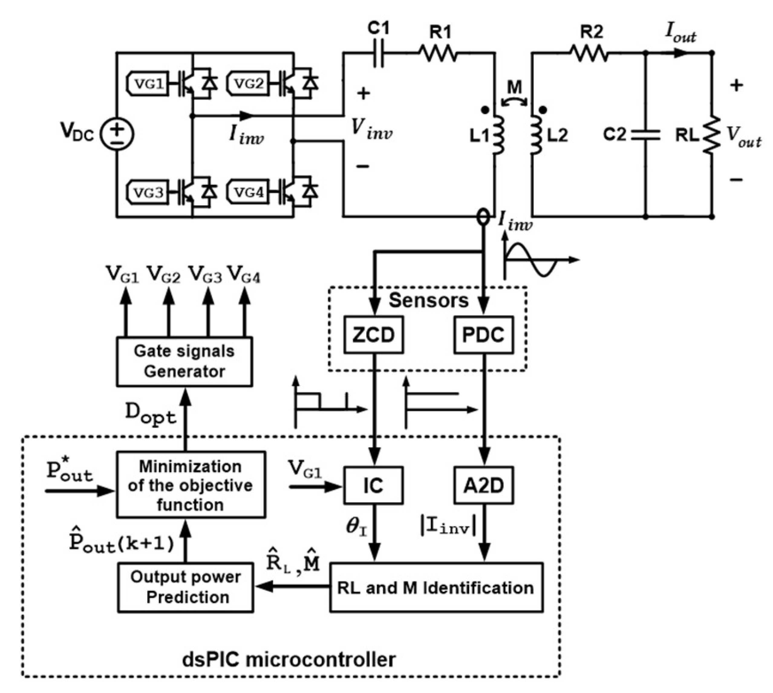
2. Theoretical Analysis

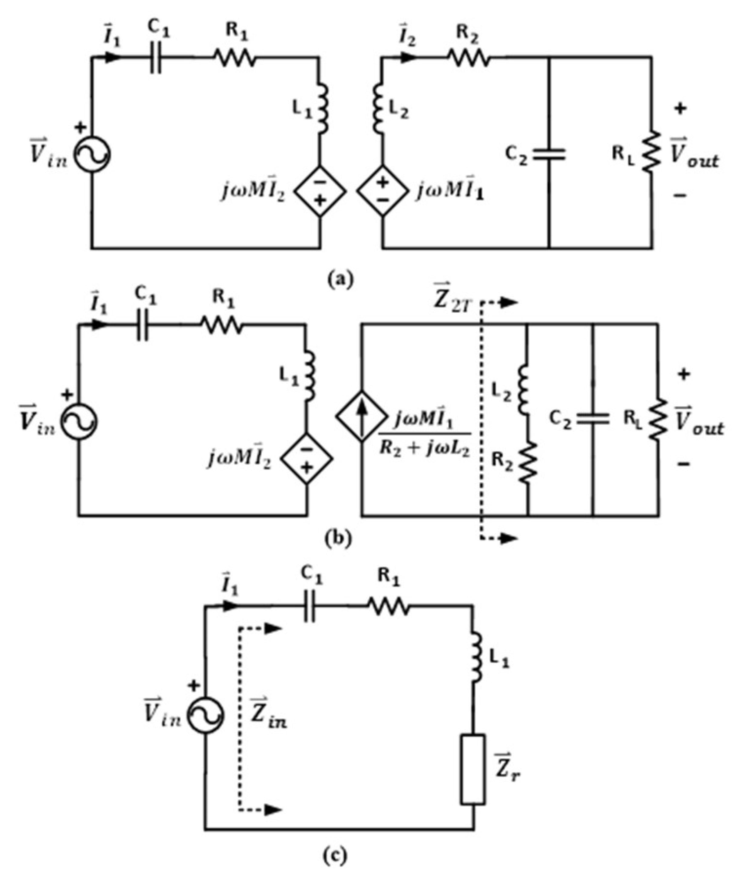
2.1. System Characteristic

The WPT system, as shown in Figure 1, is analyzed in this paper. It consists of a DC power supply, full-bridge inverter, primary or transmitter coil, secondary or receiver coil, compensation capacitors, heating load, and primary-side controller. The kettle is a heating load of the system. In practical operation of the WPT system for kitchen appliances, the vertical distance between the coupled coil and air gap is fixed. Thus, only horizontal misalignment caused by lateral movement of the secondary coil is considered. In this work, the air gap is fixed at 1 cm, while the maximum horizontal misalignment is at 7 cm. Since the WPT system exhibits a high-quality factor (Q) circuit behavior, only the fundamental component of the inverter voltage is taken into account.
A commonly used model for WPT system analysis is the mutual inductance coupling model, as shown in Figure 2a, for the series-parallel (SP) topology [37]. The primary winding is supplied by a sinusoidal voltage source ( V i n ). The compensation capacitor C1 is connected in series with the primary coil, where C2 is connected in parallel with the secondary coil, forming the SP circuit topology. The coupled coil has mutual inductance M, and self-inductances of the primary and secondary coils, denoted by L1 and L2, respectively. The winding resistances of both coils are R1 and R2. Load of the system is represented by RL, which is the equivalent resistance of a kettle’s heater.
In this paper, the theoretical analysis of the system is based on the following assumptions:
(1)
Both self-inductances, L1 and L2, are fixed and independent of misalignment. This is due to the absence of magnetic material, such as ferrite bars, along both primary and secondary coils.
(2)
The winding resistances, R1 and R2, of the coupled coil are constant, since the operating frequency is fixed and the heating effect on the windings is negligible.
(3)
The compensation capacitors, C1 and C2, are constant under normal operating condition.
Using the source transformation technique, voltage source in the secondary circuit of Figure 2a is transformed to be the current source, as shown in Figure 2b. The sum of impedance in secondary circuit is obtained by:
Z 2 T = ω 2 L 2 2 R L + R 2 2 R L + R 2 R L 2 j ( ω 3 L 2 2 C 2 R L 2 + ω C 2 R 2 2 R L 2 ω L 2 R L 2 ) ω 4 L 2 2 C 2 2 R L 2 + ω 2 C 2 R L 2 ( C 2 R 2 2 2 L 2 ) + ω 2 L 2 2 + R 2 2 + R L 2 + 2 R 2 R L
where ω is the operating angular frequency in radian per second. The resonant frequency of the secondary circuit in Figure 2b is given as:
f 02 = 1 2 π 1 L 2 C 2 R 2 2 L 2 2
The reflected impedance referred to the primary circuit as illustrated in Figure 2c is defined as:
Z r = R r + j X r
where the reflected resistance and reactance are given as:
R r = ω 2 M 2 ( ω 2 C 2 2 R 2 R L 2 + R 2 + R L ) ω 4 L 2 2 C 2 2 R L 2 + ω 2 C 2 R L 2 ( C 2 R 2 2 2 L 2 ) + ω 2 L 2 2 + R 2 2 + R L 2 + 2 R 2 R L
X r = ω 3 M 2 ( ω 2 L 2 C 2 2 R L 2 C 2 R L 2 + L 2 ) ω 4 L 2 2 C 2 2 R L 2 + ω 2 C 2 R L 2 ( C 2 R 2 2 2 L 2 ) + ω 2 L 2 2 + R 2 2 + R L 2 + 2 R 2 R L
The reflected reactance in (5) is changed from capacitive to inductive reactance, as load resistance is greater than the limit value, which is defined by:
R L , l i m i t = L 2 ( C 2 ω 2 L 2 C 2 2 )
By using the designed circuit parameters listed in Table 1, the relationship between the reflected reactance ( X r ) and the load resistance ( R L ) for different mutual inductances (M) is shown in Figure 3. Clearly, the R L , l i m i t is at 1500 ohms for both mutual inductances. Note that the equivalent resistance of the kettle’s heater is typically less than 100 ohms. The reflected reactance in (5) can be considered capacitive and denoted by X c r .
The input impedance in Figure 2c is defined as:
Z i n = Z 1 + Z r = R 1 + R r + j ( ω L 1 1 ω C 1 X c r )
where Z 1 = R 1 + j ( ω L 1 1 / ω C 1 ) . The input impedance angle is expressed as:
θ Z i n = tan 1 ( Im { Z i n } Re { Z i n } )
Note that θ Z i n becomes zero when the input voltage, V i n , and current, I 1 , are in-phase, that is, the system is operated at primary zero phase angle frequency ( f z p a ). By operating at f z p a , the VA rating of the input power supply is minimized, for the same output power [37]. For a targeted f z p a , the primary capacitance is given as:
C 1 = 1 2 π f z p a ( 2 π f z p a L 1 X c r )
In this work, primary zero phase angle frequency is designed to be equal to secondary resonant frequency ( f z p a = f 02 ). Using (9), the required value of C 1 is obtained, which is already indicated in Table 1.

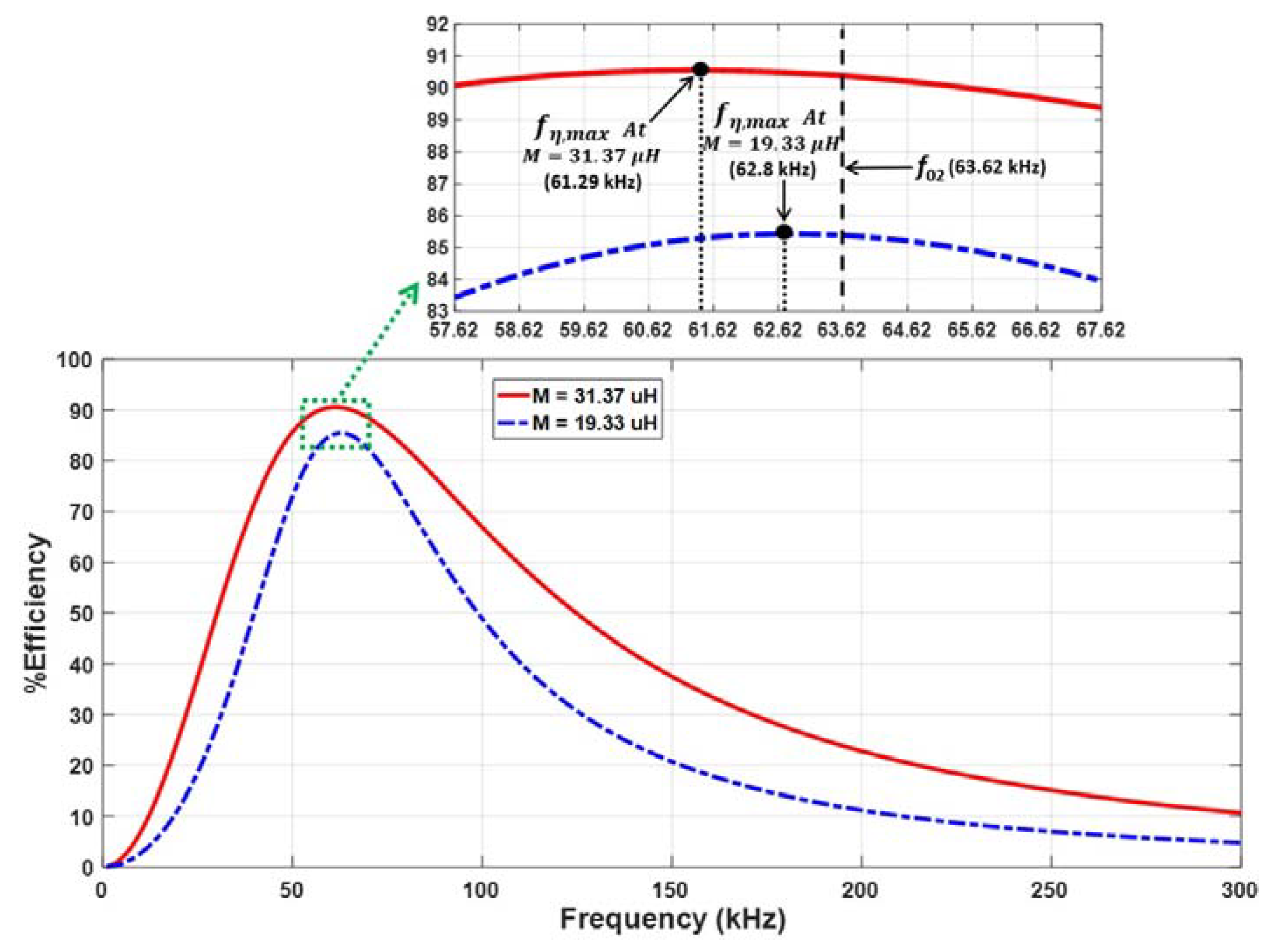
2.2. Optimal Operating Frequency

The optimal operating frequency of the system is investigated in this part, with the objective of maximum efficiency operation. The output power is given as:
P o u t = ω 2 M 2 | V i n | 2 | Z 2 T | 2 2 R L | Z i n | 2 ( R 2 2 + ω 2 L 2 2 )
where | Z 2 T | , | Z i n | , | V i n | , and | V o u t | are the magnitudes of Z 2 T , Z i n , V i n , and V o u t , respectively. The input power is defined by:
P i n = | V i n | 2 cos ( θ Z i n ) 2 | Z i n |
With (10) and (11), the system efficiency is derived as:
η = ω 2 M 2 | Z 2 T | 2 R L ( R 2 2 + ω 2 L 2 2 ) | Z i n | cos ( θ Z i n )
With the necessary condition of the maximum efficiency, the desired frequency ( f η , max ) is obtained as:
f η , max = 1 2 π ( R 2 + R L ) R 1 ( L 2 2 R 1 + M 2 R 2 ) R L C 2 ( L 2 2 R 1 + M 2 R 2 )
By using the circuit parameters in Table 1, f η , max are 61.29 and 62.8 kHz for the mutual inductances of 31.37 and 19.33 μH, respectively. Since the primary zero phase angle frequency is equal to the secondary resonant frequency, both f η , max values are less than f z p a , which can lead to a non-ZVS operation of the inverter. Figure 4 shows the relationship between the system efficiency and the operating frequency under two different mutual inductances. To avoid the non ZVS operation, f 02 is selected as the switching frequency of the inverter. A tradeoff is that the theoretical efficiency is reduced by 0.2% and 0.05% for the mutual inductances of 31.37 μH and 19.33 μH, respectively, as shown in the magnified version of the figure. In the proposed SP topology, if the operating frequency is moved away from the designated frequency, the efficiency is dominated by the reduction of the | Z 2 T | term and is greatly reduced no matter which direction the frequency is changed. This means that the controller must be able to estimate the related impedance and assign the proper operating frequency to maintain the desired system efficiency throughout the operation. With the fixed frequency operation, the reflected impedance is simplified and the control of the WPT system can be realized on a microcontroller.

2.3. Load Resistance and Mutual Inductance Identification

In this work, the measurement and control have been implemented only on the primary side. To control the output power during operation, the values of RL and M must be identified throughout the operation. The online identification method of mutual inductance and load resistance is introduced in this part. From (4) and (5), with a substitution of ω by ω 02 , both load resistance and mutual inductance can be estimated. At ω 02 , the reflected resistance ( R r ) and reactance ( X c r ) become:
R r = ω 02 2 M 2 [ ω 02 2 L 2 2 ( R 2 + R L ) + R 2 3 ] ( ω 02 2 L 2 2 + R 2 2 ) ( ω 02 2 L 2 2 + R 2 2 + R 2 R L )
X c r = ω 02 3 M 2 L 2 [ ω 02 2 L 2 2 + R 2 2 R 2 R L ] ( ω 02 2 L 2 2 + R 2 2 ) ( ω 02 2 L 2 2 + R 2 2 + R 2 R L )
The load resistance can be derived as:
R L = R r ( ω 02 3 L 2 3 + ω 02 L 2 R 2 2 ) X c r ( ω 02 2 L 2 2 R 2 + R 2 3 ) ω 02 2 L 2 2 X c r + ω 02 L 2 R 2 R r
With the measured input voltage and current, the reflected resistance and reactance in Figure 2c can be calculated as:
R r = | V i n | | I 1 | cos ( θ Z i n ) R 1
X c r = ω 02 L 1 1 ω 02 C 1 | V i n | | I 1 | sin ( θ Z i n )
From (16), the load resistance can be identified by only the primary-side measurement, without the need of the mutual inductance information, and given as:
R L = [ | V i n | | I 1 | cos ( θ Z i n ) R 1 ] ( ω 02 3 L 2 3 + ω 02 L 2 R 2 2 ) [ ω 02 L 1 1 ω 02 C 1 | V i n | | I 1 | sin ( θ Z i n ) ] ( ω 02 2 L 2 2 R 2 + R 2 3 ) ω 02 2 L 2 2 [ ω 02 L 1 1 ω 02 C 1 | V i n | | I 1 | sin ( θ Z i n ) ] + ω 02 L 2 R 2 [ | V i n | | I 1 | cos ( θ Z i n ) R 1 ] .
Similarly, the mutual inductance can be identified by:
M = [ | V i n | | I 1 | cos ( θ Z i n ) R 1 ] ( ω 02 2 L 2 2 + R 2 2 ) ( ω 02 2 L 2 2 + R 2 2 + R 2 R L ) ω 02 2 [ ω 02 2 L 2 2 ( R 2 + R L ) + R 2 3 ]
From the identified load resistance and mutual inductance, the output power can be estimated and controlled throughout the operation.

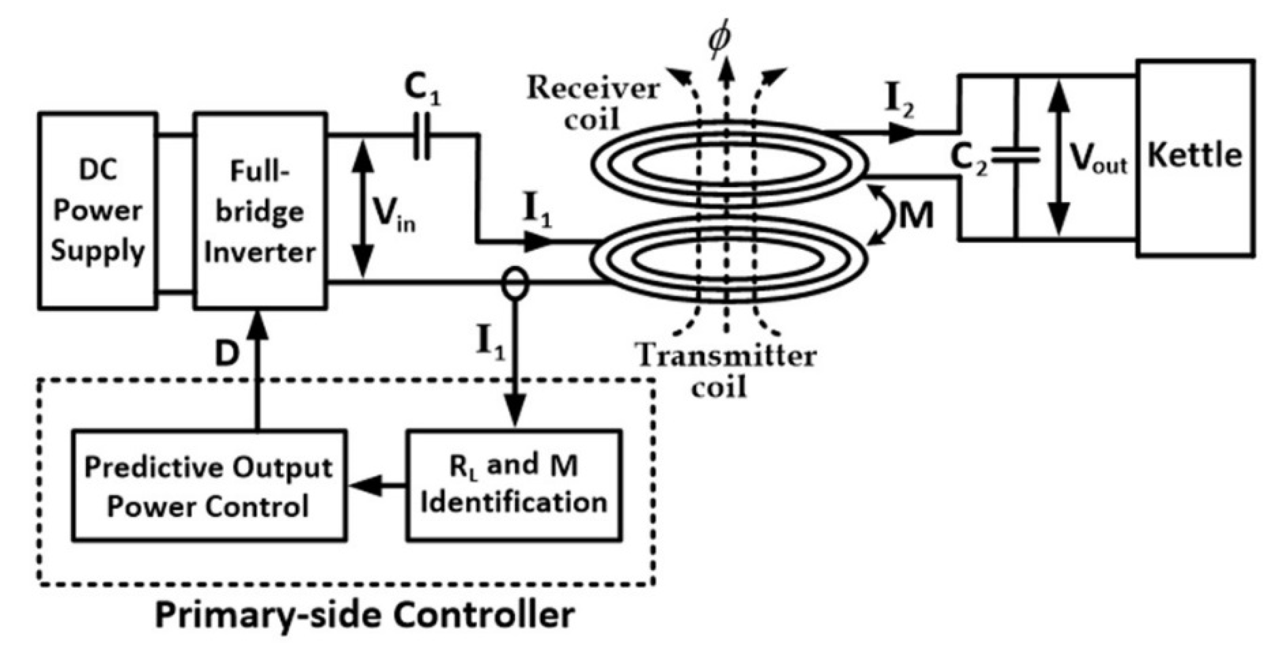
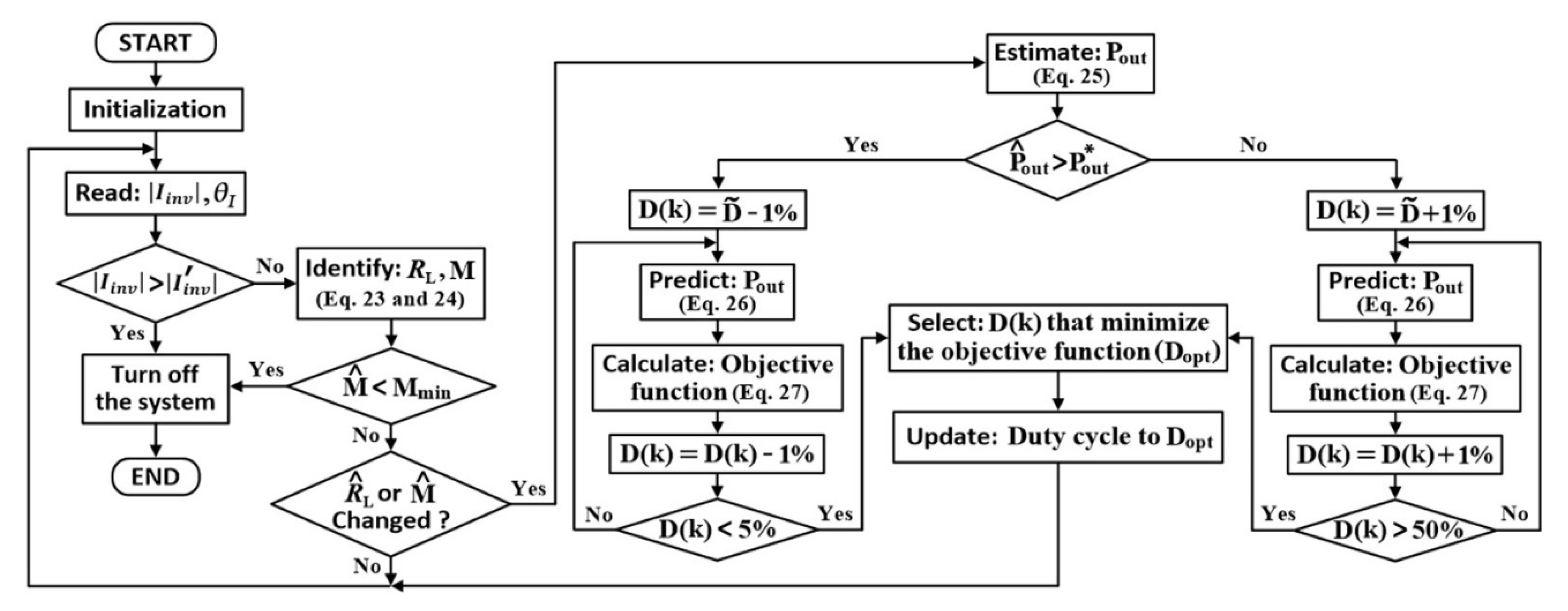
3. Proposed Controller

An important drawback of the free-positioning feature in a WPT system is mutual inductance variation. The equivalent resistance of the kettle’s heater is increased with temperature. This results in a complication in output regulation. With the aim to reduce cost, size, and complexity due to additional sensors on the secondary side, the proposed output control is based on the primary side.

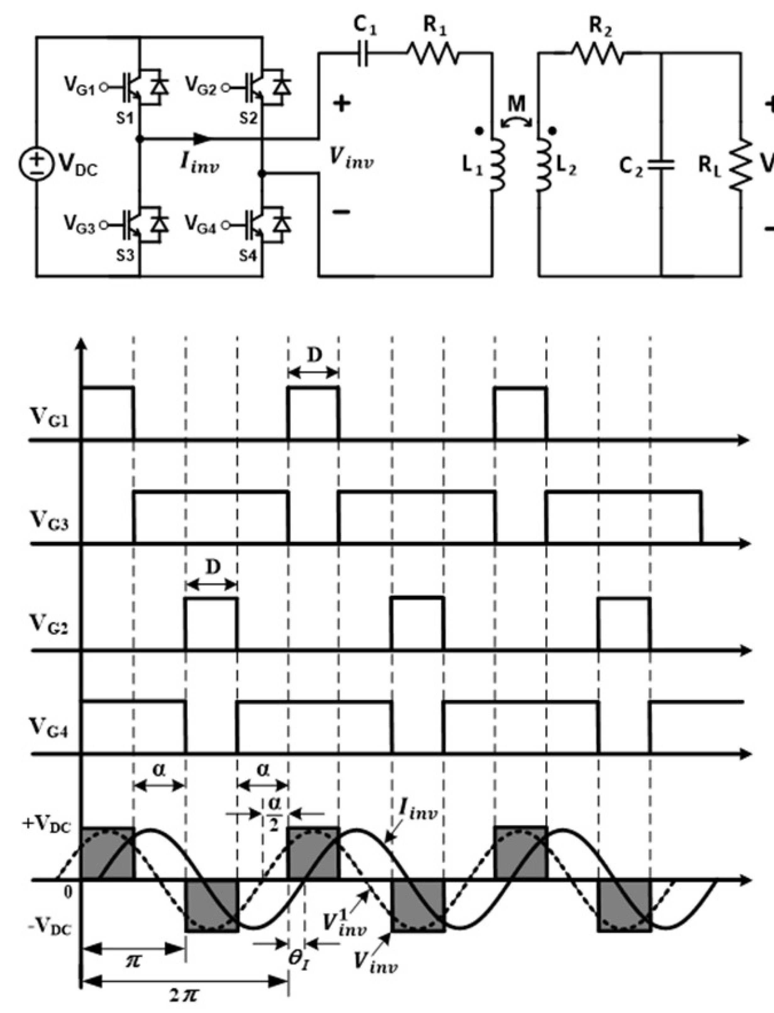
3.1. Full-Bridge Inverter with Phase-Shift Control

A full-bridge inverter is frequently used as the input power supply for the primary circuit of a WPT system. The phase-shift control is adopted for output power regulation. Gate signals and the corresponding waveforms of the full-bridge inverter with the phase-shift control are shown in Figure 5. The gate signals VG1 and VG2 operate in a complementary manner to VG3 and VG4, respectively. The duty cycle (D) of VG1 is equal to that of VG2, and the phase difference of VG1 and VG2 is equal to 180°. The amplitude of the fundamental component of the inverter voltage ( V i n v ) is given as:
| V i n v 1 | = 4 V D C π cos ( α 2 )
where V D C is the input DC voltage.
The voltage, | V i n v 1 | , can be regulated by adjusting the angle, α . This can be achieved by controlling the duty cycle, D, of the gate signals, where α = π ( 1 2 D ) , as shown in Figure 5. The desired angle, α , and D can be adjusted from 0–π and 0–50%, respectively. A typical SP topology WPT system is operated with a relatively high Q load. That is, the inverter current ( I i n v ) is essentially interchangeable with its fundamental component, where the phase difference between V i n v 1 and I i n v is equivalent to θ Z i n . The angle, θ I , represents a phase difference between V i n v and I i n v , where the rising edge of V i n v is taken as the reference. The input impedance angle can be obtained by:
θ Z i n = α 2 + θ I
From (19) and (20), the identification of load resistance and mutual inductance can be realized by:
R L = ( λ R 1 ) ( ω 02 3 L 2 3 + ω 02 L 2 R 2 2 ) ( ω 02 L 1 1 ω 02 C 1 β ) ( ω 02 2 L 2 2 R 2 + R 2 3 ) ω 02 2 L 2 2 ( ω 02 L 1 1 ω 02 C 1 β ) + ω 02 L 2 R 2 ( λ R 1 )
M = ( λ R 1 ) ( ω 02 2 L 2 2 + R 2 2 ) ( ω 02 2 L 2 2 + R 2 2 + R 2 R L ) ω 02 2 [ ω 02 2 L 2 2 ( R 2 + R L ) + R 2 3 ]
where λ = 4 V D C π | I 1 | cos ( α / 2 ) cos ( θ Z i n ) and β = 4 V D C π | I 1 | cos ( α / 2 ) sin ( θ Z i n ) . If the DC input voltage ( V D C ) is constant, the load resistance and mutual inductance can be identified by measuring the magnitude and phase of the primary current ( I 1 ) only. From (10), the output power can be estimated online throughout the operation as:
P ^ o u t = 8 V D C 2 ω 02 2 ( M ^ ) 2 | Z 2 T | 2 cos 2 [ π ( 0.5 D ) ] π 2 R ^ L | Z i n | 2 ( R 2 2 + ω 02 2 L 2 2 )
where R ^ L and M ^ are identified values of load resistance and mutual inductance, respectively. It is noted that the output power can be regulated by adjusting the duty cycle, D of the gate signals.

3.2. Model Predictive Control

As mentioned earlier, the output power is varying with the change in mutual inductance and load resistance. A power regulation capability is imperative to accommodate for the free-positioning feature (i.e., the secondary coil is placed freely in a specific area). The model-based predictive control is adopted in this work due to its simplicity, with no need for gain tuning. Through the system mathematical model, the output power can be predicted and the optimal duty cycle can be obtained. For the search space, the duty cycle, D is varied from its minimum to maximum value (0–50%). The output power can be predicted as:
P ^ o u t ( k + 1 ) = 8 V D C 2 ω 02 2 ( M ^ ) 2 | Z 2 T | 2 cos 2 ( 90 ° 180 ° D ( k ) ) π 2 R ^ L | Z i n | 2 ( R 2 2 + ω 02 2 L 2 2 )
where D ( k ) is one of the feasible duty cycle value to be substituted. The predicted output power is then compared with a desired output power ( P o u t * ) in the following objective function:
J = | P o u t * P ^ o u t ( k + 1 ) |
The optimal duty cycle, defined as D o p t , can be obtained by selecting one of D ( k ) that minimized the objective function.

3.3. Protection

While the system is operating, a kettle may be placed outside the designed area or taken away from the primary coil. From (10), the required primary current is provided as:
| I 1 | = 2 R L P o u t ( R 2 2 + ω 2 L 2 2 ) ω M | Z 2 T |
If the kettle is placed beyond a designed maximum misalignment of 7 cm from the center of primary coil, the mutual inductance is greatly decreased and the primary current is increased and can even be greater than the limit value. Moreover, the loss in the primary coil is increased resulted in a reduced system efficiency. There is a need to monitor the mutual inductance, M ^ , compared with the minimum allowable value of the mutual inductance ( M min ) throughout the operation. On the other hand, if the kettle is abruptly removed while it is powering wirelessly, the primary current is greatly increased. Such a current can lead to damage to the primary coil and inverter’s switches. This is due to the fact that the reflected impedance, Z r , in Figure 2c behaves as a shorted circuit, causing a reduction in the input impedance. As a consequence, the magnitude of the inverter current becomes:
| I i n v | = | V i n | | Z 1 | = 4 V D C cos [ π ( 0.5 D ) ] π R 1 2 + ( ω L 1 1 / ω C 1 ) 2
Note that | I i n v | is the magnitude of the inverter current without the kettle. Therefore, the presence of the kettle can be detected by comparing the measured magnitude of the inverter current with | I i n v | . The system is turned off if the kettle is not present or M ^ < M m i n , for both safety and energy saving operation.
The proposed control shown in Figure 6 is based on the primary-side control and implemented on a dsPIC 30F4011 microcontroller. Only the inverter current, I i n v , on the primary side is measured and fed back to the controller. The phase of the inverter current, I i n v , is obtained through a zero-crossing detection (ZCD) circuit using an LM311 IC. Since the rising edge of gate signal, VG1, is coincident with the inverter voltage, V i n v , it is used to represent the phase of V i n v . Therefore, the phase difference between I i n v and V i n v ( θ I ) is obtained using the input capture (IC) function of the MCU. A TL084 IC is used as the peak detector circuit (PDC). The magnitude of the inverter current, | I i n v | , is obtained from the DC output signal of the PDC using the analog to digital converter (A2D). The frequency of the gate signals is fixed at the secondary resonant frequency, but the duty cycles are varied according to the controller action.
Figure 7 shows the program flowchart of the microcontroller. The control objective is to regulate the output power to the targeted power throughout the operation. For safety purposes, the kettle detection and M min threshold (19.33 μH) are incorporated in the control loop. After the system is turned on, the controller is initialized with the duty cycle at 25%. Next, the values of | I i n v | and θ I are obtained from the ZCD and PDC, respectively. Next, the presence of the kettle is evaluated by calculating the | I i n v | value in (29). If | I i n v | is greater than | I i n v | , the kettle is absent and the system is turned off for security purposes. If the kettle is present, | I i n v | is less than | I i n v | . The controller will identify the load resistance and the mutual inductance using (23) and (24), respectively. When the kettle is moved out of the maximum allowable misalignment, M ^ becomes less than M min and the system is turned off to avoid damage from overcurrent. However, if M ^ M min , the controller will check whether R ^ L or M ^ has been changed from the previous values, as a means for detecting kettle movement. If there is no change, the controller will take no action and the duty cycle remains the same. On the contrary, if R ^ L or M ^ has been changed, the controller will proceed to the output power prediction state. The prediction of P o u t starts from the present value of the duty cycle ( D ˜ ) instead of sweeping from 0–50% to avoid extra computational burden. The duty cycle is designed to increase or decrease by 1% for each prediction step. The control loop begins by estimating the present value of the output power ( P ^ o u t ) using (25). If it is greater than the desired output power, P o u t * , the controller reduces the duty cycle and the P o u t is also reduced. The output power in (26) starts from ( D ˜ 1 % ) to the minimum duty cycle of 5%. However, if P ^ o u t is less than P o u t * , the controller increases P o u t through the duty cycle. The P o u t prediction starts from D ˜ + 1 % to the maximum duty cycle of 50%. The predicted output power values ( P ^ o u t ( k + 1 ) ) are then compared with the desired output power P o u t * in the objective function. Then, the optimal duty cycle ( D o p t ) is selected from the array of D ( k ) values corresponding to the minimized objective function. The optimal duty cycle is then updated with the selected D o p t and the actual output power approaches the desired output power. The process is repeated with the new values of | I i n v | and θ I .

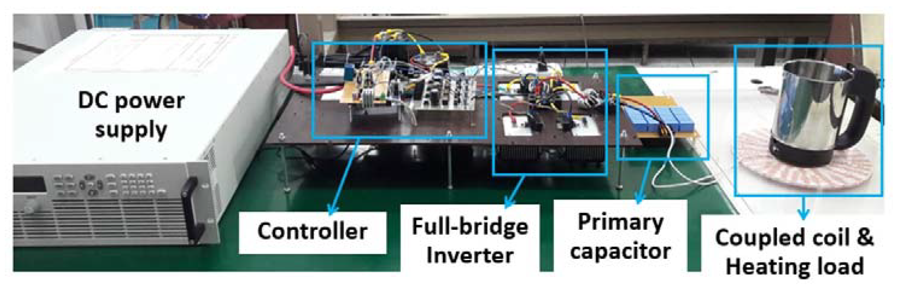
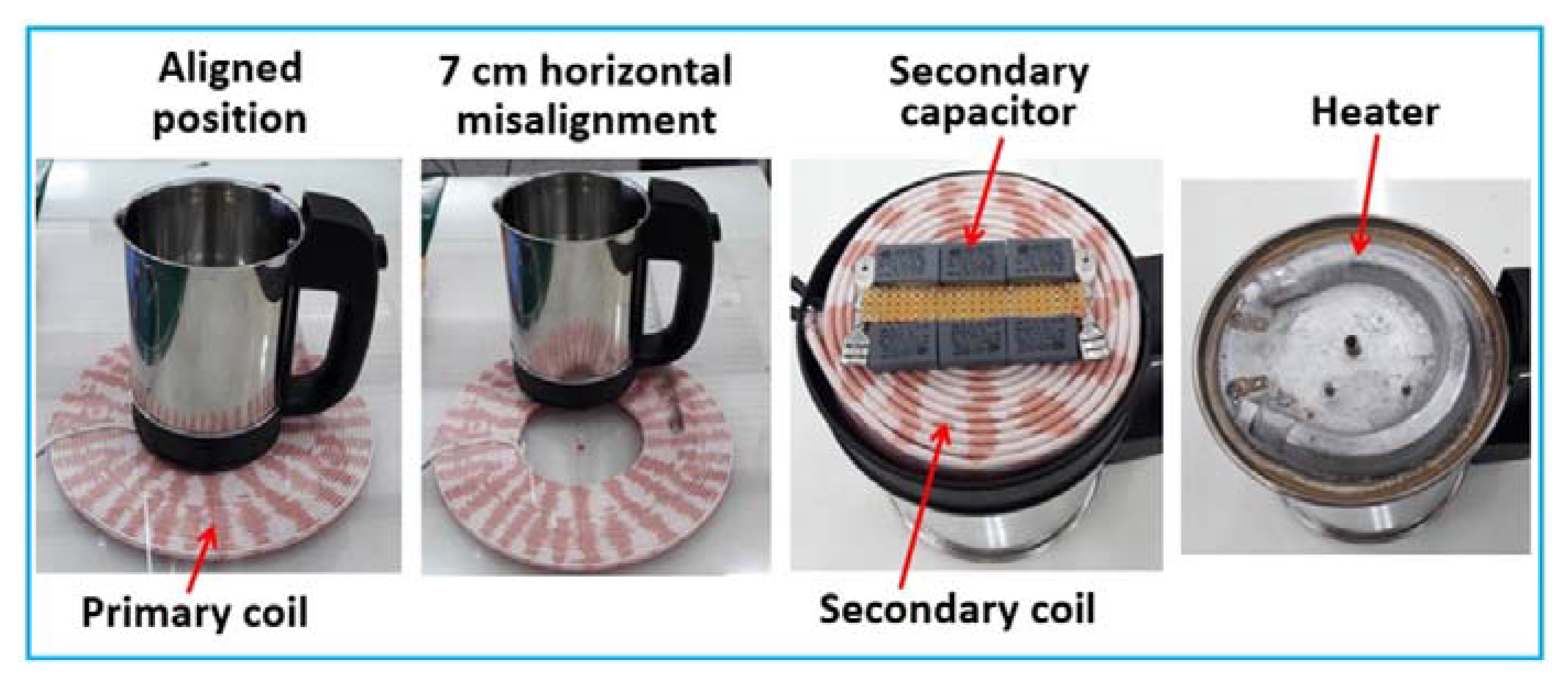
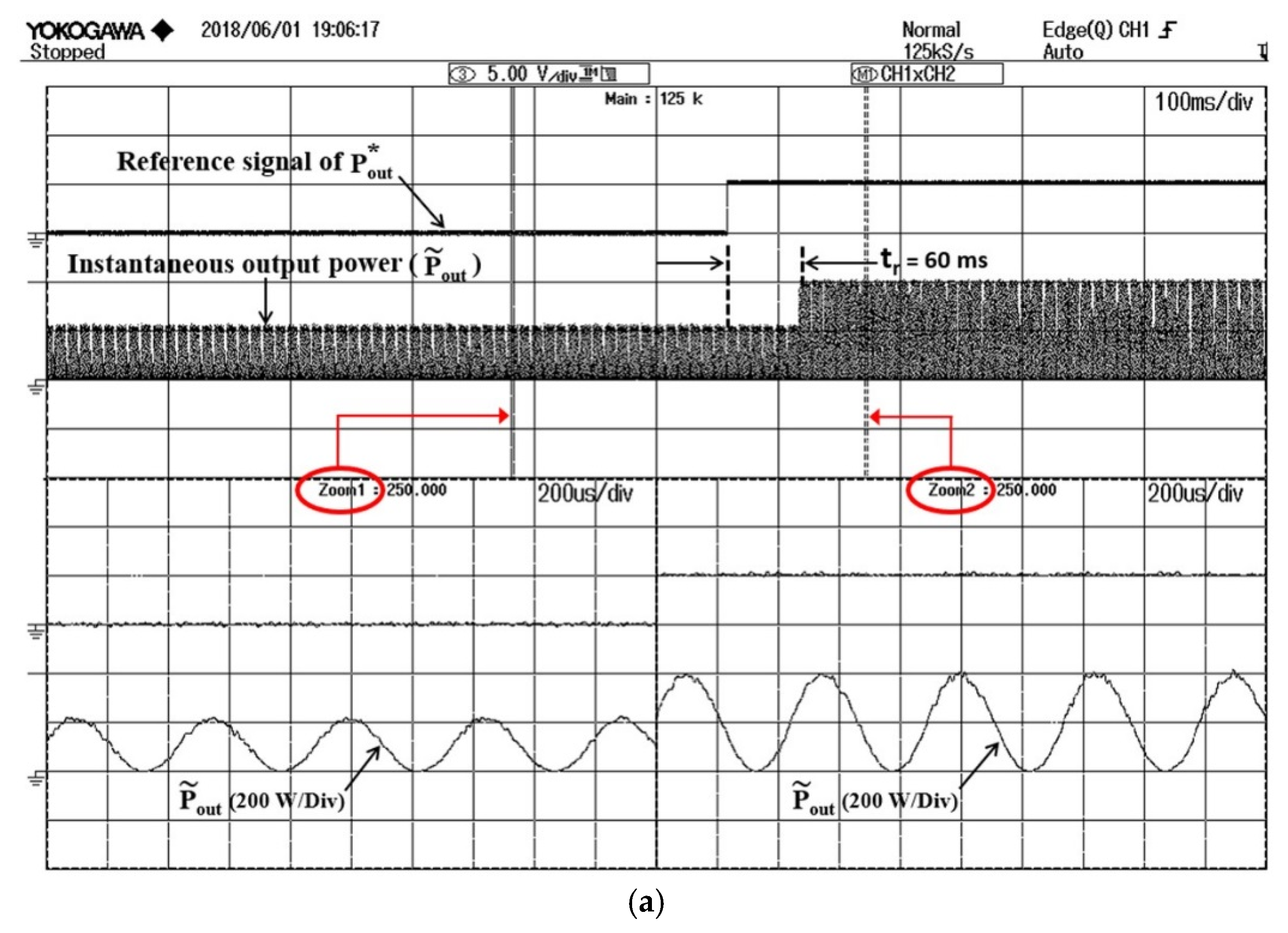
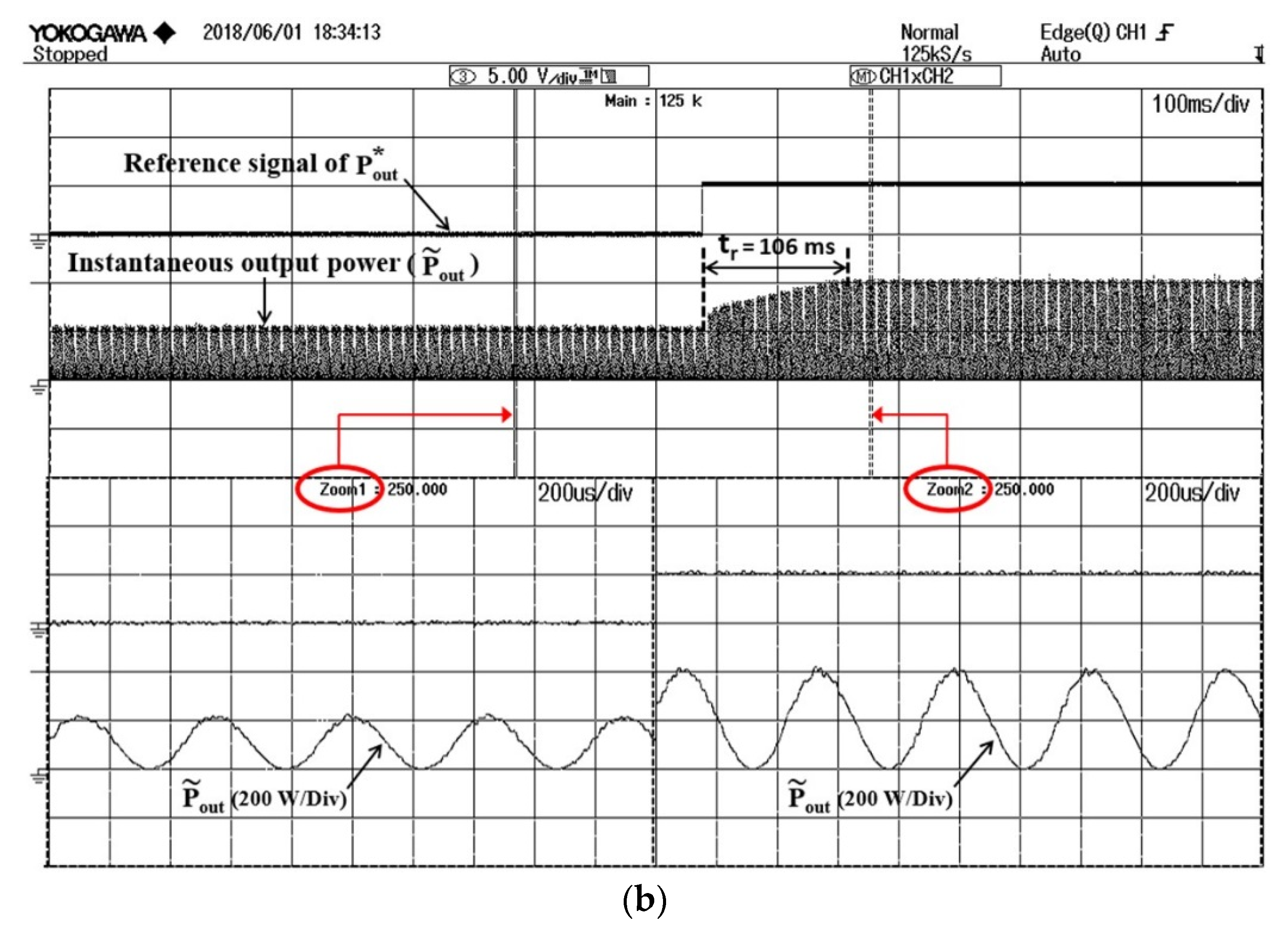
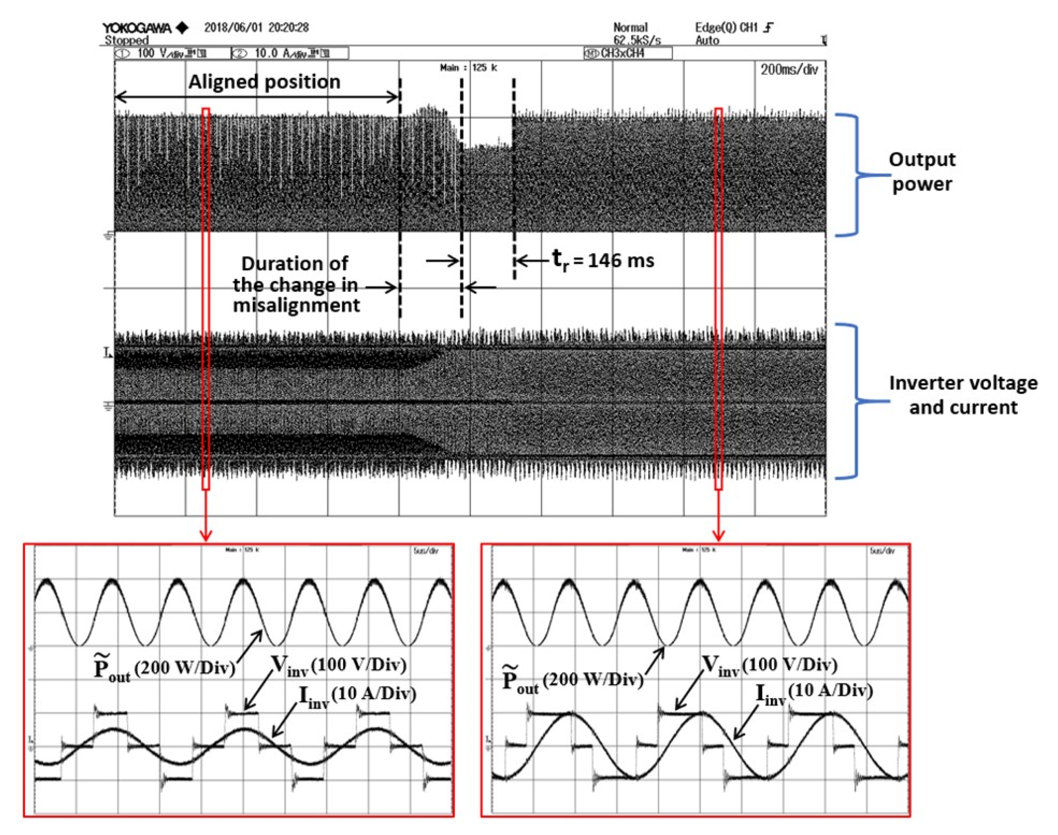
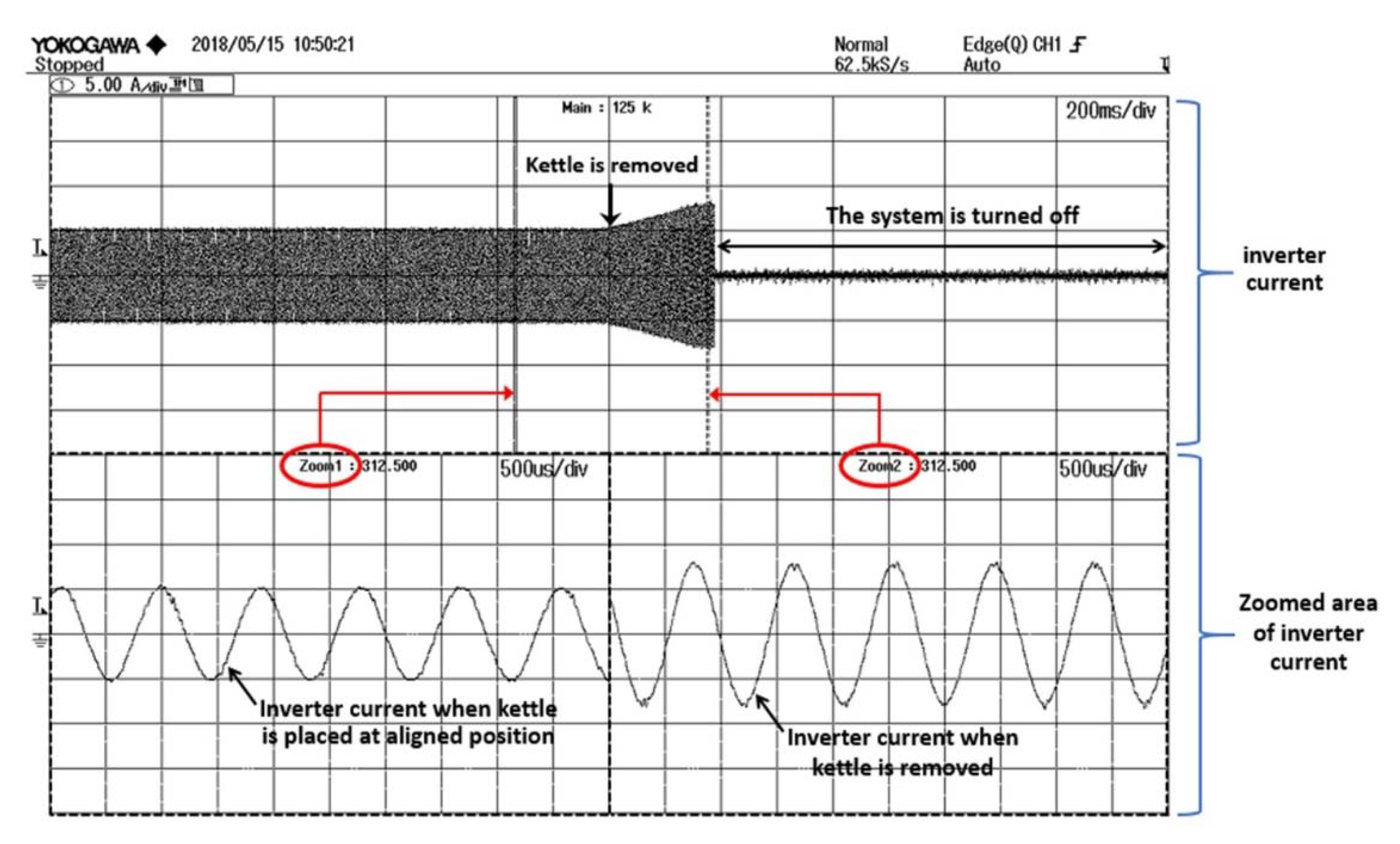
4. Experimental Results

To investigate the performance of the proposed controller, a prototype of a wireless power transfer system for a kitchen appliance, as shown in Figure 8, is created using parameters in Table 1. A 200 W kettle is the heating load. As shown in Figure 9, the primary coil is a two-layer spiral coil. Each layer contains 21 turns of litz wire. The inner and outer diameters are 9 and 22 cm, respectively. The secondary coil is a four-layer spiral coil with six turns in each layer, located at the bottom of the kettle. The inner and outer diameters of the secondary coil are 2.5 and 9 cm, respectively. The primary coil is placed in a fixed position, whereas the secondary coil can be laterally moved in a designated area of 7 cm from the center of the primary coil. The free-positioning feature causes a horizontal misalignment for which the mutual inductance is varied. The vertical distance between the coupled coils is fixed at 1 cm, representing the thickness of a stove top. The input DC voltage is 100 V. The switching frequency of the inverter circuit is fixed at the secondary resonant frequency of 63.62 kHz.
The output power step responses are shown in Figure 10a,b for the proposed MPC and conventional PI control, respectively. The output reference, P o u t * , is stepped from 100 to 200 W. The response times, t r , of the instantaneous power are 60 ms and 106 ms for the proposed MPC and PI control, respectively.
The misalignment issue is experimentally investigated, as shown in Figure 11. The kettle is initially placed at the aligned position, with the output power set to 200 W. Then, it is horizontally moved by 7 cm from the center of the primary coil. This causes a variation in the output power of the kettle. With the proposed controller, the output power is restored to the original value of 200 W within 146 ms. This is achieved by automatically increasing the duty cycle of the inverter voltage.
Figure 12 shows experimental results of the system protection. At first, the kettle is placed at the aligned position. It is then removed from the primary coil. The inverter current is substantially increased due to the reduction of the reflected impedance, as mentioned earlier. After the absence of the kettle is detected, the system is turned off to avoid damage to the system.
For different horizontal misalignments, the mutual inductance and system efficiency at the same output power of 200 W are measured, as shown in Figure 13. The mutual inductance is rather constant when the horizontal misalignment of the kettle is in the range of 0–3 cm, due to the characteristic of asymmetry between the coupled coils. Beyond 3 cm, the mutual inductance is decreasing along with the misalignment. The maximum efficiency is 91%. It is reduced to 76.9% at 7 cm horizontal misalignment. This is due to the increased primary current, as observed in Figure 11, which accumulates the loss in the primary coil.

5. Conclusions

A novel output power control of the WPT system is presented in this paper. It is based on the model predictive strategy. It utilizes the system’s mathematical model to predict the feasible output power. The optimal duty cycle for a desired output power is obtained through the minimization of the objective function, which is simple and easy to implement, with no need for gain tuning. The proposed controller is implemented on the primary side, without any measurement and communication devices on the secondary. This reduces the cost, size, and complexity of the WPT system. Furthermore, the on-line load resistance and mutual inductance identification technique is introduced. It is based on reflected impedance knowledge, where the identification formulas are derived from the reflected resistance and reactance. The proposed identification method only needs the inverter current. Experimental results have confirmed that the proposed controller has a faster response than conventional PI control. The output power can be regulated at a targeted value through the designated misalignment of 7 cm (i.e., 63.64% of the coil’s outer radius). The system efficiency ranges from 76.9 to 91%, depending on the horizontal misalignment. The proposed controller is simple, low-cost, and can be adopted in any other WPT applications.

Author Contributions

S.N. (Supapong Nutwong) proposed the main idea, performed the experiment and wrote the manuscript. A.S., S.N. (Sumate Naetiladdanon) and E.M. provided key suggestions and improved the manuscript.

Funding

This research was supported by the Petchra Pra Jom Klao Doctoral Scholarship, King Mongkut’s University of Technology Thonburi.

Conflicts of Interest

The authors declare no conflict of interest.

References

  1. Hui, S.Y.R.; Zhong, W.; Lee, C.K. A Critical Review of Recent Progress in Mid-Range Wireless Power Transfer. IEEE Trans. Power Electron. 2014, 29, 4500–4511. [Google Scholar] [CrossRef] [Green Version]
  2. Musavi, F.; Eberle, W. Overview of wireless power transfer technologies for electric vehicle battery charging. IET Power Electron. 2014, 7, 60–66. [Google Scholar] [CrossRef]
  3. Dai, J.; Ludois, D.C. A Survey of Wireless Power Transfer and a Critical Comparison of Inductive and Capacitive Coupling for Small Gap Applications. IEEE Trans. Power Electron. 2015, 30, 6017–6029. [Google Scholar] [CrossRef]
  4. Ahn, D.; Hong, S. Wireless Power Transmission with Self-Regulated Output Voltage for Biomedical Implant. IEEE Trans. Ind. Electron. 2014, 61, 2225–2235. [Google Scholar] [CrossRef]
  5. Roshan, Y.M.; Park, E.J. Design approach for a wireless power transfer system for wristband wearable devices. IET Power Electron. 2017, 10, 931–937. [Google Scholar] [CrossRef]
  6. Falkenstein, E.; Costinett, D.; Costinett, R.; Popovic, Z. Far-Field RF-Powered Variable Duty Cycle Wireless Sensor Platform. IEEE Trans. Circuits Syst. II 2011, 58, 822–826. [Google Scholar] [CrossRef]
  7. Lu, Y.; Ma, D.B. Wireless Power Transfer System Architectures for Portable or Implantable Applications. Energies 2016, 9, 1087. [Google Scholar] [CrossRef]
  8. Liu, H.; Huang, X.; Tan, L.; Guo, J.; Wang, W.; Yan, C.; Xu, C. Dynamic Wireless Charging for Inspection Robots Based on Decentralized Energy Pickup Structure. IEEE Trans. Ind. Informat. 2018, 14, 1786–1797. [Google Scholar] [CrossRef]
  9. Wang, Z.; Wei, X.; Dai, H. Design and Control of a 3 kW Wireless Power Transfer System for Electric Vehicles. Energies 2015, 9, 1–18. [Google Scholar] [CrossRef]
  10. Lee, S.H.; Kim, J.H.; Lee, J.H. Development of a 60 kHz, 180 kW, Over 85% Efficiency Inductive Power Transfer System for a Tram. Energies 2016, 9, 1075. [Google Scholar] [CrossRef]
  11. Kim, J.W.; Son, H.C.; Kim, D.H.; Park, Y.J. Optimal Design of a Wireless Power Transfer System with Multiple Self-Resonators for an LED TV. IEEE Trans. Consum. Electron. 2012, 58, 775–780. [Google Scholar] [CrossRef]
  12. Wang, Z.H.; Li, Y.P.; Sun, Y.; Tang, C.S.; Lv, X. Load Detection Model of Voltage-Fed Inductive Power Transfer System. IEEE Trans. Power Electron. 2013, 28, 5233–5243. [Google Scholar] [CrossRef]
  13. James, J.E.; Robertson, D.J.; Covic, G.A. Improved AC Pickups for IPT Systems. IEEE Trans. Power Electron. 2014, 29, 6361–6374. [Google Scholar] [CrossRef]
  14. Tsiropoulou, E.E.; Mitis, G.; Papavassiliou, S. Interest-aware energy collection & resource management in machine to machine communications. Ad Hoc Netw. 2018, 68, 48–57. [Google Scholar] [CrossRef]
  15. Kim, T.H.; Yun, G.H.; Lee, W.Y.; Yook, J.G. Asymmetric Coil Structures for Highly Efficient Wireless Power Transfer Systems. IEEE Trans. Microw. Theory Tech. 2018, 1–9. [Google Scholar] [CrossRef]
  16. Vamvakas, P.; Tsiropoulou, E.E.; Vomvas, M.; Papavassiliou, S. Adaptive Power Management in Wireless Powered Communication Networks: A User-Centric Approach. In Proceedings of the IEEE 38th Sarnoff Symposium, Newark, NJ, USA, 18–20 September 2017; pp. 1–6. [Google Scholar]
  17. Kim, T.H.; Yoon, S.; Yook, J.G.; Yun, G.H.; Lee, W.Y. Evaluation of Power Transfer Efficiency with Ferrite Sheets in WPT System. In Proceedings of the IEEE Wireless Power Transfer Conference (WPTC), Taipei, Taiwan, 10–12 May 2017; pp. 1–4. [Google Scholar]
  18. Costanzo, A.; Masotti, D. Energizing 5G: Near- and Far-Field Wireless Energy and Data Trantransfer as an Enabling Technology for the 5G IoT. IEEE Microw. Mag. 2017, 18, 125–136. [Google Scholar] [CrossRef]
  19. Zhong, W.X.; Liu, X.; Hui, S.Y.R. A Novel Single-Layer Winding Array and Receiver Coil Structure for Contactless Battery Charging Systems with Free-Positioning and Localized Charging Features. IEEE Trans. Ind. Electron. 2011, 58, 4136–4144. [Google Scholar] [CrossRef] [Green Version]
  20. Yeo, T.D.; Kim, D.H.; Chae, S.C.; Khang, S.T.; Yu, J.W. Design of Free-Positioning Wireless Power Charging System for AAA Rechargeable Battery. In Proceedings of the 46th European Microwave Conference, London, UK, 4–6 October 2016; pp. 759–762. [Google Scholar]
  21. Madawala, U.K.; Thrimawithana, D.J. New technique for inductive power transfer using a single controller. IET Power Electron. 2012, 5, 248–256. [Google Scholar] [CrossRef]
  22. Chan, T.S.; Chen, C.L. A Primary Side Control Method for Wireless Energy Transmission System. IEEE Trans. Circuits Syst. 2012, 59, 1805–1814. [Google Scholar] [CrossRef]
  23. Yin, J.; Lin, D.; Lee, C.K.; Hui, S.Y.R. A Systematic Approach for Load Monitoring and Power Control in Wireless Power Transfer Systems without Any Direct Output Measurement. IEEE Trans. Power Electron. 2015, 30, 1657–1667. [Google Scholar] [CrossRef]
  24. Cai, H.; Shi, L.; Li, Y. Harmonic-Based Phase-Shifted Control of Inductively Coupled Power Transfer. IEEE Trans. Power Electron. 2014, 29, 594–602. [Google Scholar] [CrossRef]
  25. Matsumoto, H.; Neba, Y.; Asahara, H. Switched Compensator for Contactless Power Transfer Systems. IEEE Trans. Power Electron. 2015, 30, 6120–6129. [Google Scholar] [CrossRef]
  26. Nutwong, S.; Sangswang, A.; Naetiladdanon, S. Output voltage control of the SP topology IPT system using a primary side controller. In Proceedings of the IEEE International Conference on Electrical Engineering/Electronics, Computer, Telecommunications and Information Technology, Chiang Mai, Thailand, 28 June–1 July 2016; pp. 1–5. [Google Scholar]
  27. Aditya, K.; Williamson, S. Linearization and Control of Series-Series Compensated Inductive Power Transfer System Based on Extended Describing Function Concept. Energies 2016, 9, 962. [Google Scholar] [CrossRef]
  28. Su, Y.G.; Zhang, H.Y.; Wang, Z.H.; Hu, A.P.; Chen, L.; Sun, Y. Steady-State Load Identification Method of Inductive Power Transfer System Based on Switching Capacitors. IEEE Trans. Power Electron. 2015, 30, 6349–6355. [Google Scholar] [CrossRef]
  29. Chow, J.P.W.; Chung, H.S.H.; Cheng, C.S. Use of Transmitter-Side Electrical Information to Estimate Mutual Inductance and Regulate Receiver-Side Power in Wireless Inductive Link. IEEE Trans. Power Electron. 2016, 31, 6079–6091. [Google Scholar] [CrossRef]
  30. Yin, J.; Lin, D.; Parisini, T.; Hui, S.Y.R. Front-End Monitoring of the Mutual Inductance and Load Resistance in a Series–Series Compensated Wireless Power Transfer System. IEEE Trans. Power Electron. 2016, 31, 7339–7352. [Google Scholar] [CrossRef]
  31. Darba, A.; Belie, F.D.; D’haese, P.; Melkebeek, J.A. Improved Dynamic Behavior in BLDC Drives Using Model Predictive Speed and Current Control. IEEE Trans. Ind. Electron. 2016, 63, 728–740. [Google Scholar] [CrossRef]
  32. Mora, A.; Orellana, A.; Juliet, J.; Cárdenas, R. Model Predictive Torque Control for Torque Ripple Compensation in Variable-Speed PMSMs. IEEE Trans. Ind. Electron. 2016, 63, 4584–4592. [Google Scholar] [CrossRef]
  33. Hu, J.; Zhu, J.; Dorrell, D.G. Model Predictive Control of Grid-Connected Inverters for PV Systems with Flexible Power Regulation and Switching Frequency Reduction. IEEE Trans. Ind. Appl. 2015, 51, 587–594. [Google Scholar] [CrossRef]
  34. Scoltock, J.; Geyer, T.; Madawala, U.K. Model Predictive Direct Power Control for Grid-Connected NPC Converters. IEEE Trans. Ind. Electron. 2015, 62, 5319–5328. [Google Scholar] [CrossRef]
  35. Kranprakon, P.; Sangswang, A.; Naetiladdanon, S.; Mujjalinwimut, E. A Model Predictive Control of an LLC Resonant Inverter for Tin Melting Application. In Proceedings of the 43rd Annual Conference of the IEEE Industrial Electronics Society (IECON), Beijing, China, 29 October–1 November 2017; pp. 3773–3778. [Google Scholar]
  36. Niyomthai, S.; Sangswang, A.; Naetiladdanon, S.; Mujjalinwimut, E. A Predictive Control of Class E Resonant Inverter for Ultrasonic Cleaners. In Proceedings of the 43rd Annual Conference of the IEEE Industrial Electronics Society (IECON), Beijing, China, 29 October–1 November 2017; pp. 6319–6324. [Google Scholar]
  37. Wang, C.S.; Stielau, O.H.; Covic, G.A. Design Considerations for a Contactless Electric Vehicle Battery Charger. IEEE Trans. Ind. Electron. 2005, 52, 1308–1314. [Google Scholar] [CrossRef]
Figure 1. The proposed wireless power transfer (WPT) system.
Energies 11 01671 g001
Figure 2. Commonly used model of WPT system: (a) Mutual inductance coupling model of the series-parallel (SP) topology WPT system; (b) source transformation in the secondary circuit; (c) reflected impedance referred to primary circuit.
Energies 11 01671 g002
Figure 3. The plot of reflected reactance against load resistance for different mutual inductance.
Energies 11 01671 g003
Figure 4. Frequency response of the system efficiency.
Energies 11 01671 g004
Figure 5. Gate signals and the corresponding waveform of the full-bridge inverter with phase-shift control.
Energies 11 01671 g005
Figure 6. The proposed system.
Energies 11 01671 g006
Figure 7. Program flowchart of the microcontroller.
Energies 11 01671 g007
Figure 8. Experimental setup.
Energies 11 01671 g008
Figure 9. Free-positioning kettle setup.
Energies 11 01671 g009
Figure 10. Experimental results of the output power step response: (a) Proposed model predictive control (MPC); (b) PI control.
Energies 11 01671 g010aEnergies 11 01671 g010b
Figure 11. Experimental results of the output power regulation when kettle is moved 7 cm from aligned position.
Energies 11 01671 g011
Figure 12. Experimental results of the system protection when the kettle is removed.
Energies 11 01671 g012
Figure 13. Experimental measurement of system efficiency and mutual inductance at different horizontal misalignments.
Energies 11 01671 g013
Table 1. Designed circuit parameters.
ParametersValue
L1290.1 µH
L272.14 µH
M (at aligned position)31.37 µH
M (at 7 cm horizontal misalignment)19.33 µH
C122.51 nF
C286.72 nF
R10.6 Ω
R20.56 Ω
RL90.2 Ω
f0263.62 kHz

