Article

The Influence of LED Lighting Sources on the Nature of Power Factor

1
Departments of Electric Drivers and Energy Conversions, Faculty of Electrical and Control Engineering, Gdansk University of Technology, ul. G. Narutowicza 11/12, 80-288 Gdansk, Poland
2
Departments of Metrology and Optoelectronics, Faculty of Electronics, Telecommunications and Informatics, Gdansk University of Technology, ul. G. Narutowicza 11/12, 80-288 Gdansk, Poland
*
Author to whom correspondence should be addressed.
Energies 2018, 11(6), 1479; https://doi.org/10.3390/en11061479
Submission received: 25 April 2018 / Revised: 2 June 2018 / Accepted: 4 June 2018 / Published: 6 June 2018

Abstract

:
This article presents measurements of electric power absorbed by a newly built facility for office and scientific research activities. These measurements highlighted the need for compensation of capacitive reactive power—not predicted by the designer—due to the vast use of LED lighting in the facility. The article also describes a reactive power compensation system, designed on the basis of the above-mentioned measurements, and the introduced control and measurement system that enables on-site monitoring and online analysis of consumed energy and power. The research was carried out using popular LED lighting sources available on the local market (Poland). Basic electrical parameters of the locally available LEDs were measured as a function of the changes in harmonic levels occurring in the supply voltage. The test illustrated that samples were characterized by a very low power factor, which decreased as the level of harmonic disturbances increased. On the basis of the measurements, the authors suggest that obligatory requirements should be introduced in regard to the minimum power factor at the level of 0.9 for popular LED lighting sources (below 25 W).

1. Introduction

The performance of various power and electronic systems in conditions where harmonic voltages and currents appear has been an important aspect of various research and functional works for a long time. Such performance involves minimizing the adverse effects of higher harmonics on various elements of the power infrastructure. The occurrence of various electromagnetic disturbances protruding in the supplied electric energy is associated mainly with the constantly developing methods of processing the energy into other useful forms. Both electricity suppliers and consumers insist that the provided energy is of the appropriate quality. The quality of electric energy is usually determined on the basis of conditions related to the adopted standards, as well as measurements of accepted descriptive parameters and legal requirements. In addition, energy suppliers, upon concluded contracts, often limit the possibility of using reactive power from the electrical power system which, at the same time, introduces a significant financial burden for the energy recipient who does not meet the adopted requirements. Under the presented conditions, the energy supplier has included in the contract the stipulation of not collecting the capacitive reactive power from the network. Nonetheless, energy recipients often employ systems of continuous monitoring and compensation of the consumed reactive power. As a rule, such systems are typically assembled in newly built or modernized facilities. Currently, it is emphasized that the facilities should be characterized by low energy demands for their own needs. The newly designed facilities are, at the initial stage of being put into operation, already adapted to the installation of intelligent control steering systems that ensure the optimization of control, such as lighting sources and air conditioning. In most cases, users of such facilities are obliged to use devices, characterized by specific parameters that meet certain requirements that are recommended by designers. Such an approach should result, on one hand, in limiting operating costs. On the other hand, it should also reduce the risk resulting from, among others, introducing additional disturbances to the mains. However, on these facilities appears also a significant amount of the cheapest LED light sources that may significantly affect the introduced disturbances and the nature of the power factor (PF). The PF coefficient presented in this article allows one to determine, in a concise way, the impact of all receivers working on the supply network. On the other hand, the fundamental power factor determines the demand for reactive power, which, in the case of LED receivers, is of capacitive nature. For facilities equipped with a large number of LED light sources with unit powers lower than 25 W, there occurs the accumulation of the following phenomena: an increase in the number of current and voltage harmonics and the generation of capacitive reactive power. A similar approach is presented, among others, in papers [1,2,3]. It is commonly known that a high value of disturbances may cause various power devices (residual current devices, control devices, signal transmission devices) to operate incorrectly [3,4]. Frequently, harmonics occurring from various nonlinear electric energy receivers may lead to various damages. Their occurrence usually results in the overheating of circuits with magnetic cores or, in critical situations, may even lead to an overload of the capacitor battery used in inductive reactive power compensation systems [5,6]. However, these are usually single and rare cases when supervision of disturbances occurring in a given facility is not being carried out properly. The paper presents results of measurements and tests carried out on a newly built facility, which, to large extent, uses energy-saving LED lighting sources. Vast introduction of LED lighting, in addition to the expected further decrease in demand for consumed power in relation to used luminaries with gas-discharge light sources (approximately 30%) [7,8], also leads to deterioration of the power factor and an increase in the capacitive reactive power. Basic information on their application can be found inter alia in [9,10,11,12]. Additionally, a number of publications [13,14] contain information on the safety of the use of lighting based on LED sources and emerging hazards associated with the use of such lighting. Though, aspects related to spectral efficiency and its safety are not addressed in this article.
The hypotheses for introducing LED lighting sources are assumed and the systems should be highly efficient. However, apart from introducing additional harmonics caused by non-sinusoidal currents, there is often a change in the nature of the consumed reactive power, which may result in a negative impact on the network [15]. The nature of these interactions was also presented in a paper [12], which suggested the possibility of occurrence of indicated problems related to the impact of lighting systems on the power factor.
The conclusion presented above was formulated on the basis of measurements carried out in a newly opened facility and measurements of selected LED lighting sources available on the market, during which a low power factor was found. The measurements were performed at the request of the facility user, who bore additional costs related to the consumption of reactive capacitive energy (over 42% of the costs on the invoice accounted for the cost of reactive capacitive energy). Yet, in the design phase, it was assumed that the facility should consume it at the minimum level. The measurement results are presented with the consent of the person who ordered them—“Research and Development Center for Renewable Energy Sources”. The work presents applied measurement systems for on-site testing and for LED lighting source tests. The implemented system for monitoring and compensation of reactive power, which allows the quality of selected electrical energy parameters on the facility’s network to be determined, is also described.
2. Objects of the Research and Applied Measurement Systems

2.1. Building Facilities

Measurements were taken on a newly opened facility consisting of two floors that are intended for offices and research laboratories of low intensity. The total usable floor area of the facility is ~1000 m2, and approximately 30 people were working in the building during the research. The installed equipment consists mainly of distributed loads in the form of computers (in offices). There has been no specialized equipment installed at the facility that could affect the power consumption. The total estimated power requested for the facility, including working air-conditioning equipment, was set at ~35 kW (maximum ordered power was 40 kW). The facility has its own 250 kVA transformer substation. The main lighting is realized by means of fluorescent lighting fixtures supported by a large number of cheap lighting fittings adapted to the installation of popular LED lighting sources. The lighting mainly used luminaries cooperating with LED lighting (over 80% of all fittings on the site). The tests presented below have been carried out on some of the LED lighting sources identified on the site.
Loads installed in the facility consist mainly of lighting installations and air conditioning, which was not working during the period this research was conducted. There are no industrial loads (engines and high-power electricity conversion equipment) in the facility. The measurements were carried out with a PQ-BOX 200 meter from AEberle, which was presented in detail in [16]. The preliminary measurements were carried out in the period of ~4 h during the winter-spring turn. All measurements were taken when the facility was functioning normally (no modifications were made to its operation).

2.2. Research of Selected LED Lighting Sources

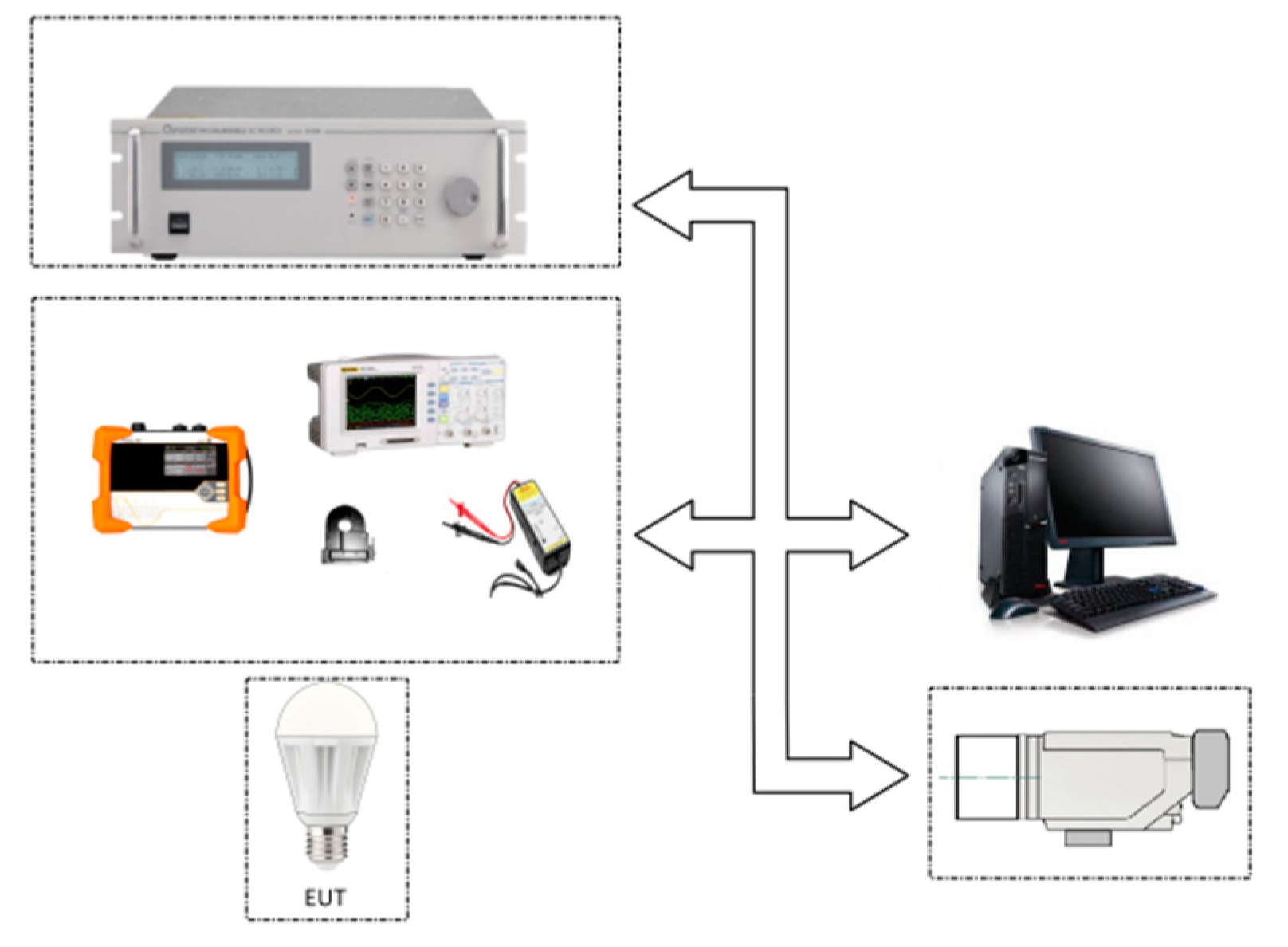
Research was also carried out on LED lighting sources used in the facility in an isolated environment while energized with distorted voltages. The tested LED lighting sources are classified as generally available on the local market (Poland). In that case, electrical parameters and, additionally, temperature increments were monitored with the use of thermographic measurements. For testing LED lighting sources in an isolated power system, the Chroma (model 61503) power supply [17] was used. Tests were carried out with the use of the measurement setup shown in Figure 1. The measurement system included: R&S RT-ZD01 voltage probe, ALCL-40D current probe, RIGOL 1102D oscilloscope, PQ-BOX 200 meter, VIGOcam v.50 thermal imaging camera with reference field.
Commonly available on the local market, LED lighting sources with declared power levels of 10–14 W were selected for tests in the isolated environment. Measurements were carried out on new LED sources that had previously worked for 100 h at a power supply with a non-distorted voltage of 230 V. Thermal imaging tests were carried out for a period of at least 120 min, which guaranteed the temperature stability of the tested facilities at an ambient temperature of 25 ± 5 °C. Table 1 lists the basic technical data declared by manufacturers on the packaging or housing of the tested LED lighting sources.
Table 2 illustrates the values of individual tests of the lighting source. Test T1 was used as the reference level in which the LED lighting source was supplied with voltage without harmonic disturbances. For Tests T2 and T4, the values of harmonic disturbance levels were selected on the basis of observations. In Test T4, the voltage of components 3 and 7 was shifted by 90° in relation to the basic component, resulting in the sharpening of the waveform. The level of exposure values for Test T3 was chosen on the basis of the maximum permitted harmonic disturbances introduced into a low-voltage network, as per EN 50160:2010 + A1:2015, to harmonics at the level of 13. All measurements were carried out at the basic component level (50 Hz) at 230 V. The values of all harmonics ranging from 14th to 40th harmonic were 0%. The values of introduced harmonic disturbances are given in percentage correlation to the value of the basic component.
Temperature measurements of the tested LED light sources were carried out by recording thermograms with the use of a thermal imaging camera (VIGOcam v.50) and a reference source with a known emissivity coefficient (ε) placed in the field of the camera view. This approach allowed the influence of the variability of the emissivity coefficient (ε) of the tested facility to be minimized, which is necessary to determine the temperature of the object. The average temperature increments (ΔTAV) of the observed surface reported in this paper were determined in correlation to the reference source. Measurements of average temperature increments (ΔTAV) of LED lighting sources were carried out in order to verify the behavior of this type of receiver, in case of it being powered by distorted voltage.

3. Measurement Results

All power measurements presented in the paper refer to the parameters determined in accordance with recommendations of the electrical energy supplier and take into account the recommendations contained in IEE 1459: 2010 [18].

3.1. Measurements of the Facility

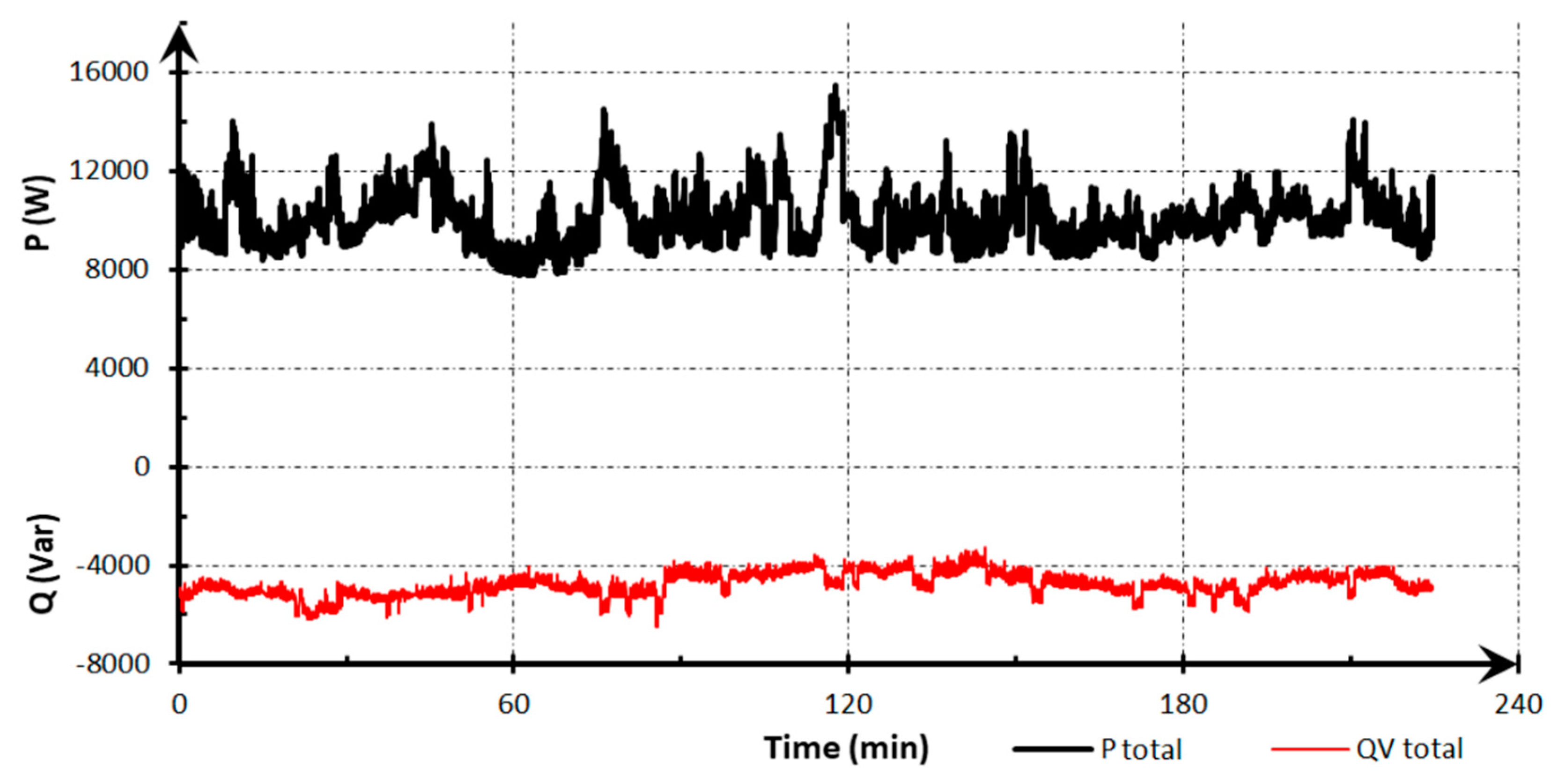
Table 3 presents selected results of measurements carried out in the winter-spring period during normal operation in a period of about 4 h.
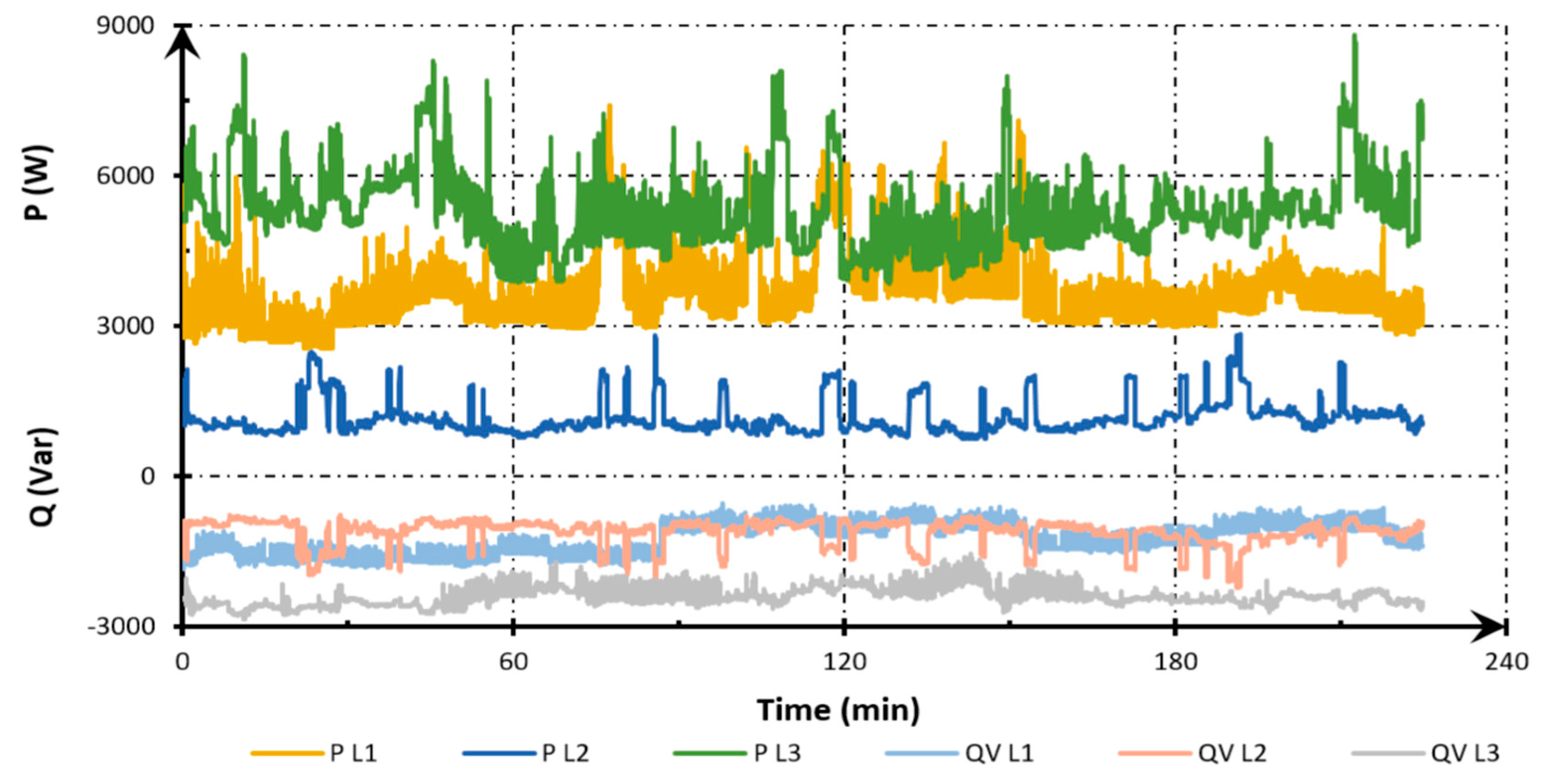
Figure 2 shows the variability of active and reactive total power in the monitored period. Figure 3 shows changes in active and reactive power on individual phases L1, L2, L3 during the measurements.
Table 4 shows the consumption of active and reactive power for the monitored phases L1, L2, L3.
Table 5 presents the measured values of the fundamental power factor (PFH1), average total harmonic distortion in the voltage (THDU) for individual phases and the determined power factor.
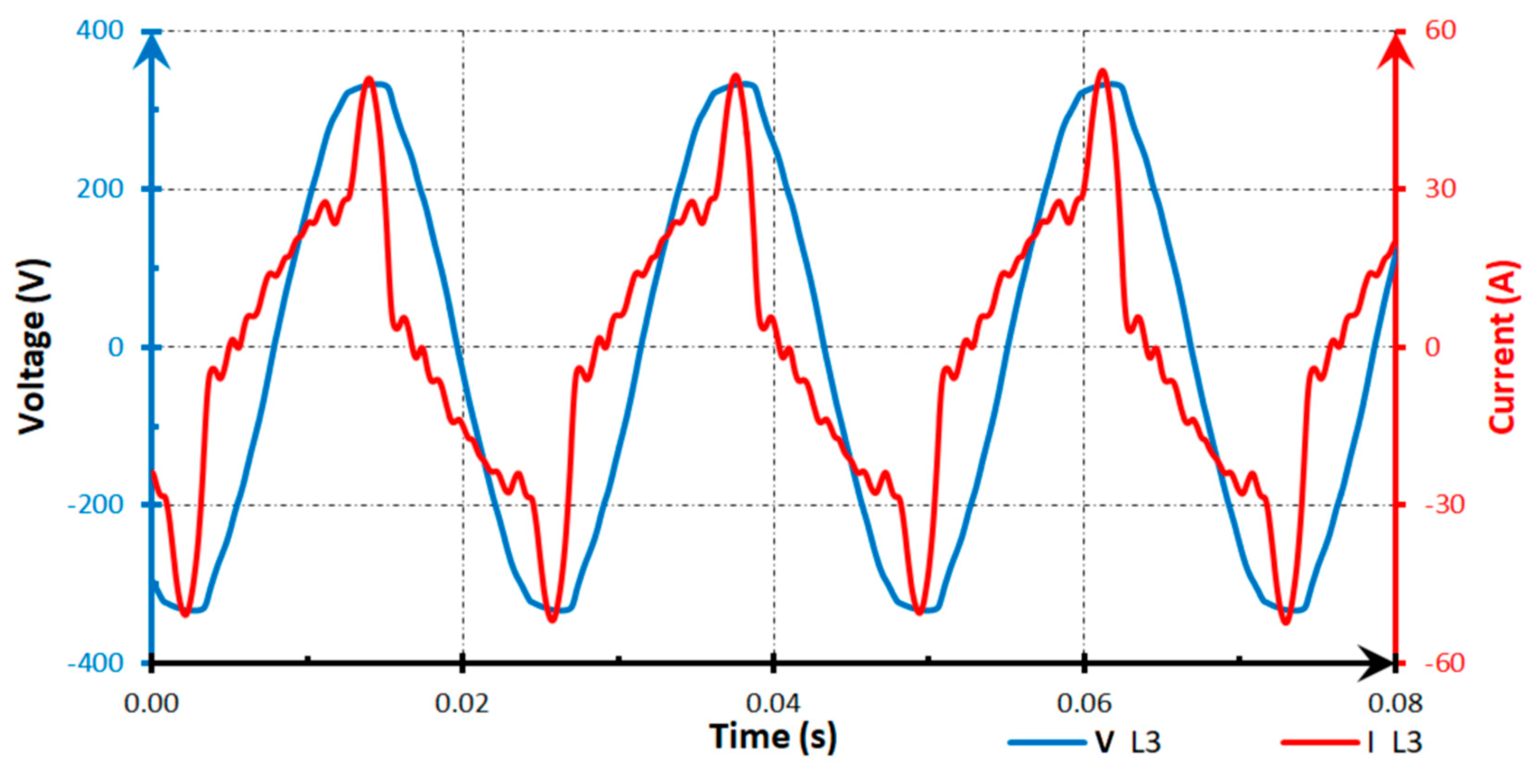
Figure 4 presents a typical course of voltage and power in the L3 phase, in which the highest active power loads were recorded.
The measurements presented above were the basis for the selection of current-compensated chokes.

3.2. Measurements of Selected LED Lighting Sources

Table 6 lists measurement results of basic electrical parameters obtained for the tested LED lighting sources.
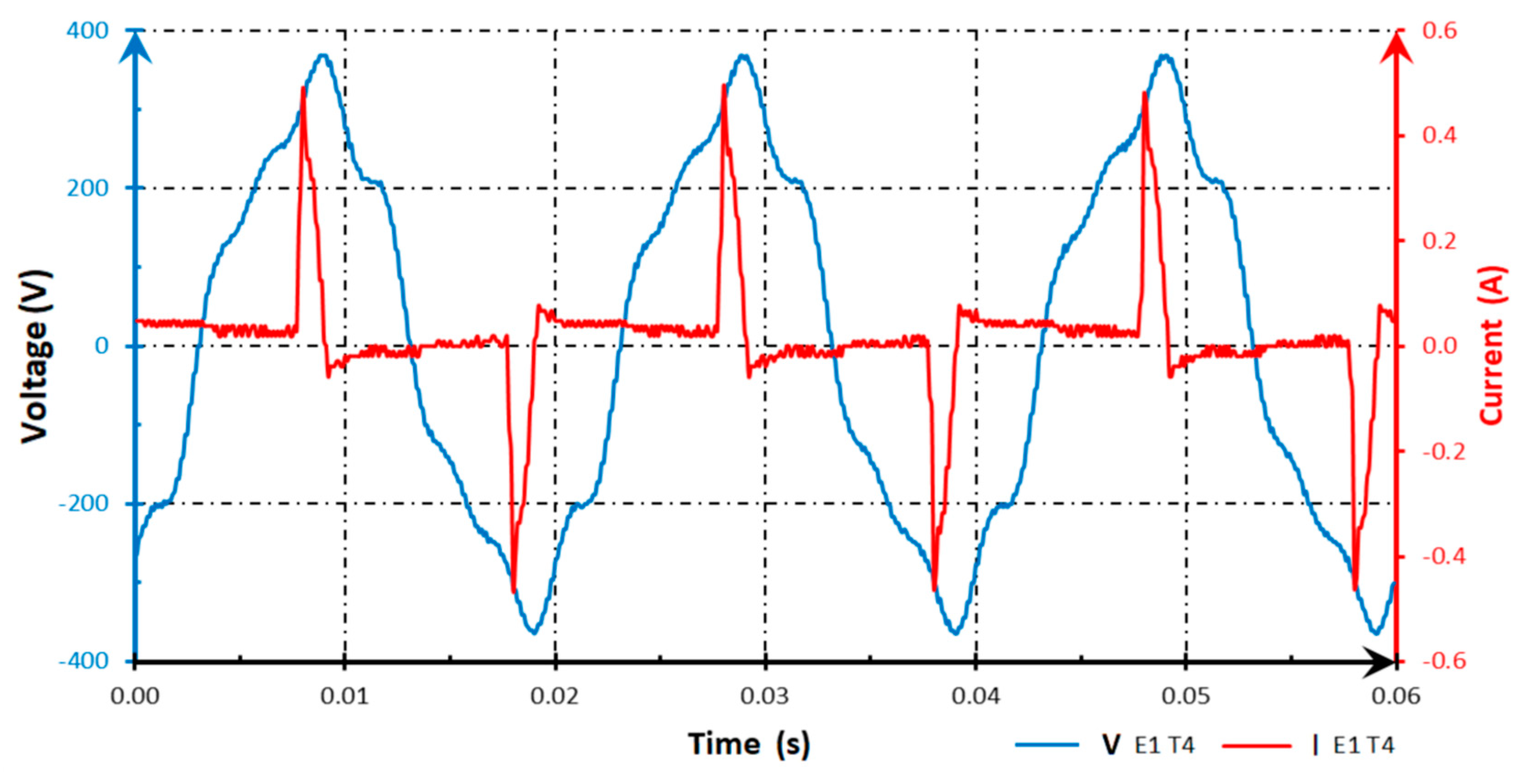
Figure 5 presents a typical course of voltages and currents during the study of the E1 lighting source while testing with levels for Test T4, which can be considered typical for all tested sources.
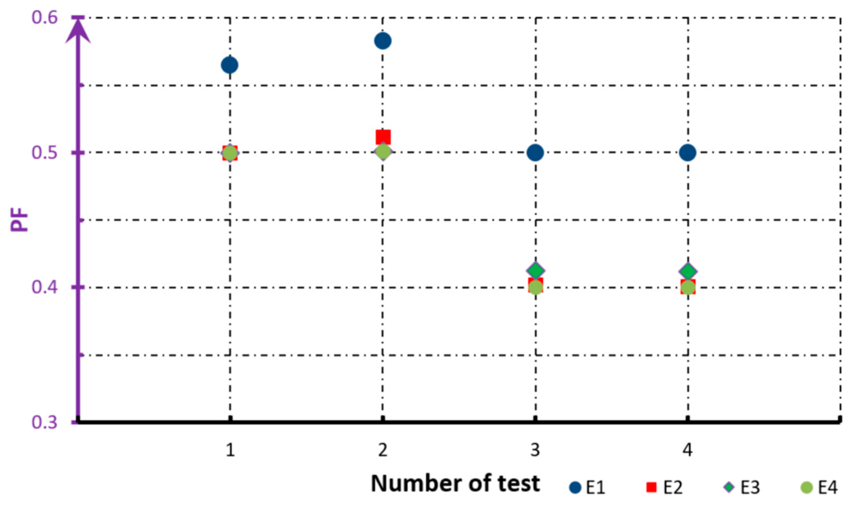
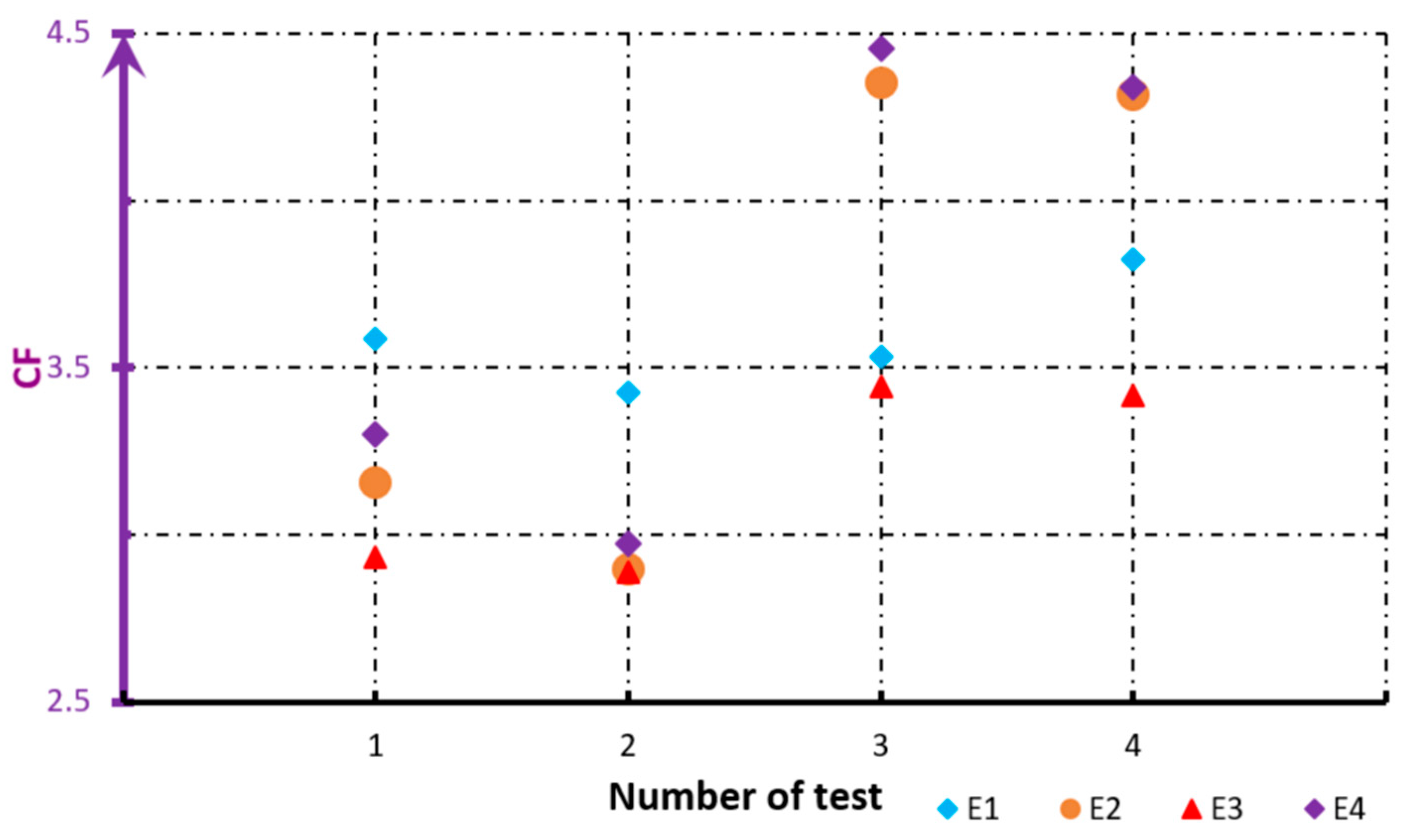
Simultaneously, in Figure 6 and Figure 7, results of changes in power factor (PF) and crest factor (CF) in the function of tests are presented.
Measurement results of average temperature increments (∆TAV) are presented in Table 7. According to assumptions, tested LED sources are less sensitive to changes in harmonic content in the supply voltage, as they are not equipped with magnetic circuits.

4. The Applied System for Reactive Power Compensation and for Monitoring the Energy Consumption

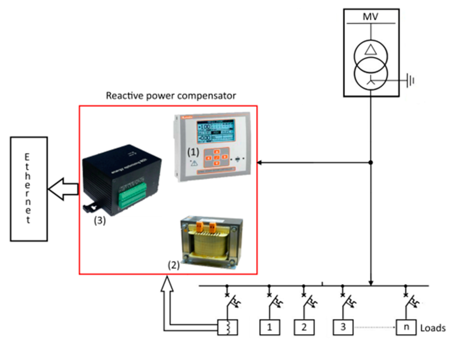
Preliminary measurements (selected results presented above) showed the need to install systems for the capacitive reactive power compensation. It was assumed, according to the recommendations of the energy supplier, that the ratio of inductive reactive energy to active energy (tg φ) can be a maximum of 0.4 in the settlement period. Therefore, the system regulates in hysteresis way by switching on current-compensated chokes in the range of 0.2 < tg φ < 0.4. Based on the recorded data, a reactive power compensation system was selected for the facility. The schematic diagram of the chosen power compensation system is shown in Figure 8. The choice was made in accordance with the general recommendations that are presented in [19,20]. The implemented reactive power compensation system consists of the DRLCG (1) regulator from Lovato Electric [21], the Elmond [2] ED1K reactor assembly [22], the ECV management and communication module (3) from Energy Management Systems [23]. The system of current-compensated chokes compensating capacitive reactive power was chosen on the basis of the average power measured during preliminary tests.
The following current-compensated choke system was applied:
  • Phase L1: two chokes L1a—1.0 kVar and L1b—0.5 kVar,
  • Phase L2: two chokes L2a—1.0 kVar and L2b—0.5 kVar,
  • Phase L3: three chokes L3a—1.0 kVar, L3b—1.0 kVar and L3c—0.5 kVar.
The above-mentioned approach enabled the authors to effectively control the compensation system, which simultaneously allows for the selection of compensated power.
The implemented system allows for compensation of capacitive reactive power and for online monitoring of basic energy parameters. An Internet application is currently used for monitoring the facility. The implemented management system enables, in the scope of both current and historical indications, the following actions:
  • Display:
    • Requirement for power (active, reactive, apparent)
    • Analysis of electrical efficiency indicators
    • Analysis of the maximum energy consumption and its basic quality parameters
  • Reporting:
    • Comparative comparisons for the indicated period
    • Invoicing
  • Cost prediction functions:
    • Forecasting energy consumption in assumed periods
    • Forecasting costs in case energy prices change
    • Determining the savings resulting from the use of a compensator
  • Functions of notification and control via email and/or Short Message Service in the event of:
    • Possibility of exceeding the ordered power
    • Alarms and events programmed in the system
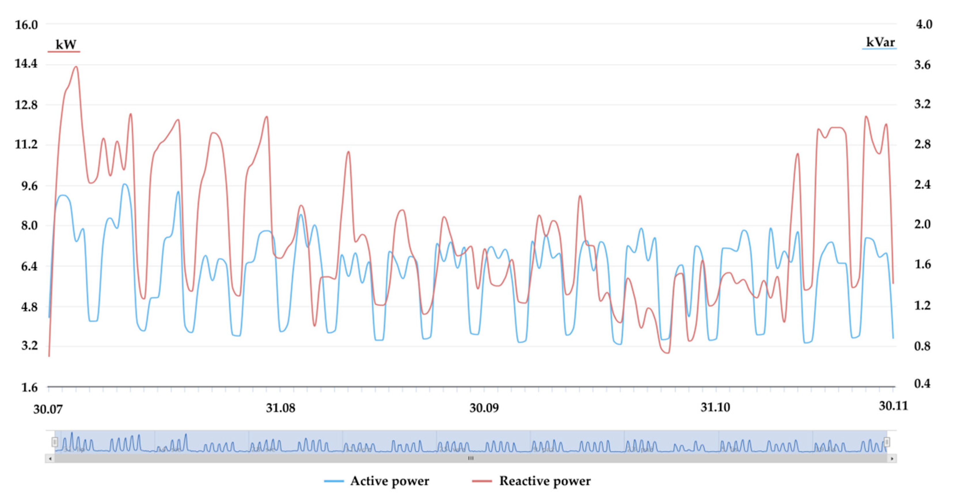
The above-realized functions are available online for the supervising system, which allows for the monitoring of the system on an ongoing basis and quick responses to occurring events. Figure 9 shows the recorded active and reactive power consumption in the period ranging from the system introduction to the end of November 2017. The results were obtained from the monitoring application, which is updated and enriched with new tools facilitating the analysis and operation of the system at the program layer.
The installed supervisory system allows for interventions in case of problems. At the same time, within half a year, the expenditures for the functioning of the system were partially (50%) compensated in the form of lower energy bills. It is assumed that full compensation for the incurred expenditures related to the implementation of the system will occur within 12 months of its introduction at current energy consumption.

5. Conclusions

The described problems seem to be common for many newly built or modernized facilities that use LED lighting sources. The possibilities of their occurrence were signaled in inter alia in [12] (showing the basic differences between the various types of applied lighting sources). Frequently carried out measurements indicate that the extensive application of energy-efficient LED lighting sources reduces the power demand by about 30% in relation to the sources used so far. Unfortunately, these systems are, in many cases, the source of disturbances causing further reduction of the power factor and additional distortion of the supply voltage. The obtained measurements indicate that, unfortunately, due to the design of tested LED lighting sources, there is a decrease in the power factor to a value of approximately 0.5 and increase in the crest factor to 4.5. The researched sources were characterized by power factors of about 0.5 which dropped to 0.4, along with an increase in harmonics in the supply voltage. In the case of vast application, the fundamental component of the current is ahead of the fundamental voltage component. This will result in charges for the consumption of capacitive reactive energy. However, this is related to the construction of popular (cheaper) sources of LED lighting. According to technical data declared by some manufacturers, the power factors should be 0.9 [24,25], though this seems to be a less popular solution due to the fact of it being more expensive. Currently, often in older facilities, the modernization of lighting installations involving the replacement of LED lighting sources is carried out. In some cases, it results in a change in the nature of the consumed reactive power from inductive to capacitive. The use of Energy Management Systems allows recording of these phenomena and proper selection of a reactive power compensator. In new facilities, compensators with chokes shall be installed instead of compensators with capacitors.
The conducted research allows for the conclusion that requirements concerning minimum power factors for LED power sources of low power (below 25 W) should also be introduced. Carried out measurements show that, when using such lighting sources in networks, where higher harmonics occur in the supply voltage, the power factor of these sources decreases. With considerable application, this can cause the problems described above, with the need to compensate the capacitive reactive power. In addition, while conducting the extension and/or modernization of a given facility, it is worthwhile to implement solutions that allow monitoring and optimizing the power consumption. The authors also suggest introducing a requirement for using small LED light sources (below 25 W) with a power factor of more than 0.9. This suggestion is recommended as a preventive. It is due to the fact that, in cases of constructed facilities equipped with a large number of LED light sources with unit powers lower than 25 W, the accumulation of the following phenomena may occur: an increase in the number of current and voltage harmonics and the generation of reactive power of the fundamental harmonic. Unfortunately, the introduction of such a requirement will surely generate an increase in the price of LED lighting sources.

Author Contributions

M.W. and S.G. conceived and designed the experiments; analyzed the data; wrote the paper.

Acknowledgments

The authors thank the company for permission to test object “STB INNOVATION CENTER Limited Liability Company S. K” based in Tczew 83-110 Skarszewska 23 street, Poland.

Conflicts of Interest

The authors declare no conflict of interest.

References

  1. Kwasnowski, P.; Fedorczak-Cisak, M.; Knap, K. Problems of Technology of Energy-Saving Buildings and Their Impact on Energy Efficiency in Buildings. IOP Conf. Ser. Mater. Sci. Eng. 2017, 245, 072043. [Google Scholar] [CrossRef] [Green Version]
  2. Kazmierkowski, M.P. Power Theories for Improved Power Quality (Pasko, M. and Benysek, G.; 2012) [Book News]. IEEE Ind. Electron. Mag. 2013, 7, 68–69. [Google Scholar] [CrossRef]
  3. Bunjongjit, S.; Ngaopitakkul, A.; Leelajindakrairerk, M. Analysis of harmonics in indoor Lighting System with LED and fluorescent luminaire. In Proceedings of the 2017 IEEE 3rd International Future Energy Electronics Conference and ECCE Asia (IFEEC 2017—ECCE Asia), Kaohsiung, Taiwan, 3–7 June 2017; pp. 2129–2132. [Google Scholar]
  4. Dolara, A.; Leva, S. Power Quality and Harmonic Analysis of End User Devices. Energies 2012, 5, 5453–5466. [Google Scholar] [CrossRef] [Green Version]
  5. Tulsky, V.N.; Vanin, A.S.; Tolba, M.A.; Sharova, A.Y.; Diab, A.A.Z. Study and analysis of power quality for an electric power distribution system—Case study: Moscow region. In Proceedings of the 2016 IEEE NW Russia Young Researchers in Electrical and Electronic Engineering Conference (EIConRusNW), St. Petersburg, Russia, 2–3 February 2016; pp. 710–716. [Google Scholar]
  6. Marah, B.; Bhavanam, Y.R.; Taylor, G.A.; Ekwue, A.O. Impact of electric vehicle charging systems on low voltage distribution networks. In Proceedings of the 2016 51st International Universities Power Engineering Conference (UPEC), Coimbra, Portugal, 6–9 September 2016; pp. 1–6. [Google Scholar]
  7. Tan, S.T.; Sun, X.W.; Demir, H.V.; DenBaars, S.P. Advances in the LED Materials and Architectures for Energy-Saving Solid-State Lighting Toward “Lighting Revolution”. IEEE Photonics J. 2012, 4, 613–619. [Google Scholar] [CrossRef] [Green Version]
  8. PF_Factor_california. Available online: https://pdfs.semanticscholar.org/2a03/8b20e758b6d60f050ae18746ca413dbaa48b.pdf (accessed on 19 January 2018).
  9. Bellia, L.; Bisegna, F.; Spada, G. Lighting in indoor environments: Visual and non-visual effects of light sources with different spectral power distributions. Build. Environ. 2011, 46, 1984–1992. [Google Scholar] [CrossRef]
  10. Salvadori, G.; Fantozzi, F.; Rocca, M.; Leccese, F. The Energy Audit Activity Focused on the Lighting Systems in Historical Buildings. Energies 2016, 9, 998. [Google Scholar] [CrossRef]
  11. Khan, N.; Abas Kalair, N. Comparative Study of energy saving light sources. Renew. Sustain. Energy Rev. 2011, 15, 296–309. [Google Scholar] [CrossRef]
  12. Aman, M.M.; Jasmon, G.B.; Mokhlis, H.; Bakar, A.H.A. Analysis of the performance of domestic lighting lamps. Spec. Sect. Transit. Pathw. Low Carbon Econ. 2013, 52, 482–500. [Google Scholar] [CrossRef]
  13. Amorim, R.; López, J.C.; Molina-Moreno, V.; Peña-García, A. Use of Natural Light vs. Cold LED Lighting in Installations for the Recovery of Victims of Gender Violence: Impact on Energy Consumption and Victims’ Recovery. Sustainability 2017, 9, 562. [Google Scholar] [CrossRef]
  14. Behar-Cohen, F.; Martinsons, C.; Viénot, F.; Zissis, G.; Barlier-Salsi, A.; Cesarini, J.P.; Enouf, O.; Garcia, M.; Picaud, S.; Attia, D. Light-emitting diodes (LED) for domestic lighting: Any risks for the eye? Prog. Retin. Eye Res. 2011, 30, 239–257. [Google Scholar] [CrossRef] [PubMed]
  15. Tang, Y.; Chen, Q.; Ju, P.; Jin, Y.; Shen, F.; Qi, B.; Xu, Z. Research on load characteristics of energy-saving lamp and LED lamp. In Proceedings of the 2016 IEEE International Conference on Power System Technology (POWERCON), Wollongong, Australia, 28 September–1 October 2016; pp. 1–5. [Google Scholar]
  16. TD_PQ-Box 200_en_160506.pdf. Available online: https://www.a-eberle.de/sites/default/files/media/TD_PQ-Box%20200_en_160506.pdf (accessed on 18 December 2017).
  17. 61500-acsource.pdf. Available online: http://www.chromausa.com/pdf/61500-acsource.pdf (accessed on 10 January 2018).
  18. IEEE. IEEE Standard Definitions for the Measurement of Electric Power Quantities Under Sinusoidal, Nonsinusoidal, Balanced, or Unbalanced Conditions; IEEE Std 1459-2010 Revis. IEEE Std 1459-2000; IEEE: Piscataway, NJ, USA, 2010; pp. 1–50. [Google Scholar] [CrossRef]
  19. Kabalci, E. Reactive Power Compensation in AC Power Systems. In Reactive Power Control in AC Power Systems: Fundamentals and Current Issues; Mahdavi Tabatabaei, N., Jafari Aghbolaghi, A., Bizon, N., Blaabjerg, F., Eds.; Springer International Publishing: Cham, Switzerland, 2017; pp. 275–315. ISBN 978-3-319-51118-4. [Google Scholar]
  20. Zobaa, A.F.; Aleem, S.H.E.A. A New Approach for Harmonic Distortion Minimization in Power Systems Supplying Nonlinear Loads. IEEE Trans. Ind. Inform. 2014, 10, 1401–1412. [Google Scholar] [CrossRef] [Green Version]
  21. PD87GB11_12.pdf. Available online: http://www.lovatoelectric.com/images/data/PD87GB11_12.pdf (accessed on 12 January 2018).
  22. Single-phase shunt reactors ED1K.pdf. Available online: http://www.en.elhand.pl/products/chokes/shunt-reactors/Single_phase_shunt_reactors (accessed on 19 January 2018).
  23. Zakladka2.pdf. Available online: https://www.ems.gda.pl/index.php/zakladka2?format=raw&task=download&fid=9 (accessed on 19 January 2018).
  24. USALED T8UNV Datasheet.pdf. Available online: https://usaled.com/media/pdf/USALED%20T8UNV%20Datasheet.pdf (accessed on 19 January 2018).
  25. USALED DLM Datasheet.pdf. Available online: https://usaled.com/media/pdf/USALED%20DLM%20Datasheet%20.pdf (accessed on 19 January 2018).
Figure 1. Diagram of the applied measurement setup.
Energies 11 01479 g001
Figure 2. The course of total power variation in the monitored period.
Energies 11 01479 g002
Figure 3. The course of power variation in the monitored period on individual phases L1, L2, L3.
Energies 11 01479 g003
Figure 4. The course of voltage and current in the L3 phase in the monitored facility.
Energies 11 01479 g004
Figure 5. The voltage and current course during the E1 light source test with the level of Test T4.
Energies 11 01479 g005
Figure 6. Chart of the power factor (PF) change for the tests.
Energies 11 01479 g006
Figure 7. Chart of the crest factor (CF) change for the tests.
Energies 11 01479 g007
Figure 8. Schematic diagram of the applied reactive power compensation system.
Energies 11 01479 g008
Figure 9. Screenshot of the supervisory application presenting active and reactive power consumption in the period of 1/August/2017–30/November/2017.
Energies 11 01479 g009
Table 1. Basic parameters declared by manufacturers of LED light sources.
ManufacturerSymbolPowerLight TemperatureLuminous FluxVoltagePower Factor
--WKlmV-
PilaE11427001521220–240ND *
PhilipsE21327001521220–240ND *
ToshibaE31127001055230ND *
KobiE41030008102300.5
* ND—value not declared by the manufacturer.
Table 2. Test voltage parameters during tests in an isolated power environment.
HarmonicsTest 1Test 2Test 3Test 4
SymbolT1T2T3T4
30.0%3.0%5.0%8.0%/90°
50.0%3.0%6.0%8.0%
70.0%2.0%5.0%8.0%/90°
90.0%1.5%1.5%0.0%
110.0%1.0%3.5%0.0%
130.0%1.0%3.0%0.0%
Table 3. Recorded total requirement for power of the monitored facility.
Power Maximum LoadAverage LoadMinimum Load
Total active power P (kW)15.79.97.7
Total reaction power QV (kVar)−6.4−4.8−3.2
Table 4. Active and reactive power consumption for individual phases.
Power Maximum LoadAverage LoadMinimum Load
Active power P L1 (kW)7.43.52.5
Active power P L2 (kW)2.81.10.7
Active power P L3 (kW)8.75.23.8
Reactive power QV L1 (kVar)−1.8−1.3−0.5
Reactive power QV L2 (kVar)−2.4−1.1−0.7
Reactive power QV L3 (kVar)−2.8−2.4−1.5
Table 5. Fundamental power factor (PFH1), THDU for individual phases and power factor.
ParameterL1L2L3
Fundamental PFH1 0.9270.9040.719
THDU (%)1.611.581.78
Power Factor0.812
Table 6. Measurement results of electrical parameters of LED lighting sources.
EUT/Test NumberVoltage (RMS)Real Power PReactive Power QVPower Factor PFCrest Factor CF
-VWVar--
E1/T1229.8014.19−21.490.563.58
E1/T2230.1014.12−20.960.583.43
E1/T3231.0114.27−26.810.503.53
E1/T4231.9914.19−26.930.503.82
E2/T1229.8013.26−21.350.503.16
E2/T2230.1013.12−20.400.512.89
E2/T3231.0313.14−26.590.404.35
E2/T4231.9813.31−21.350.404.31
E3/T1229.8010.74−17.020.502.93
E3/T2230.1010.76−16.740.502.89
E3/T3231.0010.89−21.800.413.44
E3/T4231.9110.86−21.890.413.41
E4/T1229.809.66−15.850.503.30
E4/T2230.109.59−15.160.502.97
E4/T3231.009.68−20.370.404.45
E4/T4231.909.85−20.970.404.34
Table 7. Determined average temperature increments of tested LED lighting sources.
Tested Facility/Test NumberAverage Temperature Increments (∆TAV)
-°C
E1/T156.0
E1/T256.1
E1/T356.2
E1/T457.5
E2/T164.0
E2/T264.2
E2/T364.8
E2/T465.1
E3/T159.6
E3/T259.4
E3/T359.6
E3/T460.1
E4/T167.3
E4/T266.9
E4/T370.1
E4/T471.8