Case Report

Sealing Failure Analysis on V-Shaped Sealing Rings of an Inserted Sealing Tool Used for Multistage Fracturing Processes

1
School of Mechatronic Engineering, Southwest Petroleum University, Chengdu 610500, China
2
Industrial Systems Engineering, University of Regina, Regina, SK S4S 0A2, Canada
3
Sanden Chongqing Automative Air Conditionting CO. Ltd., Chongqing 401120, China
4
Engeering Technology Reasearch Insititute, PetroChina Southwest Oil & Gas Field Company, Chengdu 610017, China
*
Authors to whom correspondence should be addressed.
Energies 2018, 11(6), 1432; https://doi.org/10.3390/en11061432
Submission received: 3 April 2018 / Revised: 23 May 2018 / Accepted: 31 May 2018 / Published: 3 June 2018

Abstract

:
The inserted sealing tool is a critical downhole implement that is used to balance the downhole pressure in multistage fracturing operations and prevent fracturing fluid from overflow and/or backward flow. The sealing ring of an inserted sealing tool plays an important role in downhole sealing since a sealing failure would ail the fracturing operation. In order to improve the sealing performance and reduce the potential fracturing failures, this research aims to investigate the influence of V-shaped sealing ring geometries on sealing performance. Constitutive experiments of rubber materials were carried out and the parameters of the constitutive relationship of rubber materials were obtained. A two-dimensional axisymmetric model considering the sealing ring has been established and influences are investigated with considerations of various system parameters and operating conditions. It is found that the stresses concentrated at the shoulder and inner vertex of the sealing ring have direct impact on the damage of the sealing rings under operational conditions. Moreover, the sealing interference, among several other factors, greatly affects the life of the sealing ring. A new design of the sealing ring is suggested with optimized geometric parameters. Its geometric parameters are the edge height of 5 mm, the vertex angle of 90°–100°, and the interference of 0.1 mm, which show a better performance and prolonged operation life of the sealing ring.

1. Introduction

In the present, oil and gas resources are still the main source of energy [1]. The development of oil and gas exploration and development technology occupies an important position in the oil and gas industry [2]. Multistage fracturing technology is a method widely used in oil/gas reservoir stimulation. In the process of performing the multistage fracturing [3,4], an inserted sealing tool is frequently used in downhole operations to connect the upper tubing and lower fracturing string so as to balance the downhole pressure and prevent the fracturing fluid from flowing backward or overflowing. A typical inserted sealing tool used in the field is shown in Figure 1.
During the fracturing, a sealing area is formed between the sealing assembly of the inserted sealing tool and the casing pipe. The fracturing fluid, which comes from the fracturing pump, pushes the pitching sleeves open and cracks the reservoir wall of an oil/gas well. As a result, oil and gas may flow out from the fractured media in production phase. Once the sealing fails, the fracturing fluid will overflow directly to the wellhead. It makes the pitching sleeve unable to open, eventually triggering the fracturing failure.
An inserted sealing tool consists of one support ring, six V-shaped sealing rings, one spacer ring, and one press ring (as shown in Figure 1). The six sealing rings are divided by a spacer ring. The sixth sealing ring and the first sealing ring are in direct contact with the support ring and the press ring. The support ring supports and positions the whole sealing system.
The sealing area is formed between the V-shaped sealing rings and the inner wall of the casing pipe to prevent the high pressure liquid at the well bottom from leaking, thus maintaining the bottom hole pressure. The sealing performance of the V-shaped sealing ring is critically important for the multistage fracturing performance. In order to improve its sealing performance, researchers and engineers, with theoretical, numerical, and experimental approaches, tried to investigate the factors that affect the sealing performance of the V-shaped sealing rings.
Diany and Bouzid [5] constructed a sealing mathematical model on the basis of thick wall cylinder theory; however, the size of packing or the amount of interference on the impact of stress and deformation were not considered. Zhou et al. [6] used an FEA (Finite Element Analysis) method to study the sealing failure of a drilling mud pump plunger under ultrahigh pressure and ultradeep conditions. The distribution of contact stress of the V-shaped sealing ring was studied in their research, and it was noted that the primary reason for sealing failure was that the design of the sealing ring structure had flaws. Zhu et al. [7] studied the relationship between the axial load and the contact stress through a mathematical model with a differential equation. By using elastic mechanics theory, Qin et al. [8] established a model to study how the pressing force and sealing interference affect the stress and deformation of V-shaped packing seals under no-friction condition. Gistad and Gilstad [9] designed a sealing assembly for a high-pressure plunger pump that could withstand the pressure of over 69 MPa. A new sealing structure with a corrugated surface was proposed by Ellerhorst and Kraimer [10] and their experiments demonstrated that the sealing performance was improved with implementation of their new sealing structure, but the operation life of the sealing ring was reduced due to the significantly increased shear stress. Materials of V-shaped sealing rings also affect the sealing performance of the sealing ring. The research conducted by Zhang [11] revealed that an asbestos-compiled sealing material could deliver a good sealing performance and a long working life under high temperature and high pressure. Zavos et al. [12] studied how the waviness and straightness affect the mechanism of friction and the structural integrity of the piston ring. Additionally, introducing polytetrafluoroethylene (PTFE) into the sealing ring could reduce the coefficient of friction thus, improving the wear resistance and the service life of the ring [13].
Although numerous studies about V-shaped sealing rings can be found in archived documents, there is still a lack of a systematic and comprehensive study on the sealing performance of V-shaped sealing rings and the effects of main factors affecting the performance and operation life of the sealing ring. It is also noted that most investigations found in the literature only consider a single factor, however, multiple factors are found affecting the performance, such as the geometry of V-shaped sealing rings, material properties, working medium, working pressure, and working temperature. This research is to investigate the combined effects of geometric dimensions and sealing interference on the performance and operation of the sealing ring by using a numerical approach. On the basis of the strain–stress experiments and data processing, a numerical simulation model has been constructed and also the constitutive parameters have been obtained. Optimized structural parameters of the V-shaped sealing ring and sealing interference are identified for the design of V-shaped sealing rings with better sealing operation and longer working life.

2. Hyperelastic Constitutive Model of Rubber Material

The V-shaped sealing ring, which is used in the inserted sealing tool, is a kind of highly nonlinear elastomer [14]. The material of the V-shaped sealing ring is hydrogenated nitrile rubber. When not considering the influence of time, such as rubber material creep, stress relaxation, and the Mullins effect, rubber material can be regarded as an isotropic and incompressible hyperelastic material [15]. This study adopts the constitutive relationship of rubber material based on the phenomenological theory, and the strain energy density function can be expressed as the following [16]:
W = i + j = 1 N C i j ( I 1 3 ) i ( I 2 3 ) j + k = 1 N 1 d k ( I 3 2 1 ) 2 k
where C i j is the parameter of hyperelastic constitutive model that can be acquired by experiments. I 1 , I 2 , and I 3 are the Cauchy–Green deformation tensor invariants.
For an isotropic and incompressible hyperelastic body, I 3 = 1 . Thus, the Equation (1) can be simplified as:
W = i + j = 1 N C i j ( I 1 3 ) i ( I 2 3 ) j
I 1 = λ 1 2 + λ 2 2 + λ 3 2 I 2 = λ 1 2 λ 2 2 + λ 2 3 λ 3 2 + λ 3 2 λ 1 2 λ i = 1 + γ i
where λ 1 , λ 2 , and λ 3 are the principal stretch ratios.
Yamashita and Kawabata found that W / I 2 was close to zero through analyzing the data of a rubber uniaxial experiment and shearing experiment [17]. Yeoh O. H. [18] deduced three parameters for the strain energy density function according to W / I 2 = 0 as follows:
W = C 10 ( I 1 3 ) + C 20 ( I 1 3 ) 2 + C 30 ( I 1 3 ) 3
The relationship between Kirchhoff stress tensor σ i and Cauchy–Green strain tensor γ i can be described by the following equation:
σ i = W I 1 I 1 γ i + W I 2 I 2 γ i + W I 3 I 3 γ i
According to Equations (3) and (5), stress tensor σ i and principal stretch ratios λ i have the following relationship:
{ σ 1 = 2 λ 1 [ W I 1 + ( λ 2 2 + λ 3 2 ) W I 2 + λ 2 2 λ 3 2 W I 3 ] σ 2 = 2 λ 2 [ W I 1 + ( λ 1 2 + λ 3 2 ) W I 2 + λ 1 2 λ 3 2 W I 3 ] σ 3 = 2 λ 3 [ W I 1 + ( λ 1 2 + λ 2 2 ) W I 2 + λ 1 2 λ 2 2 W I 3 ]
Through a stress–strain uniaxial test of rubber material, σ 2 = σ 3 = 0 , λ 2 2 = λ 3 2 = 1 / λ 1 . Therefore, Equation (6) can be modified to:
σ 1 = 2 ( λ 1 λ 1 2 ) ( W I 1 + λ 2 2 W I 2 )
According to Equations (3), (4), and (7), the relationship between stress tensor σ 1 and principal stretch ratios λ 1 can be described as:
σ 1 = 2 ( λ 1 λ 1 2 ) [ C 10 + 2 C 20 ( λ 1 2 + λ 1 1 3 ) + 3 C 30 ( λ 1 2 + λ 1 1 3 ) 2 ]
In this study, the parameters of the Yeoh model were acquired by the uniaxial stress–strain experiment and data fitting through the software package. Then, a rubber uniaxial mechanical performance experiment was conducted according to the criteria of stress–strain properties of vulcanized rubber and thermoplastic rubber [19,20], as shown in Figure 2.
By fitting the data acquired in the uniaxial tests, the parameters of the constitutive model were obtained, which were C 10 = 1.4109 , C 20 = 1.3113 × 10 2 , and C 30 = 1.492 × 10 4 , respectively. Figure 3 illustrates the experimental stress–strain curves and the data fitting of the Yeoh model. Meanwhile, according to the result of uniaxial tensile test, the fracture tensile strength of rubber used in the V-shaped sealing ring was 25.54 MPa and the tensile elongation was 5.73.

3. Two-Dimensional Axisymmetric Simulation Model

Since the structure of the inserted sealing tool and the loads are axisymmetric, a two-dimensional axisymmetric finite element model was established (Figure 4a). According to the working conditions of the inserted sealing tool, the support ring will not move when it is anchored. Thus, the support ring was imposed as a fixed constraint. In addition, the pressure ring will move upwards under the load P from the well bottom in the Y direction, while the V-shaped sealing ring will be pushed upwards and expand radially until the sealing process finishes. Therefore, an axial load in the Y direction was applied to the press ring and the interaction property among the adjacent parts were set as contact type. The friction coefficient among the metal components was 0.1, the friction coefficient between the V-shaped sealing rings and the metal components was 0.3, and finally, the coefficient of friction among the V-shaped sealing rings was 0.45 [21].
The physical parameters of each component are shown in Table 1. Parameters of the rubber material are set as described in Section 2. The element type in the FEA model of the V-shaped sealing ring was CAX4H (a 4-node bilinear axisymmetric quadrilateral, hybrid, constant pressure). The element in the FEA model of the support ring, spacer ring, press ring, casing pipe, and central pipe was CAX4I (a 4-node bilinear axisymmetric quadrilateral, incompatible modes). This research focuses on the deformation and stress of the V-shaped seal ring when it is at work. Therefore, the seal ring simulation grid was more densely divided than other components (Figure 4b).

4. Results

4.1. Failure Analysis and Reliability Validation

Figure 5 shows the numerical simulation result and the main failure types of the V-shaped sealing ring which occurred in the field. From the photos of the V-shaped sealing ring applied in the field, it can be seen that there were some areas on the shoulders where rubber peeled off and the inner vertex angle of the sealing ring existed where sealing failure was likely to occur. The numerical simulation results show that high stress mainly appeared in the shoulders and the inner vertex angle of the sealing ring. Through comparing the numerical simulation result and failure figures, it can be concluded that stress concentration on the shoulders and the inner vertex angle led to the rubber peeling off. The stress concentration areas in the numerical simulation results agree well with the sealing failure area observed in the oil/gas production field. This indicates that the two-dimensional axisymmetric numerical simulation model of the V-shaped sealing ring established in this research is of high rationality and can be used to study the sealing failure of V-shaped sealing rings in inserted sealing tools.

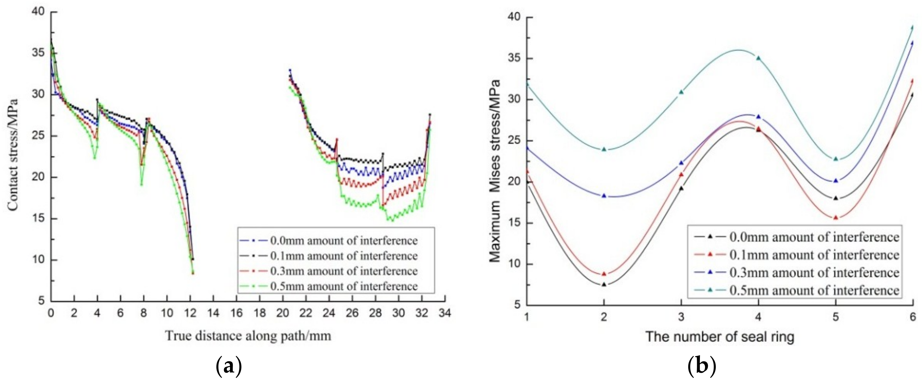
4.2. The Influence of Sealing Interference Magnitude

A suitable size of V-shaped sealing ring was chosen according to reference [22], whose sealing edge was 4 mm and vertex angle was 90°. Sealing interference magnitude is defined as the difference between the outer diameter of the V-shaped sealing ring and the inner diameter of the casing pipe in the initial state when the inserted sealing tool has not yet been placed into the casing pipe. By changing the outer diameter, different magnitudes of sealing interference between the sealing ring and the casing pipe are obtained as well as the distributions of contact stress and Mises stress under those different sealing interferences.
Mises stress is regarded as a critical criteria of rubber’s damage. The areas where the Mises stress is more concentrated are more prone to cracking, and then the sealing ring is torn more easily. Figure 6 illustrates Mises stress nephograms under four different sealing interferences. The stress nephograms reveal that high stress values mainly appeared in the shoulders and the inner vertex angle of the sealing rings, and when the sealing interference increased, the area of high Mises stress gradually increased. Moreover, a growing number of sealing rings began to appear in the high-Mises-stress area. It indicates that if the sealing interference is too large, cracks will occur at the shoulder as well as the inner vertex angle of V-shaped sealing rings in the engineering process, thus eventually triggering sealing failure. As found in practical use, the shoulder and inner vertex of the V-shaped sealing ring are indeed easily damaged, thus triggering sealing failure.
Figure 7 shows the contact stress distribution of V-shaped sealing rings and the maximum Mises stress of each sealing ring. The actual distance along the path refers to the coordinate values in the Y-direction, and the coordinate system origin relates to the first sealing ring (loading position).
The following conclusions can be obtained from the simulation results:
(1)
Figure 7a shows that the contact stress among the first five sealing rings decreased with the increase of the actual distance along the path, while increasing on the sixth sealing ring. As the sealing interference increased, the contact stress of the sealing assembly initially increased and then decreased, which means the sealing ability of the V-shaped sealing ring exhibited the same trend.
(2)
Figure 7b shows that the surfaces of the four sealing rings which directly contacted the metal components (i.e., support ring, spacer ring, and press ring—see Figure 4) had higher Mises stresses when compared with the other two sealing rings, i.e., the third and fourth sealing rings. The maximum Mises stress changing trends were similar under different sealing interferences. With the increase of the sealing interference, the maximum Mises stress of the sealing ring gradually increased and the growth became more dramatic, which shows that the sealing interference magnitude had a significant effect on the working life of V-shaped sealing rings.
(3)
In summary, compared with other sealing structures, the structure with 0.1 mm sealing interference had a higher contact stress and lower Mises stress, which means that it has better sealing performance and is not easily damaged.

4.3. The Influence of Height of Sealing Ring Edge

The V-shaped sealing ring is applied on the status that the sealing ring has high contact stress and the degenerative rate of contact stress is slow. Based on the criteria above, the distributions of contact stress and Mises stress with the sealing interference of 0.1 mm and the vertex angle of 90° under different heights of V-shaped sealing ring edge have been analyzed, as shown in Figure 8. Since the height of the sealing ring edge was not the same, in order to fairly compare stress distribution, 3 mm was taken as the standard height, and then all the sealing rings had the same initial coordinate value.
The following results were observed from the above data:
(1)
As shown in Figure 8a, as the height of the sealing ring edge increased, the contact stress of the sealing assembly initially increased and then decreased. The attenuation rate of the contact stress decreased.
(2)
As shown in Figure 8b, changing the height of the sealing ring did not affect the trend of the maximum Mises stress, and it had a certain influence on each sealing ring, which means the height of the sealing ring edge had little influence on the sealing failure of the V-shaped sealing ring.
(3)
According to the stress distribution curve, the sealing ring with the edge height of 5 mm had higher contact stress than the others, and its attenuation rate of the contact stress was lower. Therefore, under certain conditions, the sealing ring with the edge height of 5 mm performs better than the others.

4.4. The Influence of Magnitude of Sealing Ring Vertex Angle

According to the analysis above, under 0.1 mm sealing interference, the sealing ring with the sealing edge height of 5 mm performed better. In order to acquire the stress distribution of a V-shaped sealing ring under different vertex angles, this paper analyzes the condition of four vertex angles. The conclusion is shown in Figure 9.
The following results are drawn from the numerical simulation results:
(1)
As shown in Figure 9a, as the vertex angle of the sealing ring increased, the contact stress of the sealing assembly gradually increased. When the vertex angle reached 90°, the contact stress barely changed and the attenuation rate remained the same.
(2)
As shown in Figure 9b, when the sealing ring vertex angle changed, the trend and value of the maximum Mises stress of the first, second, and fourth sealing rings only changed a little, which means the vertex angle has little influence on the sealing failure of V-shaped sealing rings.
(3)
When the vertex angle ranged from 90° to 100°, the values of contact stress and maximum Mises stress were very close. Considering the fact that the contact stress and the maximum Mises stress directly affect the sealing performance, this paper recommends a V-shaped sealing ring with the vertex angle in the range of 90° to 100°.

5. Discussion

The inserted sealing tool is a key downhole tool for the multistage fracturing technology and its sealing performance directly affects the success of fracturing. In order to analyze and solve the problem of sealing failure when the V-shaped sealing ring is at work, it is particularly important to understand the law and causes of the deformation and stress distribution of the sealing ring. The following discussions relate to the deformation and stress distribution based on the working principle of the inserted sealing tool and the above numerical simulation results above under various working conditions.
(1)
The contact stress among the first five sealing rings gradually decreased because of the friction between the V-shape sealing ring and the casing pipe, which caused the compression deformation to decrease. However, in the sixth sealing ring, the closer it was to the support ring, the higher the contact stress was. The support ring was fixed and its deformation was minimal; therefore, the load was not able to transmit and the sealing rings were extremely deformed.
(2)
In the sealing process, large areas of stress concentration exists around the shoulders of the V-shaped sealing ring that contacts the metal components. The reason is that the metal components would not be deformed under loads; therefore, the entire load transmits to the shoulder of the sealing ring, causing considerable deformation. The primary reason is that the radial deformation increases while the concave design of the vertex angle prevents the stress from spreading, which leads to stress concentration and ultimately cracks with the V-shaped sealing ring damaged.
(3)
The height of sealing edge and vertex angle of the V-shaped sealing ring have little influence on the Mises stress because, under a given sealing interference, the axial load is fixed and the radial distortion is the same. Therefore, the deformation of the V-shaped sealing ring is almost the same, and the change in the maximum Mises stress is very limited.

6. Conclusions

A two-dimensional axisymmetric model has been established to analyze and optimize a V-shaped sealing ring of an inserted sealing tool used for multistage fracturing processes, including the sealing interference magnitude, height of sealing edge, and vertex angle, with implementation of a constitutive relation obtained experimentally for the sealing ring material. By the findings of the research, the following conclusions can be drawn:
(1)
The contact stress of the first V-shaped sealing ring was the largest, which means the first sealing ring played a predominate role in the sealing. The largest Mises stress was also found at the first ring. This implies that this ring may fail first among all the other sealing rings.
(2)
Stress concentrations exist at the shoulder and inner vertex of the V-shaped sealing ring. These stress concentration areas agree with what is observed in the oil/gas production field.
(3)
The magnitude of the sealing interference greatly influences the stress concentration and the life of the sealing ring, as per the results of the research. It suggests that the sealing interference should be seriously considered in the design of sealing rings, to be able to reduce the stress concentrations and therefore enlarge the operation life of the rings. Meanwhile, the height of sealing edge and vertex angle have little influence on the stress concentration and the life of the sealing ring.
(4)
Optimized ring parameters are determined in the research for designing a new V-shaped sealing ring with optimal sealing and prolonged operation life. Specifically, the optimal parameter found for the edge height is 5 mm, optimal sealing interference is 0.1 mm, and optimal range of vertex angle is between 90° and 100°, under the conditions employed in the research.
The findings of the research offer guidance for designing and manufacturing V-shaped sealing rings with excellent sealing performance and extended operation life.

Author Contributions

All the authors contributed to publishing this paper. G.H. analyzed the numerical simulation data and wrote the paper; G.W. and P.Z. designed the research framework; L.D. reviewed and revised the original paper; M.L. and Y.F. designed and performed the experiments and analyzed the experimental data.

Acknowledgments

The study is supported by the Science and Technology Innovation Talent Engineering Project of Sichuan Province (2017RZ0057), Sichuan Youth Science & Technology Foundation (2017JQ0029) and Graduate Student Innovation Fund of School of Mechatronic Engineering. Southwest Petroleum University (CX2014BZ06, CX2015SY03). The authors’ grateful thanks also go to the University of Regina for its supports provided to the research.

Conflicts of Interest

The authors declare no conflict of interest.

References

  1. Lu, H.; Wu, X.; Huang, K. Study on the Effect of Reciprocating Pump Pipeline System Vibration on Oil Transportation Stations. Energies 2018, 11, 132. [Google Scholar] [CrossRef]
  2. Hu, G.; Zhang, P.; Wang, G.; Zhu, H.; Li, Q.; Zhao, S.; Qiao, K.; Wang, T. Performance study of erosion resistance on throttle valve of managed pressure drilling. J. Pet. Sci. Eng. 2017, 156, 29–40. [Google Scholar] [CrossRef]
  3. He, Y.; Cheng, S.; Rui, Z.; Qin, J.; Fu, L.; Shi, J.; Wang, Y.; Li, D.; Patil, S.; Yu, H.; et al. An Improved Rate-Transient Analysis Model of Multi-Fractured Horizontal Wells with Non-Uniform Hydraulic Fracture Properties. Energies 2018, 11, 393. [Google Scholar] [CrossRef]
  4. Zhang, D.; Dai, Y.; Ma, X.; Zhang, L.; Zhong, B.; Wu, J.; Tao, Z. An Analysis for the Influences of Fracture Network System on Multi-Stage Fractured Horizontal Well Productivity in Shale Gas Reservoirs. Energies 2018, 11, 414. [Google Scholar] [CrossRef]
  5. Diany, M.; Bouzid, A.H. Analytical evaluation of stresses and displacements of stuffing-box packing based on a flexibility analysis. Tribol. Int. 2009, 42, 980–986. [Google Scholar] [CrossRef]
  6. Zhou, Y.; Huang, Z.; Bu, Y.; Qiu, C.; Yuan, Y. Simulation studies on drilling mud pump plunger seal failure under ultrahigh pressure and ultradeep conditions. Eng. Fail. Anal. 2014, 45, 142–150. [Google Scholar] [CrossRef]
  7. Zhu, W.B.; Zhou, G.; Wang, H.S. Research on axial pressure distributionof plunger and seal pair in fracturing pump. Drill. Prod. Technol. 2007, 30, 91–93. [Google Scholar]
  8. Qin, Y.; Wang, C.; Zhou, Q.; An, Q. Mechanics calculation method for V-type sealing ring in compression process. J. East China Univ. Sci. Technol. Sci. Ed. 2013, 39, 108–114. [Google Scholar]
  9. Gilstad, B.C.; Gilstad, D.W. Plunger Sealing Ring. U.S. Patent 8,276,918, 2 October 2012. [Google Scholar]
  10. Ellerhorst, R.J.; Kraimer, R.H. Conforming Plunger Seal Assembly. U.S. Patent 5,115,979, 26 May 1991. [Google Scholar]
  11. Zhang, X. New sealing packing. Pump Technol. 1997, 5, 45–48. [Google Scholar]
  12. Zavos, A.; Nikolakopoulos, P.G. Waviness and straightness of cylinder and textured piston ring tribo pair. Int. J. Struct. Integr. 2015, 6, 300–324. [Google Scholar] [CrossRef]
  13. Huang, J.; Lee, Y.H. Evaluation of uni-axially expanded PTFE as a gasket material for fluid sealing applications. Mater. Chem. Phys. 2001, 70, 197–207. [Google Scholar] [CrossRef]
  14. Kim, J.J.; Kim, H.Y. Shape design of an engine mount by a method of parameter optimization. Comput. Struct. 1997, 65, 725–731. [Google Scholar] [CrossRef]
  15. Chagnon, G.; Verron, E.; Marckmann, G.; Gornet, L. Development of new constitutive equations for the Mullins effect in rubber using the network alteration theory. Int. J. Solids Struct. 2006, 43, 6817–6831. [Google Scholar] [CrossRef] [Green Version]
  16. Ogden, R.W. Non-Linear Elastic Deformations; Courier Corporation: New York, NY, USA, 1997. [Google Scholar]
  17. Yamashita, Y.; Kawabata, S. Approximated form of the strain energy-density function of carbon-black filled rubbers for industrial applications. Nippon Gomu Kyokaishi J. Soc. Rubber Ind. Jpn. 1992, 65, 517–528. [Google Scholar] [CrossRef]
  18. Yeoh, O.H. Characterization of elastic properties of carbon black-filled rubber vulcanization. Rubber Chem. Technol. 1990, 63, 792–805. [Google Scholar] [CrossRef]
  19. International Organization for Standardization. Rubber, Vulcanized or Thermoplastic—Determination of Tensile Stress-Strain Properties; ISO 37; ISO: Geneva, Switzerland, 2011. [Google Scholar]
  20. International Organization for Standardization. Rubber, Vulcanized or Thermoplastic—Determination of Compression Stress-Strain Properties; ISO 7743; ISO: Geneva, Switzerland, 2011; ISBN 978-0-580-66331-4. [Google Scholar]
  21. Ma, W.; Qu, B.; Guan, F. Effect of the friction coefficient for contact pressure of packer rubber. Proc. Inst. Mech. Eng. Part C J. Mech. Eng. Sci. 2014, 228, 2881–2887. [Google Scholar] [CrossRef]
  22. China Machinery Industry Federation. VD-Shaped Rubber Sealing Ring; JB/T 6994; China Machine Press: Beijing, China, 2007. [Google Scholar]
Figure 1. Inserted sealing tool: 1-casing pipe, 2-central pipe, 3-press ring, 4-sealing ring, 5-spacer ring, 6-support ring.
Energies 11 01432 g001
Figure 2. The mechanics performance test of rubber: (a) uniaxial tensile test; (b) uniaxial compression test.
Energies 11 01432 g002
Figure 3. The experimental stress–strain curves and the data fitting of the Yeoh model.
Energies 11 01432 g003
Figure 4. Finite element model: (a) geometry model and boundary conditions (b) meshing.
Energies 11 01432 g004
Figure 5. Result of numerical simulation and failures of the V-shaped sealing rings in the field.
Energies 11 01432 g005
Figure 6. Distribution of Mises stress for the V-shaped sealing rings under different sealing interference magnitude.
Energies 11 01432 g006
Figure 7. The stress distribution curve of sealing rings under different sealing interference magnitude: (a) contact stress distribution curve; (b) Mises stress distribution curve.
Energies 11 01432 g007
Figure 8. The stress distribution curve of sealing ring under different heights of sealing edge: (a) contact stress distribution curve; (b) Mises stress distribution curve.
Energies 11 01432 g008
Figure 9. The stress distribution curve of sealing ring under different vertex angle: (a) contact stress distribution curve; (b) Mises stress distribution curve.
Energies 11 01432 g009
Table 1. Physical parameters.
ComponentMaterialElastic Modulus/MPaPoisson’s RatioDensity/kg*m−3
Casing pipeP110206,0000.2807870
Central pipe40CrNiMoA209,0000.2957870
Press ring45209,0000.2697890
Support ring45209,0000.2697890
Spacer ring45209,0000.2697890
Sealing ringHydrogenated nitrile rubber/0.491400

