Article

Near-Wall Thermal Processes in an Inclined Impinging Jet: Analysis of Heat Transport and Entropy Generation Mechanisms

1
Institute of Energy and Power Plant Technology, Technische Universität Darmstadt, 64287 Darmstadt, Germany
2
Darmstadt Graduate School of Energy Science and Engineering, Technische Universität Darmstadt, 64287 Darmstadt, Germany
3
Laboratoire de Génies des Procédés et Thermodynamique, Institut Supérieur des Sciences et Techniques Appliquées, B.P. 6534 Kinshasa 31 NDOLO, D.R. Congo
*
Author to whom correspondence should be addressed.
Energies 2018, 11(6), 1354; https://doi.org/10.3390/en11061354
Submission received: 29 April 2018 / Revised: 21 May 2018 / Accepted: 22 May 2018 / Published: 25 May 2018
(This article belongs to the Section I: Energy Fundamentals and Conversion)

Abstract

:
In this work, near-wall thermal transport processes and entropy generation mechanisms in a turbulent jet impinging on a 45 -inclined heated surface are investigated using a direct numerical simulation (DNS). The objectives are to analyze the subtle mechanisms of heat transport in the vicinity of an inclined impinged wall, to determine the causes of irreversibilities that are responsible for the reduction of performance of impingement cooling applications and to provide a comprehensive dataset for model development and validation. Results for near-wall thermal characteristics including heat fluxes are analyzed. An entropy production map is provided from the second law analysis. The following main outcomes can be drawn from this study: (1) the location of peak heat transfer occurs not directly at the stagnation point; instead, it is slightly shifted towards the compression side of the jet, while at this region, the heat is transported counter to the temperature gradient; (2) turbulent thermal and fluid flow transport processes around the stagnation point are considerably different from those found in other near-wall-dominated flows and are strongly non-equilibrium in nature; (3) heat fluxes appear highly anisotropic especially in the vicinity of the impinged wall; (4) in particular, the heated wall acts as a strong source of irreversibility for both entropy production related to viscous dissipation and to heat conduction. All these findings imply that a careful design of the impinged plate is particularly important in order to use energy in such a thermal arrangement effectively. Finally, this study confirms that the estimation of the turbulent part of the entropy production based on turbulence dissipation rates in non-reacting, non-isothermal fluid flows represents a reliable approximate approach within the second law analysis, likewise in the context of computationally less expensive simulation techniques like RANS and/or LES.

1. Introduction

In order to improve the thermal efficiency, fuel economy and thermodynamic performance of advanced gas turbines, very high turbine inlet temperatures of about 1200–1500 C [1] are employed, which can exceed the material melting point of the components inside the gas turbine. Therefore, effective cooling arrangements with high heat transfer coefficients (typically in the range of 1000–3000 W/m 2 K [2]) are required to allow turbine operations without failure. In this regard, jet impinging cooling combined with internal fins, cooling passages and effusion holes for film cooling has proven to be an efficient cooling strategy and is therefore commonly applied in modern gas turbines. Thereby, relatively cold air extracted from the compressor of the turbine engine is bypassed to perforated internal walls to form an array of impinging jets in order to cool the blade exterior walls [2]. Upon exiting the blade through discretely located effusion holes or slots, the bypassed air provides a coolant film to shield the outside surface of the blade from the hot combustion gas. Besides the turbine blades and vanes, jet impinging cooling is also employed to cool combustor walls and the turbine case/liner of gas turbine engines [2], making the impingement cooling an essential component in the engineering design of modern gas turbine engines.
Apart from the gas turbine engines, impinging cooling has also found favor as a means of heat transfer equipment in a variety of other engineering applications like cooling of electronic components or quenching of metals and glass because it provides a very effective and flexible way to transfer thermal energy between a target surface and coolant fluid. Compared to conventional flow arrangements like free wall-parallel flows, impinging cooling enables up to threefold higher heat transfer coefficients at a given maximum flow speed [2]. Moreover, it has been observed that the jet dynamics and heat transfer depend on a large number of parameters, such as nozzle shapes, Reynolds number, inflow conditions, jet-to-plate spacing, target plate inclination, Prandtl number, and many more, which impede the optimization of engineering systems where thermal control is often carried out by means of impinging cooling. Moreover, the underlying physics in turbulent impinging jets is manifold and not unique since such flows feature very complex dynamics with interlinked effects including stagnation points, shear flow boundary layers, strong streamline curvatures and anomalies in the distribution of Nusselt numbers. It is therefore not surprising that in the last few decades, impinging cooling has been the subject of extensive research to gain insights into the subtle physical mechanisms and to identify preferred operating conditions along with practical guidelines for its general usage. An overview of experiments, numerical studies and available empirical correlations of impinging cooling can be found in a number of reviews, e.g., [3,4,5,6,7,8,9].
Focusing on heat transport in impinging jets, several researchers measured local Nusselt numbers for fully-developed circular impinging jets with respect to the jet-to-plate spacing H / D and jet Reynolds number R e j (see, e.g., [10,11,12,13]). In these experimental studies, emphasis was placed on a Reynolds number range from 4000–80,000 and a H / D interval from 0.5 –12, representing conventional gas jet installations for heat transfer [2]. In this context, it was concluded that heat transfer can be intensified by increasing R e j and/or decreasing H / D . Furthermore, it was observed that the variation of the mean wall heat transfer appears non-monotonic in the radial direction with two distinctive peaks occurring in the case of small jet-to-plate spacings ( H / D < 3 [13]) and above a critical Reynolds number of R e j , c r i t > 3000 [3]. The first peak, which is located in the vicinity of the stagnation point, is believed to be caused by a strong acceleration of the fluid away from the center of the jet and with a flapping of the impingement position [14]. The secondary peak appears approximately two nozzle diameters away from the stagnation point, which is thought to be linked to large-scale vortical structures issuing from the jet shear layer [15]. Further, the influence of nozzle shapes on the heat transfer characteristic of impinging gas jets has been also investigated in various experimental studies, e.g., [16,17,18,19,20,21]. In this regard, it was found that the shape of nozzle influences considerably the distribution of the local Nusselt number with the highest heat transfer coefficients in the case of circular orifices compared to elliptical, square, rectangular or triangle shapes. Varying the inclination of the impinged plate, a few experimental studies have explored the effect of target plate inclination angle on the heat transfer distribution of impinging jets, e.g., [22,23,24,25,26]. It was concluded that the location of peak heat transfer is shifted towards the compression side as the inclination increases [22] and that averaged Nusselt numbers increase with decreasing inclination [26]. Other influencing parameters on the heat transfer characteristic of impinging jets like inflow temperature, interaction with cross-flow, acoustic and mechanical excitation, jet arrays, jet inflow oscillation, surface curvature, rotating target plates or surface roughness have been also addressed in numerous experimental studies (see, e.g., [14,19,27,28,29,30,31,32]).
Despite significant progress towards a better understanding of the various physical phenomena taking place in impinging jet cooling, many issues remained open due to limitations of present measurement techniques, especially in the vicinity of the impinged wall where steep gradients and small turbulent flow scales make measurements very difficult. In order to circumvent these limitations, several numerical simulations have been initiated. Especially, wall-resolved LES [33,34,35,36,37,38,39,40] and direct numerical simulation (DNS) [41,42,43,44,45,46,47] have been carried out in order to complement experimental results and then to gain further insights into the subtle mechanisms of heat transport and fluid flow dynamics in impinging jet cooling. In this regard, Hattori and Nagano [43] provided a comprehensive DNS dataset of fluid flow and heat transport properties for a plane non-inclined impinging jet at R e j = 9120 and different jet-to-plate spacings. This includes heat fluxes, Nusselt numbers and budget terms of turbulent kinetic energy and temperature variance among other turbulence quantities. In the LES study of Hadžiabdić and Hanjalić [36], the authors analyzed the role of coherent vortical structures on the heat transfer distribution at the wall. They concluded that the impingement of roll-up vortices generated by instabilities in the initial shear layer along with pressure pulsations lead to a flapping of the jet, which is believed to be an instrumental surface renewal process and thus enhances the heat transfer in the stagnation point. Aillaud et al. [39] conducted a wall-resolved LES of a subsonic round air jet impinging on a heated surface ( R e j = 23,000, H / D = 2 ) to explain the origin of the secondary peak in the radial variation of the temporal-mean Nusselt number. It was found that especially the rebound of primary vortices enhances the heat transfer and causes the secondary peak in the spatial distribution of the Nusselt number. Dairay et al. [46] and Wilke and Sesterhenn [47] performed DNS of impinging jet flow at R e j = 10,000 and R e j = 8000 , respectively, with highly resolved domains and high order numerical schemes. In the first study, the authors analyzed the role of unsteady processes on the wall heat transfer, while in the latter study, the influence of Mach number, Reynolds number and ambient temperature on the velocity and temperature was examined. Recently, Grenson and Deniau [38] performed a wall-resolved LES of a heated impinging jet at R e j = 60,000 in order to analyze the fundamentals of flow and heat transfer in impinging jets under higher Reynolds numbers. Based on the analysis of instantaneous flow topology, turbulent quantities and probability functions, this investigation revealed that hot spots of high convective heat transfer related to unsteady separation and streak-like structures are linked to the secondary peak in the Nusselt number distribution. However, the mechanisms responsible for these streak-like structures near the radial location of the secondary peak remained unclear. Other important aspects like the influence of subgrid-scale modeling in LES of impinging jets [48,49], flow dynamics and heat transfer characteristics in multiple impinging jets [50,51], the effect of wall curvature [52,53], impingement jet in cross-flow [54,55] or jet impingement onto a rotating disc [56] have been also investigated by means of LES and DNS. With regard to numerical studies of oblique impinging jets, it is worth mentioning that only a few LES studies [57,58] and no DNS, except the previous DNS study of isothermal flow by Ries et al. [59], have been reported in the literature, even though this specific configuration features very interesting flow properties and is of practical relevance in cooling arrangements for gas turbine blades, allowing one to reduce the size of such systems [9], as well as in numerous other applications.
In particular, although impinging cooling has been the subject of extensive research in the last few decades, very little is known about irreversibilities evolving in such thermal arrangements. As pointed out in [60], thermodynamic irreversibility in thermofluid processes, which can be expressed by means of entropy production, manifests itself as a loss of degree of freedom in the description of the material behavior, as well as the turbulence structure of the flow in the fluid. From an engineering standpoint, the concept of entropy generation along with the second law of thermodynamics appears useful in order to characterize the evolution of physical process in turbulent thermofluid flows [61] and as a design tool that helps to avoid the imminent loss of available mechanical power in thermal devices [62,63], likewise in the conceptual design of impinging cooling installations. Furthermore, as a tool for the formulation of thermodynamically consistent turbulence models and to evaluate existing models with regard to their thermodynamic consistency, the second law of thermodynamics has been used by Ahmadi [64] and Sadiki et al. [60,65]. The latter aspect might be of particular interest in the case of turbulent impinging jets since this specific configuration is often employed to validate turbulence models in the context of Reynolds-Averaged Navier–Stokes (RANS), e.g., [45,66,67,68]. However, reliable reference data including entropy production maps for validation purpose are often not available in the literature, also in the case of turbulent impinging cooling. Only a few numerical studies based on RANS addressed entropy production generation mechanisms in turbulent impinging cooling, e.g., [68,69,70]. Reliable scale-resolved simulations like LES or DNS including a second law analysis are not reported in the literature. A three-dimensional analysis of the local entropy production in impinging cooling applications using DNS or LES appears therefore particularly important in order to fill this gap in the literature while providing comprehensive reference data for model validation studies.
The present paper reports on a DNS study of a turbulent jet impinging on a 45 -inclined heated solid surface ( R e j = 5000 , H / D = 1 ), which extends the previous experimental and numerical study of Ries et al. [59] by investigating near-wall thermal transport processes and entropy generation mechanisms within this specific configuration. To the authors’ knowledge, this is the first DNS study dealing with target plate inclination and second law analysis in impinging cooling. The main objectives are: (1) to analyze the subtle mechanisms of heat transport in the vicinity of an inclined impinged wall; (2) to determine causes of irreversibilities that are responsible for the reduction of performance in such thermal devices; and (3) to provide a comprehensive dataset, which is essential for model development and validation, especially in the case of near-wall thermal statistics and entropy production rates.
At first, in Section 2, the specification of the flow configuration and a short description of the applied numerical procedure are provided. Then, relevant results from the previous study [59] are briefly summarized (Section 3). Next, near-wall thermal statistics along with wall heat transfer are examined with the main focus on the stagnation region (Section 4). Subsequently, causes of irreversibilities evolving in inclined impinging cooling configurations are identified and quantified (Section 5). Finally, the concluding remarks are given in Section 6. For the sake of completeness, a code validation study by means of a DNS of turbulent heated channel flow is provided in Appendix A.

2. Configuration and Numerical Procedure

In this section, the selected test case, a turbulent jet impinging on a 45 -inclined heated solid surface, and the corresponding numerical setup are briefly introduced. Then, the adopted numerical procedure to solve the evolving turbulent fluid flow with convective heat transport within this configuration is outlined.

2.1. Inclined Jet Impinging on a Heated Solid Surface

A schematic illustration of the inclined impinging jet configuration is provided in Figure 1, where: (a) depicts a trimetric view of half the configuration; (b) a cutting view at the mid-plane section including functional dimensions; and (c) a representation of the computational domain along with the boundary conditions.
In the test case (Figure 1a), homogeneous laminar flow of dry air ( T = 290 K, p = 1 atm) is accelerated by means of a contraction and, before exiting, encounters a perforated plate, which serves as a turbulence generating grid. Next, the generated highly turbulent air stream ( R e = 5000 based on the nozzle exit diameter, turbulent intensity of ∼10%) leaves the nozzle and impinges on a 45 -inclined heated wall, which has a constant wall temperature of T W = 330 K. Subsequently, the main flow is divided into two opposed jet streams directed outward along the solid heated wall.
The three-dimensional computational domain is illustrated in Figure 1c. It consists of the contraction section, turbulence generating grid and the impinging region located downstream of the nozzle exit. At the contraction inflow, where the flow is inherently laminar ( R e = 1650 ), constant values are imposed for the velocity ( U = 0.214 m/s) and temperature ( T = 290 K) fields. At the walls, the no-slip condition is utilized for the velocity, and the Neumann condition is applied for the temperature, except at the impinging wall, where the temperature is set to a constant value of T = T W = 330 K. Regarding the outflows, a velocity inlet/outlet boundary condition is selected to allow entrainment of air from the surroundings. Thereby, the incoming fluid velocity is obtained by the internal cell value, while a Neumann boundary condition is applied in the case of outflow. For the temperature, Neumann conditions are set at all outflows.
A block-structured numerical grid is employed in this study. It consists of approximately 109 million control volumes and is refined around the perforated plate and at the walls. As was shown in the previous study (see [59]), the ratio of local mesh size Δ = ( Δ x Δ y Δ z ) 1 / 3 and Kolmogorov length scale η K = ( ν 3 / ϵ ) 1 / 4 is below 2.1, which ensures sufficient spatial resolution. Thereby, η K is computed for each location using the local dissipation rate of the turbulent kinetic energy ϵ = ν u i / x j u i / x j ¯ predicted by the DNS. In addition, the validity of computed flow statistics was established by means of a comparison with experimental data in [59].
The operating conditions of the non-isothermal inclined impinging jet configuration investigated here are summarized in Table 1. Further information and a detailed description of the general flow features and turbulence characteristics of the isothermal inclined impinging jet configuration can be found in the previous study (see [59]).

2.2. Numerical Procedure

In the present study, direct numerical simulation of turbulent fluid flow with convective heat transport and constant physical properties is carried out. Thereby, buoyancy effects are not taken into account, and the temperature is treated as a passive scalar. With these assumptions, the employed governing equations of continuity, momentum and energy read:
U i x i = 0 ,
U i t + x j U i U j = p x i + x j ν U i x j + U j x i ,
T t + x j U j T = x i ν P r T x i ,
where U i is the velocity, p the kinematic pressure, ν the kinematic viscosity, T the temperature and P r the molecular Prandtl number, which is set to P r = 0.7 in this work corresponding to the value of dry air at the specific operation conditions.
The governing equations are solved numerically using a low-dissipative projection method [71] along with a three-stages explicit Runge–Kutta time integration scheme with second order accuracy [72], which were added to the open source C++ library OpenFOAM v1612+. Thereby, a second order central differencing scheme is applied for the convection term of the momentum equation, and a second order, conservative scheme is utilized for the Laplacian and gradient terms. Concerning passive scalar fluxes, a second order minmod differencing scheme [73] is applied to make the solution total variation diminish. A detailed code verification of the present numerical approach is provided in the previous study (see [59]). A solution verification study can be found in Appendix A.

3. Summary of the Previous Study

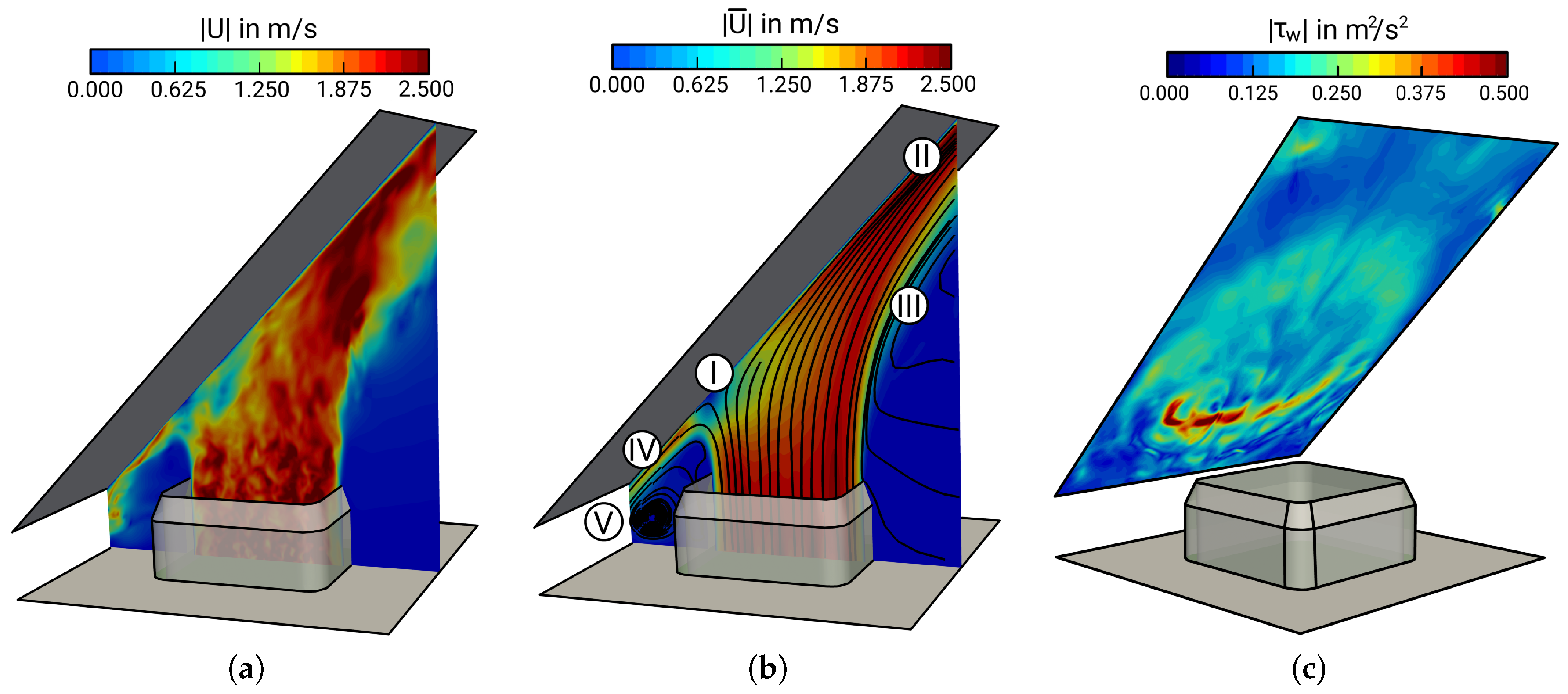
Before analyzing the thermal transport and entropy mechanisms in the 45 -inclined jet impinging on a heated surface, relevant results from the previous study of isothermal fluid flow in the same configuration [59] are briefly summarized. Notice that impressive agreements have been reported between the numerical results and available experimental data for the flow field. Focusing on numerical results, Figure 2 shows: (a) a contour plot of the instantaneous magnitude velocity | U | at the mid-plane section; (b) time-averaged magnitude velocity | U ¯ | at the mid-plane section with superimposed streamlines of mean velocity; and (c) instantaneous values of absolute shear stresses | τ w | at the impinged wall.
It can be seen in Figure 2a that the generated turbulent air stream leaves the square nozzle, impinges on the plate and is divided into two characteristic wall-jets directed outward along the heated plate. Thereby, due to the turbulence generating grid inside the nozzle, the flow appears highly turbulent (turbulence intensity of ∼10%) and not fully developed when it leaves the nozzle exit section. As is apparent in Figure 2b, five main regions with distinctive flow features can be distinguished in the inclined impinging jet configuration, namely: (I) the stagnation point that is shifted away half a diameter from the geometric center of the jet origin towards the compression side; (II) the wall-jet in the main flow direction, where the flow is predominantly parallel to the wall; (III) the shear layer region on the side away from the impinged wall, which is triggered by the interaction of the jet with the ambient fluid; (IV) the opposed wall-jet region, where the fluid is subject to a strong acceleration and stretching; and (V) the recirculation zone enclosed by the compression side of the impinged plate, the nozzle wall and the lower confined surface. With regard to flow/wall interaction processes (see Figure 2c), wall shear stresses are very low at the stagnation point, peak in its immediate vicinity and tend to smear out in the main flow direction. Thereby, | τ w | is primarily concentrated at the secondary opposed wall-jet region, where the direction of the flow changes suddenly. Furthermore, it was found that: (1) production of turbulent kinetic energy appears negative at the stagnation point; (2) quasi-coherent thin streaks with isolated stretched nests of concentrated vorticity and large characteristic time scales appear around the stagnation point; and (3) the organization of the flow is predominantly toroidal further downstream at the wall-jet region in the main flow direction.
It is evident from the observations of the previous study [59], that the inclined impinging jet features very complex fluid flow dynamics and is characterized by strong flow/wall interaction processes. The influence of this subtle flow dynamics on the thermal transport and entropy production mechanisms in non-isothermal impinging flows is explored in the present paper.

4. Near-Wall Thermal Characteristics

At first, the achieved results of mean and root-mean square (RMS) temperatures in the vicinity of the wall are presented and discussed. Then, budget terms of the temperature variance transport equation are examined to identify and quantify turbulent heat transport phenomena that are not directly described by means of first or second order moments of temperature. Subsequently, heat fluxes within the thermal boundary layer are presented, and deviations from isotropic behavior are pointed out. Finally, Nusselt numbers are provided to complement the DNS database of near-wall thermal statistics.
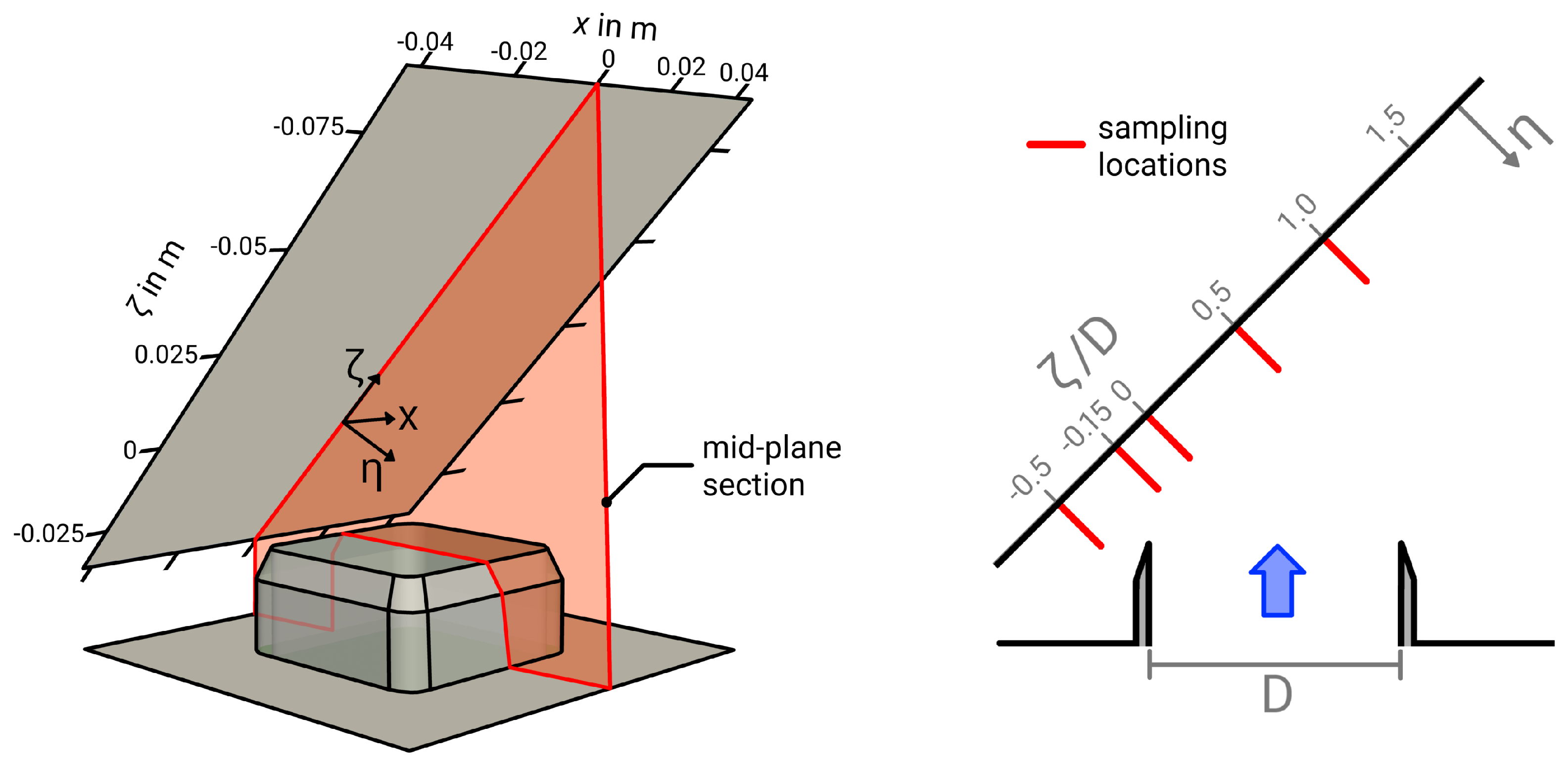
Results in this study are presented at the mid-plane section ( x / D = 0 ) for different wall-normal traverses ( ζ / D = 0.5 , 0.15 , 0 , 0.5 , 1 ). The corresponding sampling locations are depicted in Figure 3. Notice that an additional coordinate system is introduced with η representing the wall-normal direction, and ζ is the direction along the wall with the origin located at the stagnation point.

4.1. First and Second Order Thermal Moments

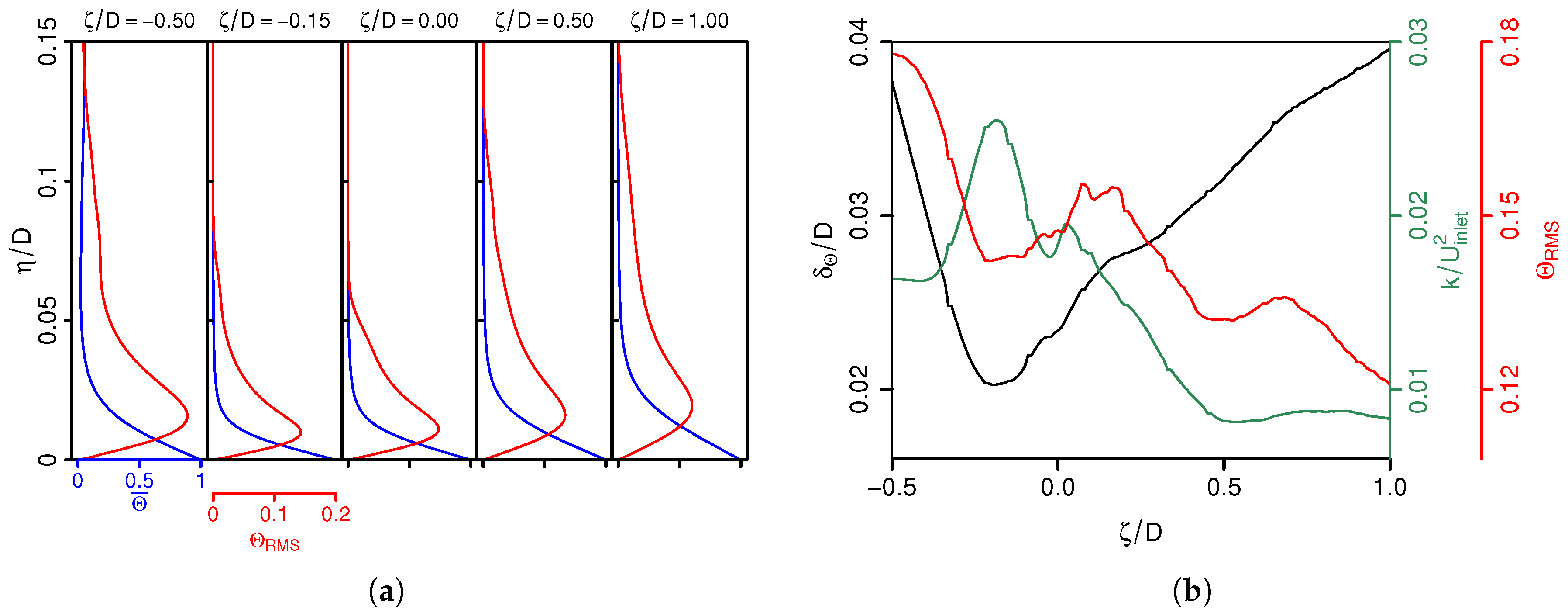
Figure 4a shows the normalized mean and RMS temperature ( Θ ¯ and Θ R M S ) profiles along the wall normal direction η / D , where the non-dimensional temperature is defined as Θ = ( T T i n l e t ) / ( T w a l l T i n l e t ) . The corresponding thermal boundary layer thickness δ Θ and the evolution of peak values of turbulent kinetic energy k and Θ R M S along the wall parallel direction ζ / D are depicted in Figure 4b, where δ Θ is defined as the distance to the wall with Θ ( η / D = δ Θ ) = 0.05.
As expected, mean temperatures are high at the wall and decrease rapidly with increasing distance to the wall (see blue lines in Figure 4a). Surprisingly, steepest wall-normal temperature gradients associated with intense heat transfer occur at ζ / D = 0.15 and not directly at the stagnation point, as is usually the case in jets impinging normally on a heated surface (for a comparison, see, e.g., [36]). Away from ζ / D = 0.15 , temperature profiles enlarge, while at the same time, gradients tend to smear out. Regarding temperature fluctuations (red lines in Figure 4a), high values of Θ R M S are concentrated in the near-wall region with strong peaks situated close to the wall, closest at ζ / D = 0.15 . In line with the mean temperature, profiles of Θ R M S spread away from ζ / D = 0.15 , while peak values become shifted away from the wall. The peculiar behavior of this location for the thermal transport within the 45 -inclined impinging jet configuration becomes clearer by examining the variations of thermal boundary layer thickness δ Θ and the evolution of peak values of k and Θ R M S along the wall parallel direction in Figure 4b. Here, it can be seen that the minimum of δ Θ appears not directly at the stagnation point as is usually the case in jets impinging normally on a heated surface. Instead, the minimum of δ Θ is slightly shifted towards the compression side at ζ / D 0.15 and increases rapidly away from it. Thereby, it is interesting to observe that the minimum of δ Θ coincides with the peak value of k and with a local minimum of Θ R M S . Obviously, turbulence-induced mixing among other thermofluid processes enhances the heat transfer at ζ / D 0.15 , resulting in a thinning of the thermal boundary layer, which is significantly thinner than at the stagnation point where k exhibits a local minimum.

4.2. Turbulent Thermal Processes

After examining mean temperature and variances, turbulent thermal transport phenomena close to the impinged wall are subsequently analyzed in this section. For this purpose, the evolution of temperature variance is investigated in order to identify and quantify turbulent thermal transport processes that are not directly described by means of first or second order moments of temperature. In the case of constant density fluid flow with convective passive heat transfer, as is assumed in this work, the equation for the evolution of the temperature variance T 2 ¯ can be written as [74]:
T 2 ¯ t + U i ¯ T 2 ¯ x i = 2 U i T ¯ T ¯ x i P T 2 ¯ 2 ν P r T x i T x i ¯ ϵ T 2 ¯ + ν P r 2 T 2 ¯ x i 2 D T 2 ¯ x i U i T 2 ¯ Π T 2 ¯ .
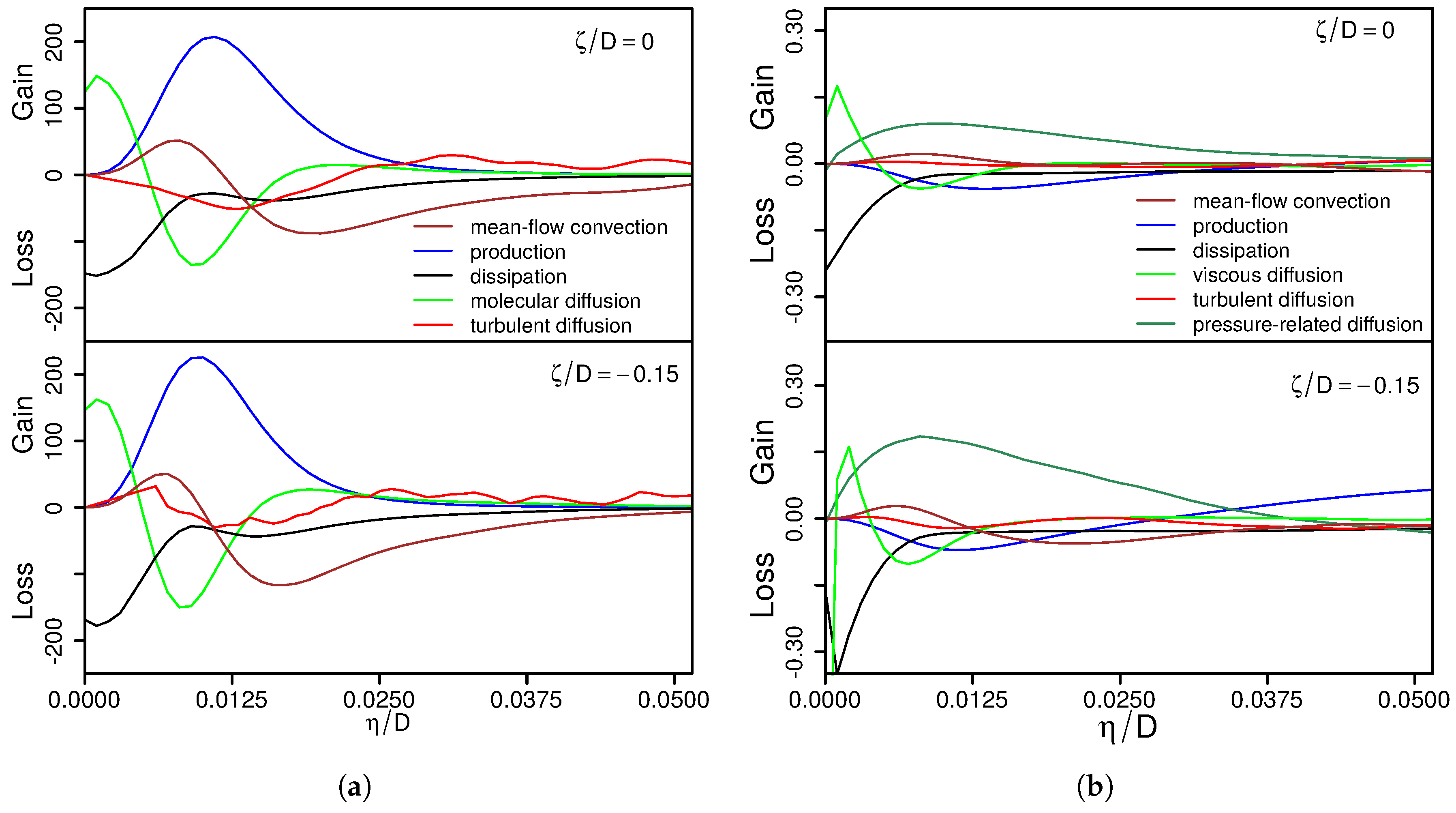
The first and second terms on the left-hand side denote the local change and mean-flow convection of T 2 ¯ , respectively; P T 2 ¯ represents the production, ϵ T 2 ¯ the dissipation, D T 2 ¯ the molecular diffusion and Π T 2 ¯ the turbulent diffusion of temperature variance. Figure 5a shows profiles of normalized budget terms of T 2 ¯ at the stagnation point ( ζ / D = 0 ) and at the location of the smallest thermal boundary layer ( ζ / D = 0.15 ). For comparison, the corresponding source and sink terms of turbulent kinetic energy transport are depicted in Figure 5b, with budget terms of temperature variance normalized by U i n l e t T w a l l T i n l e t 2 / D and budget terms of turbulent kinetic energy by U i n l e t 3 / D .
Regarding budget terms of T 2 ¯ as shown in Figure 5a, the production, dissipation, molecular diffusion and mean-flow convection are the dominant terms, while turbulent diffusion is relatively small. At the edge of the thermal boundary layer ( η / D = δ Θ / D 0.02 ), negative mean-flow convection dominates and transports excess temperature variance towards the wall. Closer to the wall, the production term exhibits a strong peak situated approximately at half the thermal boundary layer thickness where Θ R M S is maximal, as well (see Figure 4b). Thereby, mean-flow convection becomes positive, and the production is predominantly balanced by negative molecular diffusion and not by dissipation as is usually the case in turbulent heat transfer in channel flows or round jets (see, e.g., [75,76]). Immediately adjacent to the wall, production, turbulent diffusion and mean-flow convection vanish, and only molecular diffusion contributes to balance the high dissipation term. A comparison of budget terms of temperature variance at ζ / D = 0.0 and ζ / D = 0.15 shows that the contributions of mean-flow convection and molecular diffusion are slightly higher at ζ / D = 0.15 , which allows one to explain the smaller temperature variance in this region. However, by and large, both balances of the contributions are quite similar, and consequently, the overall physics of turbulent thermal transport behave similar in both regions.
In contrast to the budget of temperature variance, the balances of the turbulent kinetic energy in Figure 5b differ significantly from each other. At both ζ / D = 0 and ζ / D = 0.15 , the production is negative in the vicinity of the wall, which is balanced by pressure-related diffusion of k rather than viscous dissipation. Thereby, it can be seen that pressure-related diffusion and mean-flow convection are considerably higher at ζ / D = 0.015 . It is therefore most likely that the vigorous turbulent activity at ζ / D = 0.15 is predominantly caused by pressure-related diffusion and mean-flow convection processes. Another noticeable difference is the high amount of production outside the boundary layer ( η / D > 0.03 ) only apparent at ζ / D = 0.015 , which suggests that turbulence is to some extent also induced by the free-stream.
To summarize, based on the analysis of the budget terms of T 2 ¯ and k, it appears that turbulent thermal and fluid flow transport processes around the stagnation point of the inclined impinging jet configuration are considerably different from those found in turbulent heated channel flows or round jets. In contrast to other wall-bounded flows, dissipation is relatively small, while in the case of T 2 ¯ -transport and in the case of k-transport, molecular diffusion and pressure-related diffusion dominate, respectively. Both terms are noticeably higher at ζ / D = 0.15 than at the stagnation point, which might help to explain the higher value of k and the smaller amount of T 2 ¯ at ζ / D = 0.15 .

4.3. Heat Transport

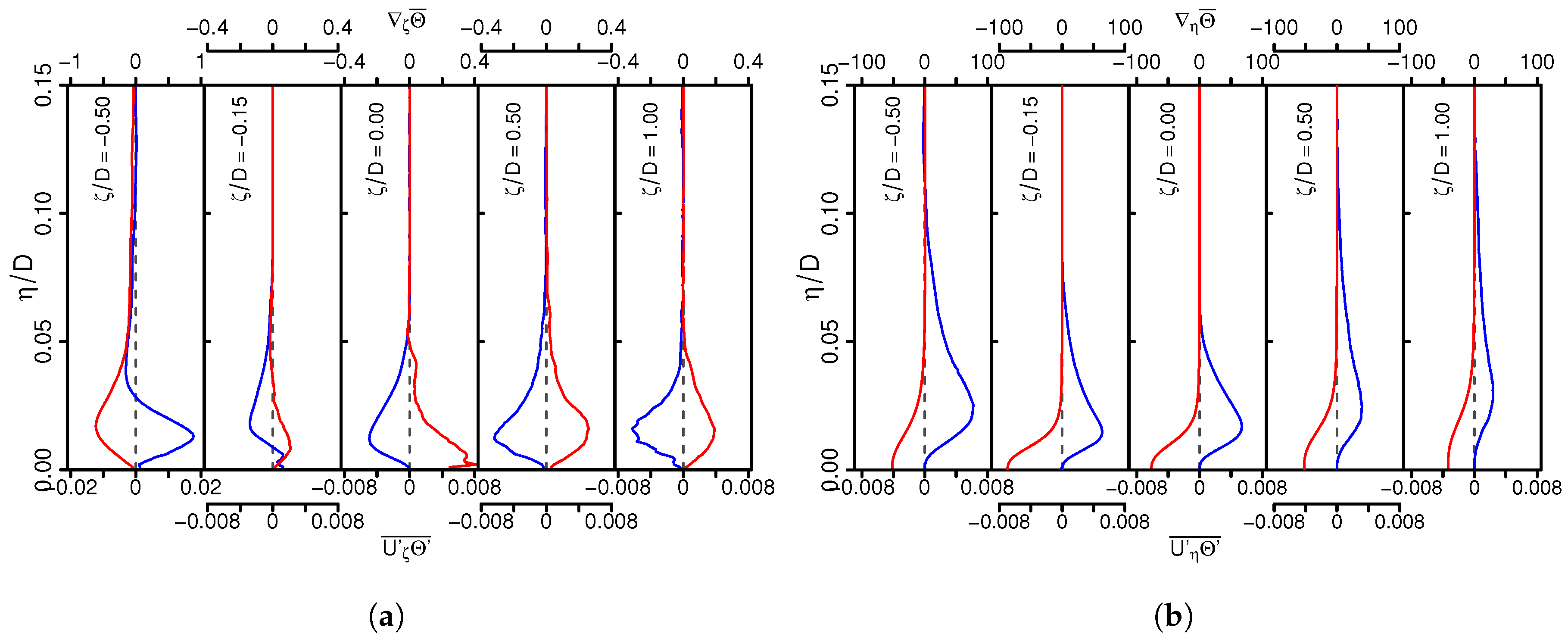
Next, turbulent heat fluxes U i Θ ¯ and mean temperature gradients i Θ ¯ in the vicinity of the impinged wall are examined. Profiles of wall-parallel and wall-normal components of U i Θ ¯ and i Θ ¯ are plotted in Figure 6a,b, respectively.
Concerning turbulent heat fluxes, values of U ζ Θ ¯ and U η Θ ¯ are large at the opposed wall-jet region ( ζ / D = 0.5 ) and considerably smaller away from it. Thereby, values of wall-normal gradients η Θ ¯ are significantly larger than wall-parallel ones ζ Θ ¯ , even though the corresponding heat flux components are of the same order of magnitude. This is most notable at ζ / D = 0.15 and at the stagnation point ( ζ / D = 0 ). Therefore, heat transport in the inclined impinging jet configuration is primarily directed normal to the wall and only qualitatively aligned with mean temperature gradients. This is in good agreement with observations in fully-developed jets impinging normally on a heated surface (see, e.g., [36]), which also holds for impinging flows that impinge at a particular angle of 45 . In addition, it is interesting to observe that close to the wall at ζ / D = 0.15 and in the free-stream at ζ / D = 0.5 , heat is transported counter the gradient from low to high temperature regions. As pointed out by Schumann [77], the reason for such a paradoxical behavior arises in flows if the dissipation of temperature fluctuations is too small to balance diffusional sources, while turbulence intensity is large and T 2 ¯ is small. Both, low dissipation of temperature fluctuations, as well as vigorous turbulent intensity and small values of T 2 ¯ are observed in the present study in regions where counter gradient heat flux takes place (see Section 4.1 and Section 4.2).
The observation that wall-normal temperature gradients are several times larger than wall-parallel ones and the occurrence of counter gradient heat flux within the inclined impinging jet configuration warrants a closer examination of turbulent heat fluxes. With regard to turbulent heat flux modeling in RANS and LES of jet impingement heat transfer, most often, linear eddy diffusivity models are applied in the literature (see, e.g., [36,45,66,67]). The linear eddy diffusivity hypothesis reads:
U i Θ ¯ = α t i Θ ¯ .
Thereby, it is assumed that the turbulent heat fluxes are aligned with the corresponding mean/filtered temperature gradient, with turbulent/subgrid heat diffusivity α t as a proportional positive scalar factor. This assumption is examined in Figure 7a in the context of RANS modeling within the thermal boundary layer of the impinging jet ( 0 < η / δ Θ < 1 ). Exemplarily, results are depicted at both the wall-jet region ( ζ / D = 0.5 ), the location of minimal boundary layer thickness ( ζ / D = 0.15 ), the stagnation point ( ζ / D = 0 ) and at the boundary layer region ( ζ / D = 1 ). Thereby, the deviation from isotropic heat flux is represented by plotting U ζ Θ ¯ η Θ ¯ against U η Θ ¯ ζ Θ ¯ . Both quantities are equal in the case of isotropic heat flux, which is illustrated by a black dotted line in the graph. Regions where heat is transported counter the gradient from low to high temperature regions are highlighted in gray.
It can be clearly seen in Figure 7a that heat fluxes are predominantly isotropic very close to the wall, become considerably anisotropic with increasing wall distance and finally return back to the isotropic state for η / δ Θ > 0.8 . This holds more or less for all regions under consideration. Additionally, it can be observed that heat fluxes behave most anisotropic at the wall-jet region, while they turn back to the isotropic state with increasing ζ / D , but do not reach fully-isotropic behavior. Further, it appears that counter gradient heat flux takes place close to the wall at ζ / D = 0.15 , as well as in the free-stream at ζ / D = 0.5 , which is in line with the observations in Figure 6a. Both counter gradient heat flux and the inherently anisotropic nature of heat fluxes within the thermal boundary layer of the inclined impinging jet suggest that tensorial heat diffusivity models as proposed in [78,79,80,81,82] might be suitable for such kinds of flows.
To complete the discussion of turbulent heat transport modeling within the inclined impinging jet configuration, Figure 7b shows the ratio of mechanical ( τ = k / ϵ ) and thermal time scales ( τ θ = T 2 ¯ / ϵ T 2 ¯ ) along the wall-parallel direction at a wall distance of η = 0.5 δ Θ . This characteristic time-scale ratio is of particular importance for the heat transport description and is usually close to 0.5 in equilibrium thermal boundary layers (see, e.g., [83]). Clearly, from Figure 7b, τ / τ θ varies strongly along ζ / D and deviates considerably from the equilibrium value of τ / τ θ = 0.5 . In particular, at ζ / D = 0.15 , the time-scale ratio exceeded 1.5, indicating strong non-equilibrium effects in heat and fluid flow transport. This is in good agreement with the earlier observation in Section 4.2 that dissipation is relatively small and diffusion processes dominate the turbulent heat transport at ζ / D = 0.15 .

4.4. Wall Heat Transfer

Finally, heat transfer from the target plate to the fluid is examined by means of the local Nusselt number, defined as:
N u = h t D λ = T η | η = 0 D T w T i n l e t ,
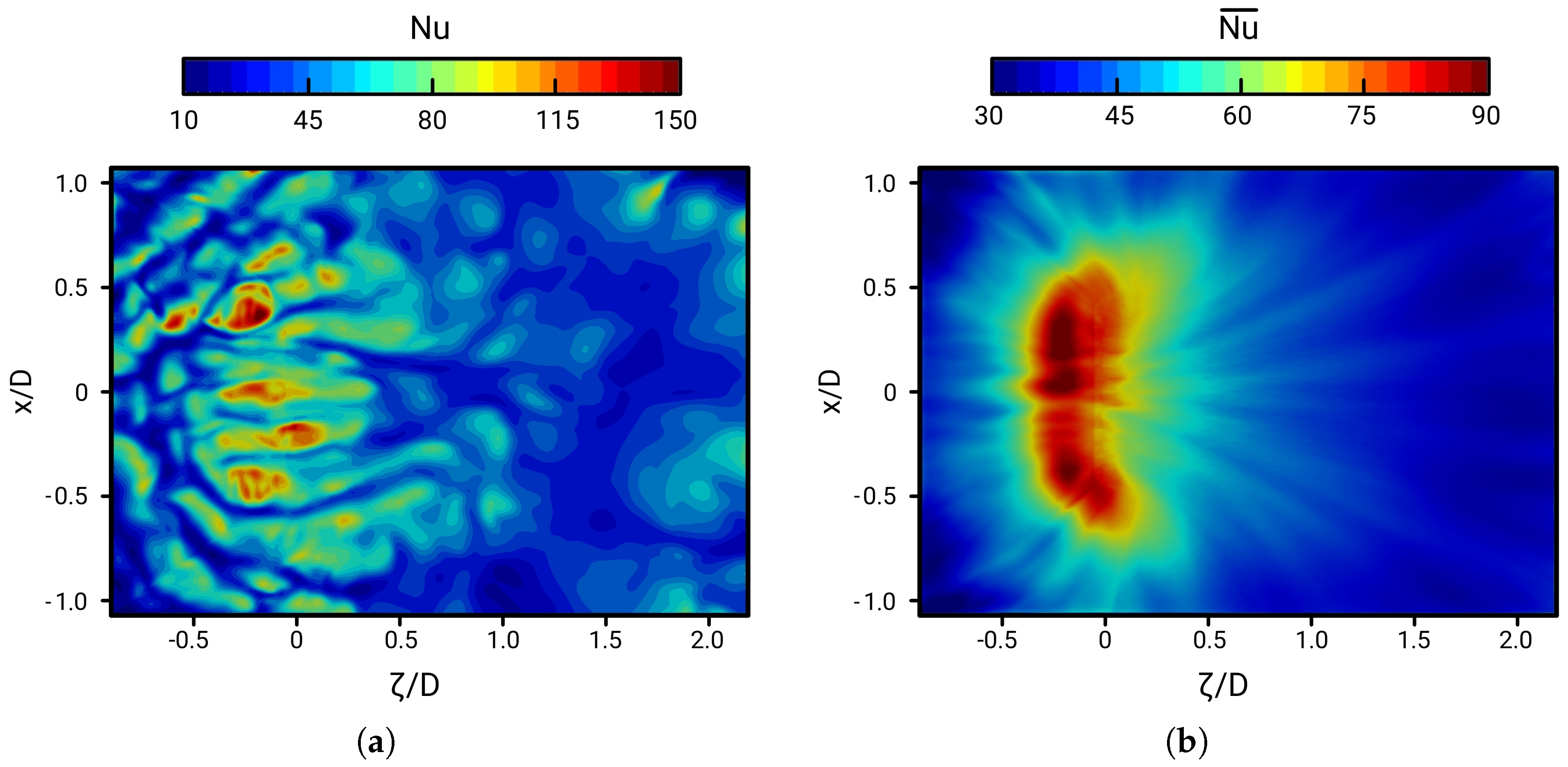
where h t is the heat transfer coefficient and λ the thermal conductivity. Figure 8 shows the instantaneous (a) and time-averaged (b) local Nusselt Number at the impinged wall.
Just as in the case of fully-developed jets impinging normally on a heated surface (see, e.g., [36]), high values of instantaneous Nusselt numbers associated with large-scale eddy structures are concentrated around the stagnation point. However, as might be seen in Figure 8a, peak values are not directly situated at the stagnation point; instead, they are slightly shifted towards the opposed wall-jet region ( ζ / D 0.15 ). A similar pattern is found for mean Nu numbers in Figure 8b. Thereby, the highest values of Nu appear at ζ / D 0.15 in the range of 0.2 < x / D < 0.2 . Away from this region, Nu numbers decrease rapidly. This is in good agreement with the finding in Section 4.3, pointing out that the wall-normal temperature gradients are very steep at ζ / D 0.15 associated with high heat transfer.
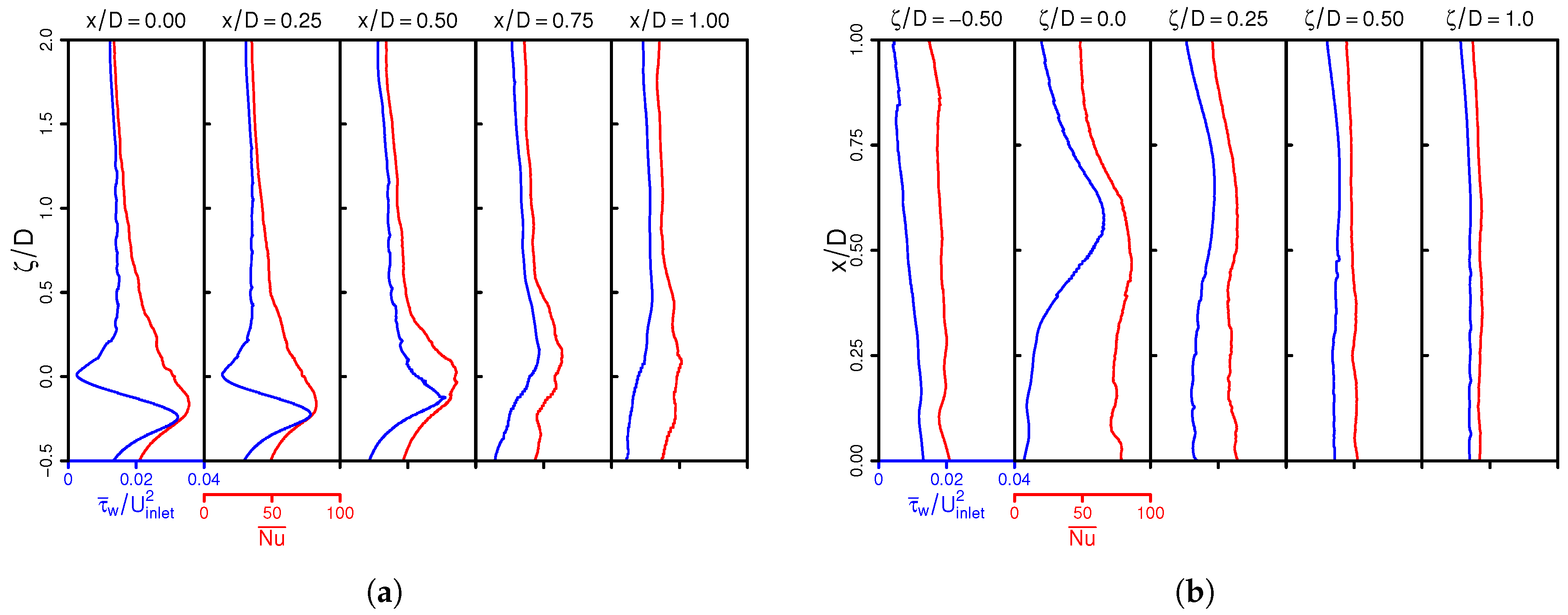
To complete the DNS database of near-wall thermal statistics, profiles of time-averaged Nu numbers are provided in Figure 9a,b in the span-wise and wall-parallel direction, respectively. Supplementary profiles of the wall shear stress are included to highlight the correlation of heat and fluid flow in the vicinity of the wall. Both datasets might be of particular interest for validation purpose for near-wall modeling strategies of heat and fluid flow in the context of both LES and RANS.

5. Entropy Generation Mechanisms

In this section, entropy generation processes are analyzed to identify and quantify the causes of irreversibilities evolving in such impinging cooling arrangements. In order to display irreversibilities within the 45 -inclined impinging jet configuration, the second law of thermodynamics is applied in this work in the form of local entropy imbalance at the continuum mechanical level (see, e.g., [63,65,84]). Notice that the term “irreversibility” in the present paper is understood as the “one-sidedness” of time of a physical process in contrast to processes for which the dynamics remain unchanged when the sequence of time is reversed (time-reversible process) in accordance with [85]. For such processes, the entropy production rate is usually accepted to serve as the measure of the irreversibility. Of course, other measures are now being introduced, like entransy and its dissipation rate, which also can be used as a measure of irreversibility, especially related to the heat conduction problem without the conversion between heat and work (see [86]).
In this work, we rely on the entropy production for its wide applicability once complex processes including friction, heat transfer across a finite temperature gradient, inelastic deformation of solids, unrestrained expansion, mixing of fluids, chemical reactions, etc., are involved. Assuming a Navier–Stokes–Fourier fluid flow with convective heat transport, no external body force and constant physical properties, the entropy inequality reads:
ρ s t + ρ U i s x j + x i q i T = ρ ν T U i x j + U j x i U i x j Π v + λ T 2 T x j T x j Π q 0 .
The terms on the left-hand side denote the local change, the convection and the flux of entropy density s (from left to right). Π v and Π q represent the entropy production terms by viscous dissipation and by heat conduction, respectively, and both are responsible for irreversibilities evolving in such a thermo-viscous fluid flow. Thereby, it is assumed that Π v and Π q in the inequality (7) are locally never negative, and the entropy imbalance holds for any thermodynamical process.
In the case of turbulent Navier–Stokes–Fourier fluid flow, it is useful to split Π v and Π q into time-mean and fluctuation parts in order to display entropy production by mean and turbulent quantities, respectively. This leads to:
Π ¯ v = ρ ¯ ν ¯ T ¯ U ¯ i x j + U ¯ j x i U ¯ i x j Π ¯ v m + ρ ν T U i x j + U j x i U i x j ¯ ρ ¯ ν ¯ T ¯ U ¯ i x j + U ¯ j x i U ¯ i x j Π ¯ v t
for the entropy production due to viscous dissipation. A similar expression can be derived for the entropy production due to heat conduction as:
Π ¯ q = λ ¯ T ¯ 2 T ¯ x j T ¯ x j Π ¯ q m + λ T 2 T x j T x j ¯ λ ¯ T ¯ 2 T ¯ x j T ¯ x j Π ¯ q t .
Here, the terms Π ¯ v m and Π ¯ q m represent entropy production due to mean gradients, while Π ¯ v t and Π ¯ q t are due to fluctuating gradients.
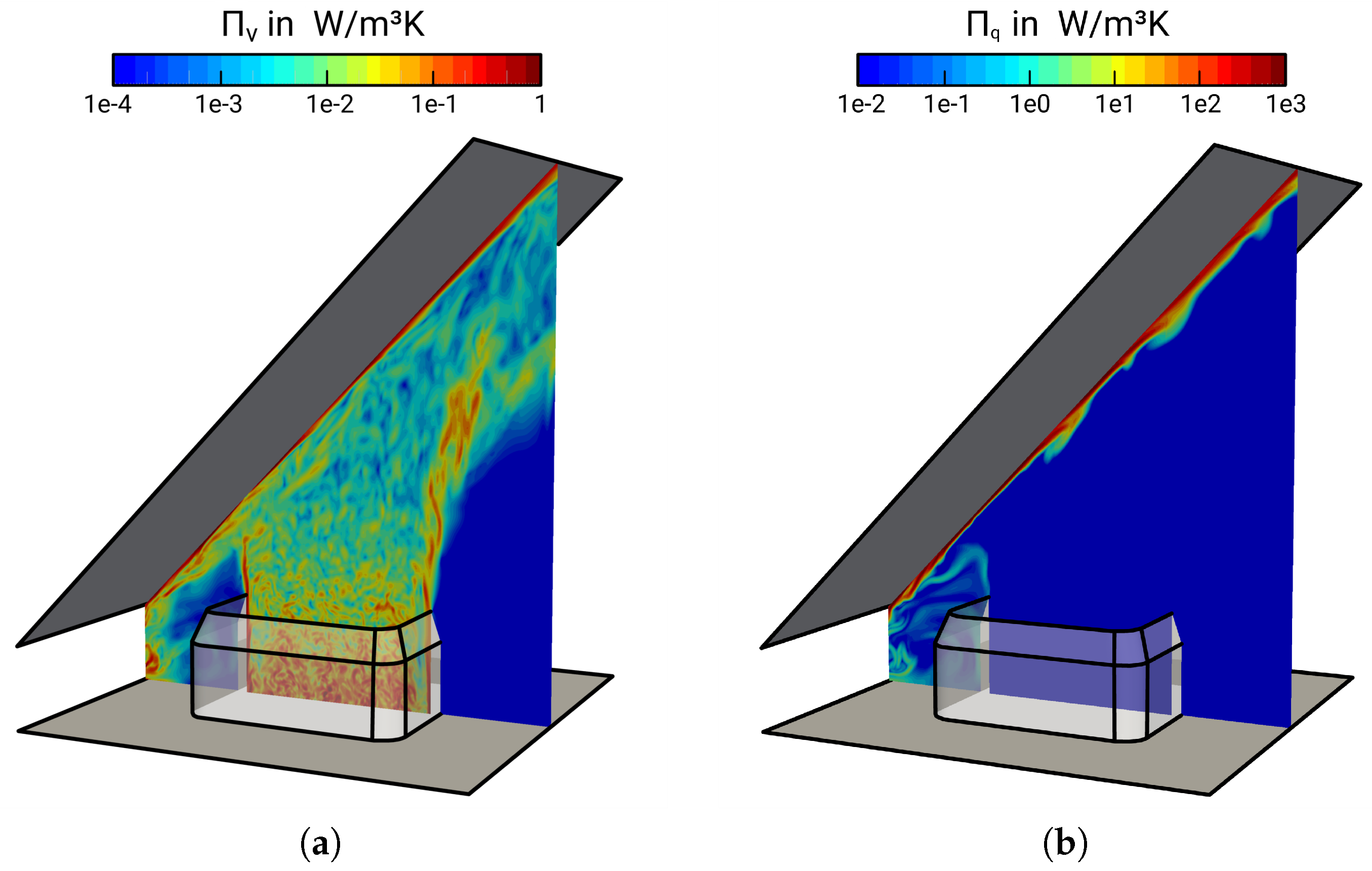
Starting with the instantaneous entropy generation, Figure 10 depicts snapshots of entropy production rates related to (a) viscous dissipation and (b) heat conduction. In order to visualize the wide range of entropy generating scales evolving in the 45 -inclined impinging jet configuration, a logarithmic color range is used.
Focusing on the instantaneous entropy generation rates by viscous dissipation (see Figure 10a), it appears that the entropy is predominantly produced downstream the perforated plate located inside the nozzle, at the jets’ shear layer and especially in the vicinity of the impinged wall due to a large contribution of shear-induced turbulence mixing in these regions. Thereby, large coherent streaks with high values of Π v are generated at the mixing layers that are carried along by the flow and dissolve while they cascade into smaller ones. At the jets’ core, the entropy production is small and decreases in the main flow direction. In contrast, entropy production rates by heat conduction are primarily concentrated at the impinged wall; see Figure 10b. This seems reasonable because of the extreme non-uniformity of the temperature field resulting in steep gradients in this region. Apart from the wall, entropy is also produced at the recirculation zone on the compression side of the impinging jet due to heat transport, where hot fluid is separated from the heated wall and transported back to the jets’ shear layer, inducing temperature gradients. By comparing Figure 10a,b, it is apparent that scales of Π q are considerably larger than those of Π v . This makes clear that irreversibilities evolving in such impinging cooling arrangements occur at different scales, predominantly on large-scale structures in the case of heat transport and over a wide range of scales in the case of viscous dissipation.
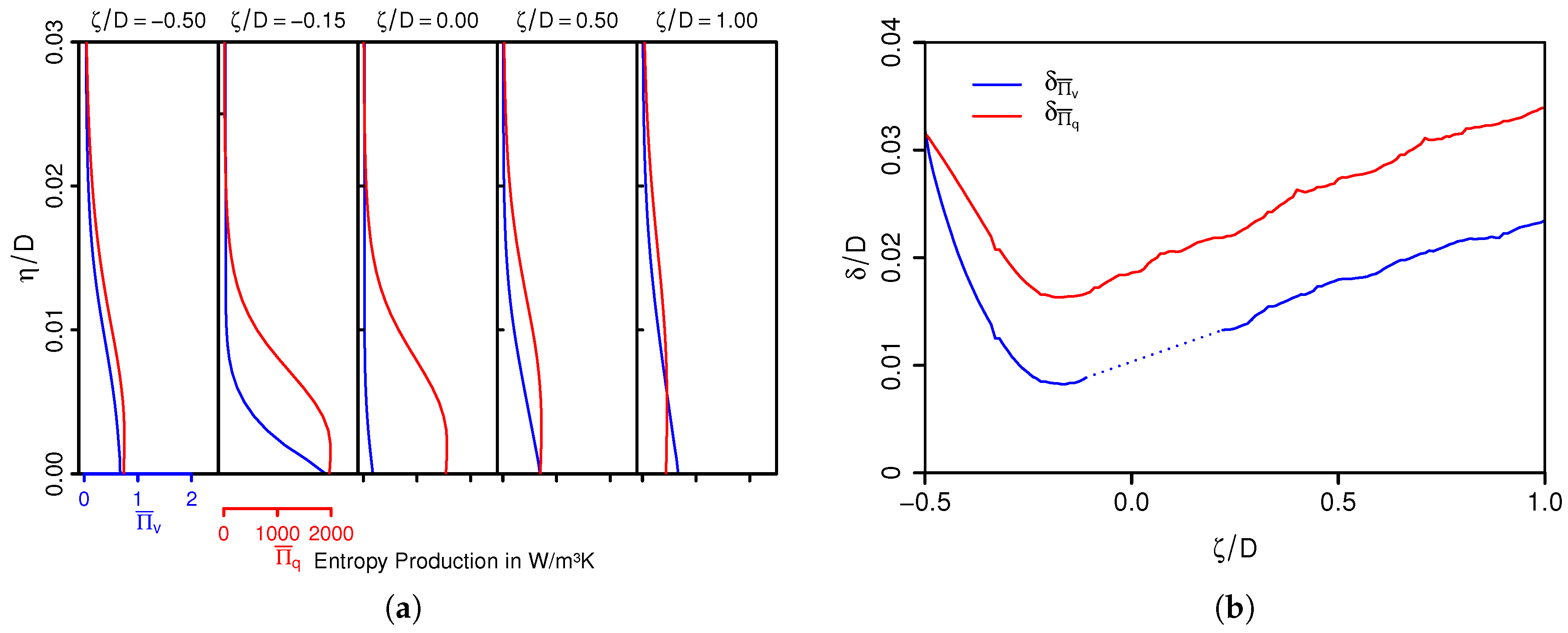
From a qualitative point of view, it appears especially that the heated wall acts as a strong source of irreversibility within impinging cooling arrangements for both entropy production due to viscous dissipation and heat conduction. This observation is quantified next by means of time-averaged rates of entropy production in the vicinity of the impinged wall. Figure 11a shows the time-averaged rates of entropy production by viscous dissipation Π ¯ v and by heat transport Π ¯ q as a function of non-dimensional wall distance η / D . Variations of the entropy production boundary layer thicknesses δ Π ¯ v and δ Π ¯ q are depicted in Figure 11b, where δ Π ¯ v is defined as the distance to the wall with Π ¯ v ( η / D = δ Π ¯ v ) = 0.05 Π ¯ v ( η / D = 0 ) and in the case of δ Π ¯ q as Π ¯ q ( η / D = δ Π ¯ q ) = 0.05 Π ¯ q ( η / D = 0 ) . Notice that values δ Π ¯ v at the immediate vicinity of the stagnation point are omitted because Π ¯ v is inherently very small in this region.
Both Π ¯ v and Π ¯ q are high in the vicinity of the wall and decrease rapidly away from it. In line with the observation made in Section 4 that thermal and fluid flow transport processes are predominantly limited to the near-wall region, it turns out clearly that these transport processes are essentially irreversible, especially at ζ / D = 0.15 . This holds more or less for the entire range from ζ / d = 0.5 up to ζ / d = 1 , excluding the stagnation point. Here, values of Π ¯ v are relatively small because of the absence of shearing, while at the same time, the heat transfer along with Π ¯ q are intense. Obviously, irreversible fluid flow transport processes hardly have any influence on the heat transport at the stagnation point, in contrast to the near-wall region elsewhere. In addition, it is interesting to notice in Figure 11b that irreversible fluid flow transport processes occur much closer to the wall than irreversible heat transport processes ( δ Π ¯ v / δ Π ¯ q ranging from 0.5–0.9). This might be due to the small molecular Prandtl number in the present study ( P r = 0.7 ), which implies that the thermal diffusivity process dominates the momentum diffusivity, yielding a smaller momentum boundary layer thickness and consequently a smaller boundary layer thickness of Π ¯ v compared with δ Π ¯ q .
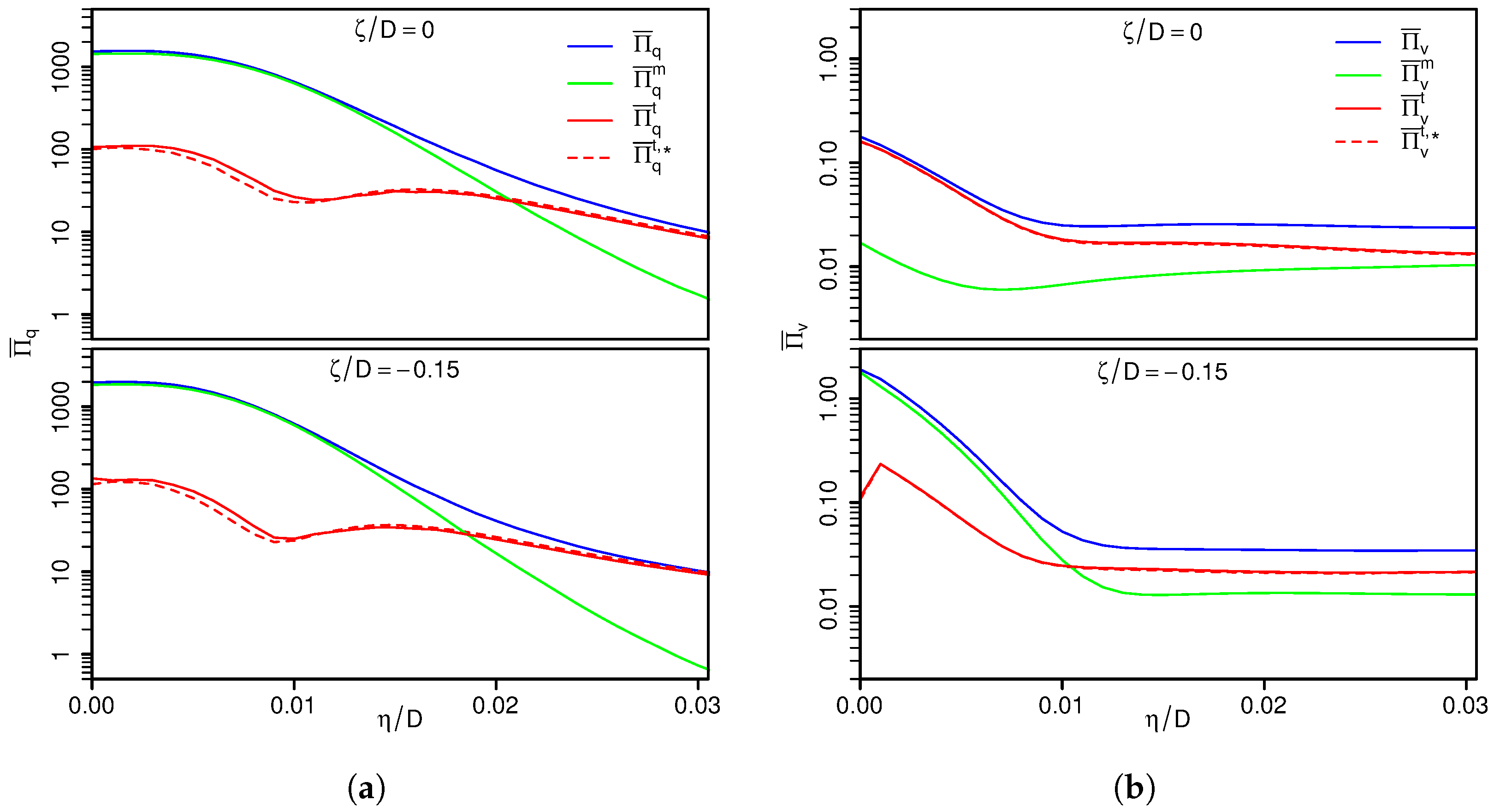
To complete the analysis of irreversible processes for the 45 -inclined impinging jet configuration, time-mean and turbulent parts of entropy production rates due to viscous dissipation ( Π v m and Π v t ) and to heat conduction ( Π q m and Π q t ) are depicted in Figure 12a,b, respectively. Results are exclusively shown for the stagnation point ( ζ / D = 0 ) and at ζ / D = 0.15 , in which a semi-logarithmic scale is used in order to distinguish between high entropy production rates at the near-wall region and low values in the free-stream. In addition, estimations for the turbulent parts of entropy production rates based on the turbulence dissipation rates are plotted in Figure 12 (dashed red lines). Such estimations are commonly applied in second law analyses within the RANS context (see, e.g., [87]). They read:
Π v t , * = ρ ¯ T ¯ ϵ k and Π q t , * = 1 2 ρ ¯ c ¯ p T ¯ 2 ϵ T 2 ¯ ,
where ϵ k is the dissipation rate of the turbulence kinetic energy, ϵ T 2 ¯ the dissipation rate of the temperature variance and c p the isobaric heat capacity. In these formulations, it is assumed that temperature fluctuations in the denominator, 1 / T and 1 / T 2 , respectively, are negligible [87].
As is apparent from Figure 12, the entropy generation in the vicinity of the wall is predominantly caused by mean gradients rather than by turbulence processes. Further away from the wall, Π v m and Π q m decrease, and the entropy production related to fluctuating gradients ( Π v t and Π q t ) dominates. By comparing entropy production rates at ζ / D = 0 and ζ / D = 0.15 , the contributions of entropy generated by heat conduction are very similar at both locations. This holds also true for Π v , excluding Π v m , which is considerably larger at ζ / D = 0.15 compared to the value at the stagnation point. Regarding the turbulent part of entropy production rates estimated by means of turbulence dissipation rates, Π v t , * and Π q t , * in Figure 12, it can be clearly seen that the predictions obtained by the estimations (see Equation (10)) are very close to the profiles calculated directly from Equations (8)–(9), respectively. This confirms that the formulations in Equation (10) are appropriate to describe the entropy generation due to fluctuating gradients, at least for the 45 -inclined impinging jet configuration. However, it should be noted here that the prediction accuracy of the estimation (10) strongly depends on an accurate description of ϵ k and ϵ T 2 ¯ in both the RANS and LES context, particularly in the vicinity of the wall.
To sum up the main findings of the second law analysis, this study reveals that irreversibilities evolving in impinging cooling arrangements occur at different scales, predominantly on large-scale structures regarding heat transport and over a wide range of scales in the case of entropy production related to viscous dissipation. Especially the heated wall acts as a strong source of irreversibility for both, entropy production related to viscous dissipation and heat conduction. Thereby, the entropy production from the mean gradients is much higher than that of fluctuating gradients. In addition, irreversible laminar fluid flow transport processes hardly have any influence on the heat transport at the stagnation point, while their influence is high in other near-wall regions. From an engineering standpoint, these findings particularly imply that the design of the impinged plate (surface roughness, corrugation, chevron angle, etc.) is very important for efficient use of energy in such thermal arrangements.

6. Concluding Remarks

Direct numerical simulation of turbulent fluid flow with convective heat transport of a non-fully-developed jet impinging on a 45 -inclined heated plate at a moderate Reynolds number, but high turbulent intensity has been conducted. Thereby, thermal transport and entropy generation mechanisms have been investigated, and a comprehensive dataset of near-wall thermal statistics and local entropy production rates was provided. This comprehensive dataset includes first and second order thermal moments, budget terms in the temperature variance equation, turbulent heat fluxes, mechanical and thermal time scales, local Nusselt numbers and local entropy production rates related to both viscous dissipation and heat transport. Such a dataset is difficult to obtain experimentally, especially in the vicinity of the wall, and will be particularly useful for validation purposes of near-wall modeling approaches in the context of LES and RANS.
Some important observations from this study concerning impingement cooling, thermal processes, causes of irreversibilities and suggested modeling strategies regarding LES and RANS can be outlined as following:
I 
Examining near-wall thermal statistics within the 45 -inclined impinging jet configuration, it turned out that the peak heat transfer does not appear directly at the stagnation point as is usually the case in jets impinging normally on a heated surface. Instead, the highest Nusselt numbers, the minimum of thermal boundary layer thickness and largest wall-normal heat transport are slightly shifted towards the compression side of the inclined jet ( ζ / D = 0 . 15 ). Thereby, turbulent intensity is high, while temperature variance exhibits a local minimum at this location.
II 
Based on the analysis of the budget contributions of different terms in the temperature variance and turbulence kinetic energy equations, it appears that turbulent thermal and fluid flow transport processes around the stagnation point of the inclined impinging jet are considerably different from those found in other wall-bounded flows. Dissipation is relatively small, while molecular and pressure-related diffusion dominate. In the case of turbulent kinetic energy, the production term is prevailing negative.
III 
It is observed that heat is transported counter to the gradient from low to high temperature regions at the location of maximal heat transfer ( ζ / D = 0 . 15 ). The reason for such a paradoxical behavior is that the dissipation of temperature fluctuations is too small to balance the diffusional sources (see also [77]).
IV 
Regarding turbulent heat transport, it turned out that fluxes are predominantly isotropic very close to the wall, become highly anisotropic with increasing wall distance and finally return to the isotropic state at the edge of the thermal boundary layer. Furthermore, the heat fluxes behave most anisotropically on the compression side. Both, the counter gradient heat flux and the inherently anisotropic nature of heat fluxes in the thermal boundary layer of the inclined impinging jet suggest that tensorial heat diffusivity models might be appropriate for such kinds of thermo-viscous flows, especially in the context of RANS.
V 
The ratio of mechanical τ and thermal time scales τ θ deviates considerably from the equilibrium value of τ / τ θ = 0 . 5 in the thermal boundary layer of the inclined impinging jet. In particular around the stagnation point, the time-scale ratio exceeded 1.5, indicating strong non-equilibrium effects in heat and fluid flow transport.
VI 
Especially the heated wall acts as a strong source of reversibility in the case of impinging cooling arrangements. This holds for both entropy production due to viscous dissipation and heat conduction. Thereby, the entropy production contribution of mean gradients dominates that of the fluctuating gradients. This suggests that the design of the impinged plate (surface roughness, corrugation, chevron angle, etc.) is particularly important for efficient use of energy in such thermal arrangements that may exhibit intensification of turbulence in the vicinity of the wall.
VII 
Regarding the conceptional engineering design of such thermal devices, this study confirms that the estimation of the turbulent part of the entropy production based on turbulence dissipation rates in non-reacting, non-isothermal fluid flows represents a reliable approximation for second law analysis, likewise in the context of computationally less expensive simulation techniques like RANS and/or LES.

Author Contributions

F.R. and A.S. conceived of and designed the numerical experiment. F.R. implemented the numerical approach and performed together with Yongxiang Li the DNS, while Y.L. verified and validated the source code. D.K. generated the numerical grid and provided analysis tools. Y.L. and F.R. treated and exploited the numerical data and analyzed together with A.S. and K.N. the numerical results. F.R. wrote the paper, while A.S. further supported the improvement of the manuscript. A.S. and J.J. contributed by providing materials and computing resources.

Acknowledgments

The authors gratefully acknowledge the financial support by the DFG (German Research Council) CRC/Transregio 150 “Turbulent, chemically reactive, multi-phase flows near walls”, the support of the numerical simulations on the Lichtenberg High Performance Computer at the University of Darmstadt and the financial support by the Open Access Publishing Fund of Technische Universität Darmstadt.

Conflicts of Interest

The authors declare no conflict of interest.

Appendix A. Solution Verification

To establish the solution of the present numerical approach, simulation results of a turbulent heated channel flow are compared with reference DNS data from the literature [75].

Appendix A.1. Test Case

DNS of fully-developed heated channel flow has been conducted at R e τ = 180 (based on the friction velocity) and at a molecular Prandtl number of P r = 0.71 . In line with the reference DNS from [75], the computational domain has a length of 6.4 δ and an extent in the span-wise direction of 3.2 δ , where δ is half the height of the channel. Thereby, 128 × 66 × 128 grid points are used in the stream-wise, wall-normal and span-wise directions, respectively. Notice that the numerical grid equals the spatial discretization applied in the reference DNS. Representations of the flow domain and numerical grid are shown in Figure A1.
Figure A1. Flow domain (a) and numerical grid (b) of the fully-developed heated channel flow simulation. C V : control volumes. The coordinate system is given as x , y , z .
Energies 11 01354 g0a1
Periodic boundary conditions are applied in the stream-wise and span-wise directions for the velocity and temperature. At the channel walls, no-slip condition is set for the velocity and Neumann conditions for the kinematic pressure. In the case of temperature, a Dirichlet condition is imposed at the walls. The pressure and temperature gradient, which drive the heat and fluid flow, are adjusted dynamically to maintain a constant mass flux and mean mixed temperature, respectively. Therefore, a source term is added to the momentum and energy equations, respectively [88]. Regarding the initial conditions, an isotropic turbulent velocity field is utilized in the present DNS study. A detailed description of the procedure can be found in [59].

Appendix A.2. Solution Verification Results
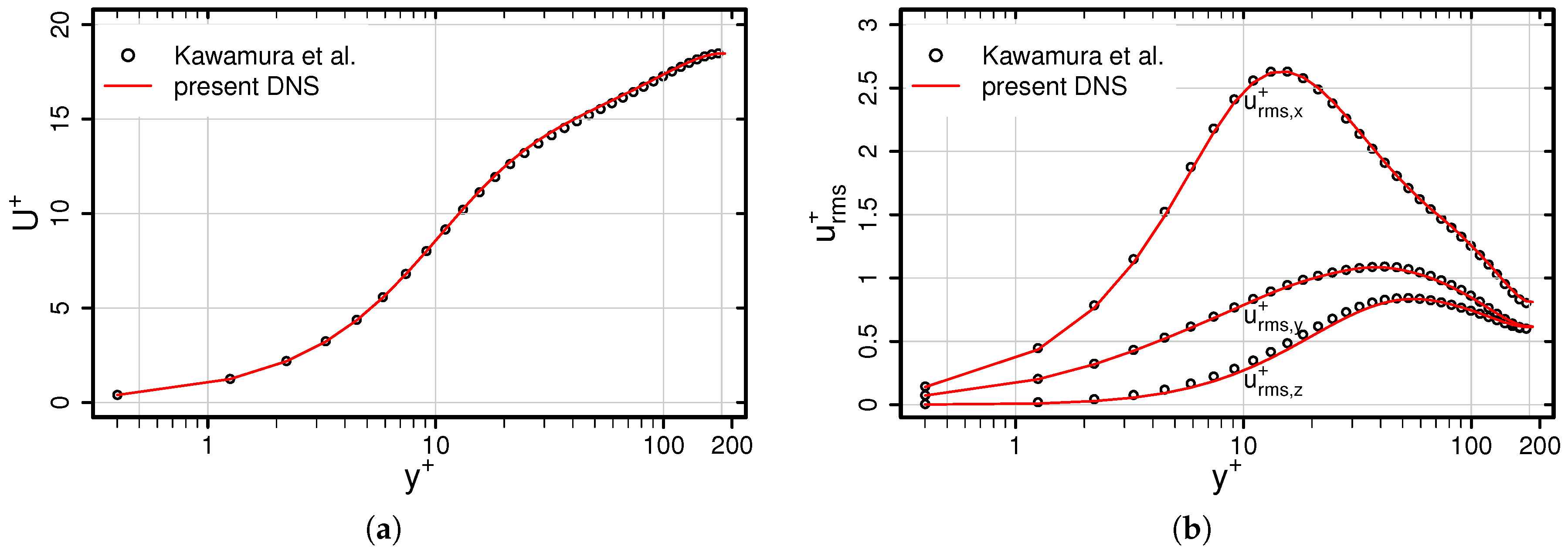
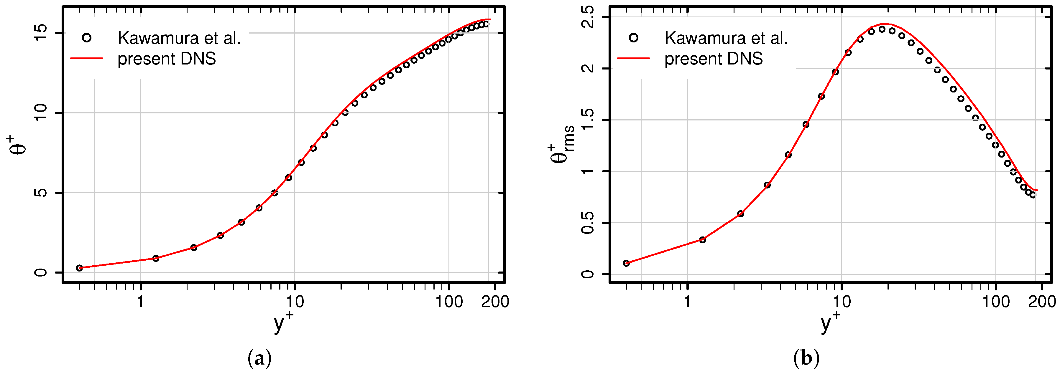
Figure A2 shows a comparison of the predicted mean and RMS velocities with the reference data of [75]. Results are presented as a function of the non-dimensional wall distance y + .
As is apparent in Figure A2, predicted mean and RMS velocities show excellent agreement with the reference DNS dataset. A similar conclusion can be drawn for the mean and RMS temperature profiles depicted in Figure A3. This confirms that the numerical methods applied are appropriate to describe the thermofluid processes inside the heated channel flow and can then be used for further investigation studies.
Figure A2. Mean (a) and RMS (b) velocities as a function of the non-dimensional wall distance y + . Comparison of results from the present DNS with the reference data of [75].
Energies 11 01354 g0a2
Figure A3. Mean (a) and RMS (b) temperature as a function of the non-dimensional wall distance y + . Comparison of results from the present DNS with the reference data of [75].
Energies 11 01354 g0a3

References

  1. Sunden, B.; Xie, G. Gas Turbine Blade Tip Heat Transfer and Cooling: A Literature Survey. Heat Transf. Eng. 2010, 31, 527–544. [Google Scholar] [CrossRef]
  2. Zuckerman, N.; Lior, N. Impingement Heat Transfer: Correlations, and Numerical Modeling. J. Heat Transf. 2005, 127, 544–552. [Google Scholar] [CrossRef]
  3. Zuckerman, N.; Lior, N. Jet Impingement Heat Transfer: Physics, Correlations, and Numerical Modeling. Adv. Heat Transf. 2006, 39, 565–631. [Google Scholar] [CrossRef]
  4. Martin, H. Heat and mass transfer between impinging gas jets and solid surfaces. Adv. Heat Transf. 1997, 13, 1–60. [Google Scholar] [CrossRef]
  5. Jambunathan, K.; Lai, E.; Moss, M.A.; Button, B.L. A review of heat transfer data for single circular jet impingement. Int. J. Heat Fluid Flow 1992, 13, 106–115. [Google Scholar] [CrossRef]
  6. Viskanta, R. Heat transfer to impinging isothermal gas and flame jets. Exp. Therm. Fluid Sci. 1993, 6, 106–115. [Google Scholar] [CrossRef]
  7. Molana, M.; Banooni, S. Investigation of heat transfer processes involved liquid impingement jets: A review. Braz. J. Chem. Eng. 2013, 30, 413–435. [Google Scholar] [CrossRef]
  8. Weigand, B.; Spring, S. Multiple Jet Impingement—A Review. Heat Transf. Res. 2011, 42, 101–142. [Google Scholar] [CrossRef]
  9. Dewan, A.; Dutta, R.; Srinivasan, B. Recent Trends in Computation of Turbulent Jet Impingement Heat Transfer. Heat Transf. Eng. 2012, 33, 447–460. [Google Scholar] [CrossRef]
  10. Baughn, J.W.; Shimizu, S. Heat Transfer Measurements From a Surface With Uniform Heat Flux and an Impinging Jet. J. Heat Transf. 1989, 111, 1096–1098. [Google Scholar] [CrossRef]
  11. Kim, K.-S. An experimental study on the flow and heat transfer characteristics of an impinging jet. KSME J. 1993, 7, 258–271. [Google Scholar] [CrossRef]
  12. Hrycak, P. Heat transfer from round impinging jets to a flat plate. Int. J. Heat Mass Transf. 1993, 7, 1857–1865. [Google Scholar] [CrossRef]
  13. Katti, V.; Prahub, S.V. Experimental study and theoretical analysis of local heat transfer distribution between smooth flat surface and impinging air jet from a circular straight pipe nozzle. Int. J. Heat Mass Transf. 2008, 51, 4480–4495. [Google Scholar] [CrossRef]
  14. Geers, L.F.G.; Hanjalić, K.; Tummers, M.J. Wall imprint of turbulent structures and heat transfer in multiple impinging jet arrays. J. Fluid Mech. 2006, 546, 255–284. [Google Scholar] [CrossRef]
  15. Roux, S.; Fénot, M.; Lalizel, G.; Brizzi, L.-E.; Dorignac, E. Evidence of flow vortex signatures on wall fluctuating temperature using unsteady infrared thermography for an acoustically forced impinging jet. Int. J. Heat Mass Transf. 2014, 50, 38–50. [Google Scholar] [CrossRef]
  16. Gulati, P.; Katti, V.; Prabhu, S.V. Influence of the shape of the nozzle on local heat transfer distribution between smooth flat surface and impinging air jet. Int. J. Therm. Sci. 2008, 48, 602–617. [Google Scholar] [CrossRef]
  17. Lee, J.; Lee, S.-J. The effect of nozzle configuration on stagnation region heat transfer enhancement of axisymmetric jet impingement. Int. J. Heat Mass Transf. 2000, 43, 3497–3509. [Google Scholar] [CrossRef]
  18. Brignoni, L.A.; Garimella, S.V. Effects of nozzle-inlet chamfering on pressure drop and heat transfer in confined air jet impingement. Int. J. Heat Mass Transf. 2000, 43, 1133–1139. [Google Scholar] [CrossRef]
  19. Vinze, R.; Chandel, S.M.; Lomaye, M.D.; Prabhu, S.V. Influence of jet temperature and nozzle shape on the heat transfer distribution between a smooth plate and impinging air jets. Int. J. Therm. Sci. 2016, 99, 136–151. [Google Scholar] [CrossRef]
  20. Trinh, X.T.; Fénot, M.; Dorignac, E. The effect of nozzle geometry on local convective heat transfer to unconfined impinging air jets. Exp. Therm. Fluid Sci. 2016, 70, 1–16. [Google Scholar] [CrossRef]
  21. Meena, H.C.; Reodikar, S.A.; Vinze, R.; Prabhu, S.V. Influence of the shape of the orifice on the local heat transfer distribution between smooth flat surface and impinging incompressible air jet. Exp. Therm. Fluid Sci. 2016, 70, 292–306. [Google Scholar] [CrossRef]
  22. Yan, X.; Saniei, N. Heat transfer from an obliquely impinging circular air jet to a flat plate. Int. J. Heat Fluid Flow 1997, 18, 591–599. [Google Scholar] [CrossRef]
  23. O’Donovan, T.S.; Murray, D.B. Fluctuating fluid flow and heat transfer of an obliquely impinging air jet. Int. J. Heat Mass Transf. 2008, 51, 6169–6179. [Google Scholar] [CrossRef]
  24. Choo, K.; Kang, T.Y.; Kim, S.J. The effect of inclination on impinging jets at small nozzle-to-plate spacing. Int. J. Heat Mass Transf. 2012, 18, 3327–3334. [Google Scholar] [CrossRef]
  25. Akansu, Y.E.; Sarioglu, M.; Kuvvet, K.; Yavuz, T. Flow field and heat transfer characteristics in an oblique slot jet impinging on a flat plate. Int. Commun. Heat Mass Transf. 2008, 35, 873–880. [Google Scholar] [CrossRef]
  26. Goldstein, R.J.; Franchett, M.E. Heat Transfer From a Flat Surface to an Oblique Impinging Jet. J. Heat Transf. 1988, 110, 84–90. [Google Scholar] [CrossRef]
  27. Bouchez, J.-P.; Goldstein, R.J. Impingement cooling from a circular jet in a cross flow. Int. J. Heat Mass Transf. 1975, 18, 719–730. [Google Scholar] [CrossRef]
  28. Roux, S.; Fénot, M.; Lalizel, G.; Brizzi, L.-E.; Dorignac, E. Experimental investigation of the flow and heat transfer of an impinging jet under acoustic excitation. Int. J. Heat Mass Transf. 2011, 54, 3277–3290. [Google Scholar] [CrossRef]
  29. Ghadi, S.; Esmailpour, K.; Hosseinalipour, S.M.; Mujumdar, A. Experimental study of formation and development of coherent vortical structures in pulsed turbulent impinging jet. Exp. Therm. Fluid Sci. 2016, 74, 382–389. [Google Scholar] [CrossRef]
  30. Manceau, R.; Perrin, R.; Hadžiabdić, M.; Benhamadouche, S. Investigation of the interaction of a turbulent impinging jet and a heated, rotating disk. Phys. Fluids 2014, 26, 035102. [Google Scholar] [CrossRef]
  31. Gabour, L.A.; Lienhard, J.H. Wall Roughness Effects on Stagnation-Point Heat Transfer Beneath an Impinging Liquid Jet. J. Heat Transf. 1994, 116, 81–87. [Google Scholar] [CrossRef]
  32. Ying, Z.; Guiping, L.; Xueqin, B.; Lizhan, B.; Dongsheng, W. Experimental study of curvature effects on jet impingement heat transfer on concave surfaces. Chin. J. Aeronaut. 2017, 30, 586–594. [Google Scholar] [CrossRef]
  33. Voke, P.R.; Gao, S. Numerical study of heat transfer from an impinging jet. Int. J. Heat Mass Transf. 1998, 41, 671–680. [Google Scholar] [CrossRef]
  34. Cziesla, T.; Biswas, G.; Chattopadhyay, H.; Mitra, N.K. Large-eddy simulation of flow and heat transfer in an impinging slot jet. Int. J. Heat Fluid Flow 2001, 22, 500–508. [Google Scholar] [CrossRef]
  35. Beaubert, F.; Viazzo, S. Large eddy simulations of plane turbulent impinging jets at moderate Reynolds numbers. Int. J. Heat Fluid Flow 2003, 24, 512–519. [Google Scholar] [CrossRef]
  36. Hadžiabdić, M.; Hanjalić, K. Vortical structures and heat transfer in a round impinging jet. J. Fluid Mech. 2008, 596, 221–260. [Google Scholar] [CrossRef]
  37. Uddin, N.; Neumann, A.O.; Weigand, B. LES simulations of an impinging jet: On the origin of the second peak in the Nusselt number distribution. Int. J. Heat Mass Transf. 2013, 57, 356–368. [Google Scholar] [CrossRef]
  38. Grenson, P.; Deniau, H. Large-Eddy simulation of an impinging heated jet for a small nozzle-to-plate distance and high Reynolds number. Int. J. Heat Fluid Flow 2017, 68, 348–363. [Google Scholar] [CrossRef]
  39. Aillaud, P.; Duchaine, F.; Gicquel, L.Y.M.; Didorally, S. Secondary peak in the Nusselt number distribution of impinging jet flows: A phenomenological analysis. Phys. Fluids 2016, 28, 095110. [Google Scholar] [CrossRef]
  40. Natarajan, T.; Jewkes, J.W.; Lucey, A.D.; Narayanaswamy, R.; Chung, Y.M. Large-eddy simulations of a turbulent jet impinging on a vibrating heated wall. Int. J. Heat Fluid Flow 2017, 65, 277–298. [Google Scholar] [CrossRef]
  41. Satake, S.; Kunugi, T. Direct numerical simulation of an impinging jet into parallel disks. Int. J. Numer. Method Heat Fluid Flow 1998, 8, 768–780. [Google Scholar] [CrossRef]
  42. Chung, Y.M.; Luo, K.H. Unsteady Heat Transfer Analysis of an Impinging Jet. J. Heat Transf. 2002, 124, 1039–1048. [Google Scholar] [CrossRef]
  43. Hattori, H.; Nagano, Y. Direct numerical simulation of turbulent heat transfer in plane impinging jet. Int. J. Heat Fluid Flow 2004, 25, 749–758. [Google Scholar] [CrossRef]
  44. Tsujimoto, K.; Ishikura, T.; Shakouchi, T.; Ando, T. Direct Numerical Simulation of Active-Controlled Impinging Jets. J. Fluid Sci. Technol. 2009, 4, 279–291. [Google Scholar] [CrossRef]
  45. Jaramillo, J.E.; Trias, F.X.; Gorobets, A.; Pérez-Segarra, C.D.; Oliva, A. DNS and RANS modelling of a turbulent plane impinging jet. Int. J. Heat Mass Transf. 2012, 55, 789–801. [Google Scholar] [CrossRef]
  46. Dairay, T.; Fortuné, V.; Lamballais, E.; Brizzi, L.-E. Direct numerical simulation of a turbulent jet impinging on a heated wall. J. Fluid Mech. 2015, 764, 362–394. [Google Scholar] [CrossRef]
  47. Wilke, R.; Sesterhenn, J. Statistics of fully turbulent impinging jets. J. Fluid Mech. 2017, 825, 795–824. [Google Scholar] [CrossRef]
  48. Olsson, M.; Fuchs, L. Large eddy simulations of a forced semiconfined circular impinging jet. Phys. Fluids 1998, 10, 476. [Google Scholar] [CrossRef]
  49. Lodato, G.; Vervisch, L.; Domingo, P. A compressible wall-adapting similarity mixed model for large-eddy simulation of the impinging round jet. Phys. Fluids 2009, 21, 035102. [Google Scholar] [CrossRef]
  50. Koide, T.; Tsujimoto, K.; Shakouchi, T.; Ando, T. DNS analysis of multiple impinging jets. J. Fluid Sci. Technol. 2014, 9, JFST0027. [Google Scholar] [CrossRef]
  51. Draksler, M.; Končar, B.; Cizelj, B.; Ničeno, B. Large Eddy Simulation of multiple impinging jets in hexagonal configuration—Flow dynamics and heat transfer characteristics. Int. J. Heat Mass Transf. 2017, 109, 16–27. [Google Scholar] [CrossRef]
  52. Jefferson-Loveday, R.J.; Tucker, P.G. LES of Impingement Heat Transfer on a Concave Surface. Numer. Heat Transf. Part A Appl. 2010, 58, 247–271. [Google Scholar] [CrossRef]
  53. Aillaud, P.; Gicquel, L.Y.M.; Duchaine, F. Investigation of the concave curvature effect for an impinging jet flow. Phys. Rev. Fluids 2017, 2, 114608. [Google Scholar] [CrossRef]
  54. Popovac, M.; Hanjalić, K. Large-eddy simulations of flow over a jet-impinged wall-mounted cube in cross stream. Int. J. Heat Fluid Flow 2007, 28, 1360–1378. [Google Scholar] [CrossRef]
  55. Rundström, D.; Moshfegh, B. Large-eddy simulation of an impinging jet in cross-flow on a heated wall-mounted cube. Int. J. Heat Mass Transf. 2009, 52, 921–931. [Google Scholar] [CrossRef]
  56. Kiełczewski, K.; Tuliszka-Sznitko, E. Numerical study of the flow structure and heat transfer in rotating cavity with and without jet. Arch. Mech. 2013, 65, 527–548. [Google Scholar]
  57. Gojon, R.; Bogey, C.; Marsden, O. Large-eddy simulation of supersonic planar jets impinging on a flat plate at an angle of 60 to 90 degrees. In Proceedings of the 21st AIAA/CEAS Aeroacoustics Conference, Dallas, TX, USA, 22–26 June 2015. [Google Scholar] [CrossRef]
  58. Bovo, M.; Rojo, B. Single Pulse Jet Impingement on Inclined Surface, Heat Transfer and Flow Flied. In Proceedings of the 11th International Conference on Engines & Vehicles, Napoli, Italy, 15–19 September 2013. [Google Scholar] [CrossRef]
  59. Ries, F.; Li, Y.; Rißmann, M.; Klingenberg, D.; Nishad, K.; Böhm, B.; Dreizler, A.; Janicka, J.; Sadiki, A. Database of near-wall turbulent flow properties of a jet impinging on a solid surface under different inclination angles. Fluids 2018, 3, 5. [Google Scholar] [CrossRef]
  60. Sadiki, A.; Hutter, K. On thermodynamics of turbulence: Development of first order closure models and critical evaluation of existing models. J. Non-Equilib. Thermodyn. 2000, 25, 131–160. [Google Scholar] [CrossRef]
  61. Ries, F.; Janicka, J.; Sadiki, A. Thermal Transport and Entropy Production Mechanisms in a Turbulent Round Jet at Supercritical Thermodynamic Conditions. Entropy 2017, 19, 404. [Google Scholar] [CrossRef]
  62. Bejan, A. Second-law analysis in heat transfer and thermal design. Adv. Heat Transf. 1982, 15, 1–58. [Google Scholar] [CrossRef]
  63. Bejan, A. Entropy Generation Minimization: The Method of Thermodynamic Optimization of Finite-size Systems and Finite-Time Processes; CRC Press LLC: Boca Raton, FL, USA, 1995; ISBN 978-0849396519. [Google Scholar]
  64. Ahmadi, G.A. A two-equation turbulence model for compressible flows based on the second law of thermodynamics. J. Non-Equilib. Thermodyn. 1989, 14, 49–59. [Google Scholar] [CrossRef]
  65. Sadiki, A. Extended thermodynamics as modeling tool of turbulence in fluid flows. In Trends in Applications of Mathematics to Mechanics; Wang, Y., Hutter, K., Eds.; Shaker Verlag: Aachen, Germany, 2005; ISBN 978-3-8322-3600-7. [Google Scholar]
  66. Behnia, M.; Parneix, S.; Shabany, Y.; Durbin, P.A. Numerical study of turbulent heat transfer in confined and unconfined impinging jets. Int. J. Heat Fluid Flow 1999, 20, 1–9. [Google Scholar] [CrossRef]
  67. Dutta, R.; Dewan, A.; Srinivasan, B. Comparison of various integration to wall (ITW) RANS models for predicting turbulent slot jet impingement heat transfer. Int. J. Heat Mass Transf. 2013, 65, 750–764. [Google Scholar] [CrossRef]
  68. Shuja, S.Z.; Yilbas, B.S.; Budair, M.O. Local entropy generation in an impinging jet: Minimum entropy concept evaluating various turbulence models. Comput. Method Appl. Mech. Eng. 2001, 190, 3623–3644. [Google Scholar] [CrossRef]
  69. Xu, P.; Sasmito, A.P.; Qiu, S.; Mujumdar, A.S.; Xu, L.; Geng, L. Heat transfer and entropy generation in air jet impingement on a model rough surface. Int. Commun. Heat Mass Transf. 2016, 72, 48–56. [Google Scholar] [CrossRef]
  70. Esmailpour, K.; Bozorgmehr, B.; Hosseinalipour, S.M.; Mujumdar, A.S. Entropy generation and second law analysis of pulsed impinging jet. Int. J. Numer. Method Heat Fluid Flow 2015, 25, 1089–1106. [Google Scholar] [CrossRef]
  71. Chorin, A.J. Numerical Solution of the Navier-Stokes Equations. Math. Comput. 1968, 22, 745–762. [Google Scholar] [CrossRef]
  72. Van der Houwen, P.J. Explicit Runge-Kutta formulas with increased stability boundaries. Numer. Math. 1972, 20, 149–164. [Google Scholar] [CrossRef]
  73. Roe, P.L. Characteristic-Based Schemes for the Euler Equations. Annu. Rev. Fluid Mech. 1987, 18, 337–365. [Google Scholar] [CrossRef]
  74. Pope, S.B. Turbulent Flows, 11th ed.; Cambridge University Press: Cambridge, UK, 2011; ISBN 9780521598866. [Google Scholar]
  75. Kawamura, H.; Abe, H.; Matsuo, Y. DNS of turbulent heat transfer in channel flow with respect to Reynolds and Prandtl number effects. Int. J. Heat Fluid Flow 1999, 20, 196–207. [Google Scholar] [CrossRef]
  76. Panchapakesan, N.R.; Lumley, J.L. Turbulence measurements in axisymmteric jets of air and helium. Part 2. Helium jet. J. Fluid Mech. 1993, 246, 225–247. [Google Scholar] [CrossRef]
  77. Schumann, U. The counter gradient heat flux in turbulent stratified flows. Nucl. Eng. Des. 1986, 100, 255–262. [Google Scholar] [CrossRef] [Green Version]
  78. Batchelor, G.K. Diffusion in a field of homogeneous turbulence: II. The relative motion of particles. Math. Proc. Camb. 1952, 48, 345–362. [Google Scholar] [CrossRef]
  79. Daly, B.J.; Harlow, F.H. Transport equations in turbulence. Phys. Fluids 1970, 13, 2637–2649. [Google Scholar] [CrossRef]
  80. Peng, S.H.; Davidson, L. On a subgrid-scale heat flux model for large eddy simulation of turbulent thermal flow. Int. J. Heat Mass Transf. 2002, 45, 1393–1405. [Google Scholar] [CrossRef]
  81. Younis, B.A.; Spezial, C.G.; Clark, T.T. A rational model for the turbulent scalar flux. Proc. R. Soc. A 2004, 461, 575–594. [Google Scholar] [CrossRef]
  82. Pantangi, P.; Huai, Y.; Sadiki, A. Mixing analysis and optimization in jet mixer systems by means of large eddy simulation. In Micro Macro Mixing; Springer: Berlin/Heidelberg, Germany, 2010; pp. 205–226. [Google Scholar] [CrossRef]
  83. Béguier, C.; Dekeyser, I.; Launder, B.E. Ratio of scalar and velocity dissipation time scales in shear flow turbulence. Phys. Fluids 1978, 21, 307–310. [Google Scholar] [CrossRef]
  84. Jou, D.; Casas-Vázquez, J.; Lebon, G. Extended Irreversible Thermodynamics; Springer: New York, NY, USA, 1996; Volume 2, ISBN 3-540-60789-7. [Google Scholar]
  85. Hua, Y.-C.; Zhao, T.; Guo, T. Irreversibility and Action of the Heat Conduction Process. Entropy 2018, 20, 206. [Google Scholar] [CrossRef]
  86. Guo, Z.-Y.; Zhu, H.-Y.; Liang, X.-G. Entransy-A physical quantity describing heat transfer ability. Int. J. Heat Mass Transf. 2007, 50, 2545–25556. [Google Scholar] [CrossRef]
  87. Kock, F.; Herwig, H. Local entropy production in turbulent shear flows: A high-Reynolds number model with wall functions. Int. J. Heat Mass Transf. 2004, 47, 2205–2215. [Google Scholar] [CrossRef]
  88. Komen, E.; Shams, A.; Camilo, L.; Koren, B. Quasi-DNS capabilities of OpenFOAM for different mesh types. Comput. Fluids 2017, 96, 87–104. [Google Scholar] [CrossRef]
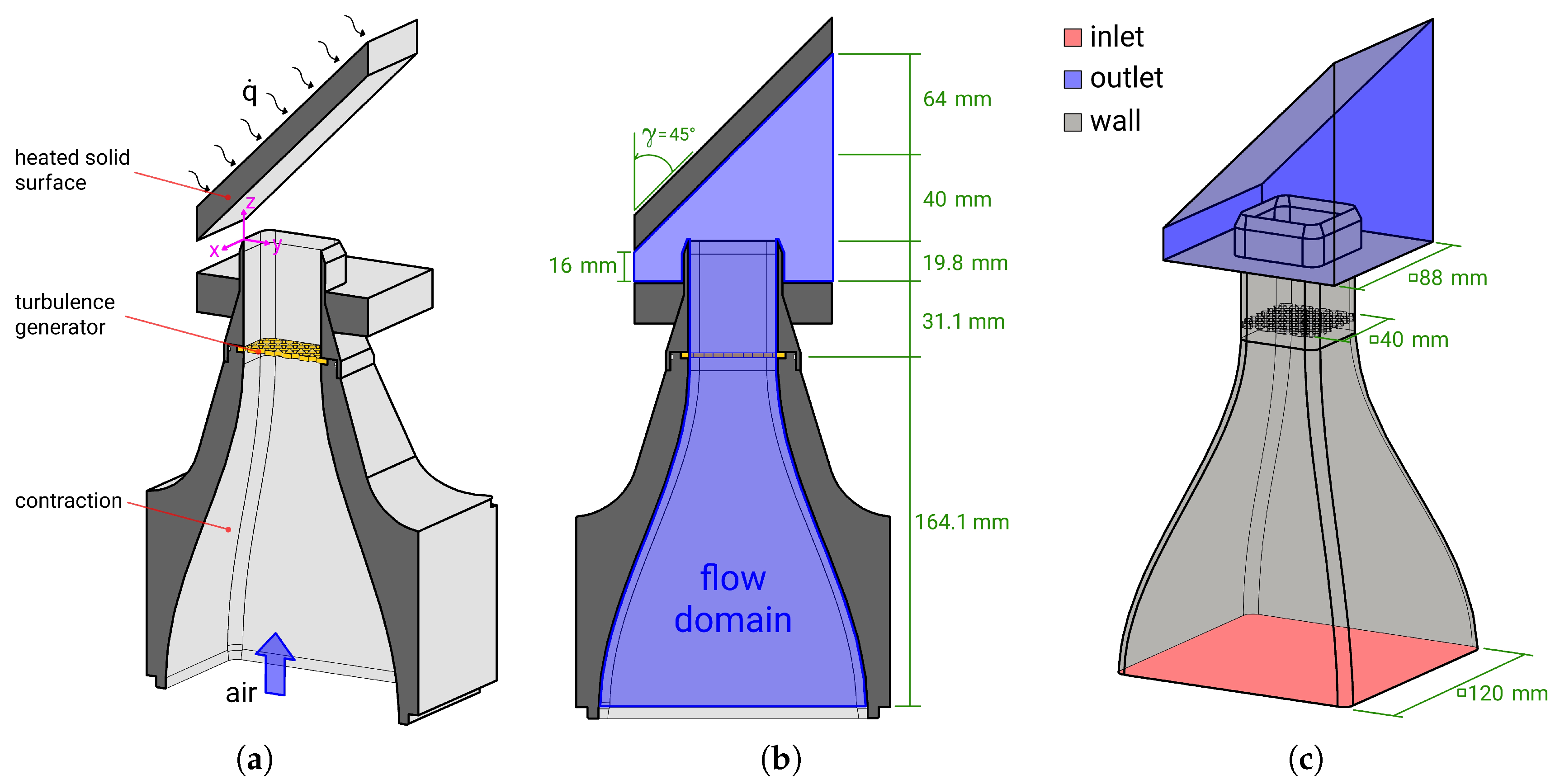
Figure 1. Schematic of the inclined impinging jet configuration. (a) trimetric view; (b) cutting view at the mid-plane section; (c) computational domain and boundaries.
Energies 11 01354 g001
Figure 2. Instances of: (a) instantaneous magnitude velocity at the mid-plane section; (b) time-averaged magnitude velocity at the mid-plane section with superimposed streamlines of mean velocity; and (c) time-averaged absolute shear stress induced by the inclined jet on the impinged wall.
Energies 11 01354 g002
Figure 3. Coordinate system and sampling locations at ζ / D = 0.5 , 0.15 , 0 , 0.5 , 1 .
Energies 11 01354 g003
Figure 4. (a) The mean Θ ¯ () and RMS temperature Θ R M S () with respect to the non-dimensional wall distance; (b) thermal boundary layer thickness δ Θ () and peak values of turbulent kinetic energy k () and RMS temperature Θ R M S () along the wall parallel direction ζ / D .
Energies 11 01354 g004
Figure 5. Normalized budget terms of T 2 ¯ (a) and k (b) along the wall-normal direction at ζ / D = 0 and ζ / D = 0.15 .
Energies 11 01354 g005
Figure 6. Wall-parallel (a) and wall-normal (b) components of the turbulent heat flux vector and mean temperature gradient at different wall-normal traverses. (): mean temperature gradient i Θ ¯ ; (): turbulent heat flux vector U i Θ ¯ .
Energies 11 01354 g006
Figure 7. (a) Anisotropy map of heat fluxes. Δ: ζ / D = 0.5 , □: ζ / D = 0.15 , ○: ζ / D = 0 , +: ζ / D = 1 . The dashed line represents the isotropic state where U ζ Θ ¯ η Θ ¯ = U η Θ ¯ ζ Θ ¯ . (b) The ratio of mechanical ( τ = k / ϵ ) and thermal ( τ θ = T 2 ¯ / ϵ T 2 ¯ ) time scales along the wall-parallel direction at a wall distance of η = 0.5 δ Θ .
Energies 11 01354 g007
Figure 8. (a) Instantaneous and (b) time-averaged instances of the Nusselt number at the impinging wall.
Energies 11 01354 g008
Figure 9. Profiles of the time-averaged Nusselt number () and magnitude wall-shear stress () in: (a) the span-wise direction x; and (b) the wall-parallel direction ζ .
Energies 11 01354 g009
Figure 10. Snapshots of entropy generation rate by (a) viscous dissipation and (b) heat transport at the mid-plane section of the inclined impinging jet.
Energies 11 01354 g010
Figure 11. (a) Profiles of time-averaged entropy production rates due to viscous dissipation Π ¯ v and to heat conduction Π ¯ q as a function of non-dimensional wall distance η / D ; (b) boundary layer thickness of Π ¯ v and Π ¯ q .
Energies 11 01354 g011
Figure 12. Profiles of mean, turbulent and total entropy production rates due to (a) viscous dissipation and (b) heat conduction at ζ / D = 0.15 . Dashed lines represent turbulent parts of entropy production rates estimated by means of turbulent dissipation rates.
Energies 11 01354 g012
Table 1. Thermal and fluid flow features of the inclined impinging jet configuration.
PropertyDescriptionValue
γ inclination angle of the plate 45
Dnozzle exit diameter40 mm
Hjet-to-plate distance40 mm
U i n l e t velocity at the contraction entrance 0.214 m/s
T i n l e t temperature at the contraction entrance290 K
T w a l l wall temperature of the heated surface330 K
pambient pressure 1.01325 bar
R e D Reynolds-number based on nozzle exit diameter5000
P r molecular Prandtl number 0.71