1. Introduction
FOWTs provide the possibility to reach offshore deep water areas, where wind quality is better: higher wind speed, less turbulence and less severe shear. This also solves the lack of available emplacements for new onshore wind farms and reduces the visual and noise impact of large scale wind turbines [
1]. These FOWT systems present different platform hydrodynamic restoring stiffness depending on the floating technology: spar-buoy (spar), tension leg platforms (TLP) and barge-like or semi-submersible platforms (barge) [
2]. All these floating platform technologies can be stabilised by purely mechanical means, i.e., ballast [
3], taut cables [
4] and hydrodynamic design [
5], respectively. However, such means present considerable disadvantages in terms of cost, which is driven by size and complexity [
6].
Barge platforms present some building, deployment, anchoring, site independence and decommissioning advantages over the others, but they are limited in terms of platform-pitch stability, wave sensitivity and control complexity [
7,
8]. This poses great challenges for control engineering to develop control algorithms able to improve the system performance, and hence the turbine life-time. These challenges are influenced by barge dimensions and shape, which also affects the Levelized Cost Of Energy (LCOE) due to the platform Capital Investment Cost (CAPEX) [
9].
Several attempts have been done to control and improve FOWT systems—however, not so many for barge mounted systems. This is because of the dilemma presented by this type of platform. When the blade-pitch action tries to regulate the generator speed in the above rated wind speed, a coupling between blade-pitch and platform-pitch motions can happen [
10], known as the negative platform damping effect. This phenomenon makes the turbine unstable, potentially damaging mechanical components. One of the first and most complete studies done to tackle this phenomenon was carried out in [
11], where three control alternatives were proposed to mitigate the barge platform-pitch motions. The best results were achieved detuning the blade-pitch PI control gains. Great reductions in the platform-pitch motion and in the mechanical component loads were achieved. However, the generator speed regulation quickness was degraded.
Several Linear Quadratic Regulator (LQR) based controller designs are compared with the baseline blade-pitch PI controller in [
12]. The LQR Gain-Scheduling (GS) and the Linear Parameter-Varying (LPV) GS State-Feedback (SF) control techniques show the best results. The LQR GS control provides the best power regulation, whereas the LPV GS SF provides the best platform-pitch damping. The baseline blade-pitch PI controller used for the comparison is tuned with those blade-pitch PI gains used for onshore wind turbines. Unfortunately, a mechanical load analysis is missing to verify the impact of the proposed controllers on the mechanical components.
A comparison between the Individual Pitch Control (IPC) and the Collective Pitch Control (CPC) is presented in [
13]. The IPC is based on three modules: the Disturbance Accommodating Control (DAC) aimed at eliminating the wind disturbances, the Model Predictive Control (MPC) to remove the influence of wave disturbances, and the fuzzy control module to combine both these algorithms. Both IPC and CPC techniques improve the power production quality while reducing the tower and blade bending moments compared with those obtained from using the baseline blade-pitch PI control tuned with the same previously cited onshore values. Moreover, the IPC technique provides a better reduction in the tower and blade bending moments than the CPC one. However, the generator speed regulation is not depicted.
The CPC and two IPCs strategies are compared, one conventional and the other with a memory based blade-pitch compensation technique in [
14]. Good improvements are shown with the conventional IPC in blade and tower bending moments, and even better with the memory based blade-pitch compensation IPC. Great power and generator speed error reductions are shown. However, some time-domain results are not shown as the generator speed or the blade-pitch activity, for example.
The IPC state space control strategy proposed in [
15] achieves significant reductions in barge platform-pitch, -roll and -yaw motions, and in tower loads. However, the cost of this reduction is the extensive use of the blade-pitch actuator, where the blade-pitch rate is increased by 318% compared to the conventional CPC baseline controller.
The aim of this article is to present an advanced control technique able to mitigate the platform-pitch motion on NREL’s 5MW + ITI Energy barge reference model [
11], while regulating the generator speed, not being detrimental to blade-pitch activity and reducing the tower-base or blade-root bending moments. This control technique is based on an additional control loop, which enables the blade-pitch to more vigorously respond to wind gusts. The influence of this advanced control on an FOWT based on a more compact platform ratio 8 barge is also analysed.
Section 2 provides a review of the platform models used here.
Section 3 describes a control loop, which we call an aerodynamic platform stabiliser (APS), designed to overcome blade-pitch control limitations imposed by the platform-pitch motion dynamics, and applies such a control loop to the reference FOWTs described in
Section 2. The results obtained from the application of such a control strategy are then discussed in
Section 4 and
Section 5, where time-domain simulations and load analysis are presented, respectively.
2. Barge Platform Models
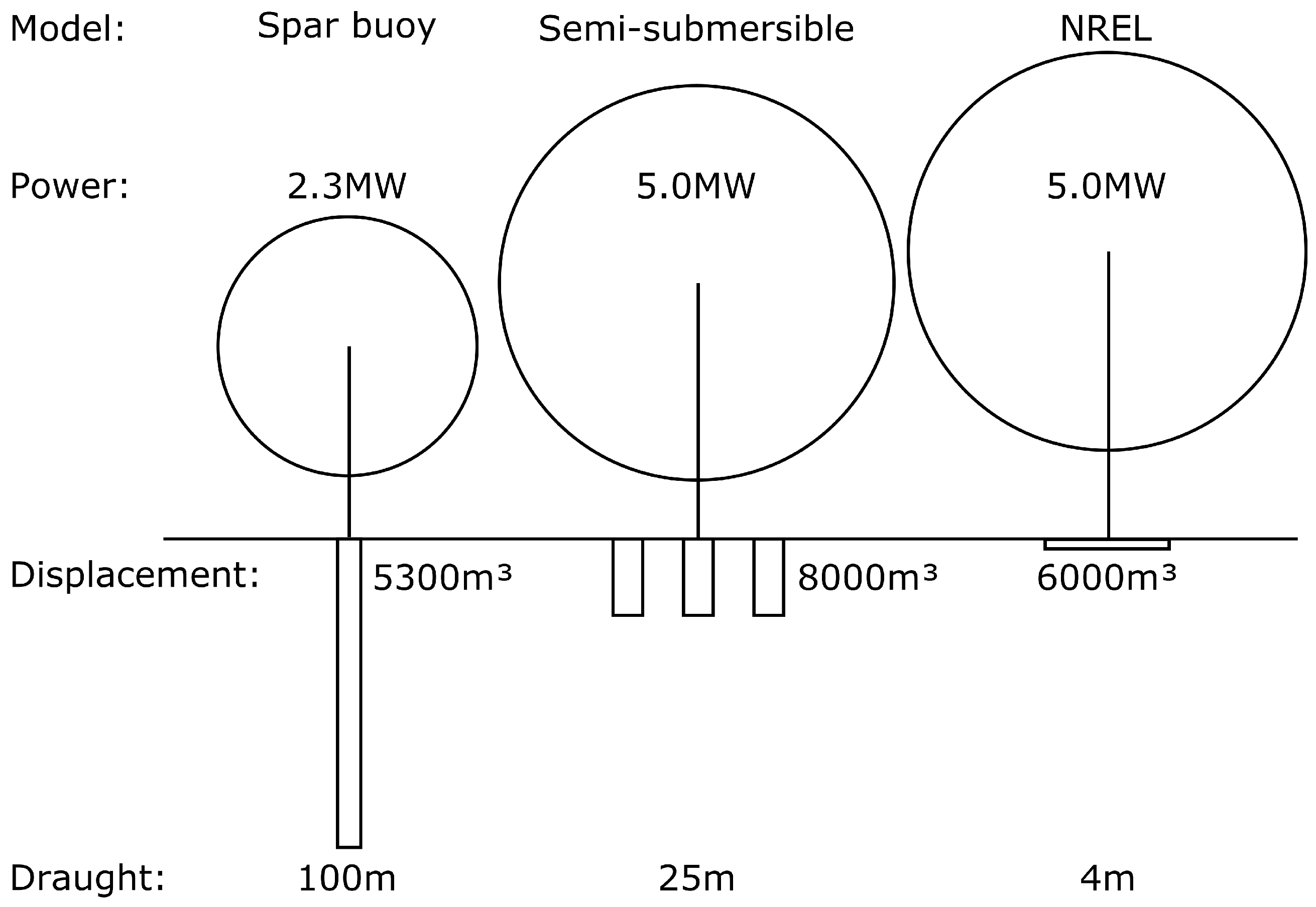
The scaled outlines of three different systems based on two commercial FOWTs and the NREL’s 5MW baseline FOWT mounted on ITI Energy’s barge [
11] are shown in
Figure 1, where the platforms are represented only below the waterline. Note the differences in draught and displacement, which are due to the spar buoy and semi-submersible designs using a ballast for platform stabilisation, while that of the NREL’s design relies mostly on the lateral motion of its centre of buoyancy. Although the barge is manifestly simpler, since it is a more compact platform than those of the two considered commercial FOWTs, its benefits are reaped at the cost of making the turbine controller’s regulation objectives more difficult to achieve, as well as possibly other seaworthiness-related disadvantages. This relationship between platform and controller design, which has been studied in works such as [
11,
16,
17,
18,
19], suggests an incentive for advanced FOWT control techniques to seek tolerance to less stable and more compact platforms. Here, we propose a technique that targets the challenge that such an incentive poses in terms of controller design in the context of some reasonable open FOWT designs.
A variety of considerations, which are outside of this paper’s focus, influence the FOWT platform design. It is, therefore, challenging to systematically study the control needs of FOWTs in general via analysis of specific commercial designs, which may be differently influenced by such considerations. We tried to isolate a single characteristic of FOWT platforms in [
20], concretely its effect on the controller design and performance, by seeking a family of platforms, which are comparable in every other way. We took overall dimensions and inertial properties from ITI Energy’s barge, which are used in the NREL’s FOWT, as a reference for one member of such a family in order to have viability to implementable designs. Moreover, the beam–draught ratio was modified, while other parameters were subjected to a set of restrictions to ensure that the displacement and mass distributions remained somehow plausible, in order to produce other reasonable platform models for our family. Such platform models are different in terms of their influence on the controller design and performance.
In this context, the original ITI Energy barge and a more compact barge platform model, concretely, the beam–draught ratio 8 barge (BD8 barge), are used for the development of this work. The properties of both platforms are summarised in
Table 1. The more compact platform is over 800 tonnes lighter and about 4.3 m narrower, at the expense of one third of its metacentric height. Further reduction of the beam–draught ratio is impractical due to insufficient static stability, even when the turbine is not operating.
The hydrodynamic coefficients for the BD8 barge platform model have been calculated via the Boundary Element Method code NEMOH. These coefficients are displayed in
Figure 2 represented by the dashed lines. The viscous damping and mooring lines are kept as in the NREL’s original model for the sake of simplicity. The original ITI Energy barge hydrodynamic coefficients [
11] are also shown for reference, represented by the continuous lines.
The more compact platform sub-model exhibits lower platform-heave, -pitch and -yaw added mass and damping coefficients, and higher surge added mass and damping coefficients. These facts result in lower hydrodynamic stiffness and damping for the platform-heave, -pitch and -yaw, and higher hydrodynamic damping for platform-surge. This means that a more compact platform will be more pitch motion sensitive to wind gusts. The advanced control technique presented here exploits such a sensitivity for turbine control, thus counterbalancing its negative effect on the traditional blade-pitch PI control.
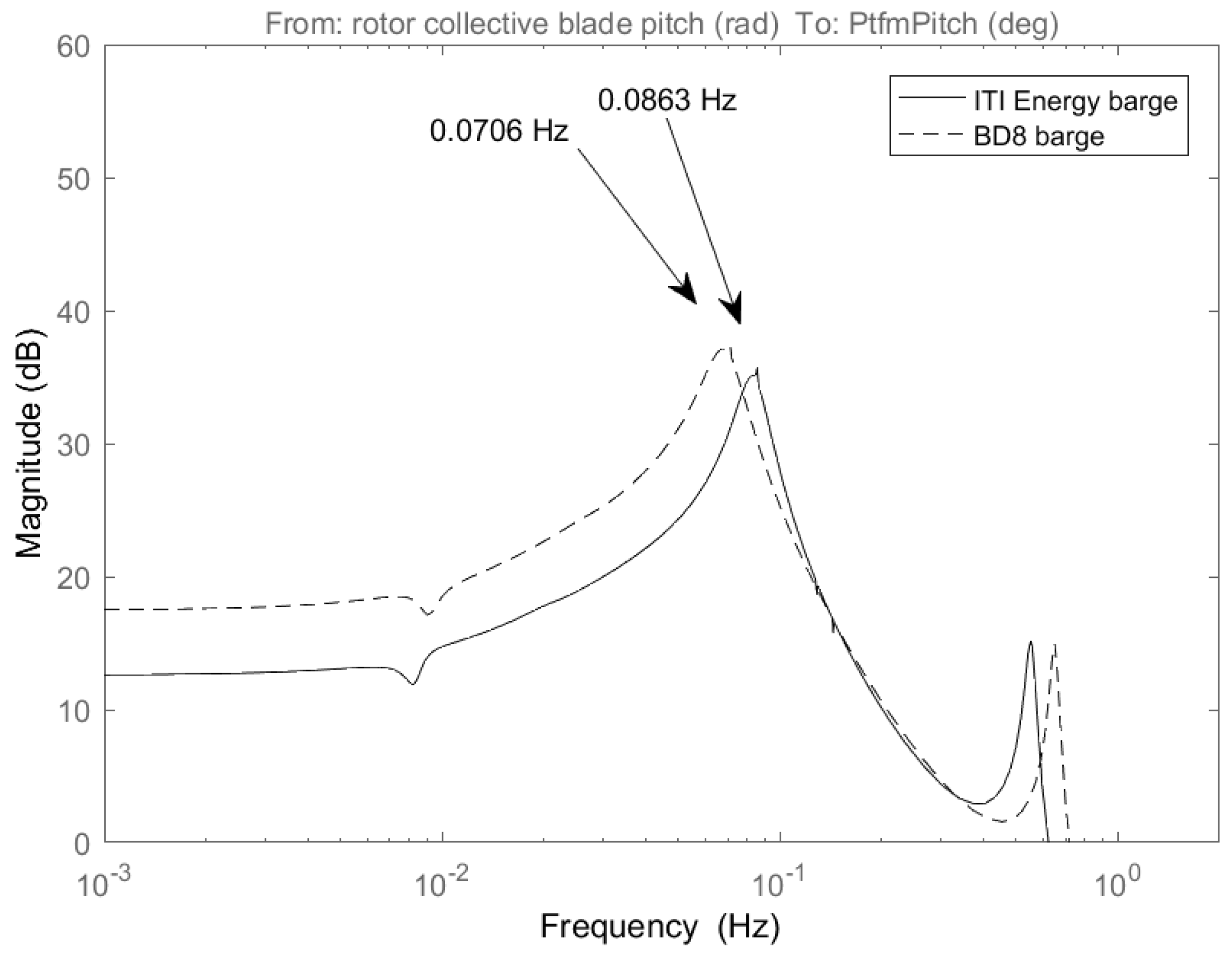
The BD8 barge presents a lower platform-pitch natural frequency than the original ITI Energy barge one. The ITI Energy barge is
= 0.0863 Hz (0.542 rad/s), whereas that of the BD8 barge is
= 0.0706 Hz (0.443 rad/s), as
Figure 3 shows.
3. An Advanced Control Technique
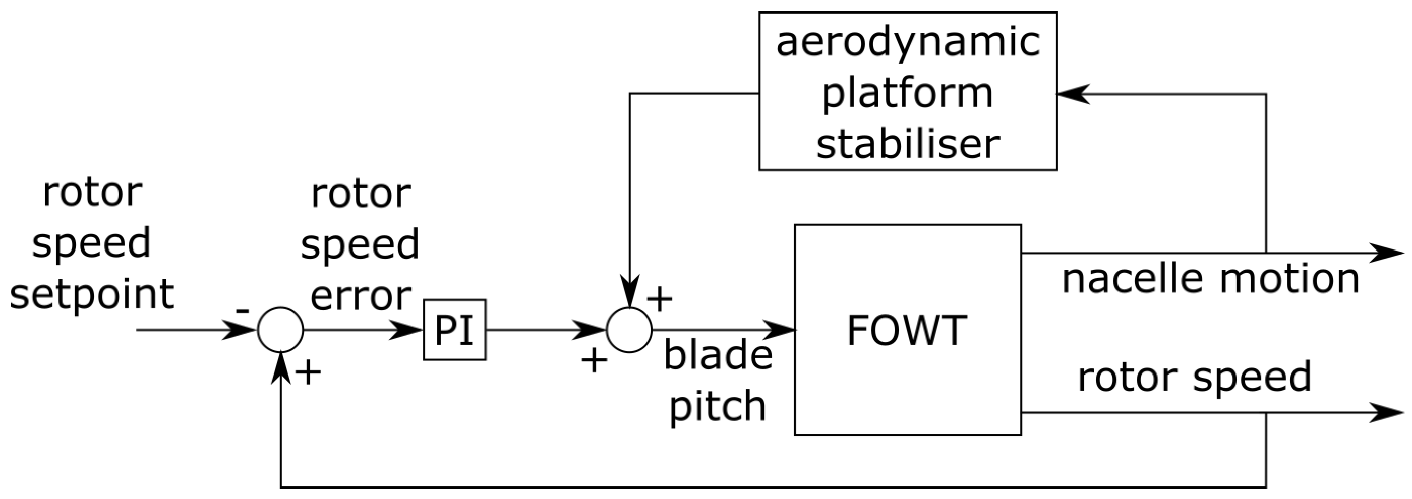
An advanced control technique is designed to work in the above rated wind speed region. This technique is based on the implementation of an additional control loop, called APS, to complement the conventional wind turbine blade-pitch PI control loop, as shown by
Figure 4. The conventional loop is based on the commonly used blade-pitch PI control, which regulates the generator speed via blade-pitch angle variation. The APS loop aerodynamically damps the platform-pitch motion via an additional blade-pitch angle variation. Thus, the final blade-pitch angle is the sum of the angle demands of both control loops. The objective of this control strategy is to reduce platform-pitch oscillations while regulating the generator speed. In addition, it must not be detrimental to the blade-pitch activity or to the loads suffered by mechanical components.
3.1. Aerodynamic Platform Stabiliser
The APS control loop measures the nacelle nod velocity, i.e., the fore-aft velocity, e.g., via an inertial measurement unit, to detect the wind gust events before being detected through the variation of the generator speed. This early thrust detection provides the feasibility of modifying the blade-pitch angle earlier than the conventional blade-pitch PI control loop, due to the large rotor inertia. In this way, the thrust events into the rotor are reduced vigorously and, hence, so are the FOWT platform-pitch oscillations.
The transfer function from the blade-pitch to the nacelle nod velocity has been shaped heuristically. A more traditional platform-pitch damper would seek to produce a blade-pitch ripple in a phase with the nacelle nod velocity at its first natural frequency, exactly as in the case of drivetrain dampers [
21]. This would reduce the self-excitation of the platform-pitch motion. However, the nacelle nod velocity can also be an indicator of the wind speed variation, to which it is desirable to react via blade-pitch variations. This makes the frequencies below the first nacelle nod natural frequency interesting for the generator speed regulation.
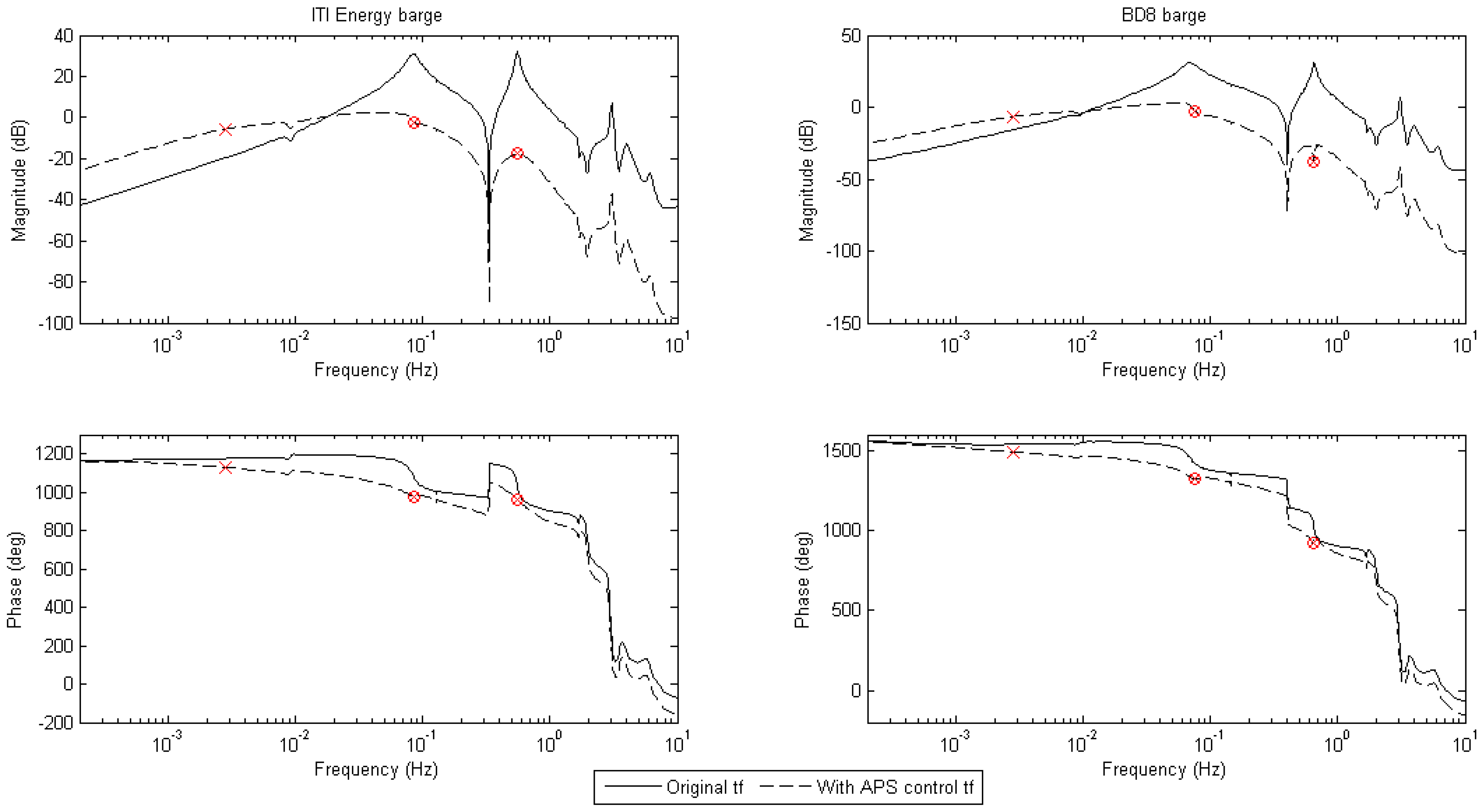
As shown in
Figure 5, our APS consists of a real pole at 0.00278 Hz, which gives the open-loop transfer function the properties we want between the platform-surge and the platform-pitch natural frequencies. Note that the magnitude is flattened and the phase is near a multiple of 360
, which allows us to produce a considerable nacelle-nod-opposing pitch action in a frequency range in which the traditional generator speed regulation cannot act vigorously, so as not to cause negative damping. Two notch filters, at the platform-pitch and blade-flapwise natural frequencies, were also necessary to avoid excessive blade-pitch action at said frequencies.
The transfer function from the nacelle nod velocity to the blade-pitch angle of the designed APS controllers, containing the low-pass pole, the two notch filters and the gain, are described as Equation (
1) for the ITI Energy barge system, and as Equation (
2) for the BD8 barge system:
This control loop does not only dampen the platform-pitch motion, but it also contributes significantly to the generator speed regulation. Traditionally, the conventional control loop results in a compromise between the generator speed regulation, platform-pitch damping, blade-pitch activity and blade/tower bending moments [
22,
23,
24]. However, the proposed APS control loop has the double effect of damping the platform-pitch motion and improving the generator speed regulation. This can be shown in the closed loop bode diagrams from the horizontal hub-height wind speed to the platform-pitch angle (top) and to the generator speed (bottom) displayed in
Figure 6.
Great platform-pitch angle reductions are shown thanks to the implementation of the APS control loop, as one can see in the upper bode diagram of
Figure 6. This gradual mitigation takes place in the range of frequencies from 0.02 Hz to 0.08 Hz in the case of the ITI Energy barge, and from 0.015 Hz to 0.07 Hz in the case of the BD8 barge. One can see a maximum reduction in the platform-pitch natural frequency of 6.5 dB in the ITI Energy barge case, and 7.1 dB in the BD8 barge case. These are the most interesting frequencies to achieve an effective mitigation of the negative platform damping effect. Note that more compact barges have a higher static platform-pitch inclination, as it is indicated by the magnitude difference on the left side of this bode diagram, as well as the previously presented
Table 1 also points out.
The influence of the APS control loop on the generator speed regulation is shown at the bottom of
Figure 6. The magnitude reduction takes place at the same frequency range mentioned above for each barge case, indicating a progressive improvement in the generator speed sensitivity to wind speed variations. The most significant reduction occurs at the resonance frequency of the platform-pitch natural motion, produced by the negative platform damping effect. The reduction for the ITI Energy barge and the BD8 barge systems are 9 dB and 9.2 dB, respectively. Note that the generator speed regulation shows the same response to wind speed variations in both model cases in the aforementioned frequency range, meaning that the generator speed can be regulated equally with a more compact barge FOWT system thanks to the implementation of the APS control technique.
3.2. Conventional Blade-Pitch PI Control Loop
In land-based or offshore bottom-fixed wind turbines, the conventional baseline blade-pitch PI control is usually tuned vigorous enough to respond to wind gusts and regulate generator speed, while maintaining the recommended damping ratio
within the range from 0.6 to 0.7 [
25]. However, in FOWT systems, this controller response has to present a frequency slower than the natural platform-pitch motion one, to avoid the negative platform damping effect [
10]. Thus, one of the first attempts was to reduce the original blade-pitch PI control parameter gains by choosing a smaller controller response natural frequency [
11]. This is known as the blade-pitch detuned PI.
With the BD8 barge FOWT system, the same criteria than that used in the original ITI Energy barge has been maintained for the conventional blade-pitch PI controller loop. Thus, the controller response natural frequency (
) has been reduced according to this more compact platform-pitch natural frequency. In this way, the same controller to platform-pitch frequency relation has been maintained for this compact platform. Furthermore, the damping ratio for this controller has been kept at
= 0.7. The blade-pitch PI gains were obtained from the dynamic equation of the wind turbine drive-train motion, analysed in [
11]. The resulting proportional and integral gain values,
and
, respectively, are given by the following equations:
where the drive-train inertia (
= 534.11 kgm
), the rated rotor speed (
= 12.1 rpm), the gear box ratio (
= 97:1) and the blade-pitch sensitivity at rated wind speed (
= −28.24 ×
watt/rad) have been taken from the NREL 5 MW reference wind turbine [
26]. Both platform system blade-pitch PI gains are summarised in
Table 2.
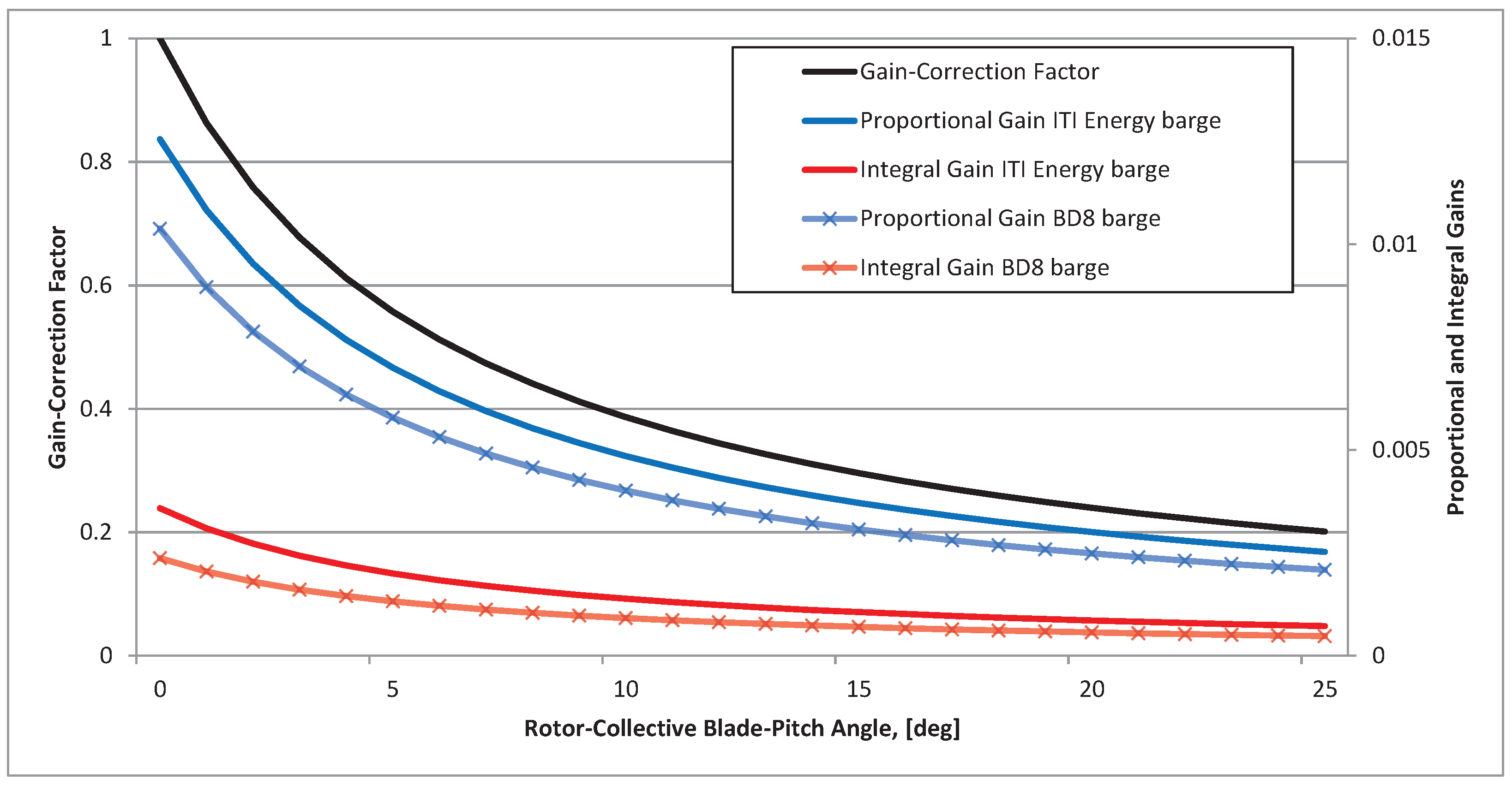
The wind turbine blade-pitch sensitivity increases with wind speed above rated as shown in [
11], so that the blade-pitch PI controller has to be less aggressive at large blade-pitch angles. Thus, a gain scheduling control technique is required for decreasing the blade-pitch PI controller gains according to the blade-pitch sensitivity. The gain-correction factor (GK) is dependent on the actual blade-pitch angle, given as
where
is the actual blade-pitch angle and
is the blade-pitch angle at which the pitch sensitivity has doubled from its value at the rated operating point, 6.302336
.
The same NREL 5 MW reference wind turbine model, keeping the same airfoils and rotor properties, is used for both platform models. Thus, the gain scheduling correction factor does not change for the BD8 barge FOWT system.
Figure 7 shows the blade-pitch PI gains with the implemented GK for the common working range blade-pitch angles. Note that the blade-pitch rate it is limited to 8
/s for both barge models.
3.3. Control Loop Implementation
The APS control loop is proportional to the nacelle nod velocity and, then, it will work in all wind turbine operating regions unless its use is limited. In this sense, such a control loop would modify the optimal Cp curve for the maximum energy extraction from the wind producing less energy in the torque-controlled working region. At a consequence, the use of the APS control loop has not to be used in such a region. For such a purpose, the conventional blade-pitch PI control loop is taken as reference to enable the APS control loop. In this way, the APS control loop will be only activated when the conventional control loop is working, ensuring that such a loop is always working in the blade-pitch controller region.
On the other hand, blade-pitch to feather configuration wind turbine blade angles are limited between 0
and 90
due to the blade aerodynamic design. The value 0
corresponds to the highest lift and 90
the lowest. Consequently, the final blade-pitch angle resulting from the sum of both control loop angle demands must fulfil these limits. This is defined as:
4. Time Domain Simulations
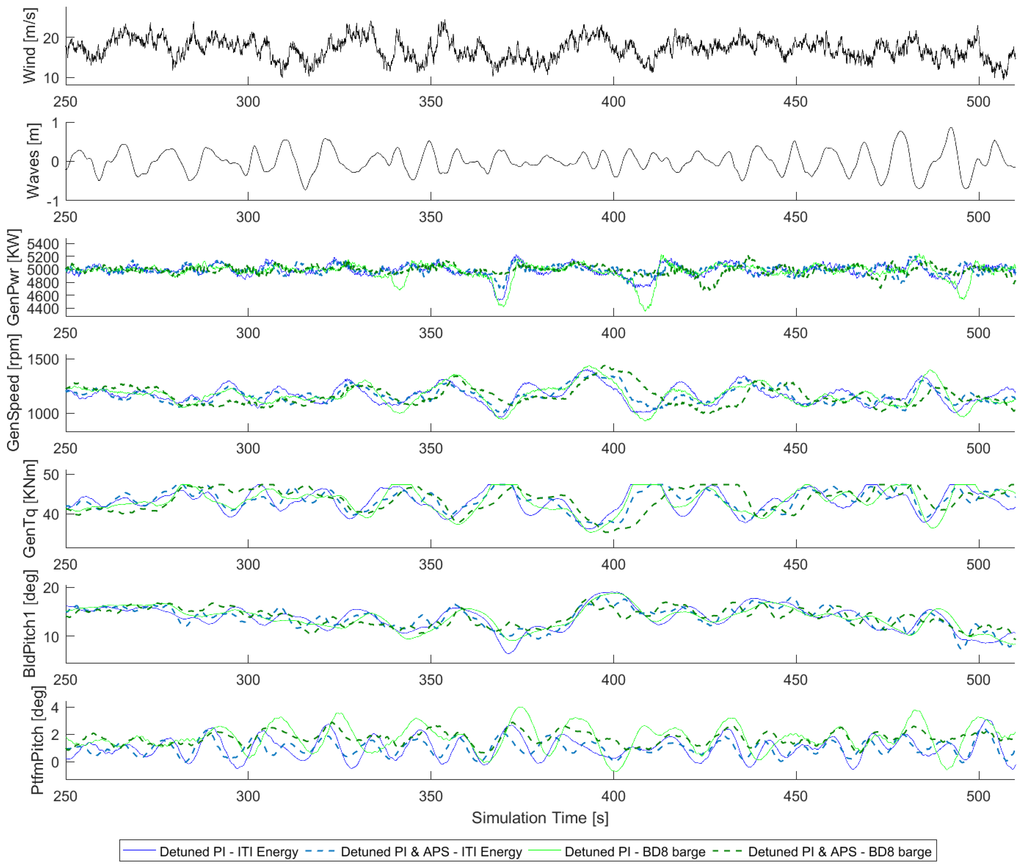
Time domain simulations were carried out to test the NREL 5 MW wind turbine mounted on the two barges presented in
Section 2 with the implementation of the control techniques presented in
Section 3. The wind profile has been generated with TurbSim v1.06.00 for the Design Load Case (DLC) 1.1 (power production) as defined by the standard IEC61400-1 [
27]. The most turbulent wind case scenario has been selected (wind turbine class—A) to demonstrate the vigorous blade-pitch PI control response to wind gusts. The irregular waves have been generated with the HydroDyn module and the JONSWAP/Pierson–Moskowitz spectrum model. The selected most probably wave-elevation case scenario is about 1.37 m as the standard deviation of the Gaussian-distributed histogram shows in [
11]. The selected peak-shape spectral period of the incident waves is about 12.4 s, the worst case frequency to excite the platform-pitch motion of the proposed platforms as shown in
Figure 3. Note that all the simulations were carried out with Matlab/Simulink (R2016b) (MathWorks, Natick, MA, USA) linked with FAST v8.16.00a (AeroDyn v15.00 (NREL, Golden, CO, USA) and HydroDyn v2.03 (NREL, Golden, CO, USA)).
The simulations were repeated from 13 m/s to 25 m/s mean wind speed, each 2 m/s.
Figure 8 shows an overview of the time domain results of the most representative FOWT variables at 17 m/s. Although the duration of the full simulation is 1000 s, only 250 s are shown in order to make clear the visualization. One can see that the best performance is achieved by the ITI Energy barge with the implementation of the APS control technique. This FOWT system model shows a good generator speed regulation and the lowest platform-pitch oscillations as well as the best generator power production quality. The generator torque also shows a softer regulation due to the improvement in the generator speed regulation. Note that all these improvements have been possible without increasing the blade-pitch activity.
Good improvements are also shown by the BD8 barge model with the implemented APS control technique. In this context, the power production presents better quality than the conventional blade-pitch detuned PI control with the same platform system. The generator speed regulation is very similar to the ITI Energy barge model with the APS control technique implemented as predicted by the bode diagram of
Figure 6. Platform-pitch oscillations are reduced with the implementation of the APS control technique on the basis that more compact barge models present higher static platform-pitch inclination as predicted by
Figure 2.
Although the FOWT performance improvement can be seen during all the simulation times, the effect of the APS control technique is more evident when the drops in the electric power production occur. One can see how the APS controller reacts a few seconds earlier than the conventional detuned PI controller and changes the blade-pitch angle faster in these time intervals. This early reaction reduces the thrust in the rotor, and, as a consequence, the platform-pitch oscillations, resulting in a more stable generator speed regulation and power production quality.
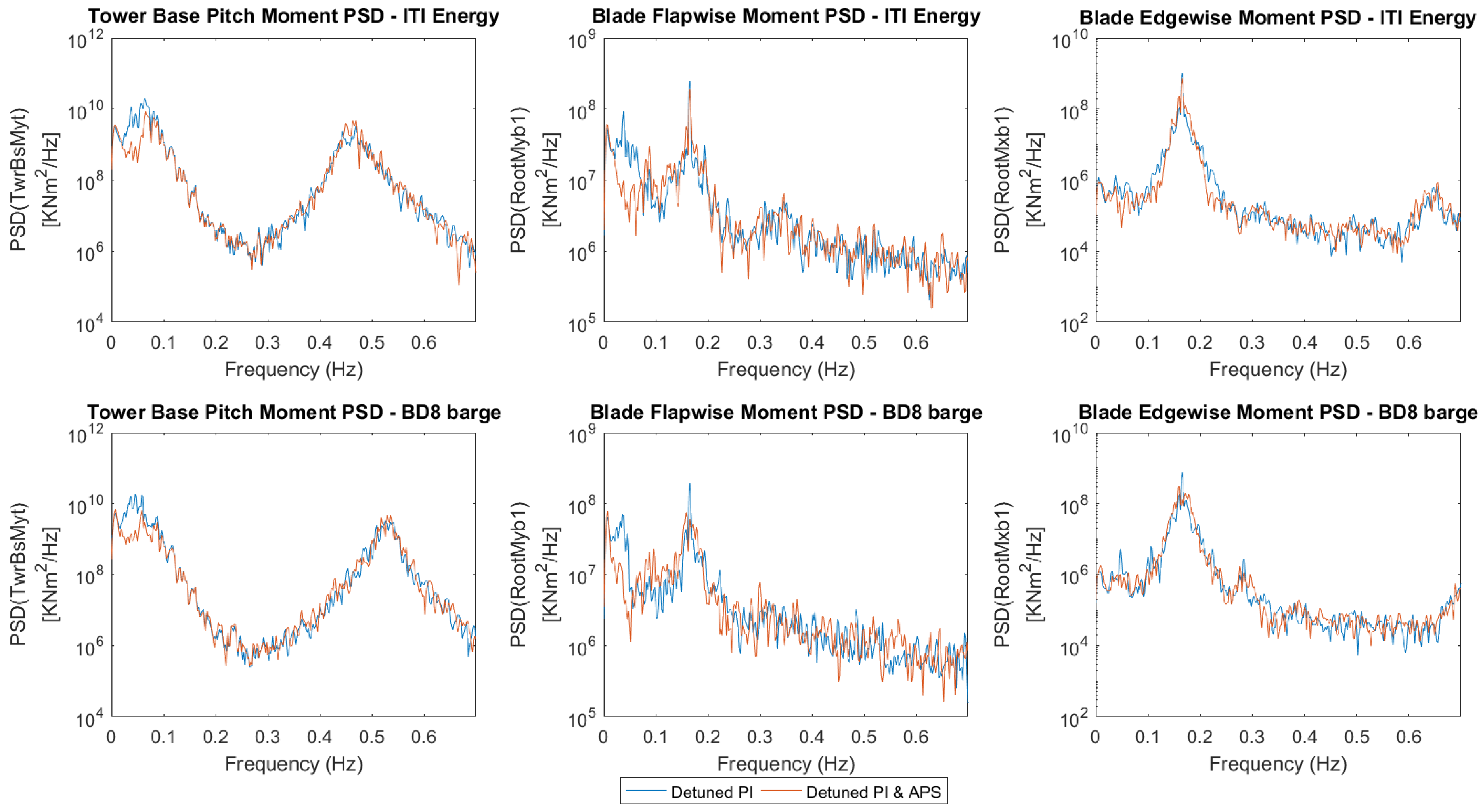
5. Load Analysis
Figure 9 shows the Power Spectral Density (PSD) of the blade-root and the tower-base bending moments obtained at 17 m/s mean wind speed simulation with the four combinations of the barges and control configurations studied in this paper. The PSD analyses are not carried out with the overall simulation time (1000 s), and the first 100 s are not considered to avoid the transitions of the start up. Appreciable improvement is achieved at low frequencies via the APS control technique, even with the BD8 barge. The rotational speed frequency (1P = 0.2 Hz) is not affected as well as the blade passing frequency (3P). The blade-root flapwise bending moments are smaller due to the reduction in the rotor thrust thanks to the vigorous blade-pitch reaction, whereas the tower-base pitch bending moments are smaller due to the reduction in the platform-pitch oscillations. The blade-root edgewise bending moments are not affected by the implementation of this APS control technique.
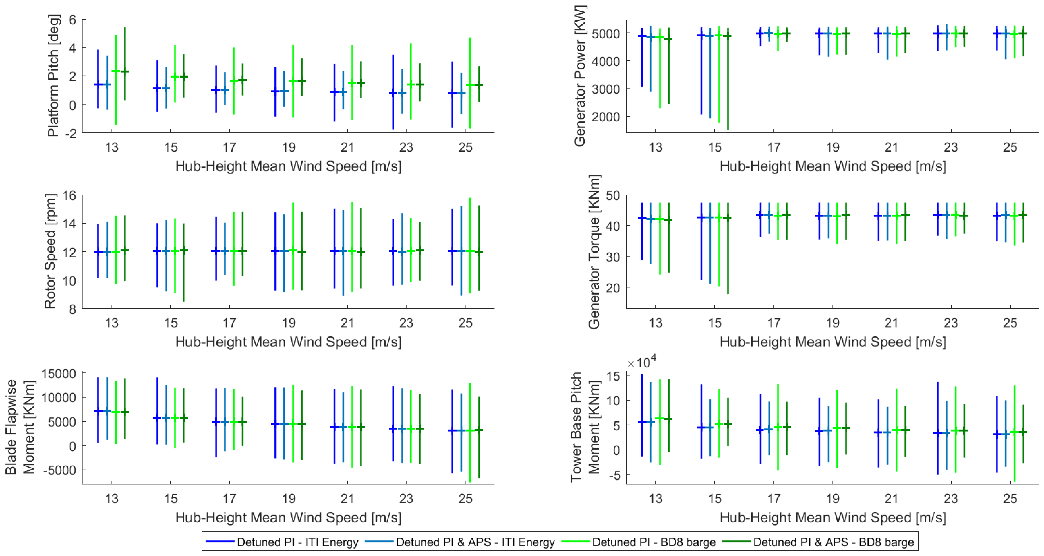
Figure 10 shows the candlestick chart of the most representative FOWT system behaviour parameter values for the validation of the previously presented APS control technique. This analysis has been repeated throughout the overall range of above rated wind speeds.
The platform-pitch results (top left) show great oscillation reductions in both barge systems thanks to the implementation of the APS control technique. This improvement gets more important as the wind speed is higher due to the limitation in the speed reaction of the conventional blade-pitch detuned PI control. Note that the BD8 barge oscillations with the APS control technique implemented are even smaller than those of the ITI Energy barge with the conventional blade-pitch detuned PI control from 17 m/s wind speed upwards. Such a fact is relevant considering that the more compact barge model has higher static platform-pitch oscillations, as it can be checked by the mean value.
This improvement can be also seen in the tower-base bending moment analysis (bottom right plot), where the bending moment reduction is effective for the overall wind speed range. The improvements are more visible with higher wind speeds due to the limitation of the conventional blade-pitch detuned PI control reaction. Note that the BD8 barge with the APS control technique shows the narrowest spread between the minimum and the maximum values even comparing with that obtained with the ITI Energy barge with the conventional blade-pitch detuned PI control.
This FOWT performance improvements are not damaging the blades of the wind turbine more than the conventional blade-pitch PI control does, as it can be checked in the results depicted by the blade-root flapwise plot (bottom left). In this context, the bending moments presented by the APS control FOWT model are lower than that presented by the conventional blade-pitch detuned PI control for all wind speed cases. Furthermore, those bending moments shown by the BD8 barge with the APS control technique are even lower than the presented by the ITI Energy barge with the conventional blade-pitch detuned PI control technique.
The power production and the rotor speed regulation are also improved thanks to the APS control technique from 17 m/s wind speed upwards, as one can see in the corresponding plot of
Figure 10. Note that, at 13 m/s and 15 m/s, the control switching between the torque and the blade-pitch control regions slightly affects the APS control loop performance. This is because the APS control loop is sometimes suddenly deactivated when the conventional blade-pitch detuned PI control loop demanded angle reaches 0
. This may be avoided by limiting the APS control loop blade-pitch rate or introducing a kind of hysteresis for this transition zone. Different possibilities are currently being studied in this context.
6. Results Summary
The ITI Energy barge with the implementation of the proposed APS control technique shows the best performance. The best generator speed regulation as well as the lowest platform-pitch oscillations are shown, not being detrimental to the blade-pitch activity while reducing blade-root and tower-base bending moments. Furthermore, the best power production quality is also shown for the overall wind speed range.
Furthermore, it is also demonstrated that the proposed APS control technique has the potential to improve the performance of the conventional blade-pitch detuned PI control mounted on the more compact platform BD8 barge, which has less hydrodynamic stiffness and presents a higher static platform-pitch inclination than the original ITI Energy barge. The generator speed regulation as well as the platform-pitch oscillation have been improved in most of the wind speed cases. This was possible without a relevant increment in the blade-pitch activity and with a considerable reduction in blade-root and tower-base bending moments thanks to the early blade-pitch reaction to wind gusts.
7. Conclusions
A new APS control technique is presented in this work for five MW FOWT systems mounted on barge platforms. Performance improvements have been presented on the ITI Energy barge model. Better generator speed regulation and lower platform-pitch oscillations have been achieved, while not increasing the blade-pitch activity and reducing blade-root and tower-base bending moments. Electric power production quality has also been improved.
The potential of this control technique to improve FOWT systems based on more compact platforms has been also demonstrated. Not only has the generator speed regulation been improved and the blade-root and tower-base loads been reduced, but the performance deterioration caused by the hydrodynamic stiffness reduction, due to the more compact platform, has been mitigated as well.

 ,
, 


