Article

Design Method of Controllable Blade Angle and Orthogonal Optimization of Pressure Rise for a Multiphase Pump

State Key Laboratory of Hydroscience and Engineering, Department of Energy and Power Engineering, Tsinghua University, Beijing 100084, China
*
Author to whom correspondence should be addressed.
Energies 2018, 11(5), 1048; https://doi.org/10.3390/en11051048
Submission received: 29 March 2018 / Revised: 13 April 2018 / Accepted: 14 April 2018 / Published: 25 April 2018

Abstract

:
The hydraulic design method of controllable blade angle for rotodynamic multiphase pump with impeller and diffuser is proposed. The distribution of blade angle along the meridional streamline is governed by the normalized fourth-order and first-order polynomial function for impeller and diffuser, respectively. The orthogonal optimization method with five factors and four levels is employed by numerical simulation to optimize the geometry parameters, including the shroud angle at the leading and trailing edge βIs0, βIs1, the blade difference at inlet ∆βI0, and the coefficients at hub and shroud kh, ks. According to orthogonal analysis, the influence of each factor on pressure rise is estimated, and the optimization values of for those parameters are determined. The pressure rise of optimization multiphase pump is increased by 12.8 kPa in comparison of the base pump. Results show that the distributions of gas volume fraction (GVF) and the pressure become more uniform after optimization, which improves the transporting performance of the multiphase pump.

1. Introduction

The exploration and utilization of nature sources in deep sea have become an important issue with the increasing demand of power source. Multiphase pump is a widely used piece of equipment in petroleum industry for offshore plant, which pressurizes and transports the mixture of oil and gas. However, due to the complicated interactions between the liquid phase and gas phase, the efficient transporting of multiphase flow still requires further investigation.
The technique of multiphase pump was firstly proposed and tested in 1990s, and it can be classified into two major categories, including screw pump and rotodynamic pump. The screw pump transports the fluid by the volume variation of seal chamber between screws and bushing, which is applied in the condition of high gas volume fraction and is sensitive to the solid particles. Dal Porto et al. [1] introduced the trial of twin-screw pumps in Gulf of Mexico and Alberta in Canada. Field applications validated the reliability of multiphase pumps in handling slugs, but the low efficiency of this type pump restricted their wide application. Rabiger et al. [2] carried out theoretical and experimental analysis on a multiphase screw pump with high gas volume fractions, and leakage flows through the circumferential gaps were observed. For the other type of rotodynamic pump, it transports energy to the fluid by the rotating impeller, and it has advanced performance because of its high efficiency and pumping of particle. Cao et al. [3] carried out experiment study on the performance of rotodynamic multiphase pump. The experimental results showed that the pump could operate in a wide range with the highest efficiency of 44.0%. The flow fileds inside the rotodynamic multiphase pump had been studied by means of high-speed photography technique [4,5]. Experimental observation showed that the mean diameter of the bubbles at the inlet section would increase when the inlet gas volume fraction increased, while the mean diameter decreased with the increasing of rotation speed. Typical flow patterns, including isolated bubbles flow, bubbly flow, gas pocket flow, and segregated flow, appeared in sequence with the increasing of inlet gas volume fraction. Among these flow patterns, the gas pocket flow was the most common one and had significant influence on the hydraulic performance of the multiphase pump [6]. It was found that the gas pocket would form at the suction surface and then moved towards the pressure surface downstream.
The experimental research of hydraulic machinery is always time-consuming and costly due to its complexity, and the Computational Fluid Dynamics (CFD) method has become an effective tool in the investigation [7,8,9]. When compared with single phase flow, the numerical simulations of multiphase flow are much more complicated in account of the interphase interactions between liquid phase and gas phase. Yu et al. [10] compared the numerical results of homogeneous model and two-fluid model, and found that the latter one was more reasonable and accurate because the effect of interphase forces was taken into consideration. To study the magnitude of different interphase forces, four types of forces were considered overall, involving drag force, lift force, virtual mass force, and turbulent dispersion force in the numerical simulations [11,12]. Results showed that the drag force was dominant inside the impeller, while the turbulent dispersion force was almost negligible. In addition, the lift force and virtual mass force were larger or smaller than the drag force, depending on inlet gas volume fraction and location.
Because of the importance of rotodynamic multiphase pump in petroleum industry, various studies have been conducted to optimize its structure and improve hydraulic performance. Since the nonlinear relation between geometry parameters and hydraulic performance is complex, various optimization methods have been introduced for the study of multiphase pump, such as genetic algorithm [13,14,15], response surface method [16,17], and the central composite method [18]. Zhang et al. [13] developed a multi-objective optimal method by combining the non-dominated sorting genetic algorithm-II (NSGA-II) and artificial neural network (ANN), and the pressure rise and efficiency of optimized pump were improved by 10% and 3%, respectively, in comparison of the original pump. Kim et al. [16] applied the design of experiment (DOE) technique to organize the optimization procedure, and the optimization results were obtained by means of response surface method (RSM). By optimization, the pressure rise and the efficiency were increased by 30.9 kPa and 1.9%, respectively. Numerical results of the internal flow fields indicated that the optimized pump could suppress the non-uniform flow components.
The above optimization methods, which can be collectively called intelligent algorithms, always require hundreds of test cases and consume large amount of resources. The orthogonal method is introduced to reduce the cost in the present research, which was developed by Byrne and Taguchi [19]. According to the orthogonal method, the parameters are arranged to meet the principle of orthogonality, and hence the number of test cases can be reduced to achieve efficient optimization. Many investigations [20,21,22,23,24] have validated the reliability of the orthogonal method on the optimization of hydraulic machinery.
When compared with various studies on optimization, the design method for rotodynamic multiphase pump is relatively rare. The pump geometry is mainly developed according to previous experience, which is highly sensitive for different situations. Cao et al. [3] have proposed a hydrodynamic design method for the impeller of multiphase pump by means of a combined approach of inverse design and CFD analysis. According to this method, the geometry of impeller was determined by specified velocity torque distribution. The three-dimensional hydraulic method was also employed by Zhang et al. [25], and it was effective to suppress the performance decline under large flow rate. For rotodynamic multiphase pump, a diffuser is always equipped after an impeller to recover the kinetic energy from fluid and adjust the flow direction. The impact at diffuser inlet can be reduced and the flow pattern inside diffuser can be promoted when the geometry at the impeller outlet and diffuser inlet is matched. However, the previous design method mainly focuses on the impeller and the design for diffuser remains empirical. In the present research, a design method for the impeller and diffuser of the rotodynamic multiphase pump is proposed based on the controllable blade angle, and the geometry parameters are optimized by the means of the orthogonal method.

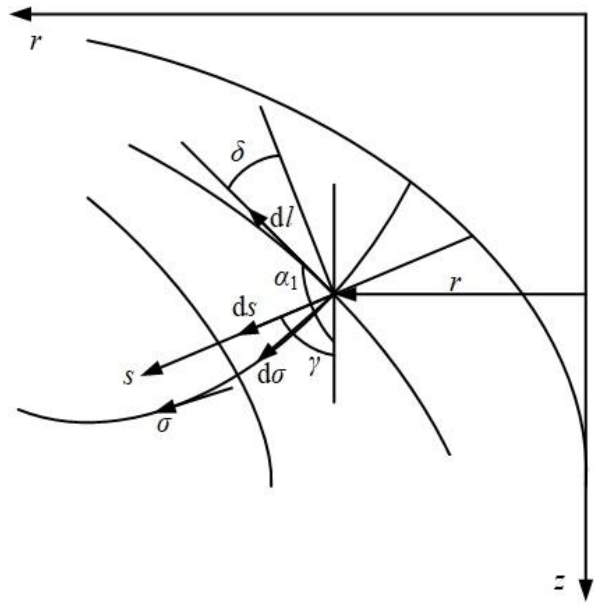
2. Design Method Based on Controllable Blade Angle

Traditionally, the impeller and diffuser of rotodynamic multiphase pump are designed empirically, which requires a large amount of trail tests. In the current study, a design method based on controllable blade angle is introduced, which derives from the design method of inlet guide vanes in centrifugal pump [26]. According to the proposed design method, the blade geometry can be determined by the distribution of blade angle along meridional flow.
First, the meridional flow is determined by means of streamline curvature method. The gradient equation of meridional velocity cm along the quasi-orthogonal curve s can be expressed by:
d c m d s = P ( s ) c m
P ( s ) = ( d α 1 d s sin δ α 1 l ) 1 cos δ ( sin α 1 r + ln χ l ) sin δ
where l and r denote the meridional streamline and the radius, α1 is the angle between the tangential of meridional streamline and the axial line, and δ is the angle between the normal of quasi-orthogonal curve and the tangential of meridional streamline, and χ is the blockage coefficient, as shown in Figure 1.
The general solution of the above gradient equation is as follows:
c m ( s ) = c m c exp ( s c s P ( s ) d s )
where cmc is a constant determined by the following continuity:
c m c = Q s h u b s s h r 2 π r χ exp ( s h u b s P ( s ) d s ) cos δ d s
where Q is the volume flow rate, and subscripts shr, hub denote the shroud and the hub, respectively.
On the assumption that the flow rates are equal inside each sub-flow channel, the result of meridional velocity can be calculated by solving the Equation (1) in order to determine the flow net. Then, the three-dimensional geometry of blade can be determined according to the bone line differential equation:
d θ = 1 r tan β d l
where θ and β are wrap angle and blade angle, respectively.
The above flow equations can be referred in Ref. [26] for detail. Since the meridional streamline l and the radius r can be determined by the solved flow net, the key factor of hydraulic design is to determine the distribution of blade angle β along the meridional streamline. The blade angle distribution along the meridional streamline from inlet to outlet can be normalized, as follows:
β = β 0 + Δ β f ( x ) ,   0 < x < 1
where x denotes the relative meridional streamline, and values of 0 and 1 represent the leading edge and trailing edge, respectively. β0 is the blade angle at the leading edge, and ∆β = β1β0 is the difference between the blade angle at trailing edge and the leading edge.
In the present design method, polynomial functions are employed for the blade of impeller and diffuser. For blade of impeller, a normalized fourth-order polynomial function is applied since there are four given conditions and one unknown condition. It can be expressed by:
f ( x ) = a x 4 + b x 3 + c x 2 + d x + e
where a, b, c, d and e are coefficients, and five conditions are required to calculate these coefficients.
(1)
The blade angle at the leading edge: β | x = 0 = β 0 , corresponding to f ( 0 ) = 0 ;
(2)
The blade angle at the trailing edge: β | x = 1 = β 1 , corresponding to f ( 1 ) = 1 ;
(3)
The non-incidence condition at the leading edge: d β d x | x = 0 = 0 , corresponding to d f ( x ) d x | x = 0 = 0 ;
(4)
The Kutta-Joukowsky condition at the trailing edge: d β d x | x = 1 = 0 , corresponding to d f ( x ) d x | x = 1 = 0 ;
(5)
The value of f(x) at middle point of relative meridional streamline x = 0.5 is given as k.
Taking account of the above five conditions, the coefficients of f(x) can be obtained, as follows:
{ a = 16 k 8 b = 14 32 k c = 16 k 5 d = 0 e = 0
According to Equation (8), the normalized fourth-order polynomial function f(x) can be determined by the given value of k.
For diffuser, the normalized polynomial function is simply set as proportional function of f(x) = x, which is a first-order polynomial function, because uniform blade loading is required to suppress flow separation due to the powerful rotation of inflow.
Generally, the geometry parameters at the hub and shroud of blade are given as initial parameters, including blade angles βIh0, βIs0, βIh1, βIs1, βDh0, βDs0, βDh1, βDs1, and k-coefficient kh, ks, where the subscript I and D denote the impeller or diffuser, h and s denote the hub and shroud, 0 and 1 denote the leading edge and the trailing edge, respectively.
Additional conditions should be added to determine these ten geometry parameters, as follows:
(1)
Identical wrap angle at impeller outlet should be met to suppress the gas-liquid separation due to centrifugal force, which satisfies the following equation:
0 l 1 r tan β d l = constant
(2)
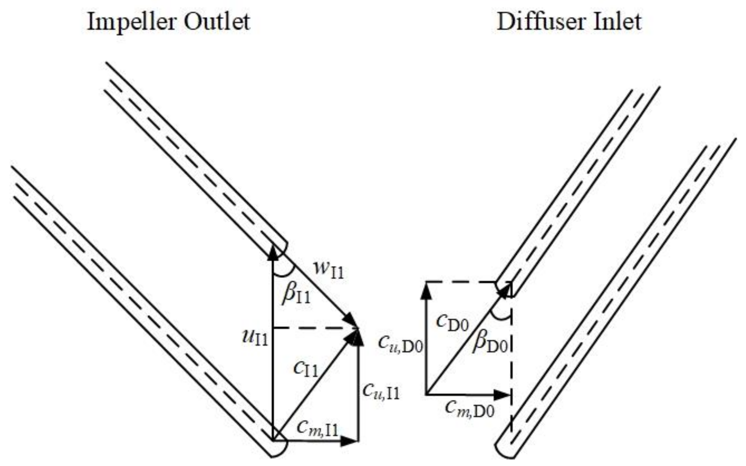
Supposing uniform velocity moment between impeller outlet and diffuser inlet because of none extra velocity moment in the vaneless region, βDh0 and βDs0 can be determined, as shown in Figure 2:
( u I 1 c m , I 1 / tan β I 1 ) r I 1 = ( c m , D 0 / tan β D 0 ) r D 0
where c, w, u are absolute velocity, relative velocity and circumferential velocity, respectively. cu and cm are the circumferential and meridional component of absolute velocity.
(3)
Axial outflow for diffuser is required, so the values of βDh1 and βDs1 are set as 90°.
According to the above additional conditions, only five geometry parameters need to be given initially for this design method, which are βIh0, βIs0, βIs1, kh, and ks. So far, the hydraulic design method for the blades of impeller and diffuser has been completed, and the initial given parameters of βIh0, βIs0, βIs1, kh, and ks will be optimized in the present research.

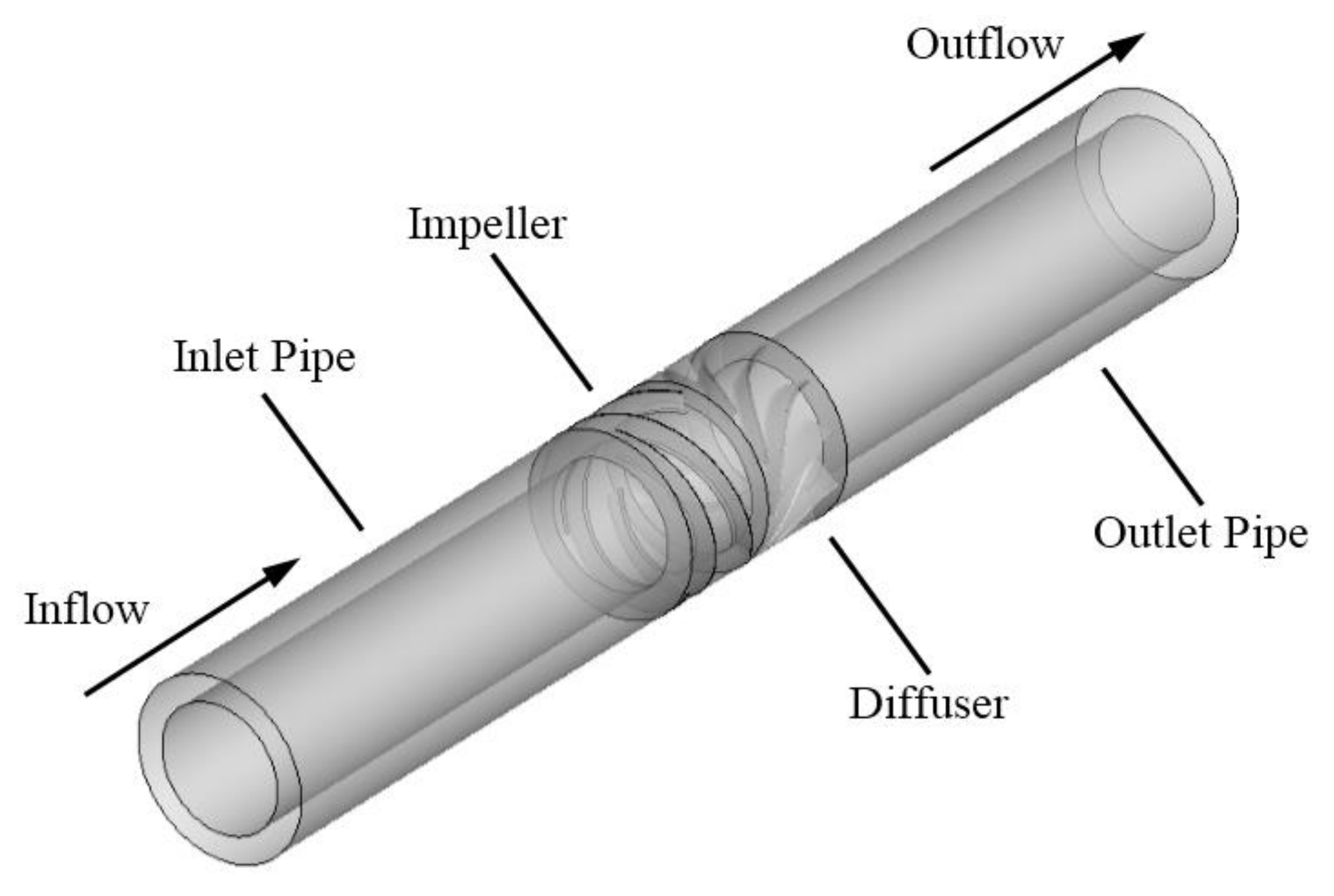
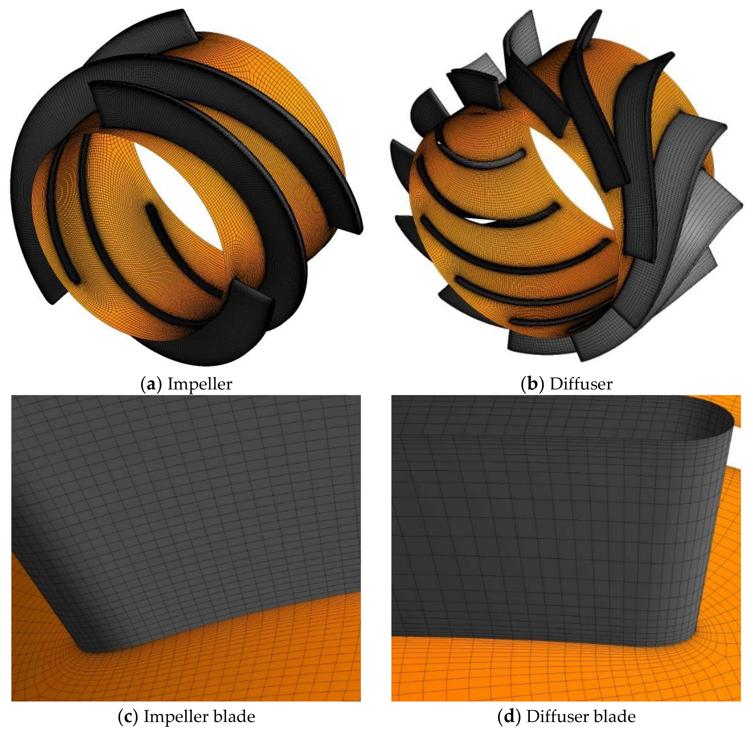
3. Physical Model and Computational Domain

In order to validate the reliability of the hydraulic design method and optimize the initial parameters, a rotodynamic multiphase pump of Kim [16] is selected as the base pump in the present research. For multi-stage pump, though the flow conditions at different stage inlets are different, the work capability for each stage is nearly the same. So, the design method for single stage pump can be applied for the multi-stage pump, and the special attention should be paid on the matching between diffuser outlet and impeller inlet of next stage. The design parameters and the major geometry parameters are shown in Table 1 and Figure 3. The experimental investigations have been carried out by Kim to evaluate the pump performance, and the results are employed in the present research to validate the accuracy of numerical simulation.
As shown in Figure 4, full passage simulation is conducted on a single stage multiphase pump. The computational domain consists of inlet pipe, impeller, diffuser, and outlet pipe. The ANSYS ICEM 14.5 is employed to generate the structured mesh for the inlet pipe and the outlet pipe, and the ANSYS TurboGrid 14.5 is applied to generate the structured mesh of impeller and diffuser because of its specialty for turbomachinery. The mesh near the wall surface is locally refined to capture the flow inside the boundary layers, as depicted in Figure 5.

4. Numerical Methods and Settings

4.1. Numerical Method

The ANSYS CFX 14.5 is employed to solve the three-dimensional turbulent gas-liquid multiphase flow. The inhomogeneous two fluid model is applied to simulate the multiphase flow, which is a kind of Eulerian-Eulerian approach. The Particle Model for momentum transfer is employed, which assumes the liquid phase of water and the gas phase of air as continuous fluid and dispersed spherical fluid, respectively. Then, the Dispersed Phase Zero Equation and Shear Stress Transport (SST) k-ω turbulence model are applied for the gas phase and liquid phase, respectively. Both Dispersed Phase Zero Equation and Shear Stress Transport (SST) k-ω turbulence model are eddy viscosity model, the eddy viscosity by SST k-ω model can be determined, according to Ref. [27], and eddy viscosity by Dispersed Phase Zero Equation is defined, as follows [28]:
μ t d = ρ d ρ c μ t c Pr t
where μt is eddy viscosity, ρ is density, Prt is turbulent Prandtl number, and the subscript c,d denote continuous phase and dispersed phase, respectively. The effect of fluid buoyancy is also taken into account by the density difference method.
The interphase forces are key factors affecting the accuracy of numerical analysis. The Grace Drag Force model is employed in the numerical simulation to calculate the interphase model between water and air. The Grace Drag Force model is specially developed based on air-water data, and it is effective for air-water flow fields. The drag force coefficient cD of Grace Drag Force model can be expressed as follows [29]:
c D = 4 3 g d U T 2 Δ ρ ρ c
where g is the gravitational acceleration, d is the mean diameter, ∆ρ is the density difference between phases, UT is the terminal velocity, and it can be given by:
U T = μ c ρ c d p M 0.149 ( J 0.857 )
where μ is dynamic viscosity, M is the Morton Number:
M = μ c 4 g Δ ρ ρ 2 σ 3
J = { 0.94 H 0.757 2 < H < 59.3 3.42 H 0.441 H > 59.3
H = 4 3 E o M 0.149 ( μ c μ ref ) 0.14
E o = g Δ ρ d p 2 σ
where μref = 0.0009 kg/(m·s), which is value for water at 25 °C and 1 bar, σ is the surface tension coefficient with value of 0.073 N/m.
Non-drag interphase forces such as lift force, virtual mass force, wall lubrication force, and turbulent dispersion force have not been considered in the present research, since their influence is limited when compared with the drag force and strong centrifugal force. In addition, the turbulence enhancement due to wakes behind particle is taken into account by the Sato Enhanced Eddy Viscosity method [30].
The boundary conditions consist of imposed static pressure at pump inlet, a given mass flow rate at pump outlet, and no slip condition at wall surfaces. Because of the significance of tip clearance on pump performance [31,32,33], it has been taken into consideration in the study. The condition of counter rotating wall is added at the shroud of impeller to simulate the stationary shroud wall. During multiphase flow simulation, the value of gas volume fraction (GVF) is imposed at the pump inlet. For the whole computational domain, the impeller is rotational while the others are stationary, and the frozen rotor method is used to connect the rotational domain and the stationary domain.

4.2. Independence Test of Mesh Number

Totally four sets of mesh are employed to conduct the independence test of mesh number, with the number of mesh elements varying from 3.85 × 10⁶ to 6.40 × 10⁶. Table 2 lists the predicted results of pressure rise and efficiency of multiphase pump at GVF = 0 and 10% under the design flow rate. For numerical simulation of pump, the mesh element should be sufficient to guarantee the accuracy. In the independence test, the meshes of impeller and diffuser change, while the meshes of inlet and outlet pipes remain the same, because the impeller and diffuser are the key components of power and energy conversion. According to the numerical results, the predicted values become almost stable when mesh number exceeds 4.76 × 10⁶, with the maximum variation of 0.55%. Therefore, the Mesh 2 with 4.76 × 10⁶ elements is applied in the following research.

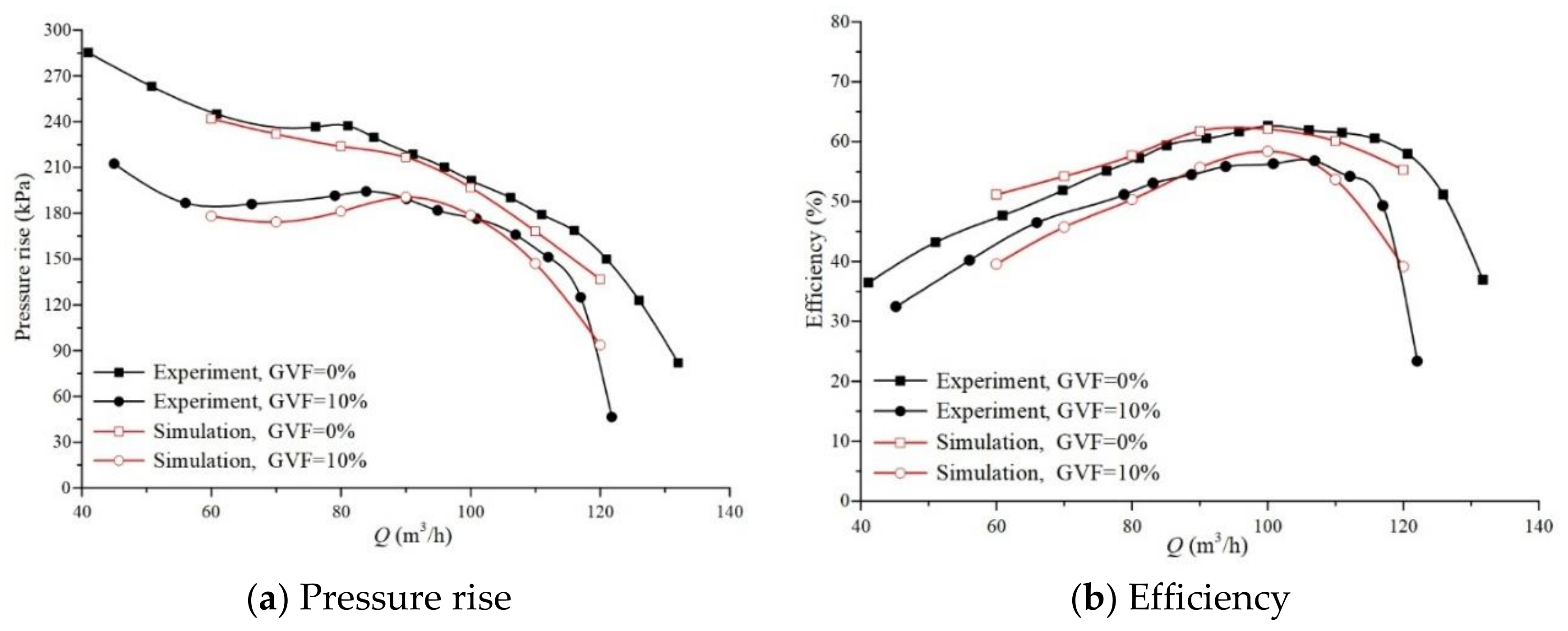
4.3. Simulation Accuracy Validation

The numerical results are validated by the experimental measurements of Kim [16], where the measurement uncertainty of efficiency is no more than 0.48%. Operating conditions under seven flow rates (Q = 60, 70, 80, 90, 100, 110, and 120 m3/h) and two inlet gas volume fractions (GVF = 0, 10%) are simulated, according to the experimental measurements of Kim [16]. Figure 6 depicts the comparison of experimental measurements and the numerical simulations on pressure rise and efficiency. It can be found that the numerical results are in good agreement with experimental measurements, especially within the range near the design flow rate. Under design flow rate with 10% gas volume fraction, the relative errors of pressure rise and efficiency are 1.41% and 3.68%, respectively.

5. Orthogonal Optimization Design

5.1. Optimization Design Parameters

According to the design method based on controllable blade angle proposed in Section 2, overall, five geometry parameters need to be determined in this design method, including hub blade angle at the leading edge of impeller βIh0, the shroud angle at the leading edge of impeller βIs0, the shroud angle at the trailing edge of impeller βIs1, and the k-coefficient at the hub and the shroud of impeller blade kh, ks. Based on the principle of uniform wrap angle for impeller, the blade angle near hub should be larger than that near shroud at impeller inlet. In order to meet this requirement in the optimization procedure, a parameter of blade difference at impeller inlet ∆βI0 = βIh0βIs0 is introduced.

5.2. Orthogonal Table

An orthogonal table with five factors and four levels for each factor is established and is denoted as L16(45). In the orthogonal method, only 16 individual tests are required to cover the five factors and four corresponding factor levels, which is remarkably less than original individual tests of 45 (=1024). By referring to the base pump of rotodynamic multiphase pump in reference [16], the factor levels are selected, as shown in Table 3. Table 4 lists the L16(45) orthogonal table for optimization, which is determined to meet the principle of orthogonality.

6. Result and Discussion

6.1. Orthogonal Analysis

Totally, 16 tested rotodynamic multiphase pumps with different impeller and diffuser, and the same inlet pipe and outlet pipe are numerically simulated. Table 5 lists the predicted pressure rise under design flow with inlet gas volume fraction of 10%.
The orthogonal analysis method is introduced to evaluate the influence of each specific parameter, and the average value k ¯ i is employed and defined, as follows:
k ¯ i = 1 N j = 1 N Δ p j
where subscript i denotes the specific level of the parameter, ∆p is the predicted pressure rise of tested pumps with corresponding parameter and at corresponding level i, and N is the total number of tested cases with corresponding parameter and at corresponding level. The range R is applied to estimate the magnitude of influence of each parameter, which is determined by the difference between maximum k ¯ i and minimum k ¯ i for corresponding parameter, as follows:
R = max { k ¯ i } min { k ¯ i } ,   i = 1 , 2 , 3 , 4
According to the results of orthogonal analysis in Table 6, the magnitude of influence for pressure rise can be sorted by: βIs0 > ks > kh > ∆βI0 > βIs1. It can be found that the parameter βIs0 is the most significant parameter for pressure rise, and βIs1 is the least important parameter.

6.2. Orthogonal Optimization

The value of specific parameter can be determined based on the orthogonal results in Table 6. In the present research, the major objective is to improve the pressure rise of multiphase pump, which is significant for the transport of the gas-liquid mixture. The values for each parameter are: βIs0 = 8, ∆βI0 = 3.5, βIs1 = 23, kh = 0.6, and ks = 0.6. Figure 7 shows the blade angle distribution along the relative meridional streamline in the base and optimization pumps, and Figure 8 displays the corresponding three-dimensional structure.

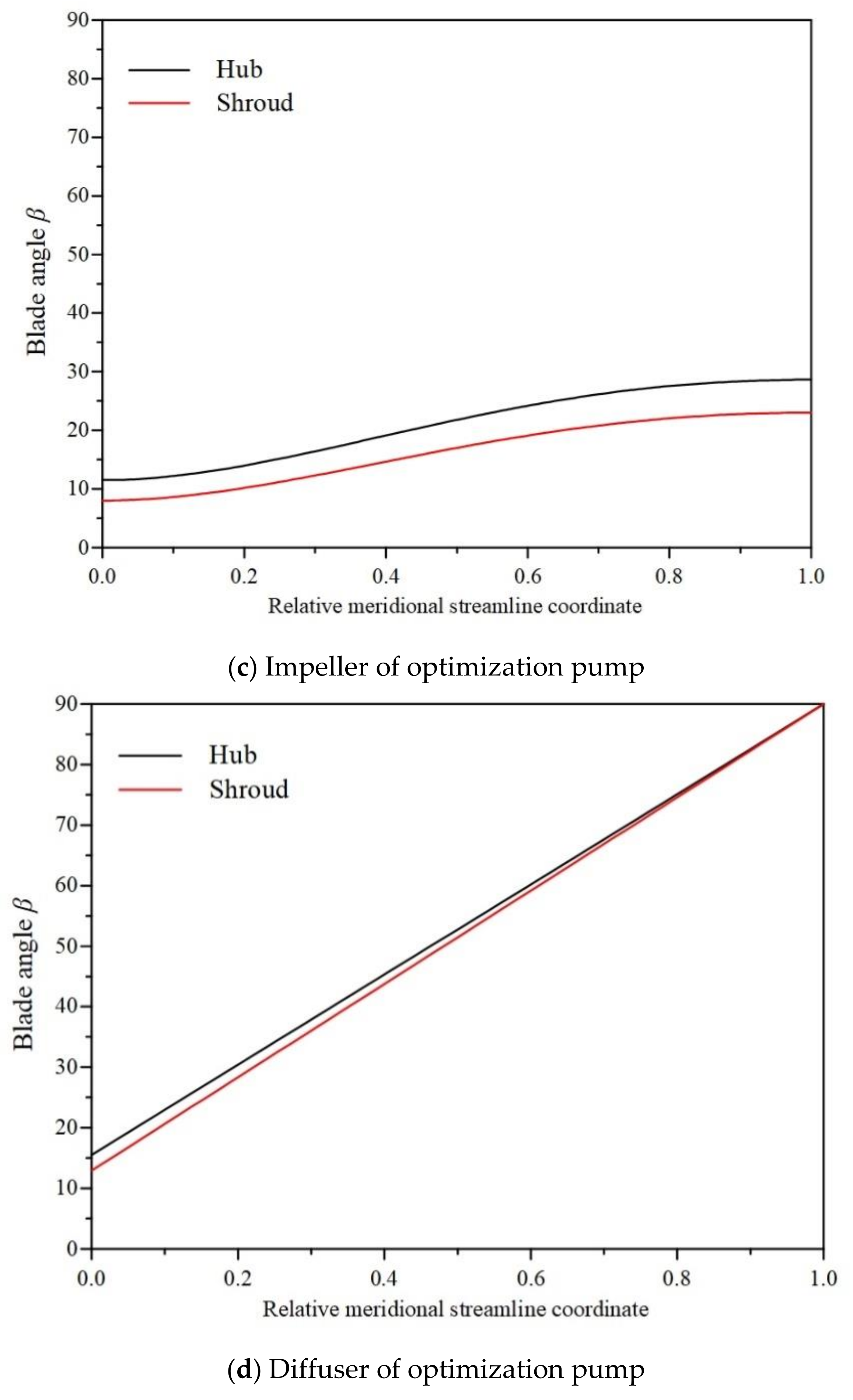
6.3. Optimization Results

Based on the orthogonal optimization method, the optimization geometry parameters can be obtained. Under design flow rate with 10% inlet gas volume fraction, the pressure rises for base pump and optimization pump are 178.81 kPa and 191.62 kPa, respectively. The pressure rise improves by 6.69%, which validates the reliability of design method and the optimization strategy for multiphase pump that is proposed in the present research.
The Eulerian equation can be employed to analyze the pressure rise of multiphase, which is defined by:
Δ p t h = ρ m ω ( c u 1 r 1 c u 0 r 0 )
where ∆pth is the theoretical pressure rise, ω is the angular velocity of impeller. The Equation (19) can be converted into the following form:
Δ p t h = ρ m ω ( c m 1 r 1 tan β I 1 c m 0 r 0 tan β I 0 )
According to Equation (20) it can be found that larger outlet blade angle and smaller inlet blade angle will lead to a higher theoretical pressure rise, which explains the reason for the optimization values of blades angles in orthogonal analysis. For βIs1, it is obvious that higher value can lead to better pressure rise. In account of the condition of uniform wrap angle in Equation (9), higher βIs0 will result in larger wrap angle and therefore the higher value of βIh1 is determined. For ∆βI0, because the value of βIh1 is obtained by βIs0 − ∆βI0, higher value of ∆βI0 can result in a lower value of lower hub blade angle at the leading edge of the impeller. Due to larger growth rate of tangent function (tan) at high values, the effect of βI1 (approximately 20°) is more significant than βI0 (approximately 7°) for pressure rise. Therefore, the higher value of the blade angle at the trailing edge is in more urgent demand than that at the leading edge.
In order to investigate the mechanism of pressure rise improvement for optimization pump, the internal flow fields inside base pump and the optimization pump are illustrated and compared. Because of the density difference between the liquid phase and the gas phase, the gas phase tends to move towards shroud while the liquid phase accumulates at the hub under the effect of strong centrifugal force. In account of the radial difference from hub to shroud, three typical sections at 5%, 50%, and 95% blade height are selected to show the internal field of multiphase pump.
Figure 9 shows the distribution of gas volume fraction GVF at sections of 5%, 50%, and 95% blade height inside base pump and optimization pump. Firstly, the distribution of two phase mixture becomes more uniform at the vaneless space between impeller and diffuser in the optimization pump. This uniform distribution indicates a fully blending at this region, which is beneficial for the recovery of kinetic energy in the diffuser. Secondly, the partially high GVF region at diffuser inlet is suppressed. This accumulated gas pocket will block the passage and further affect the normal flow. Thirdly, the scope of gas phase along the pressure side of impeller shroud is also reduced. Above all, it can be concluded that the optimization geometry of impeller and diffuser makes for a uniform distribution of gas-liquid mixture, which reduces the blockage inside the passage.
Figure 10 shows the distribution on the blade surface of impeller, including Pressure Surface (PS) and Suction Surface (SS). On the blade pressure surface of impeller, a triangle-shaped narrow gas pocket can be observed near the leading edge, with an edge parallel to the impeller inlet and a small angle towards the impeller outlet. After the optimization, the region of the triangle-shaped gas pocket has been reduced, with the end point advanced from about 2/3 chord length to almost 1/2 chord length. By contrast, on the blade suction surface, the distribution of GVF is much more complicated. A visible region with high volume fraction of gas phase occurs at the leading edge and then decreases towards about 1/3 chord length. Afterwards, the volume fraction of gas phase increases gradually and the gas phase begins to occupy the whole passage. At the impeller outlet, the gas phase mainly accumulates in the middle of the channel, while the liquid phase mainly appears at the hub and shroud. When comparing the distribution inside base pump and the optimization pump, it can be found that the area of low GVF in the first half of passage becomes larger and the region of high GVF in the second half of passage becomes smaller inside optimization pump. This kind of GVF pattern is beneficial for a uniform distribution inside the impeller passage and improving the transporting performance of multiphase pump.
Figure 11 shows the distribution of pressure coefficient cp at sections of 5%, 50% and 95% blade height inside base pump and optimization pump. The pressure coefficient is defined by cp = (ppinlet)/(0.5 × ρl × u22) to normalize the pressure, where pinlet is the pressure at pump inlet, ρl is the liquid density, and u2 is the circumferential velocity at impeller outlet. As shown in Figure 11, a higher pressure appears at the impeller outlet of optimization pump, which indicates that higher energy has been transferred to the working fluid. The partially high pressure region at the suction side of base pump is eliminated in optimization pump.
Figure 12 shows the distribution of pressure coefficient cp on the blade surface of impeller. Due to the effect of density difference and centrifugal force, non-uniform pressure distribution appears in the impeller passage, especially at the second half of the channel. The high pressure region extends towards the impeller shroud, and the pressure difference from shroud to hub can lead to radial flow in the passage, which disturbs the main flow from inlet to outlet. After the optimization, this non-uniform pressure distribution has been suppressed, and the area with radial pressure difference is reduced. Therefore, the transporting performance of multiphase pump is enhanced.
Figure 13 shows the distribution of axial velocity and surface streamline at the middle cross section of diffuser. Obvious back flow can be observed near suction side of diffuser hub, which may be the major cause of energy loss inside the diffuser. The main discrepancy of flow pattern in base pump and the optimization pump lies in the occurrence of vortex inside passage. There appears a vortex structure in base multiphase pump, as pointed out by the black circle in Figure 13a. After optimization, the vortex has been diminished, which demonstrates that the optimization strategy can effectively suppress the back flow in the diffuser.

7. Conclusions

The hydraulic design method of controllable blade angle for rotodynamic multiphase pump with impeller and diffuser is proposed. The normalized distribution controlled by fourth-order polynomial function and first-order polynomial function is employed on the blade angle of impeller and diffuser, respectively. In the proposed hydraulic design method, five geometry parameters (βIh0, βIs0. βIs1, kh, and ks) need to be initially provided. The orthogonal optimization method with five factors and four levels is applied, including the shroud angle at the leading and trailing edge βIs0, βIs1, the blade difference at inlet ∆βI0, and the k-coefficients at hub and shroud kh, ks. The optimization procedure is conducted by numerical simulation under design flow rate with 10% inlet gas volume fraction, which has been verified by previous experiment. According to the design and optimization, the following conclusions can be drawn:
(1)
According to the orthogonal analysis, the influence of five geometry parameters on pressure rise can be sorted by: βIs0 > ks > kh > ∆βI0 > βIs1.
(2)
The performance of multiphase pump with optimization geometry parameters is enhanced when compared with the base pump. The pressure rise is increased by 12.8 kPa under design flow rate with 10% inlet gas volume fraction.
(3)
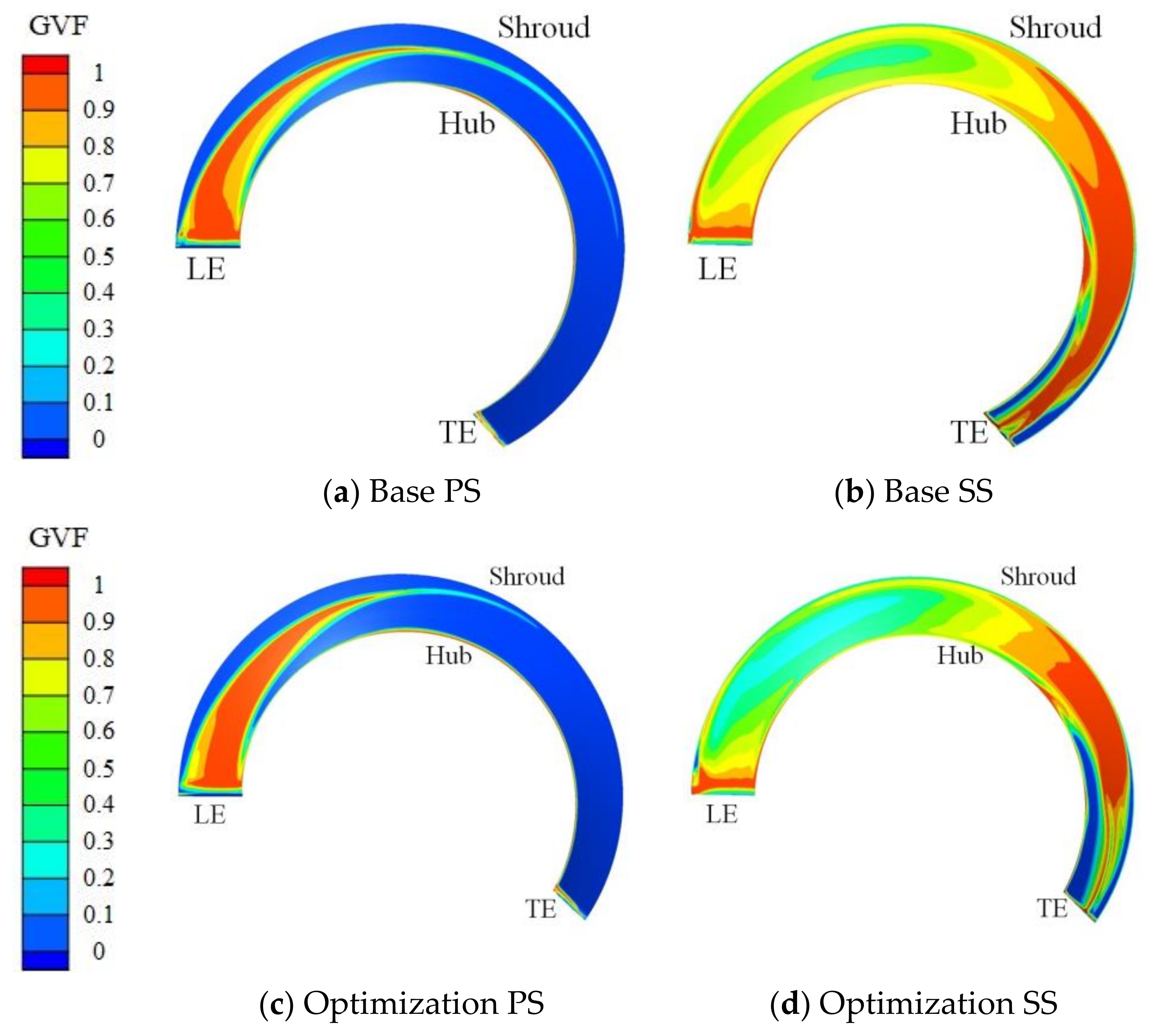
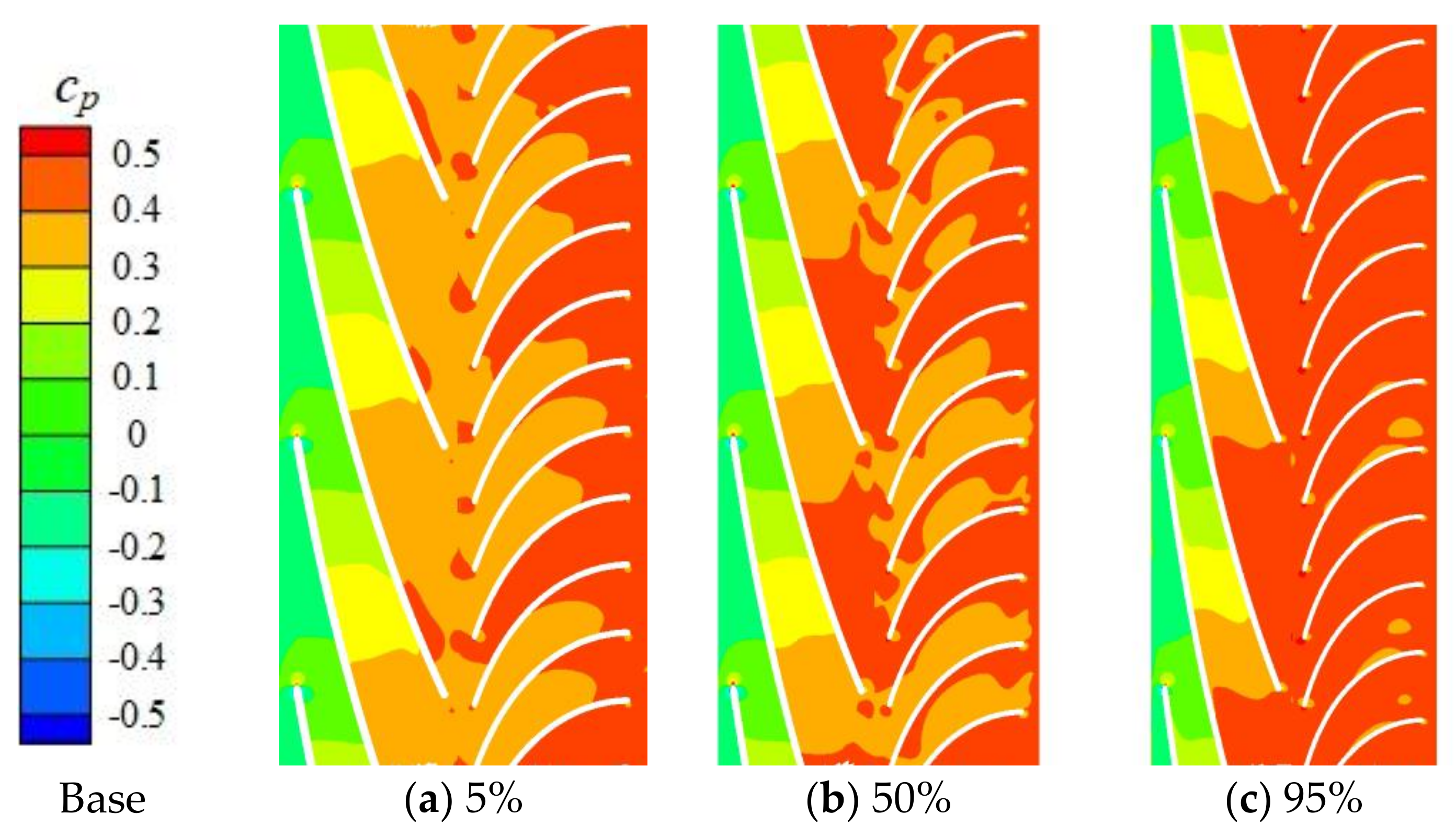
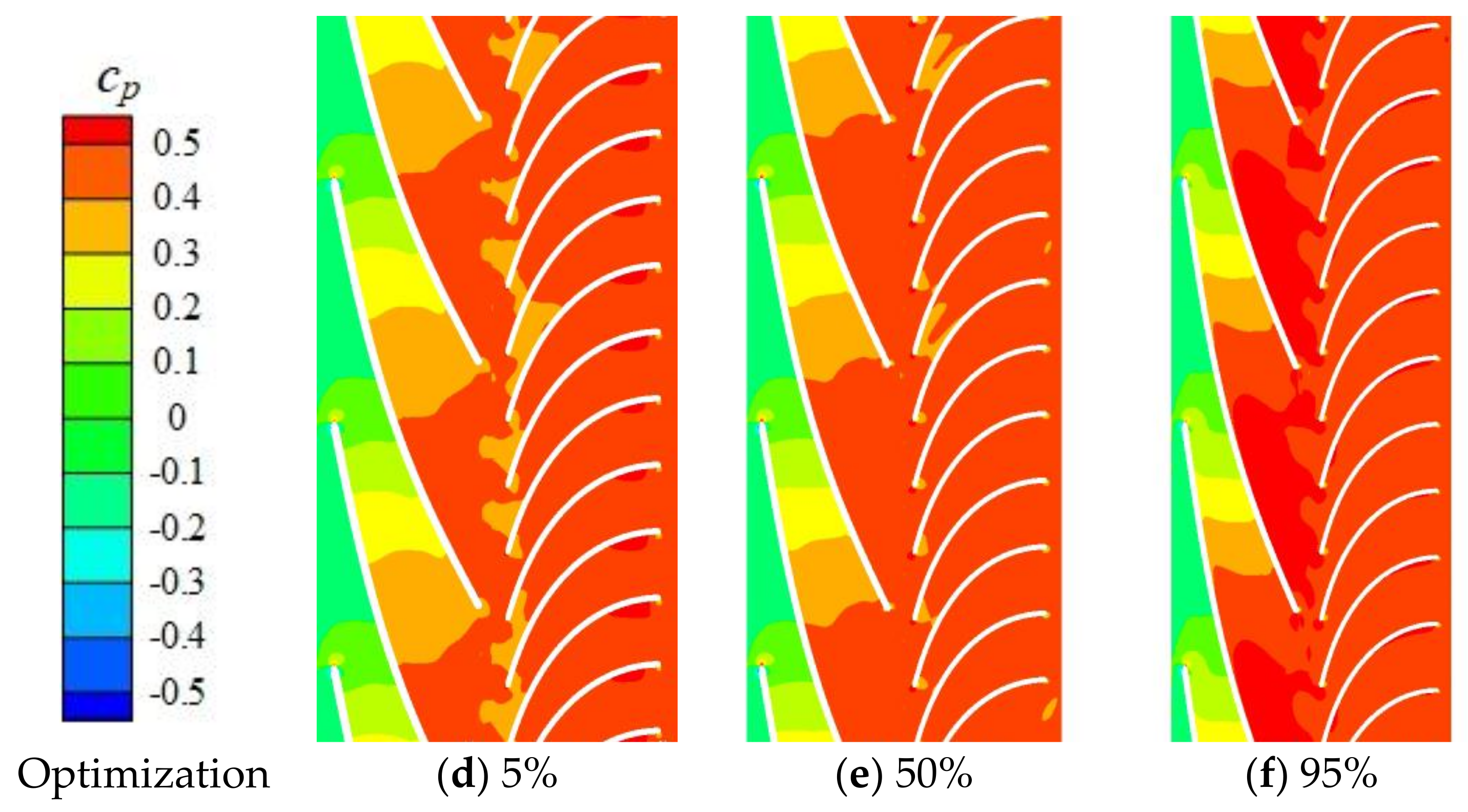
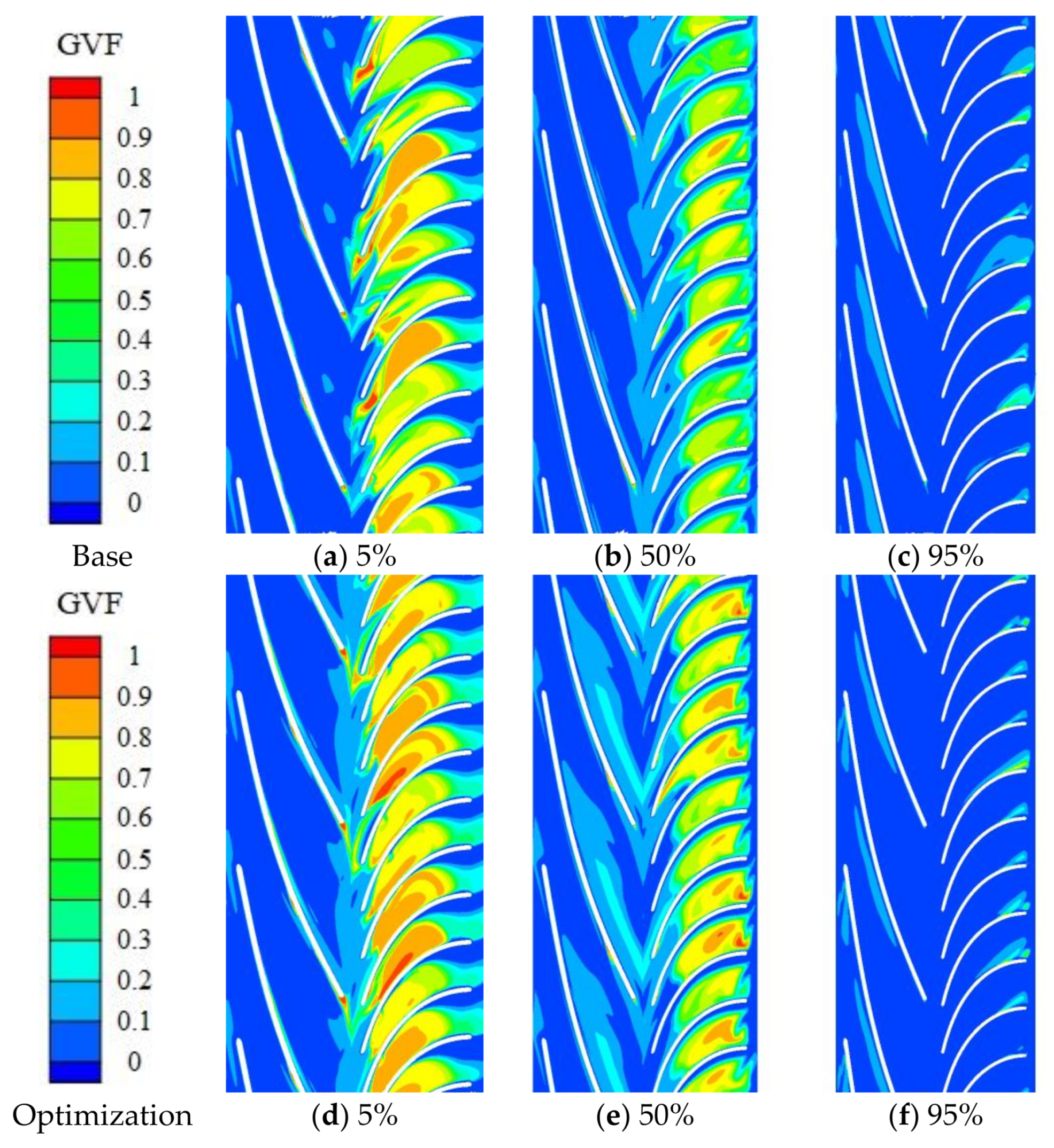
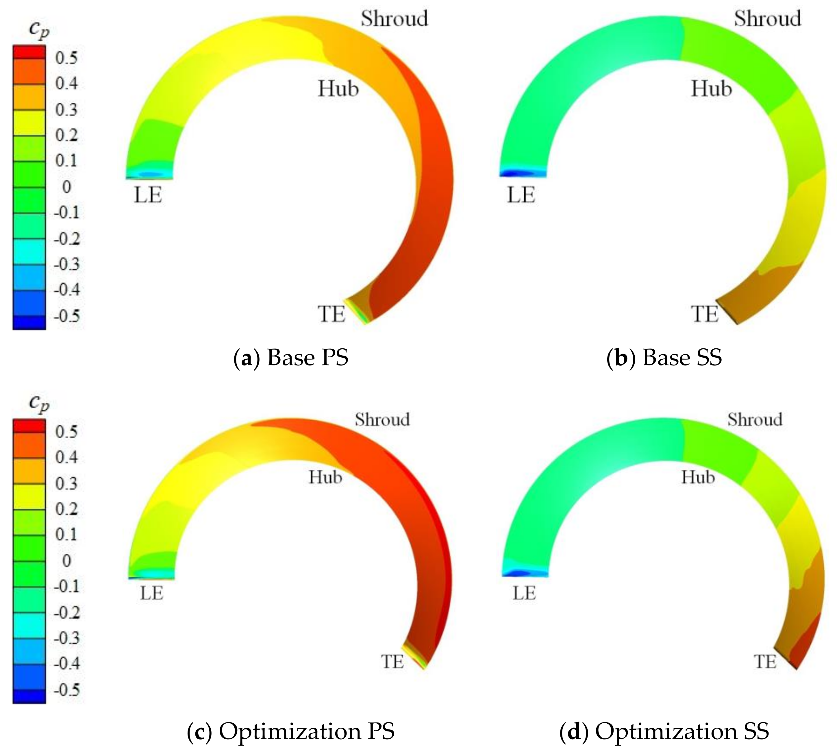
The distribution of gas volume fraction and the pressure inside multiphase pump of base mode and optimization pump is compared. It can be found that the distribution becomes more uniform after optimization, which improves the transporting performance of the optimization pump.

Acknowledgments

This work has been supported by the National Natural Science Foundation of China [51741906], the Open Research Fund Program of State key Laboratory of Hydroscience and Engineering [sklhse-2018-E-01], the State Key Laboratory of Hydroscience and Engineering [2018-KY-02], and the Key Laboratory of Fluid and Power Machinery (Xihua University), Ministry of Education [szjj-2017-100-1-004].

Author Contributions

Ming Liu, Lei Tan and Shuliang Cao proposed the design method; Ming Liu performed the simulations; Ming Liu and Lei Tan analyzed the data and wrote the paper.

Conflicts of Interest

The authors declare no conflict of interest.

References

  1. Dal Porto, D.F.; Larson, L.A. Multiphase-pump field trails demonstrate practical applications for the technology. SPE Prod. Facil. 1997, 12, 159–164. [Google Scholar] [CrossRef]
  2. Rabiger, K.; Maksoud, T.M.A.; Ward, J.; Hausmann, G. Theoretical and experimental analysis of a multiphase screw pump, handling gas-liquid mixtures with very high gas volume fractions. Exp. Therm. Fluid Sci. 2008, 32, 1694–1701. [Google Scholar] [CrossRef]
  3. Cao, S.L.; Peng, G.Y.; Yu, Z.Y. Hydrodynamics design of rotodynamics pump impeller for multiphase pumping by combined approach of inverse design and CFD analysis. J. Fluids Eng. 2005, 127, 330–338. [Google Scholar] [CrossRef]
  4. Zhang, J.Y.; Cai, S.J.; Zhu, H.W.; Zhang, Y.X. Experimental investigation of the flow at the entrance of a rotodynamic multiphase pump by visualization. J. Pet. Sci. Eng. 2015, 126, 254–261. [Google Scholar] [CrossRef]
  5. Zhang, J.Y.; Cai, S.J.; Li, Y.J.; Zhu, H.W.; Zhang, Y.X. Visualization study of gas-liquid two-phase flow patterns inside a three-stage rotodynamic multiphase pump. Exp. Therm. Fluid Sci. 2016, 70, 125–138. [Google Scholar] [CrossRef]
  6. Zhang, J.Y.; Li, Y.J.; Cai, S.J.; Zhu, H.W.; Zhang, Y.X. Investigation on the gas pockets in a rotodynamic multiphase pump. IOP Conf. Ser. Mater. Sci. Eng. 2016, 129, 012007. [Google Scholar] [CrossRef]
  7. Tan, L.; Zhu, B.S.; Cao, S.L.; Wang, Y.C.; Wang, B.B. Numerical simulation of unsteady cavitation flow in a centrifugal pump at off-design conditions. Proc. Inst. Mech. Eng. Part C J. Mech. Eng. Sci. 2014, 228, 1994–2006. [Google Scholar]
  8. Tan, L.; Zhu, B.S.; Wang, Y.C.; Cao, S.L.; Gui, S.B. Numerical study on characteristics of unsteady flow in a centrifugal pump volute at partial load condition. Eng. Comput. 2015, 32, 1549–1566. [Google Scholar] [CrossRef]
  9. Tan, L.; Yu, Z.Y.; Xu, Y.; Liu, Y.B.; Cao, S.L. Role of blade rotational angle on energy performance and pressure fluctuation of a mixed-flow pump. Proc. Inst. Mech. Eng. Part A J. Power Energy 2017, 231, 227–238. [Google Scholar]
  10. Yu, Z.Y.; Zhu, B.S.; Cao, S.L.; Wang, G.Y. Application of two-fluid model in the unsteady flow simulation for a multiphase rotodynamic pump. IOP Conf. Ser. Mater. Sci. Eng. 2013, 52, 062003. [Google Scholar] [CrossRef]
  11. Yu, Z.Y.; Zhu, B.S.; Cao, S.L.; Liu, Y. Effect of virtual mass force on the mixed transport process in a multiphase rotodynamic pump. Adv. Mech. Eng. 2014, 2, 958352. [Google Scholar] [CrossRef]
  12. Yu, Z.Y.; Zhu, B.S.; Cao, S.L. Interphase force analysis for air-water bubbly flow in a multiphase rotodynamic pump. Eng. Comput. 2015, 32, 2166–2180. [Google Scholar] [CrossRef]
  13. Zhang, J.Y.; Zhu, H.W.; Yang, C.; Li, Y.; Wei, H. Multi-objective shape optimization of helico-axial multiphase pump impeller based NSGA-II and ANN. Energy Convers. Manag. 2011, 52, 538–546. [Google Scholar] [CrossRef]
  14. Hu, H.; Li, X.K.; Gu, B. Hydraulic optimization of multiphase pump based on CFD and genetic algorithm. International J. Grid Distrib. Comput. 2015, 8, 161–170. [Google Scholar]
  15. Zhang, J.Y.; Cai, S.J.; Li, Y.J.; Zhou, X.; Zhang, Y.X. Optimization design of multiphase pump impeller based on combined genetic algorithm and boundary vortex flux diagnosis. J. Hydrodyn. 2017, 29, 1023–1034. [Google Scholar] [CrossRef]
  16. Kim, J.H.; Lee, H.C.; Kim, J.H.; Choi, Y.S.; Yoon, J.Y.; Yoo, I.S.; Choi, W.C. Improvement of hydrodynamic performance if a multiphase pump using design of experiment techniques. J. Fluid Eng. 2015, 137, 081301. [Google Scholar] [CrossRef]
  17. Suh, J.W.; Kim, J.H.; Choi, Y.S.; Joo, W.G.; Lee, K.Y. A study on numerical optimization and performance verification of multiphase pump for offshore plant. Proc. Inst. Mech. Eng. Part A J. Power Energy 2017, 231, 382–397. [Google Scholar] [CrossRef]
  18. Suh, J.W.; Kim, J.W.; Choi, Y.S.; Kim, J.H.; Joo, W.G.; Lee, K.Y. Multi-objective optimization of the hydrodynamic performance of the second stage of a multi-phase pump. Energies 2017, 10, 1334. [Google Scholar] [CrossRef]
  19. Byrne, D.M.; Taguchi, S. The Taguchi approach to parameter design. Qual. Prog. 1987, 20, 19–26. [Google Scholar]
  20. Shi, W.D.; Wang, C.; Lu, W.G.; Zhou, L.; Zhang, L. Optimization design of stainless steel stamping multistage pump based on orthogonal test. Int. J. Fluid Mach. Syst. 2010, 3, 309–314. [Google Scholar]
  21. Zhou, L.; Shi, W.D.; Lu, W.G. Orthogonal test design and numerical simulation of 100QJ10 Type deep-well pump. Appl. Mech. Mater. 2012, 110, 2590–2595. [Google Scholar] [CrossRef]
  22. Zhou, L.; Shi, W.D.; Wu, S.Q. Performance optimization in a centrifugal pump impeller by orthogonal experiment and numerical simulation. Adv. Mech. Eng. 2013, 5, 385809. [Google Scholar] [CrossRef]
  23. Zhao, B.J.; Hou, D.H.; Chen, H.L.; Wang, Y.; Qiu, J. Optimization design of a double-channel pump by means of orthogonal test, CFD, and experimental analysis. Adv. Mech. Eng. 2014, 6, 545216. [Google Scholar] [CrossRef]
  24. Xu, Y.; Tan, L.; Cao, S.L.; Qu, W.S. Multiparameter and multiobjective optimization design of centrifugal pump based on orthogonal method. Proc. Inst. Mech. Eng. Part C J. Mech. Eng. Sci. 2017, 231, 2569–2579. [Google Scholar] [CrossRef]
  25. Zhang, Y.X.; Zhang, J.Y.; Zhu, H.W.; Cai, S.J. 3D blade hydraulic design method of the rotodynmic multiphase pump impeller and performance research. Adv. Mech. Eng. 2014, 6, 803972. [Google Scholar] [CrossRef]
  26. Tan, L.; Cao, S.L.; Gui, S.B. Hydraulic design and pre-whirl regulation law of inlet guide vane for centrifugal pump. Sci. China Technol. Sci. 2010, 53, 2142–2151. [Google Scholar] [CrossRef]
  27. Menter, F.R. Two-Equation Eddy-Viscosity Turbulence Models for Engineering Applications. AIAA J. 1994, 32, 1598–1605. [Google Scholar] [CrossRef]
  28. ANSYS Inc. ANSYS14.5 Help, CFX, Theory Guide; ANSYS Inc.: Canonsburg, PA, USA, 2014. [Google Scholar]
  29. Clift, R.; Grace, J.R.; Weber, M.E. Bubbles, Drops and Particles; Academic Press: New York, NY, USA, 1978. [Google Scholar]
  30. Sato, Y.; Sekoguchi, K. Liquid velocity distribution in two-phase bubble flow. Int. J. Multiph. Flow 1973, 2, 79–85. [Google Scholar] [CrossRef]
  31. Hao, Y.; Tan, L.; Liu, Y.B.; Xu, Y.; Zhang, J.S.; Zhu, B.S. Energy performance and radial force of a mixed-flow pump with symmetrical and unsymmetrical tip clearances. Energies 2017, 10, 57. [Google Scholar] [CrossRef]
  32. Liu, Y.B.; Tan, L.; Hao, Y.; Xu, Y. Energy performance and flow patterns of a mixed-flow pump with different tip clearance sizes. Energies 2017, 10, 191. [Google Scholar] [CrossRef]
  33. Tan, L.; Xie, Z.F.; Liu, Y.B.; Hao, Y.; Xu, Y. Influence of T-shape tip clearance on performance of a mixed-flow pump. Proc. Inst. Mech. Eng. Part A J. Power Energy 2017. [Google Scholar] [CrossRef]
Figure 1. Schematic diagram of meridional plane.
Energies 11 01048 g001
Figure 2. Velocity triangles at impeller outlet and diffuser inlet.
Energies 11 01048 g002
Figure 3. Meridional plane of the base pump [16].
Energies 11 01048 g003
Figure 4. Computational domain.
Energies 11 01048 g004
Figure 5. Mesh distribution.
Energies 11 01048 g005
Figure 6. Comparison of pump performance between experimental and numerical results.
Energies 11 01048 g006
Figure 7. Distribution of blade angle along relative meridional streamline.
Energies 11 01048 g007aEnergies 11 01048 g007b
Figure 8. Three-dimensional structure of base pump and optimization pump.
Energies 11 01048 g008
Figure 9. Comparison of gas volume fraction between base and optimization pumps.
Energies 11 01048 g009
Figure 10. Distribution of gas volume fraction on blade surface.
Energies 11 01048 g010
Figure 11. Comparison of pressure between base and optimization pumps.
Energies 11 01048 g011aEnergies 11 01048 g011b
Figure 12. Distribution of pressure coefficient on blade surface.
Energies 11 01048 g012
Figure 13. Distribution of axial velocity and streamline in diffuser.
Energies 11 01048 g013
Table 1. Parameters for the rotodynamic multiphase pump.
ItemValue
Rotational speed3600 rpm
Pressure rise (GVF = 0%)230 kPa
Rated flow rate100 m3/h
Table 2. Independence test of mesh number.
ItemMesh 1Mesh 2Mesh 3Mesh 4
Inlet pipe443,916443,916443,916443,916
Impeller1,711,0052,324,4122,829,2523,442,440
Diffuser790,0201,079,8041,337,6881,613,898
Outlet pipe907,236907,236907,236907,236
Total3,852,1774,755,3685,518,0926,407,490
GVF = 0Pressure rise (kPa)198.8196.8197.0196.2
Efficiency (%)62.6362.0562.0161.72
GVF = 10%Pressure rise (kPa)178.8178.8178.2178.8
Efficiency (%)58.3258.3758.1558.32
Table 3. Orthogonal factors and levels.
LevelFactor
βIs0βI0βIs1khks
16.52200.450.45
272.5210.50.5
37.53220.550.55
483.5230.60.6
Table 4. Orthogonal table.
Individual No.Factor
βIs0βI0βIs1khks
16.52200.450.45
26.52.5210.550.6
36.53220.60.5
46.53.5230.50.55
572210.50.5
672.5200.60.55
773230.550.45
873.5220.450.6
97.52220.550.55
107.52.5230.450.5
117.53200.50.6
127.53.5210.60.45
1382230.60.6
1482.5220.50.45
1583210.450.55
1683.5200.550.5
Table 5. Multiphase pump performance.
Individual No.Pressure Rise ∆p (kPa)
1130.73
2163.41
3155.58
4162.96
5153.71
6164.41
7162.73
8171.41
9174.80
10159.59
11178.22
12169.28
13188.09
14172.00
15179.53
16176.35
Table 6. Orthogonal analysis for pressure rise.
βIs0βI0βIs1khks
k ¯ 1 153.17161.83162.43160.31158.68
k ¯ 2 163.06164.85166.48169.32175.28
k ¯ 3 170.47169.01168.44169.34161.31
k ¯ 4 178.99170.00168.34166.72170.42
R25.828.176.029.0316.59

