A Method for Distributed Control of Reactive Power and Voltage in a Power Grid: A Game-Theoretic Approach

Abstract
:1. Introduction
2. Game Theory Overview
2.1. Terminologies
- Nash equilibrium: this captures a steady state of play of a game in which each player holds the correct expectation about the other player’s behavior and acts rationally [15]. It states that all players are, individually, playing their best responses to the actions of others [14]. There is no incentive for any player to deviate.
- Subgame: given perfect information, extensive-form game G, the subgame of G at node h is the restriction of G to the descendants of h [14]. The subgame is a part of the overall extensive game tree, with the overall game tree being the largest subgame. Leyton-Brown and Shoham [14] state requirements to be satisfied for a game to be called a subgame.
- Backward induction: this is an important solution concept utilized in solving extensive form games. By determining the equilibrium play of a lower subgame, further analysis can be carried out until one arrives at the top or root of the tree. According to Shoham and Leyton, it is based on the assumption that that subgame equilibrium will be played as one backs up the tree. This concept is used to arrive at a final solution.
- Subgame perfect equilibrium: these are all strategy profiles, S, such that for any subgame G’ of G, the restriction of S to G’ is a Nash equilibrium of G’ [14]. The direct implication of this is that at every point in history, a player’s strategy is always optimal. Hence, for every strategy profile in history, a state of Nash equilibrium is always achieved. This notion eliminates several Nash equilibria wherein players’ threats are not credible [15].
2.2. Mathematical Representations
- Normal form game: a finite, n-person game is a tuple defined as:N = Set of n number of players, indexed by i.A = A1 × …An, Ai set of actions available to player i.U = (U1…Un), Ui: A→R is a real-valued quantity (or payoff function) for player i.
- Extensive form game: a perfect-information game is defined as:H = set of non-terminal choice nodes. (A choice node is that stage of a game where a player makes a strategic decision on available options).Z = set of terminal nodes, disjoint from H.H→2A is the action function, which assigns to each choice node a set of possible actions.H→N is the player function, which assigns to each non-terminal node player i who chooses an action at that node.H × A→H ∪ Z is the successor function mapping a choice node and an action to a new choice node or terminal node.
3. Reactive Power Contributions of Power System Components
3.1. Generator
- = reactive power injection into generator bus gk;
- N = number of buses;
- , = voltages at buses gk and n;
- = admittance matrix entry between buses gk and n;
- = phase angle of the admittance matrix entry between buses gk and n; and
- , = phase angles at buses n and gk.
3.2. Tap-Changing Transformer
3.3. Shunt Reactive Compensator
4. Centralized Game Model
4.1. Objectives
4.2. Players
4.3. Actions
4.4. Payoffs
4.5. Payoff Vector
4.6. Power-Flow Equations
4.7. Constraints
- Equality constraints: this defines the amount of power being injected into a bus [11]:where and are the real and reactive powers injected into bus k, respectively; and are the real and reactive powers absorbed by the load connected at bus k, respectively; and and are the real and reactive powers injected into the line at bus k, respectively.
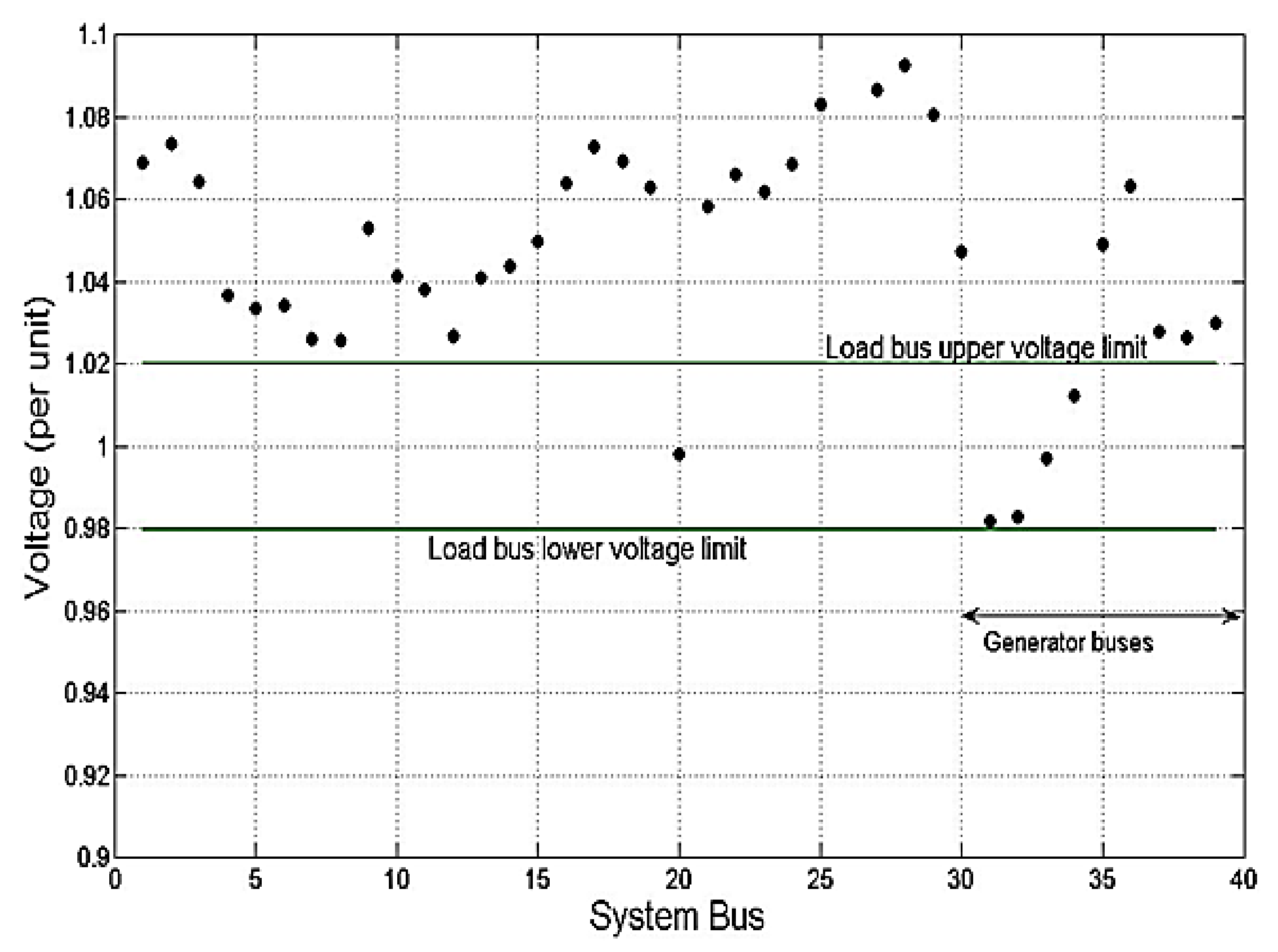
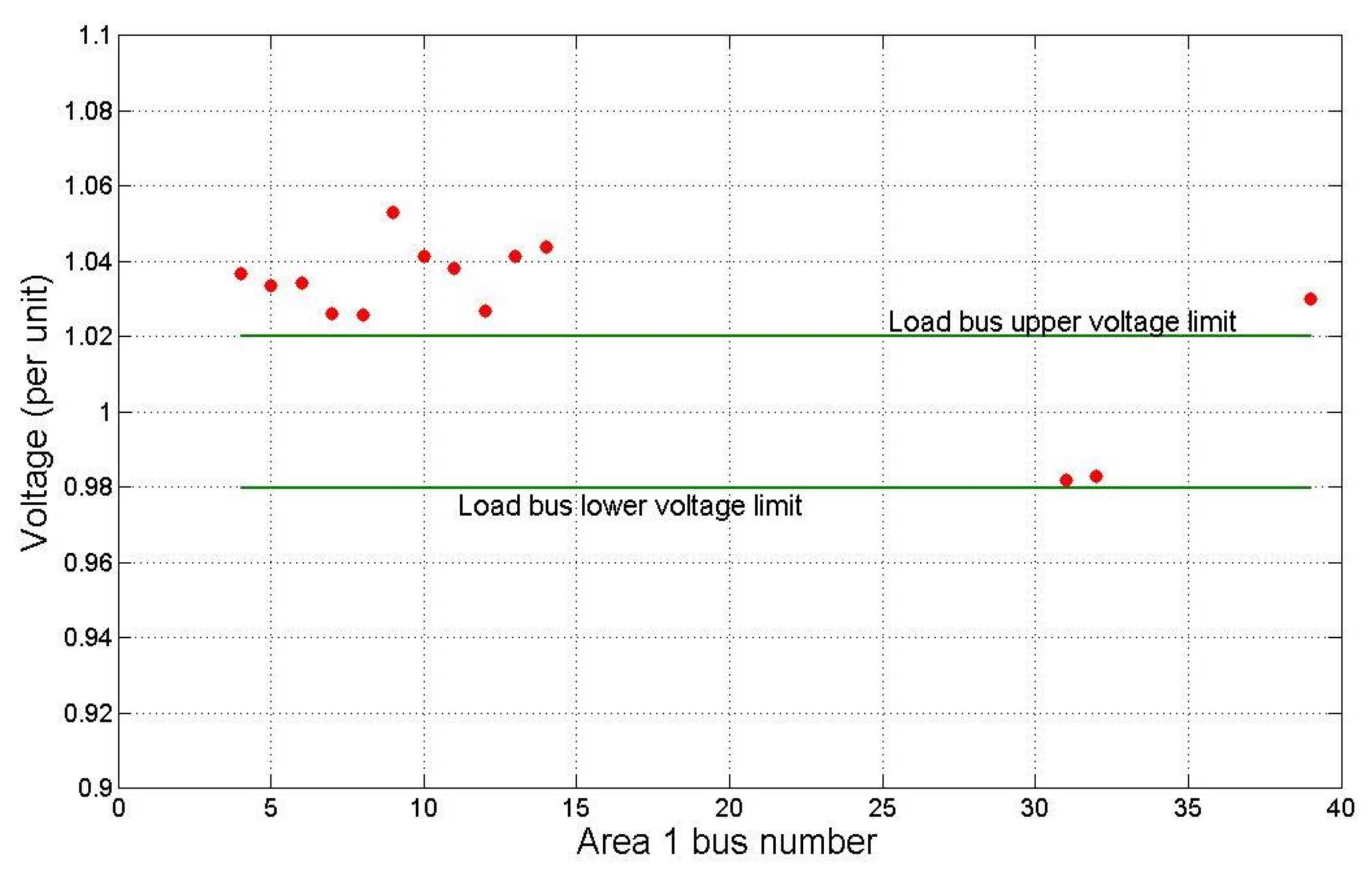
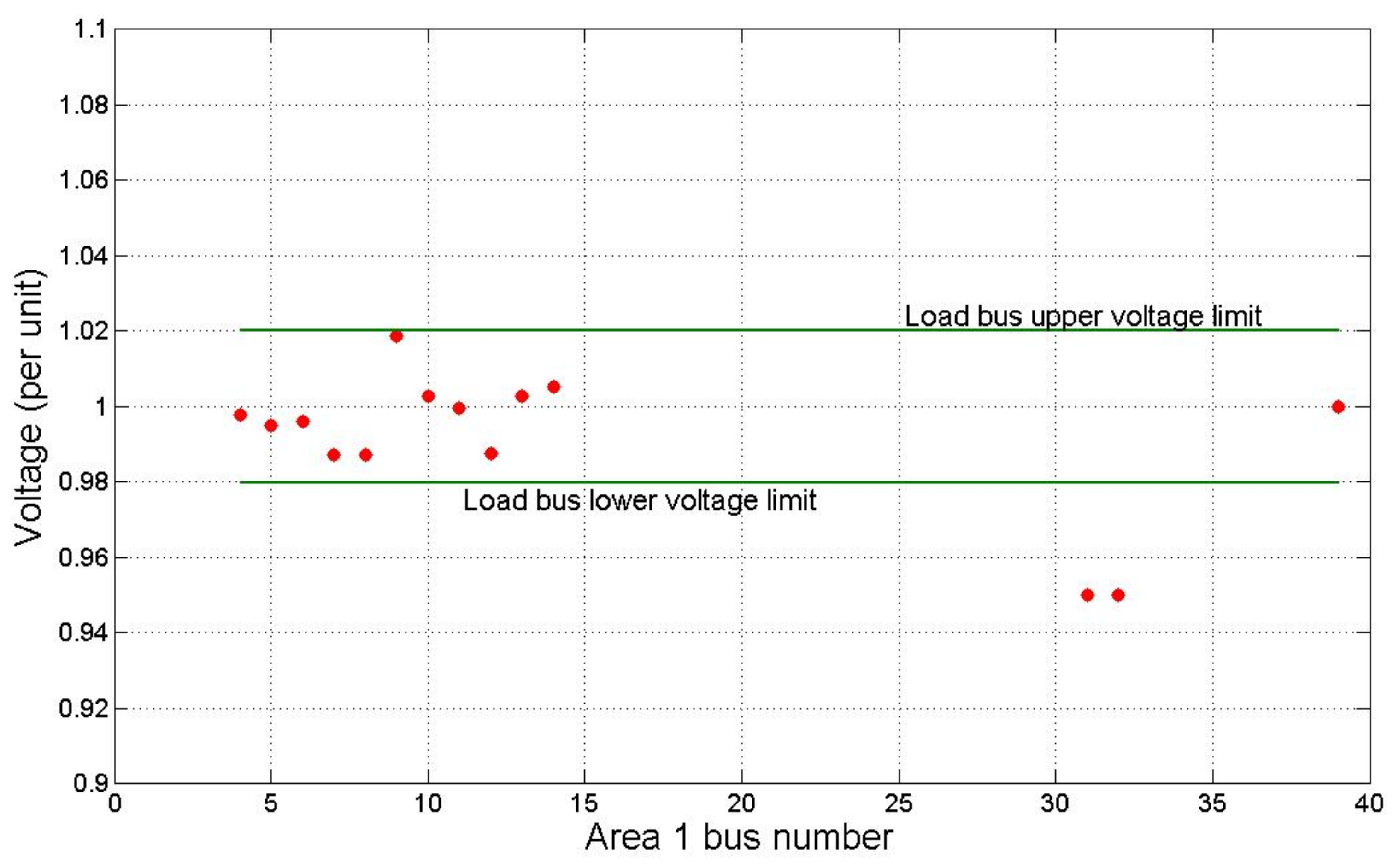
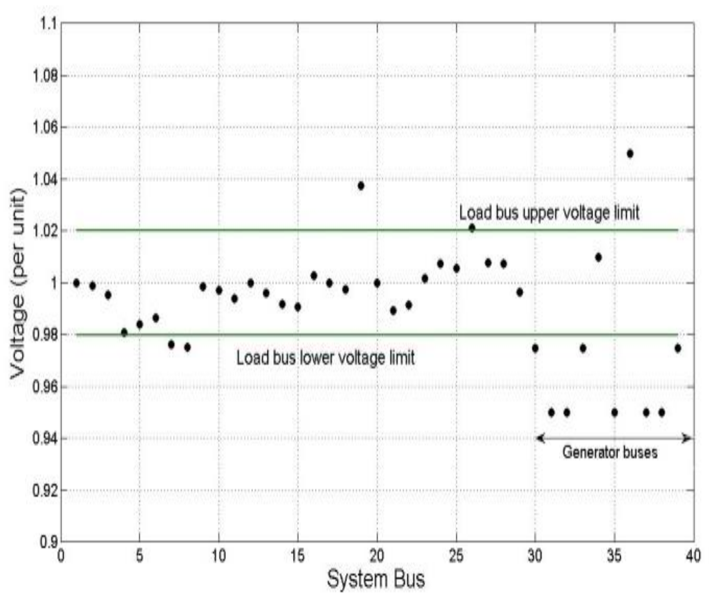
- Inequality constraints: these define the lower and upper limits of operation of the components and system specifications [11]:where is the generator reactive power input; is the AVR setting of the generator; is the transformer tap setting; is the value of the shunt reactive power compensator; and is the voltage at the load buses. These values are all defined within their operating lower and upper limits.
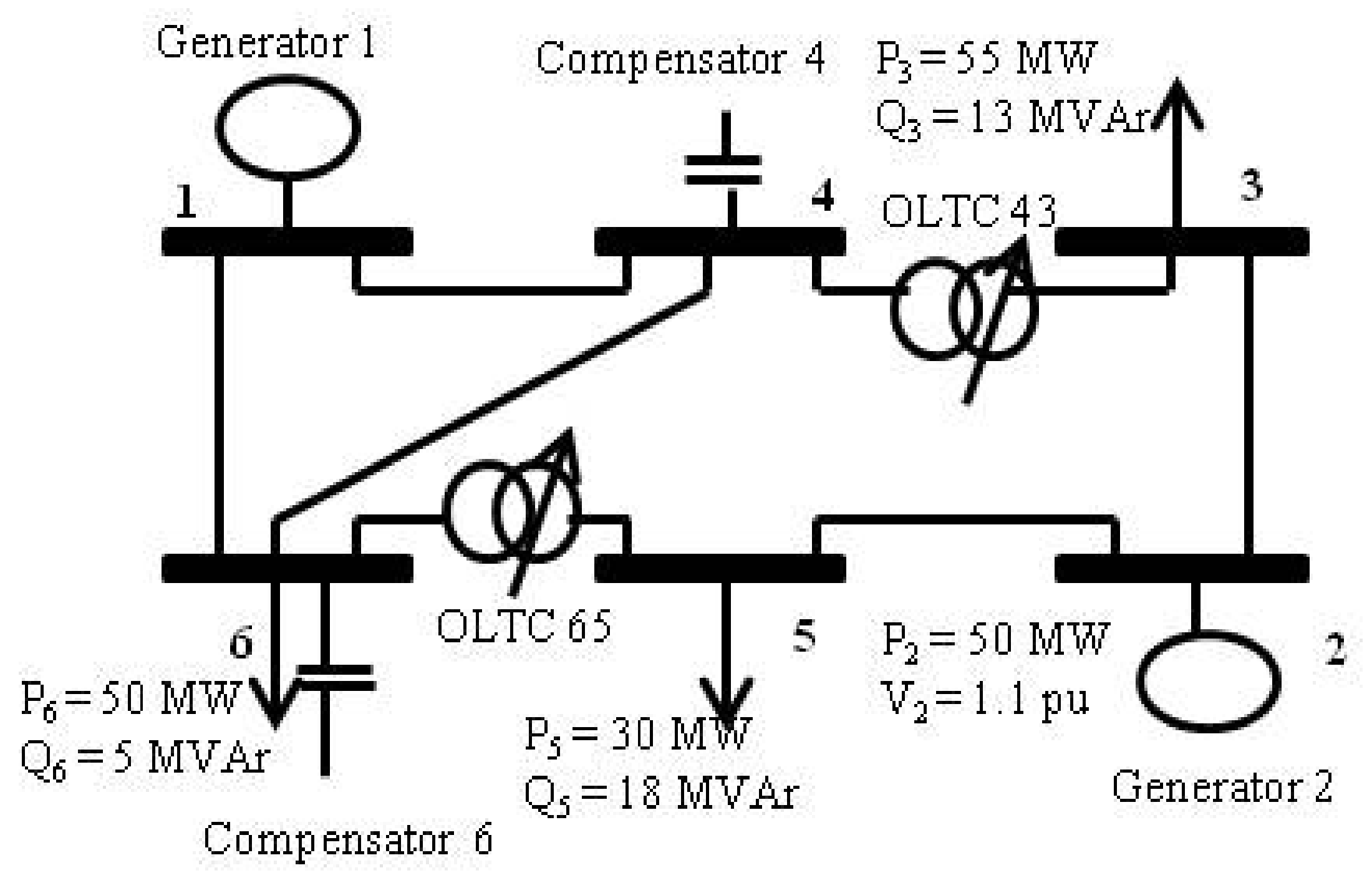
4.8. Power-System Model
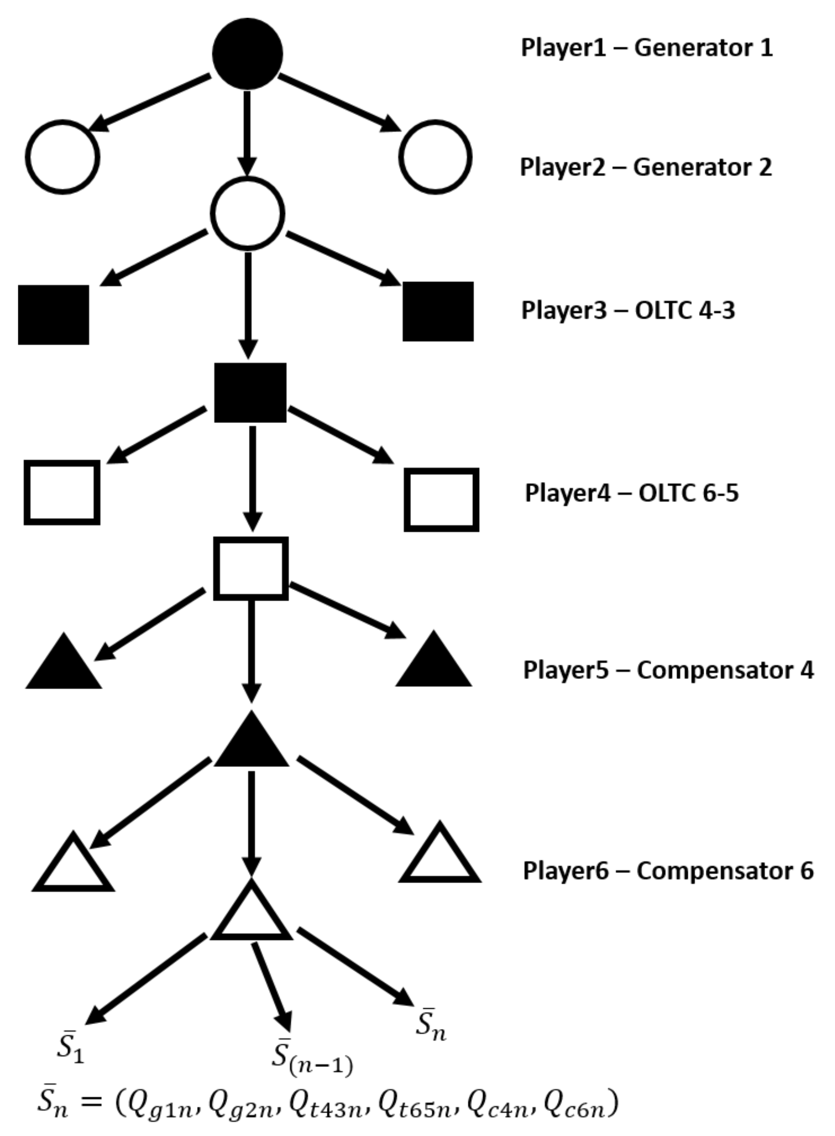
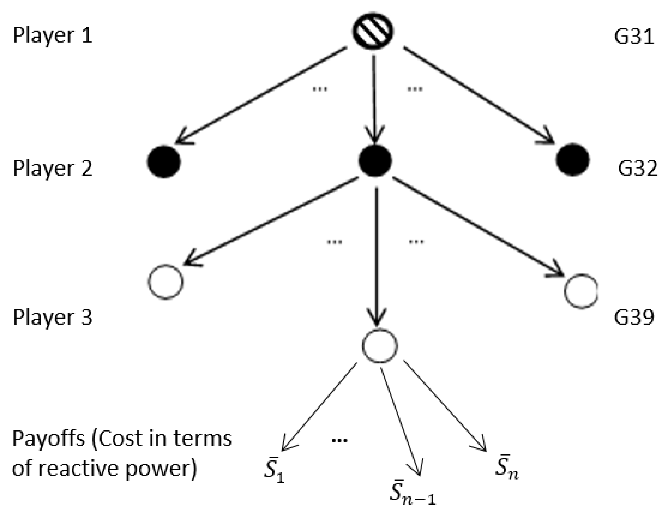
4.9. Centralized Game-Theoretic Model
4.10. Power Components’ Payoffs
- : nth possible reactive power injections by generators 1 and 2.
- : nth possible reactive power flowing along OLTC branches connected to terminal buses 4 (6) and 3 (5).
- : nth possible reactive power injections by compensators at buses 4 and 6.
5. Game-Theoretic Equations and Algorithms
5.1. Formulated Game-Theoretic Equation
5.2. Formulated Game-Theoretic Algorithm
- (1)
- Data preparation: this stage was carried out prior to actual game play. After the determination of all the possible strategy profiles, the load voltage constraint was applied to filter out strategy profiles that did not satisfy the load voltage tolerance definition. This ensured that only valid profiles remained for game play activity. The data preparation process used to extract only the feasible profiles is shown in Algorithm 1.
- (2)
- Game play: this is the actual execution of backward induction beginning from the terminal node of the game tree. This stage is carried out after the data preparation stage, and this game play process is shown in Algorithm 2. By implementing steps (13)–(16), only profiles at every player node that ensure least reactive power contribution by that player are selected.
| Algorithm 1 Prior data preparation |
| Input:N-players ( with number of actions respectively; Define equality, inequality and load voltage constraints (10)–(11); Define load bus voltages i.e., ; Output: Vectors of load bus voltages and reactive power contributions |
| Invalidate combination settings with unacceptable voltages 1. For (Total combinations—) 2. Run power flow program; 3. Prune: If all load bus voltages satisfy voltage limits in (11) 4. Save: i, , component settings 5. Extract terminal nodes, Z←Reactive power payoff vectors 6. else Discard: i, , component settings 7. Proceed to i + 1 8. End |
| Algorithm 2 Reactive power game control (RPGC) |
| Input Vectors of load bus voltages and reactive power contributions Define mini = 9999 (Arbitrary large value) Output: Optimal component settings |
| # of players, N; Let players[P1,P2,P3,P4,P5,…PN] have [a,b,c,…]] possible actions For1:N do Fori = 1:a do 4: if Z←P1 then Goto (20) end if Forj = 1:b do if Z←P2 then Goto (20) 8: end if Fork = 1:c do if Z←P3 then Goto (20) end if 12: For l … … … if Z←P6 then 20: if reactive power cost ≤ mini then mini←reactive power cost SGE{ijklmn}←mini Assign SGE{ijklmn} as newly extracted terminal nodes, Z←P(N-1) 24: end if end if end for … … … End For Repeat algorithm until the root of the tree at player P1 is reached. SGE: Sub-game equilibrium |
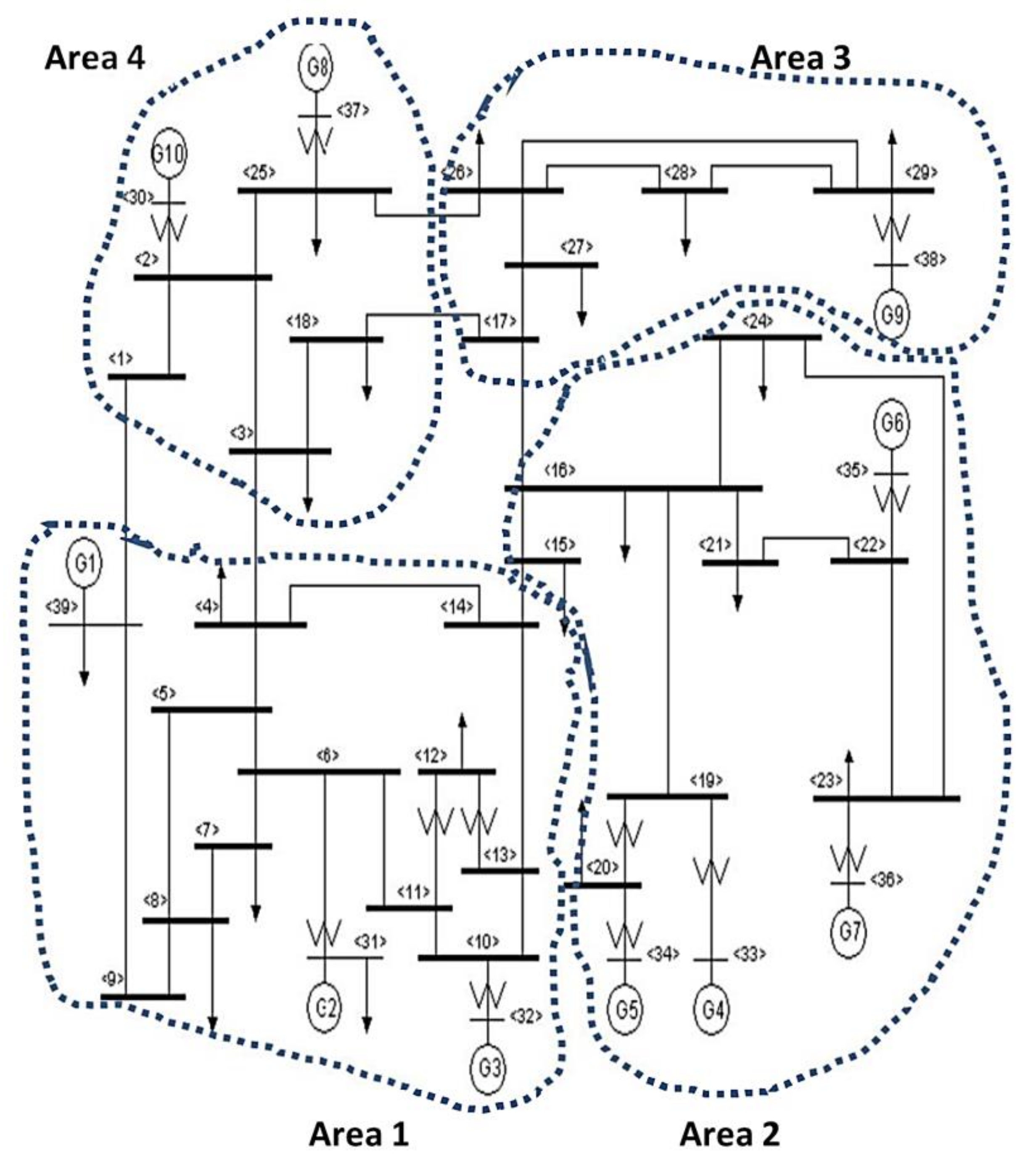
6. Distributed Game Model
6.1. Power System Model
6.2. Decoupling
- (1)
- Decoupling of the system into independent control areas.
- (2)
- Application of the GT algorithm to systematically control reactive power and voltage in each area. This will result in optimal control settings of the power system components in each control area.
- (3)
- A system convergence test using the optimal settings derived from step 2.
6.3. Distributed Game-Theoretic Model
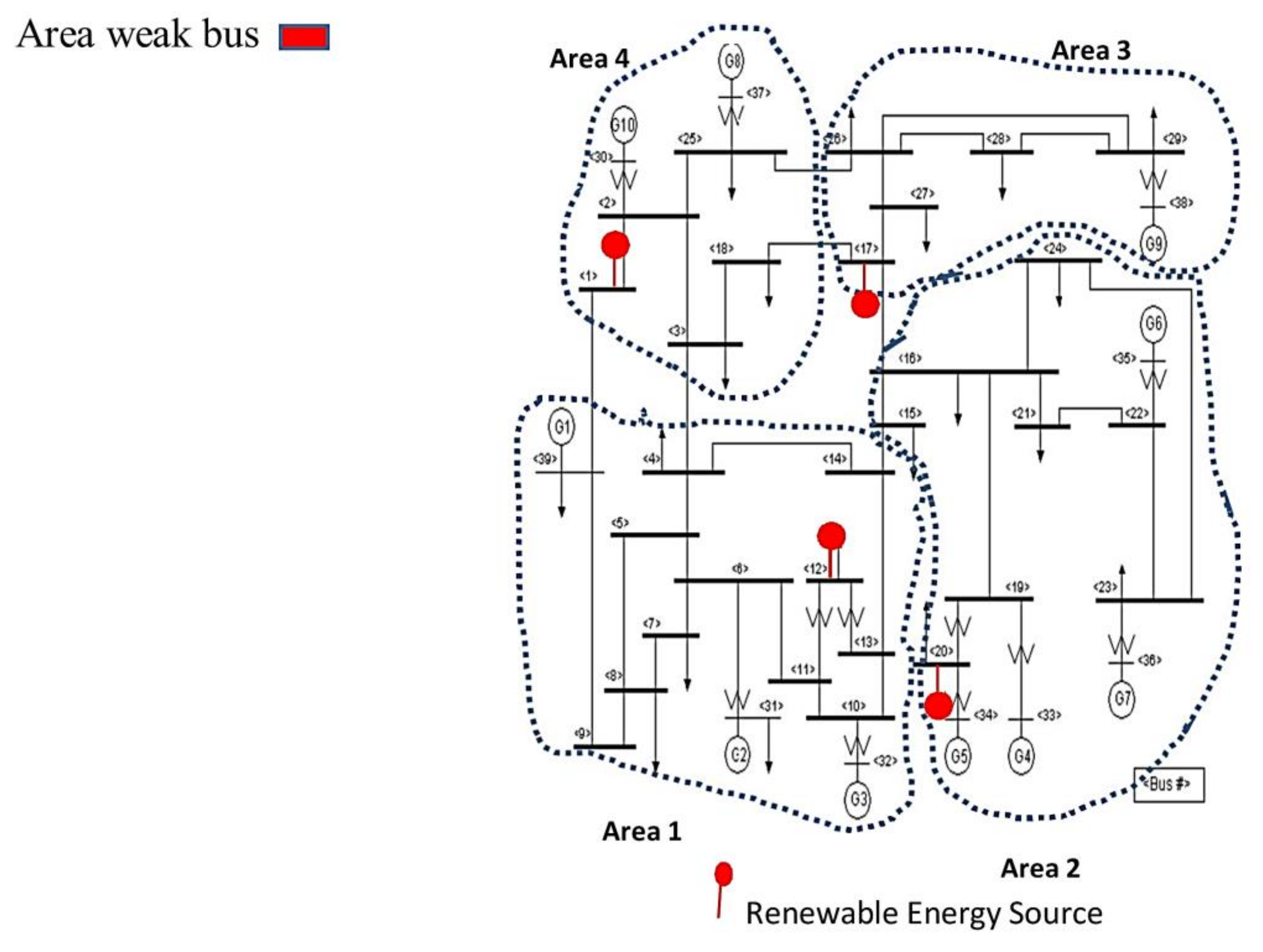
7. Integration of Distributed, Renewable Energy Sources
7.1. Voltage-Reactive Power (V-Q) Sensitivity
7.2. Game-Theoretic Formulation and Approach
| Algorithm 3 Renewable energy integration at weak buses (REIWB) |
| @ each control area, 1: Solve power flow equations to obtain initial, at all buses 2: RPVS matrix, L is computed from with emphasis on the diagonal elements, To determine all entiries: Initialize empty array of RPVS_Diag_Entries For i = 1: Number of load buses For r = 1: Number of buses Initialize x = 0; If r = i, Sin else Sin() end end Update entries in RPVS_Diag_Entries end 3: Find weakest bus from min(RPVS_Diag_Entries) 4: Place renewable energy (acting as reactive power source) at PV bus to maintain voltage at 1.0 p.u. 5: Execute game algorithm to obtain optimal generator settings. 6: Solve power flow with optimal settings. 7: Determine reactive power injection by renewable energy source. Extract injected reactive power from renewable source in each area and update in overall system data. 8: Solve overall system power flow for new voltage profile; renewable energy buses are now PQ-buses. |
8. Simulation Results
9. Conclusions
Acknowledgments
Author Contributions
Conflicts of Interest
Nomenclature
| nth possible reactive power injection by generator or compensator component labeled | |
| nth possible reactive power flow along transformer branch and | |
| Voltage at generator bus | |
| Reactive power injection at generator bus | |
| Voltage at bus | |
| Complex power flowing from bus to | |
| Bus admittance entry between buses and | |
| Transformer branch reactive power from to | |
| Transformer tap settings between buses and | |
| nth payoff vector comprising reactive power contributions for all players for any | |
| For any subgame and ith player assignment, the set of all payoffs located at the leaf or terminal nodes |
References
- Phulpin, Y.; Begovic, M.; Ernst, D. Coordination of voltage control in a power system operated by multiple transmission utilities. In Proceedings of the 2010 IREP Symposium Bulk Power System Dynamics and Control—VIII (IREP), Rio de Janeiro, Brazil, 1–6 August 2010; pp. 1–8. [Google Scholar]
- Zhang, A.; Li, H.; Liu, F.; Yang, H. A coordinated voltage/reactive power control method for multi-TSO power systems. Int. J. Electr. Power Energy Syst. 2012, 43, 20–28. [Google Scholar] [CrossRef]
- Zima, M.; Ernst, D. On multi-area control in electric power systems. In Proceedings of the 15th Power System Computation Conference (PSCC), Liège, Belgium, 22–26 August 2005; pp. 22–26. [Google Scholar]
- Mousavi, O.A.; Cherkaoui, R. On the inter-area optimal voltage and reactive power control. Int. J. Electr. Power Energy Syst. 2013, 52, 1–13. [Google Scholar] [CrossRef]
- Dong, F.; Howdhury, B.H.; Crow, M.L.; Acar, L. Power Reserve Management. IEEE Trans. Power Syst. 2005, 20, 338–345. [Google Scholar] [CrossRef]
- Kundur, P. Power Systems Stability and Control; Mc-Graw Hill: New York, NY, USA, 1994; pp. 967–996. [Google Scholar]
- Schlueter, R.A. A voltage stability security assessment method. IEEE Trans. Power Syst. 1998, 13, 1423–1438. [Google Scholar] [CrossRef]
- Pradeep, H.; Venugopalan, N. A study of voltage collapse detection for power systems. Int. J. Emerg. Technol. Adv. Eng. 2013, 3, 325–331. [Google Scholar]
- Mantawy, A.H.; Al-Ghamdi, M.S. A new reactive power optimization algorithm. In Proceedings of the 2003 IEEE Bologna Power Tech Conference Proceedings, Bologna, Italy, 23–26 June 2003; pp. 470–475. [Google Scholar]
- Sharma, N.K.; Babu, D.S. Application of particle swarm optimization technique for reactive power optimization. In Proceedings of the IEEE-International Conference on Advances in Engineering, Science And Management (ICAESM-2012), Tamil Nadu, India, 30–31 March 2012; pp. 88–93. [Google Scholar]
- Vlachogiannis, J.G.; Lee, K.Y. A comparative study on particle swarm optimization for optimal steady-state performance of power systems. IEEE Trans. Power Syst. 2006, 21, 1718–1728. [Google Scholar] [CrossRef]
- Bakare, G.A.; Venayagamoorthy, G.K.; Member, S.; Aliyu, U.O. Reactive power and voltage control of the Nigerian grid system using micro-genetic algorithm. Power Eng. Soc. Meet. 2005, 2, 1916–1922. [Google Scholar]
- Yoshida, H.; Kawata, K. A particle swarm optimization for reactive power and voltage control. IEEE Trans. Power Syst. 2001, 15, 1232–1239. [Google Scholar] [CrossRef]
- Leyton-Brown, K.; Shoham, Y. Essentials of Game Theory: A Concise Multidisciplinary Introduction; Morgan and Claypool: San Rafael, CA, USA, 2008; pp. 3–40. [Google Scholar]
- Osborne, M.J.; Rubinstein, A. A Course in Game Theory; MIT Press: Cambridge, UK, 2011; pp. 1–19. [Google Scholar]
- Rasmusen, E. Games and Information: An Introduction to Game Theory, 3rd ed.; Blackwell: Oxford, UK, 2001; pp. 15–60. [Google Scholar]
- Holler, M.J. Classical, Modern and New Game Theory; Hamburg, Germany, 2001. Available online: https://law.yale.edu/system/files/documents/pdf/holler.pdf (accessed on 18 July 2014).
- Kuhn, H.W.; Harsanyu, J.C.; Selten, R.; Weibull, J.W.; van Damme, E.; Nash, J.F., Jr.; Hammerstein, P. The work of John F. Nash Jr. in game theory: Nobel Seminar. Duke Math. J. 1995, 81, 1–29. [Google Scholar] [CrossRef]
- Momoh, J.A. Electric Power System Applications of Optimization; CRC Press: Boca Raton, FL, USA, 2000. [Google Scholar]
- Idehen, I.; Abraham, S.; Murphy, G.V. Reactive power and voltage control in a power grid: A game-theoretic approach. In Proceedings of the 2018 IEEE Texas Power and Energy Conference (TPEC), College Station, TX, USA, 8–9 February 2018; pp. 1–6. [Google Scholar]
- The IEEE 10 Generator 39 Bus System. Available online: http://sys.elec.kitami-it.ac.jp/ueda/demo/WebPF/39-New-England (accessed on 11 January 2014).
- Granada, M.; Rider, M.J.; Mantovani, J.R.S.; Shahidehpour, M. A decentralized approach for optimal reactive power dispatch using a Lagrangian decomposition method. Electr. Power Syst. Res. 2012, 89, 148–156. [Google Scholar] [CrossRef]
- Idehen, I. A Method for Distributed Control of Reactive POWER and Voltage in a Power Grid: A Game-Theoretic Approach. Master’s Thesis, Tuskegee University, Tuskegee, Alabama, 2014, unpublished. [Google Scholar]
- Samad, T.; Annaswamy, A.M. Control for Renewable Energy and Smart Grids. Impact of Control Technology. 2011. Available online: www.ieeecss.org (accessed on 18 July 2014).
- Chowdhury, B.H.; Taylor, C.W. Voltage Stability Analysis: V-Q Power Flow Simulation Versus Dynamic Simulation. IEEE Trans. Power Syst. 2000, 15, 1354–1359. [Google Scholar] [CrossRef]
- Sinha, A.K.; Hazarika, D. A comparative study of voltage stability indices in a power system. Int. J. Electr. Power Energy Syst. 2000, 22, 589–596. [Google Scholar] [CrossRef]
- Roy, P.; Bera, P.; Halder, S.; Das, P.K. Reactive power sensitivity index based voltage stability analysis to a real system (400 kV system of WBSEB). Int. J. Electron. Commun. Technol. 2013, 7109, 167–169. [Google Scholar]
- Saadat, H. Power Systems Analysis (MATLAB Codes), 3rd ed.; PSA Publishing: London, UK, 2010; pp. 271–274. [Google Scholar]
- Anand, U.P.; Dharmeshkumar, P. Voltage stability assessement using continuation power flow. Int. J. Adv. Res. Electr. Electron. Instrum. Eng. 2013, 2, 4013–4022. [Google Scholar]
- Santos, J.R.; Ramos, E.R. Voltage sensitivity based technique for optimal placement of switched capacitors. In Proceedings of the 15th Power Systems Computation Conference, Liège, Belgium, 22–26 August 2005; pp. 22–26. [Google Scholar]
- Moradzadeh, M.; Boel, R. Voltage coordination in multi-area power systems via distributed model predictive control. IEEE Trans. Power Syst. 2013, 28, 513–521. [Google Scholar] [CrossRef]
- Ghosh, A. Load Flow by Newton-Raphson Method. Power Systems Analysis (Web). Available online: http://nptel.ac.in/courses/Webcourse-contents/IIT-KANPUR/power-system/chapter_4/4_10.html (accessed on 18 July 2014).


| Strategy Profiles | 34,596 | 45,504 |
|---|---|---|
| Voltage setting gen 2 (p.u.) | 1.05 | 1.10 |
| Tap setting of OLTC 4-3 | 0.9625 | 0.975 |
| Tap setting of OLTC 6-5 | 1.0000 | 0.9625 |
| Vars from compensator 4 (p.u.) | 5.0 | 5.0 |
| Vars from compensator 6 (p.u.) | 5.5 | 5.5 |
| Voltage setting gen 1 (p.u.) | 1.05 | 1.10 |
| Vars from gen 1 (MVAr) | 20.93 | 41.91 |
| Bus | Volt (p.u.) | Angle (deg) | Pg (MW) | Qg (MVAr) | Qsh (p.u.) |
|---|---|---|---|---|---|
| 1 | 1.050 | 0 | 94.736 | 20.929 | 0 |
| 2 | 1.150 | −9.082 | 50.000 | 32.477 | 0 |
| 3 | 1.006 | −13.369 | 0 | 0 | 0 |
| 4 | 0.980 | −10.161 | 0 | 0 | 5.0 |
| 5 | 0.989 | −11.418 | 0 | 0 | 0 |
| 6 | 0.982 | −11.884 | 0 | 0 | 5.5 |
| Area | Generator Bus | Base Voltage (p.u.) | Optimal Voltage (p.u.) |
|---|---|---|---|
| 4 | 30 | 1.048 | 1.000 |
| 1 | 31 | 0.982 | 0.950 |
| 1 | 32 | 0.983 | 0.950 |
| 2 | 33 | 0.997 | 0.950 |
| 2 | 34 | 1.012 | 1.015 |
| 2 | 35 | 1.049 | 1.000 |
| 2 | 36 | 1.063 | 1.025 |
| 4 | 37 | 1.028 | 0.950 |
| 3 | 38 | 1.027 | 0.975 |
| 1 | 39 | 1.030 | 1.000 |
| Area | Load Bus | Sensitivity Index |
|---|---|---|
| 1 | 4 | 307.4 |
| 5 | 805 | |
| 6 | 1076.6 | |
| 7 | 515.7 | |
| 8 | 497 | |
| 9 | 70 | |
| 10 | 682.5 | |
| 11 | 603.5 | |
| 12 | 44.3 | |
| 13 | 515.4 | |
| 14 | 391.5 | |
| 2 | 15 | 224.51 |
| 16 | 660.36 | |
| 19 | 242.4 | |
| 20 | 188.85 | |
| 21 | 345.4 | |
| 22 | 347.01 | |
| 23 | 235.75 | |
| 24 | 208.65 | |
| 3 | 17 | 55.68 |
| 26 | 238.58 | |
| 27 | 234.28 | |
| 28 | 260.16 | |
| 29 | 333.33 | |
| 4 | 1 | 70.92 |
| 2 | 623.8 | |
| 3 | 278.73 | |
| 18 | 77.97 | |
| 25 | 168.53 |
| Area | Weak Bus | Injected Reactive Power (VAr) |
|---|---|---|
| 1 | 12 | 44.621 |
| 2 | 20 | 178.041 |
| 3 | 17 | 53.581 |
| 4 | 1 | 32.678 |
| Area | Weak Bus | Injected Reactive Power (VAr) |
|---|---|---|
| 1 | 12 | 44.621 |
| 2 | 20 | 178.041 |
| 3 | 17 | 53.581 |
| 4 | 1 | 32.678 |
| Bus | Base | Post-Game (WR) | Post-Game (R) |
|---|---|---|---|
| 30 | 1.048 | 1.000 | 0.975 |
| 31 | 0.982 | 0.950 | 0.950 |
| 32 | 0.983 | 0.950 | 0.950 |
| 33 | 0.997 | 0.950 | 0.975 |
| 34 | 1.012 | 1.015 | 1.010 |
| 35 | 1.049 | 1.000 | 0.950 |
| 36 | 1.063 | 1.025 | 1.050 |
| 37 | 1.028 | 0.950 | 0.950 |
| 38 | 1.027 | 0.975 | 0.950 |
| 39 | 1.030 | 1.000 | 0.975 |
© 2018 by the authors. Licensee MDPI, Basel, Switzerland. This article is an open access article distributed under the terms and conditions of the Creative Commons Attribution (CC BY) license (http://creativecommons.org/licenses/by/4.0/).
Share and Cite
Idehen, I.; Abraham, S.; Murphy, G.V. A Method for Distributed Control of Reactive Power and Voltage in a Power Grid: A Game-Theoretic Approach. Energies 2018, 11, 962. https://doi.org/10.3390/en11040962
Idehen I, Abraham S, Murphy GV. A Method for Distributed Control of Reactive Power and Voltage in a Power Grid: A Game-Theoretic Approach. Energies. 2018; 11(4):962. https://doi.org/10.3390/en11040962
Chicago/Turabian StyleIdehen, Ikponmwosa, Shiny Abraham, and Gregory V. Murphy. 2018. "A Method for Distributed Control of Reactive Power and Voltage in a Power Grid: A Game-Theoretic Approach" Energies 11, no. 4: 962. https://doi.org/10.3390/en11040962
APA StyleIdehen, I., Abraham, S., & Murphy, G. V. (2018). A Method for Distributed Control of Reactive Power and Voltage in a Power Grid: A Game-Theoretic Approach. Energies, 11(4), 962. https://doi.org/10.3390/en11040962