Article

Li-Po Battery Charger Based on the Constant Current/Voltage Parallel Resonant Converter Operating in ZVS

by
Alberto M. Pernía
,
Juan Díaz-González
*,
Miguel J. Prieto
,
José A. Fernández-Rubiera
,
Manés Fernández-Cabanas
and
Fernando Nuño-García
Department of Electrical Engineering, University of Oviedo, 33203 Gijón, Spain
*
Author to whom correspondence should be addressed.
Energies 2018, 11(4), 951; https://doi.org/10.3390/en11040951
Submission received: 23 February 2018 / Revised: 11 April 2018 / Accepted: 12 April 2018 / Published: 17 April 2018

Abstract

:
Battery requirements for electrical vehicles are continuously becoming more demanding in terms of energy density and reliability. Nowadays, batteries for drones must be able to supply 100 A for 15 min, not to mention the specifications required for batteries in electrical vehicles. These specifications result in more stringent specifications for battery chargers. They are required to be more efficient, flexible, and, as with any another power equipment, to have reduced size and weight. Since the parallel resonant converter can operate as a current source and as a voltage source, this paper presents a battery charger power stage for lithium ion polymer batteries, based on the above topology, operating in zero voltage switching mode, and implementing frequency and duty cycle control.

1. Introduction: Electrical Vehicles & Batteries
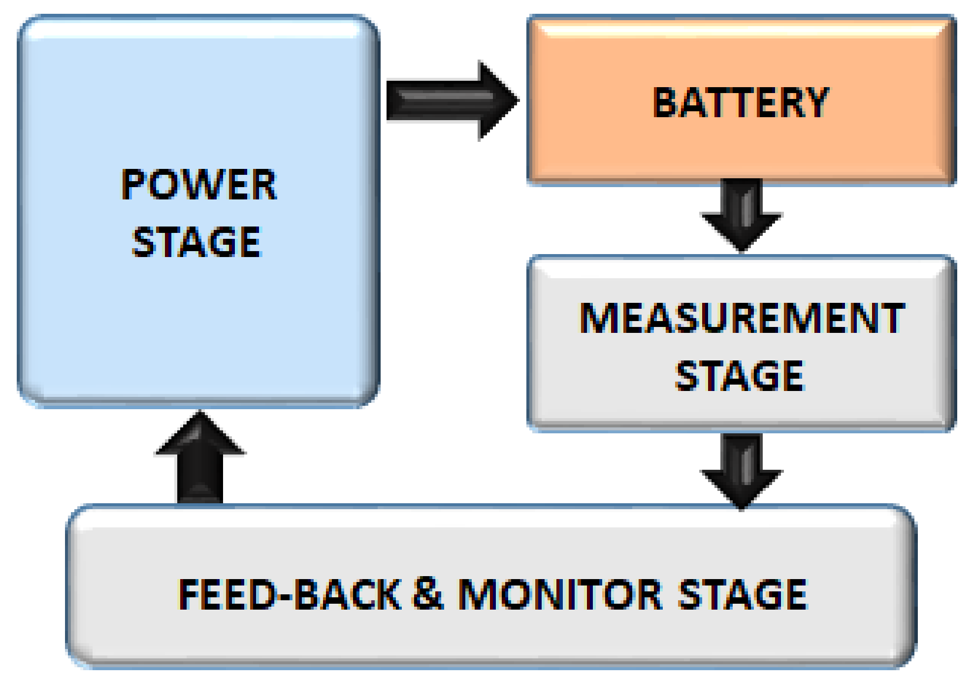
Nowadays, sustainable transportation in cities is a major goal to reach in order to reduce pollution. Thus, electrical vehicles (EVs) and light electrical vehicles (LEVs) are gaining more ground every day. The use of batteries reduces petrol consumption and pollution in the cities. On the other hand, the main drawbacks of EVs are battery autonomy, energy density, and, perhaps most important of all, charge time. While the refueling process of conventional vehicles lasts a couple of minutes, battery charging can last hours. During the last years, different battery types have appeared that have increased cycle life, energy density, and so on. In this way, lithium polymer batteries constitute a good solution [1,2]. As with other batteries, it is necessary to perform the charge process carefully, especially if fast-charge methods are used [3]. The evolution of high-power chargers for EVs and battery technologies run in parallel, usually involving resonant converters [4]. The battery type defines not only the battery charger but also the AC/DC converter used, especially in the case of on-board battery chargers [5]. Bearing in mind the application, battery chargers are required to be size- and weight-reduced, and at the same time, they must be able to cope with high power levels. Also, AC/DC converters are required to fulfil harmonic reduction IEC 1000-3-2, IEC 1000-3-3, and IEC 61000-3-2 standards.
Lately, drones (Figure 1) have experienced an important boom: they can accomplish surveillance tasks that would otherwise be either impossible or imply hazards to humans. For instance, inspection to prevent forest fires, monitoring difficult-to-access places, spy missions, and so on. These aircrafts can carry cameras, TV emitters, different sensors, and actuators, which makes it necessary to save power consumption.
Whatever the application, all of these LEVs include batteries that have to be charged under certain restrictions for voltage and power. For instance, lead (Pb) batteries require application of constant voltage, lithium ion (Li+) batteries require a current source, and so on. Presently, the most extended batteries for these LEVs are the lithium ion polymer (Li-Po) batteries.
These batteries exhibit high output power capability and are suited to drive the drone motors; the output currents are high (more than 100 A); on the other hand, it is necessary to survey carefully their temperature, since these kinds of batteries are very sensitive to this parameter. Figure 2 shows the temperature evolution of one of these batteries (Li-Po 6S) vs. time for several discharge current levels. Of course, the usual operation mode is not going to be constant current consumption; the temperature evolution with different consumption patterns is shown in Figure 3. Although the battery can supply the current in all the cases, it is also true that the battery can be ruined if its temperature increases beyond the limit; the larger the current value (constant or not), the faster the temperature increment. The patterns definition is summarized in Table 1.
In Figure 4, at the left, the typical current and voltage battery waveforms during this kind of test is shown; as it can be seen, as soon as the battery voltage drops below a certain level, the test has to be stopped immediately, otherwise the battery would be ruined. In the same figure, at the right, the workbench used is shown, constituted mainly by a water-cooled programmable load; this load enables discharge of the battery, with the aforementioned patterns, with great accuracy. As already mentioned, the previous tests evince that the larger the current value, the higher the temperature increment when current is kept constant, as it was expected. On the other hand, if the current consumption does not follow a constant value, it is also true that the lower the ripple, the lower the temperature. Similar conclusions can be obtained for the charge process; in fact, this kind of battery is charged by means of a constant current source (CCS) followed by applying a constant voltage source (CVS). On the other hand, it is necessary to keep in mind that different numbers of cells constitute the batteries, and it is mandatory to somehow equalize the charge of the different cells in order to avoid overcharging some of them.
Thus, the charge process is not as simple as it may seem. Figure 5 shows a diagram block of the different possible stages of a Li-Po charger. As it can be seen, the power stage must be able to work as constant current and as a constant voltage source, depending on the charge stage. As in other power equipment, it is desirable to obtain a reduced-size product, which involves implementing the power stage using high-frequency techniques; this usually leads either to resonant converters or another soft-switching techniques, otherwise, efficiency would penalize the final equipment size and weight.
In this work, the design and implementation of a power stage that can behave as a constant current or as a constant voltage source is presented.

2. Power Stage

2.1. Selection

It is possible to distinguish two different types of chargers: on-board (those which are included in the EV) and external. On-board chargers are preferred, since batteries are mainly charged from the public line. Their structure is basically constituted by two stages: an input current shaper for harmonic reduction followed by a dc/dc converter for output control and electrical isolation [3,6]. In [7], a power topology that comprises both stages was presented. Regarding the DC/DC converter, the series-parallel resonant converter and the parallel resonant converter are the most common topologies proposed in recent years [8,9]. These topologies allow fixed current/voltage and may even work at fixed frequency. In Figure 6, the general power topology, with an inductor as an output filter, and its main waveforms are presented. As can be seen, four switches form this topology in a full-bridge arrangement, a resonant tank, and the output rectifier and filter. This topology can be operated using the frequency, duty cycle, pulse density modulation as control parameter [10,11,12,13]. The main advantages of this topology are:
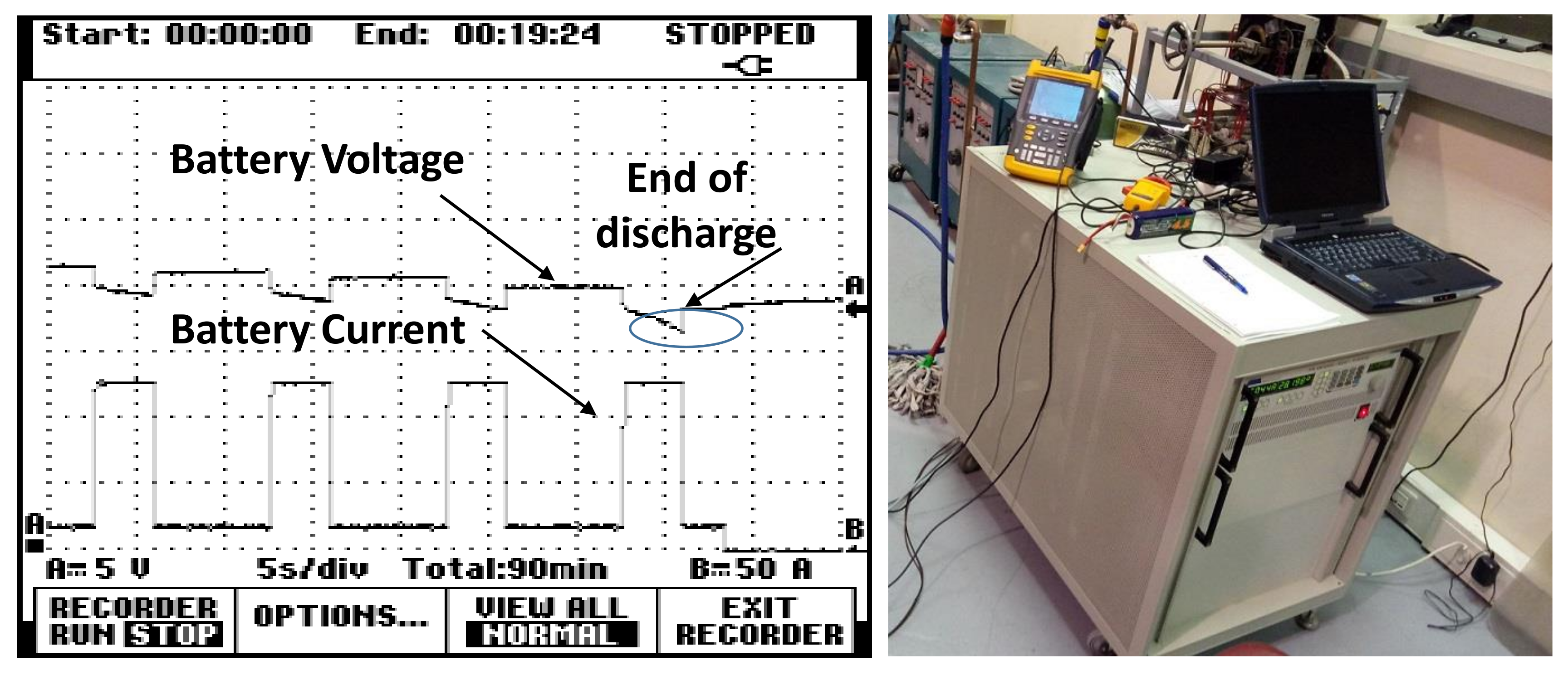
  • The topology is controlled as a constant current source, and once a certain voltage level is reached, it is possible to change to a constant voltage source operation mode without transient problems (current/voltage spikes, frequency changes); this is the typical control strategy for Li-Po batteries.
  • In order to increase the power stage efficiency, zero voltage switching (ZVS) is ensured in all the points, by means of frequency and duty cycle control, in both operating modes (CCS and CVS).
  • The transformer inclusion allows operation with different input and output voltages.
  • The topology allows the inclusion of transformer parasitic elements.
In the particular case of a battery charger, the output filter capacitor is no longer necessary; the resonant tank is constituted by series inductor (LS) and parallel capacitor (CP), and they can be implemented using parasitic transformer elements. As far as the output filter is concerned, it is inductive (LF). The load converter is now the battery. As can be seen in the waveforms, soft-switching is achieved, so the losses due to this concept are reduced. The waveforms are sinusoidal, and the output current is set by the duty cycle and the switching frequency.

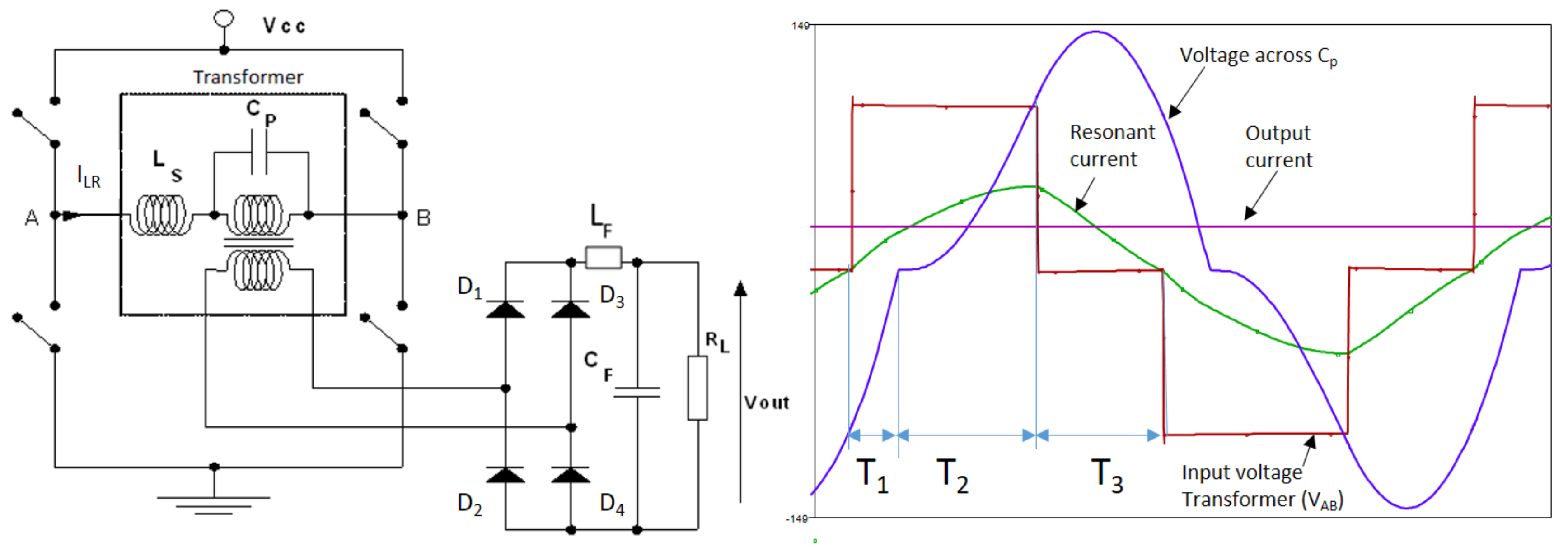
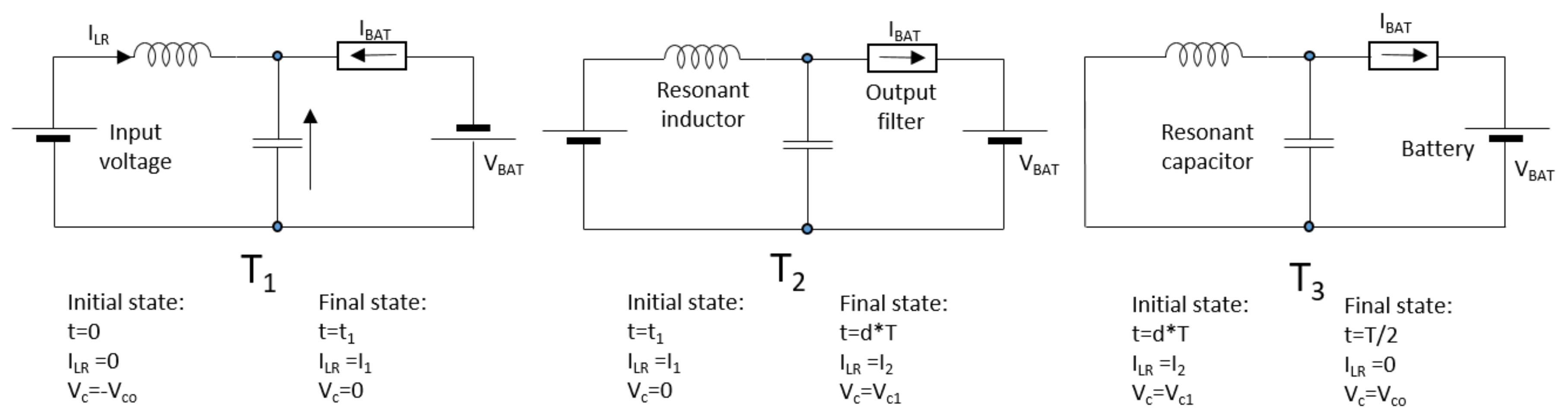
2.2. Topology Analysis and Design

The first choice that must be made is the selection of switches (MOST, IGBT), depending on different parameters: switching frequency, voltage and current range, losses, size of the components, and so on. Although it is very difficult to set general rules, it is possible to assert:
  • For frequencies above 70 kHz, the use of IGBTs is discouraged.
  • If the input voltage increases above 700 V, MOSFETs are discouraged.
  • For operating conditions out of the aforementioned limits, the selection must be silicon carbide MOSFETs, since they can operate at IGBTs’ voltage/current levels and MOSFETs’ frequencies. These devices can cope with higher losses, since the maximum junction operation range is around 200 °C, instead of 125 °C for silicon devices.
Whatever the selected switches, the goal of this block is generating a square waveform like the one shown in Figure 6 (variable duty cycle and frequency). This waveform is applied to the transformer, which filters this voltage in such a way that a sinusoidal current and voltage appear in the series inductor and at the parallel capacitor. Thus, a sinusoidal voltage also appears at the output, and it is applied to the rectifier + filter + load set.
In order to achieve ZVS operation mode, the topology will operate in such a way that the resonant current (ILR) crosses zero at the same time that the input voltage (VAB) goes from zero to ±Vcc; by doing so, not only is ZVS mode ensured for one leg, but zero reactive energy is handled as well. As can be seen in Figure 6, the power flows only in one direction (from input to output), and no spikes are detected in the switches. This operation mode is the one selected, and the one that will be the base for the topology analysis. In order to make things easier, the different stages (T1, T2, and T3 in Figure 6) are modeled by simple equivalent circuits, as shown in Figure 7. As usual, the following general rules are considered for the sake of simplicity:
  • The components are supposed to be ideal: neither resistors, nor parasitic capacitors/inductors, must be considered.
  • The secondary circuitry is transferred to the primary side.
  • The output current is constant; in other words, the output filter is ideal.
  • The circuit is in steady state; thus, the voltage/current values at the end of one period correspond to the initial conditions for the next one.
  • The input voltage is kept constant.
This method is widely used in static converter analysis and design; the expected results are a set of plots that assists in the selection of the proper values.
Since the waveforms are symmetrical, it is only necessary to consider half a period. As can be seen in Figure 6, the transformer has been removed and the filter and the load (the battery) have been replaced by current and voltage sources. Thanks to the filter inductor, the full-wave rectifier is always in the on state, and it is only necessary to modify the direction of the output current source and battery. As it can be seen, every stage is defined by either the voltage applied to the resonant tank or the voltage capacitor direction, which in turn defines which pair of diodes are in on state: D1 and D4 or D2 and D3. With the aim of obtaining general design plots, the equations are normalized using the following base values for voltage, impedance, and frequency:
V B = V C C
Z B = L C
f B = 1 2 · π · L · C
Using this base, and the equations that describe the different stages mentioned above, a set of equations is obtained, based on the variables defined in Figure 7:
i 1 = ( 1 + V c o ) · sin ( t 1 ) + I B A T ·   cos ( t 1 ) I i
( 1 + V c o ) · ( 1 cos ( t 1 ) ) + I B A T · sin ( t 1 ) V c o = 0
i 2 = sin ( d · T t 1 ) + ( i 1 I B A T ) · cos ( d · T t 1 ) + I B A T
V c 1 = ( 1 cos ( d · T t 1 ) + ( i 1 I B A T ) · sin ( d · T t 1 )
V c 1 · sin ( 0.5 · T d · T ) + ( i 2 I B A T ) · cos ( 0.5 · T d · T ) + I B A T = 0
V c o = V c 1 · ( 1 cos ( 0.5 · T d · T ) + ( i 2 I B A T ) · sin ( 0.5 · T d · T ) + V c 1
This system is completed with power balance: as the efficiency is considered to be 100%, the input power is the same as the output power. Output power can be easily calculated, since both magnitudes (voltage and current) are kept constant. As far as input power is concerned, it is necessary to consider that only during stages T1 and T2 is there power transfer in a no-reactive-energy mode, as intended. Finally, it is possible to solve the above system, as a function of duty cycle (d) and battery voltage (referred to the primary side).

2.3. Normalized Plots: Design

With the above system of equations, it is possible to collect the solution in a couple of plots, as Figure 8 shows. These graphs show the different relations between normalized parameters. Thus, the plot on the left represents—for different duty cycle values—normalized frequency (y-axis) vs. normalized output current (charge current) referred to the primary side (x-axis). The plot on the right represents—for different duty cycle values—battery voltage (y-axis) vs. output current (x-axis).
It must be noted that voltage battery is not going to increase very much: from 81% (discharged) to 116% (charged). The total variation is around 35%, and thus the most suitable operation area will be the one in which the voltage battery does not vary much, as happens in the shadowed area. Moreover, it is possible to work in this area in both operation modes (CC and CV). The vertical line (dashed red) represents the trajectory followed when the converter is operating as a current source; then, when the voltage reaches 1.15 (actually 115%), then the converter will operate as a constant voltage source. As it can be seen, within this range it is possible to operate the power stage in the described operation mode. If it were necessary to extend the operation range, especially to decrease the current, other control strategies could be adopted.
The design process can be summarized by the next steps, with battery voltage going from 12 V to 16.618 V, and a charge current equal to 4 A.
  • Select a suitable value for the transformer ratio.
    It should be noted that the VBAT and IBAT magnitudes are referred to the primary side. So, as soon as the normalized voltage battery value is selected, the transformer ratio is also selected. In other words, if a value of 0.81 is selected for the minimum battery voltage (let us say, 12 V), we have:
    V B A T M I N = 0.81 = 12 · r t V c c
    Using this equation, it is possible to adjust the transformer ratio, rt, provided Vcc is fixed. As a consequence, the value of VBATMAX in normalized values can be obtained.
  • Select the value for the base impedance, provided the charge current is known.
    The normalized value for the charge current is 1.15. If we assume that the charge current is set, for instance, to 4 A:
    1.15 = I B A T = 4 · r t V C C L C
    From (11) it is possible to determine the base impedance value, ZB.
  • Obtain the normalized value for the maximum battery voltage:
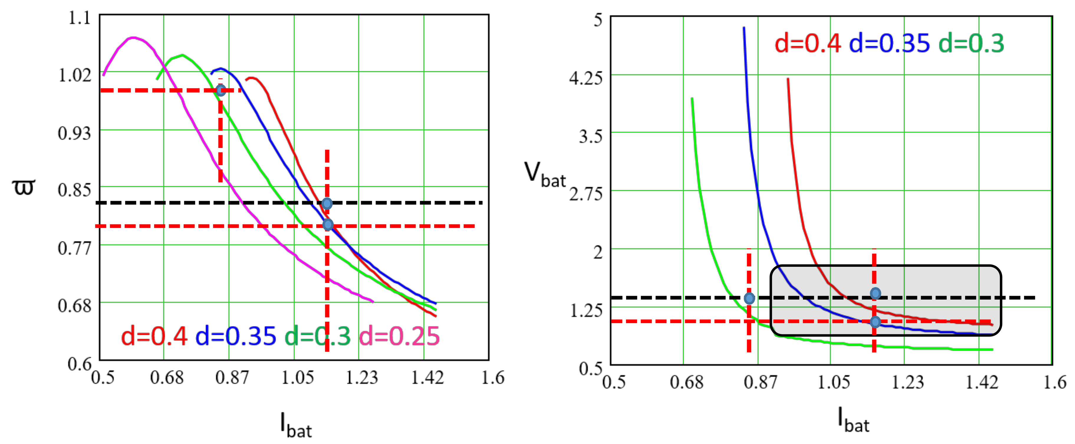
    V B A T M A X = 16.618 · r t V c c = 1.12
  • Set the maximum (or minimum) frequency.
    Using Figure 8, the plot on the right can be used to set the minimum current value to switch the charger off; once this current and the corresponding duty cycle are known, the plot on the left determines the ϖ values. In the example represented in Figure 8 (see plot on the right), the converter starts operating in constant current mode (IBAT = 4 A; IBAT = 1.15, normalized) and the operation point moves vertically until the maximum battery voltage is reached (VBAT = 16.618 V; VBAT = 1.12, normalized). From that point on, the charger operates in constant voltage mode and the operation point moves horizontally until the minimum acceptable current is reached (IBAT = 2.887 A; IBAT = 0.83, normalized). By plotting these points on the plot on the left in Figure 8, the evolution of the switching frequency can be determined. When the charger reaches this minimum operating current, the strategy must be modified in order to reduce the current to a trickle charge value, for instance:
    ω M A X = 0.98 ;   f M A X = 0.98 2 · π · L · C
    Equation (13) allows values L and C to be derived, since impedance base is known by Equation (11). This completes the topology design.

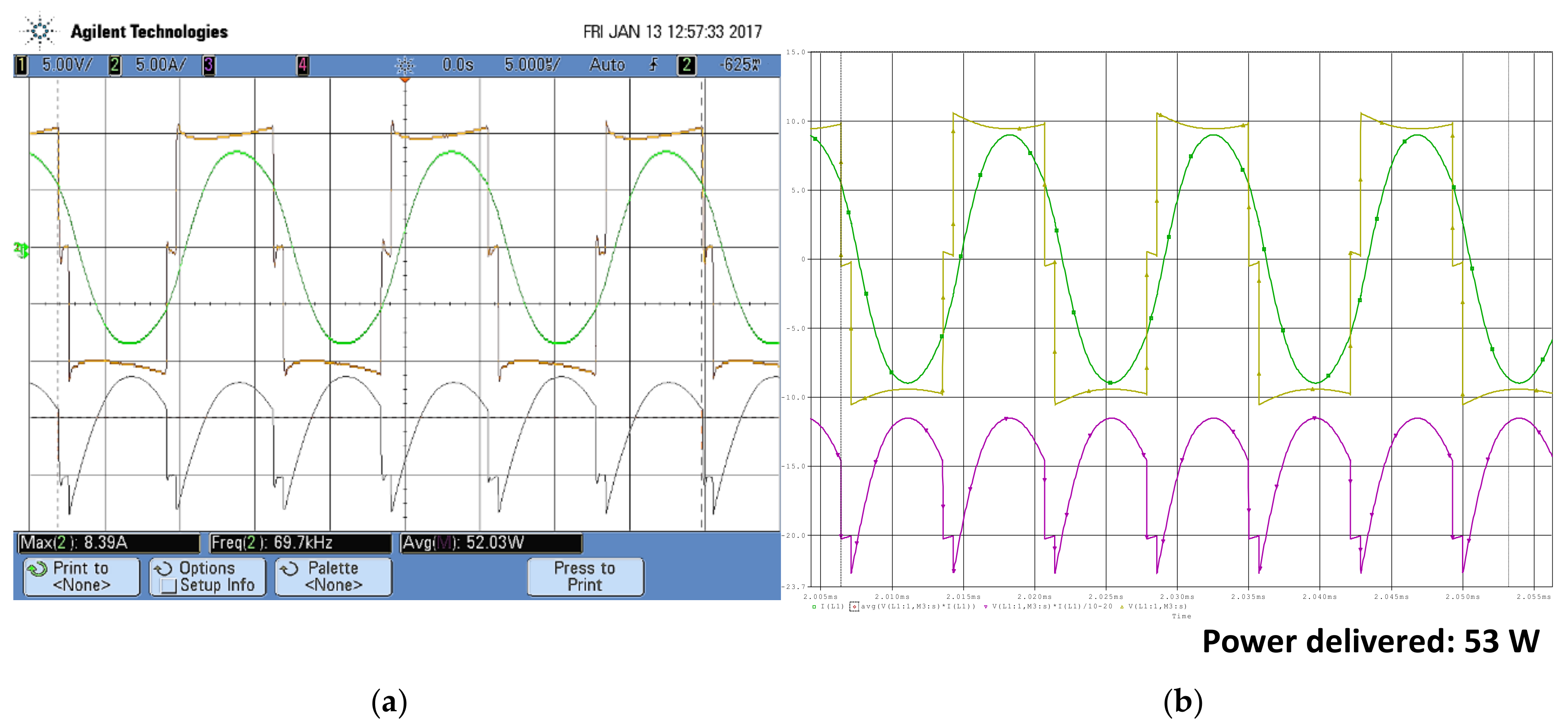
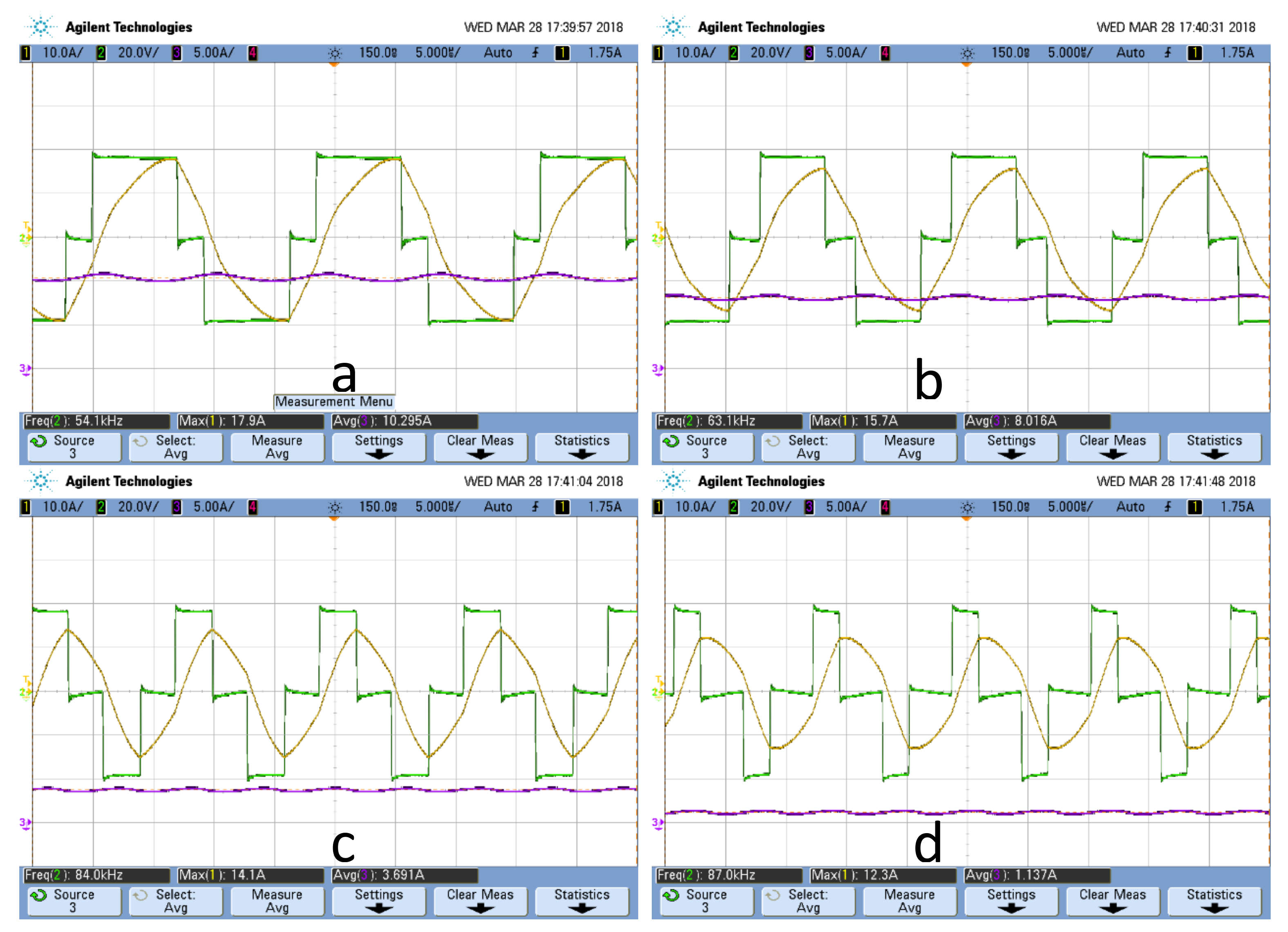
3. Simulation and Experimental Results

In order to validate the analysis and the feasibility of the proposed power stage, a prototype has been built, using MOS transistors, and its behavior has been simulated. The results match those in the theoretical analysis, as was expected. The prototype specifications are:
  • Input voltage: 12 V
  • Maximum battery voltage: 16.8 V, minimum 12 V
  • Output current: 4 A
  • Switching frequency: 70 kHz
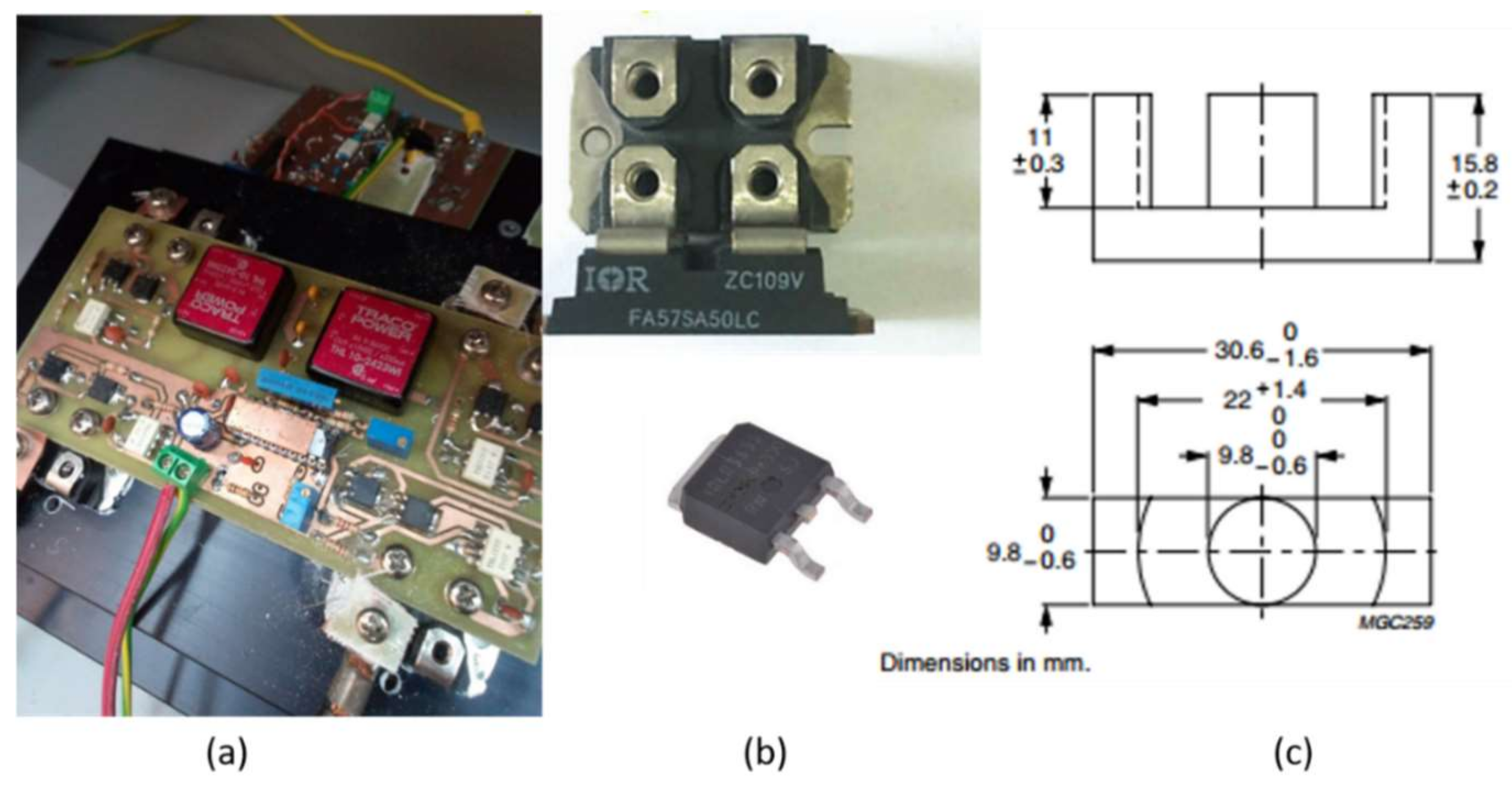
  • MOSFETS: IRLU3636PBF, 60 V, 99 A, Rdson = 5.4 mΩ.
  • Resonant and Filter Inductors: Material 3F3, core ETD34/17/11.
If the input voltage comes from the mains, it is necessary to include a suitable step-down transformer, and select other switches that can withstand the input voltage. In Figure 9, a photo (Figure 9a) of a power stage that fulfills these specifications is shown. In Figure 9b, the MOS transistors for both converters (with and without step-down transformer) are shown. In Figure 9c, the core dimensions are shown for both inductors (resonant and filter).
Regarding the batteries, the power stage has been tested charging these batteries:
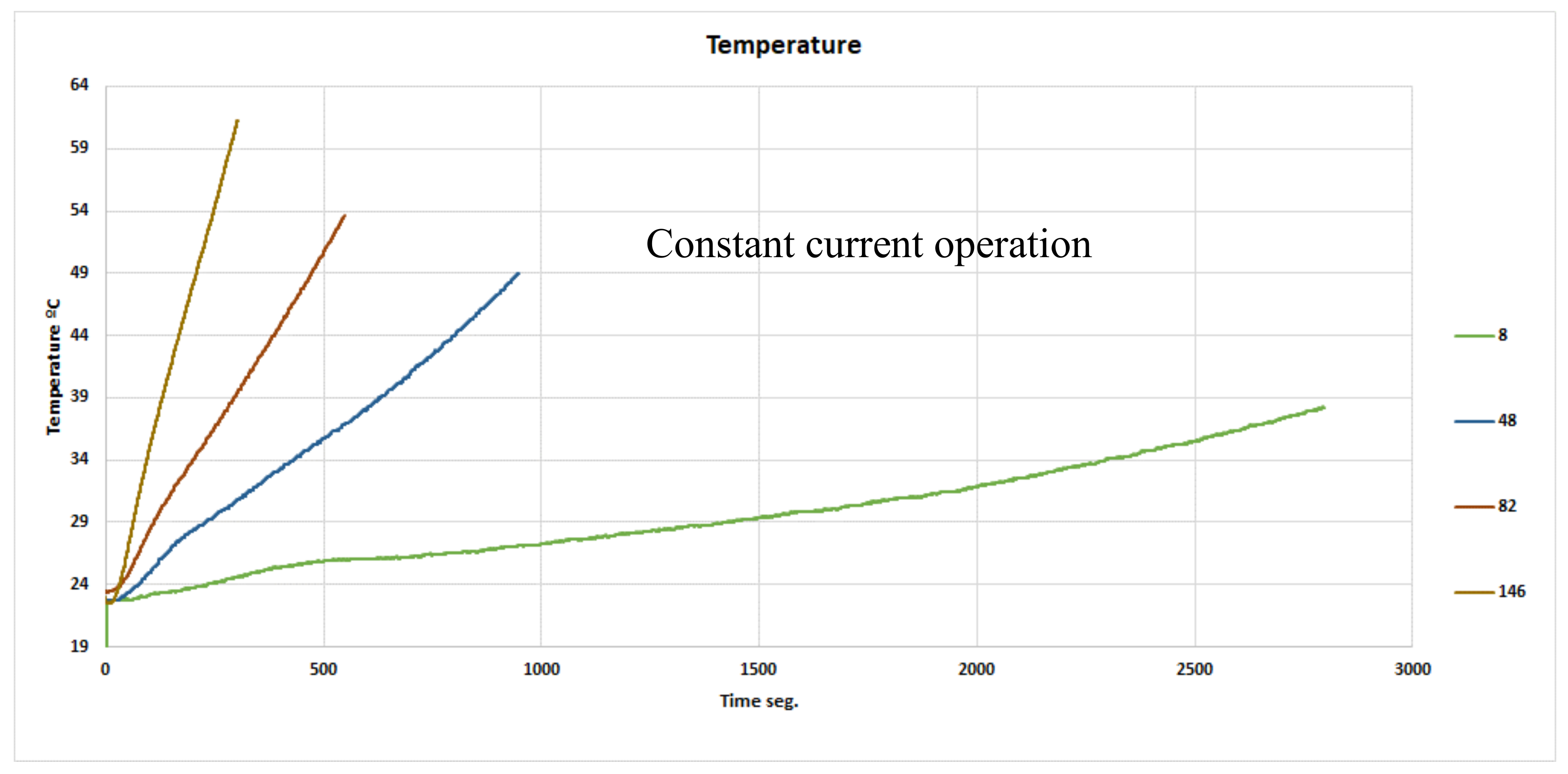
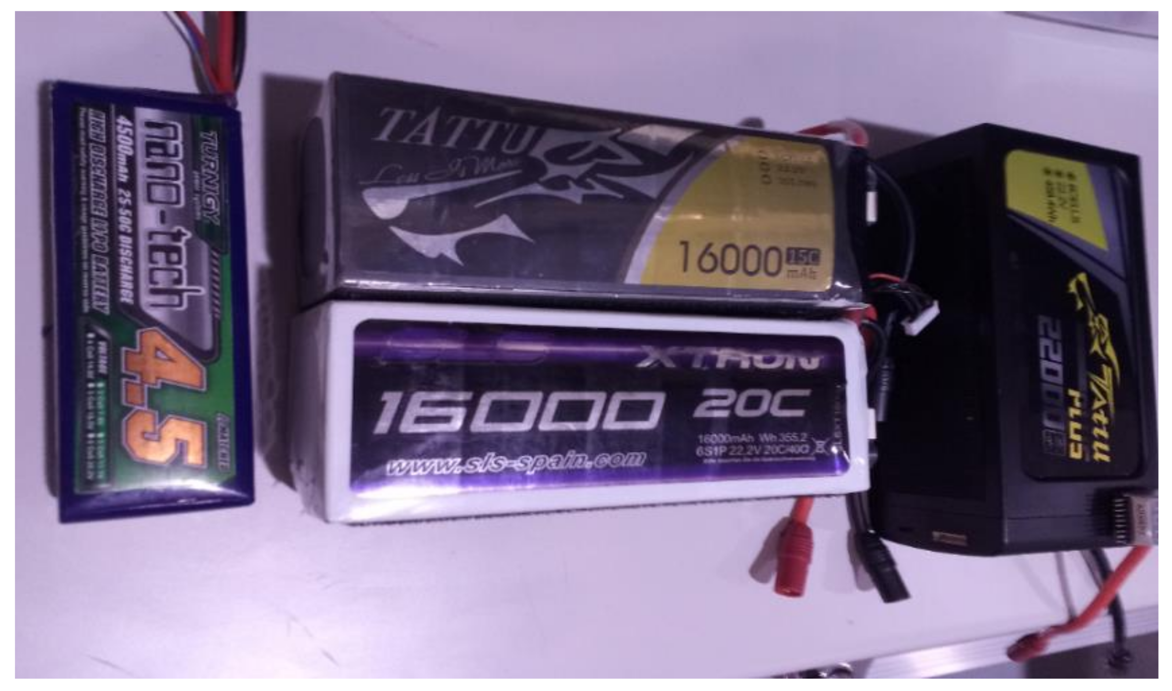
  • 4S 4500 mAh, 25–50 C discharge peaks; 14.8 V, nominal charge current: 4 A, fast charge 8 A.
  • 6S 16,000 mAh 20 C discharge peaks; 22.2 V, nominal charge current: 16 A, fast charge 32 A.
  • 62 22,000 mAh 25 C discharge peaks; 22.2 V, nominal charge current 22 A, fast charge 44 A.
In Figure 10, some of the batteries used to test the power stage are shown.
With the aforementioned specifications, the power converter parameters obtained are (assuming duty cycle = 0.4 for the maximum power point):
I B = 12 L C V B = 12 = > V B A T M A X = 1.4 ; V B A T M I N = 1
I n = 1.07 = > 4 = 1.07 · 12 L C ;   I n = 1.07 = > ω = 0.87201 =   > 70000 = 0.87201 2 · π · L · C
which compute to an inductor value of 7 µH and a value for the capacitor of 617 nF. For the filter inductor, a value 10 times higher (minimum) has been selected (70 µH).
Simulation results and experimental results for the prototype are shown in Figure 11; as it can be seen, both plots match pretty well. The differences between simulation and experimental results are minimum and are caused by SPICE models, among others.
The current in the battery can be easily changed by modifying the frequency and duty cycle, as shown in Figure 12 plots; output current goes from 10 A (Figure 12a) to 1 A (Figure 12d), with a frequency excursion from 54 kHz to 87 kHz. In all the range, ZVS operation mode was achieved.
Since the battery voltage does not change fast, the frequency/duty cycle change smoothly too, and no current or voltage spikes are detected.

4. Discussion

Li-Po batteries exhibit great energy density and are widely used in LEVs such as drones, electric motorbikes, and others. They do not present memory effect and can be connected in different arrangements, thus enabling different capacities and size. On the other hand, they require a careful charge process that involves the use of a CCS and a CVS, depending on the actual battery voltage. This requires a power stage able to behave in both operation modes and to change from one to another without problems.
The parallel resonant converter with an output filter inductor operates in both modes and can jump from current source to voltage source operation without spikes or important changes in frequency and/or duty cycle. Furthermore, the topology can be designed with a transformer, which provides great flexibility for the input power source: the power stage can be connected to the mains, to another battery, etc. Since the topology operates in ZVS mode, the overall efficiency is high (over 90%), with high stability. The input power has been measured from the input power source to the battery terminals
The design was facilitated by means of normalized plots and can be carried out in a few of steps, while ensuring zero reactive energy and ZVS operation mode.

Acknowledgments

This work has been subsidized through the Plan of Science, Technology and Innovation of the Principality of Asturias, (Ref: FC-15-GRUPIN14-122) and Spanish Government with the action TEC2016-77738-R.

Author Contributions

José Á. Fernández-Rubiera and Manés Fernández-Cabanas performed the discharge tests under different patterns, Juan Díaz-González, Alberto M. Pernía obtained the topology plots, and performed the simulations, Miguel J. Prieto and Fernando Nuño-García collaborated in the prototype design & development and in the power tests.

Conflicts of Interest

The authors declare no conflict of interest.

References

  1. Eddahech, A.; Briat, O.; Al Jed, H.; Chaari, R.; Mieze, A.; Simon, R.; Vinassa, J.M. Li-Po Batteries Modeling for Mail Delivery Electric Vehicles. In Proceedings of the 2011 IEEE Vehicle Power and Propulsion Conference, Chicago, IL, USA, 6–9 September 2011; pp. 1–5. [Google Scholar]
  2. Ananto, P.; Syabani, F.; Indra, W.D.; Wahyunggoro, O.; Cahyadi, A.I. The State of Health of Li-Po Batteries Based on the Battery’s Parameters and a Fuzzy Logic System. In Proceedings of the 2013 Joint International Conference on Rural Information & Communication Technology and Electric-Vehicle Technology (rICT & ICeV-T), Bandung-Bali, Indonesia, 26–28 November 2013; pp. 1–5. [Google Scholar]
  3. Chi, H.T.Q.; Park, D.H.; Lee, D.C. An Advanced Fast Charging Strategy for Lithium Polymer Batteries. In Proceedings of the 2015 IEEE 2nd International Future Energy Electronics Conference (IFEEC), Taipei, Taiwan, 1–4 November 2015; pp. 1–6. [Google Scholar]
  4. Cai, G.; Liu, D.; Liu, C.; Li, W.; Sun, J. A High-Frequency Isolation (HFI) Charging DC Port Combining a Front-End Three-Level Converter with a Back-End LLC Resonant Converter. Energies 2017, 10, 1462. [Google Scholar] [CrossRef]
  5. Hegazy, O.; Van Mierlo, J.; Barrero, R.; Lataire, P.; Omar, N.; Coosemans, T. A Comparative Study of Different Control Strategies of On-Board Battery Chargers for Battery Electric Vehicles. In Proceedings of the 2013 Eighth International Conference and Exhibition on Ecological Vehicles and Renewable Energies (EVER), Monte Carlo, Monaco, 27–30 March 2013; pp. 1–6. [Google Scholar]
  6. Lee, J.Y.; Yoon, Y.D.; Kang, J.W. A Single-Phase Battery Charger Design for LEV Based on DC-SRC With Resonant Valley-Fill Circuit. IEEE Trans. Ind. Electron. 2014, 62, 2195–2205. [Google Scholar] [CrossRef]
  7. Hegazy, O.; Van Mierlo, J.; Lataire, P. Design and Control of Bidirectional DC/AC and DC/DC Converters for Plug-In Hybrid Electric Vehicles. In Proceedings of the 2011 International Conference on Power Engineering, Energy and Electrical Drives, Malaga, Spain, 1–13 May 2011; pp. 1–7. [Google Scholar]
  8. Chuang, Y.C.; Ke, Y.L.; Chuang, H.S.; Chen, Y.M. Analysis and Implementation of Half-Bridge Series–Parallel Resonant Converter for Battery Chargers. IEEE Trans. Ind. Appl. 2011, 47, 258–270. [Google Scholar] [CrossRef]
  9. Gücin, T.N.; Biberoğlu, M.; Fincan, B. Constant-Current Constant-Voltage Charging Based Control and Design Approach for the Parallel Resonant Converter. In Proceedings of the 2015 International Conference on Renewable Energy Research and Applications (ICRERA), Palermo, Italy, 22–25 November 2015; pp. 414–419. [Google Scholar]
  10. Steigerwald, R.L. A comparison of half-bridge resonant converter topologies. IEEE Trans. Power Electron. 1988, 3, 174–182. [Google Scholar] [CrossRef]
  11. Tanaka, J.; Yuzurihara, I.; Watanabe, T. Analysis of a full-bridge parallel resonant converter. In Proceedings of the Thirteenth International Telecommunications Energy Conference—INTELEC 91, Kyoto, Japan, 5–8 November 1991; pp. 302–307. [Google Scholar]
  12. Swamy, M.M. Analysis, Design, and Optimization of a Fixed-Frequency Parallel Resonant converter. In Proceedings of the 1992 International Conference on Industrial Electronics, Control, Instrumentation, and Automation, San Diego, CA, USA, 9–13 November 1992; pp. 166–172. [Google Scholar]
  13. Diaz, J.; Saiz, P.J.V.; Martin-Ramos, J.A.; Martin-Pernia, A.; Martinez, J.A. A High-Voltage AC/DC Resonant Converter Based on PRC With Single Capacitor as an Output Filter. In Proceedings of the IEEE transactions on Industry Applications, Houston, TX, USA, 4–8 October 2009; Volume 46, pp. 2134–2141. [Google Scholar]
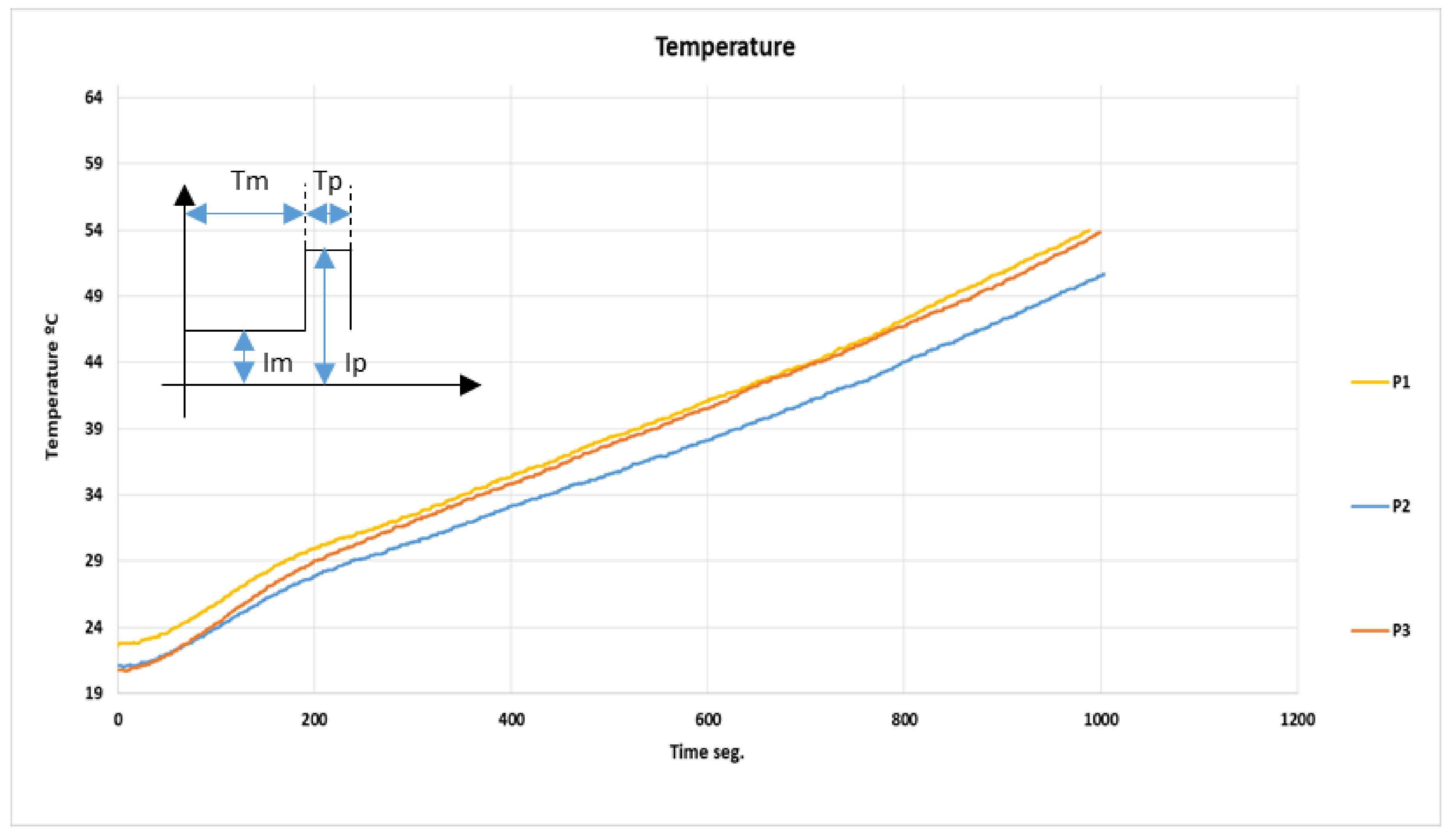
Figure 1. Drone for surveillance missions equipped with camera, GPS, and TV emitter.
Energies 11 00951 g001
Figure 2. Battery temperature vs. time for several constant current levels (8–140 A).
Energies 11 00951 g002
Figure 3. Battery temperature for several discharge patterns.
Energies 11 00951 g003
Figure 4. Typical waveforms during tests (pattern 1) and water-cooled programmable load used during tests.
Energies 11 00951 g004
Figure 5. Battery charger block diagram; this work focuses on power stage.
Energies 11 00951 g005
Figure 6. Power topology and main waveforms: voltage at the transformer input (red), current through series inductor Ls (green), and voltage across the parallel capacitor (violet) and output current (pink).
Energies 11 00951 g006
Figure 7. Equivalent circuits in the different stages, with initial and final state definitions.
Energies 11 00951 g007
Figure 8. Power topology normalized plots: all the magnitudes are referred to the primary side, according to the simplified circuits. The preferred operation area and a possible trajectory are also shown.
Energies 11 00951 g008
Figure 9. (a) Power stage, suitable for mains operation; (b) different switches; (c) core dimensions for the inductors.
Energies 11 00951 g009
Figure 10. Different batteries used in power tests (discharge/charge).
Energies 11 00951 g010
Figure 11. Experimental results (a) and simulation results (b). The efficiency is above 90% in the operation range. Battery 4S 4500 mAh, 25–50 C.
Energies 11 00951 g011
Figure 12. Different output current values, obtained with different frequency/duty cycle values (battery 6S 16,000 mAh 20 C), (a) 54.1 KHz; (b) 63.1 KHz; (c) 84 KHz; (d) 87 KHz.
Energies 11 00951 g012
Table 1. Patterns definition for the discharge tests at variable current.
ParameterPattern 1Pattern 2Pattern 3
Tm6 s8 s9 s
Tp3.5 s2 s1 s
Im20 A34 A32 A
Ip110 A110 A200 A

