Article

State-of-Charge Balancing Control of a Modular Multilevel Converter with an Integrated Battery Energy Storage

1
National Active Distribution Network Technology Research Center (NANTEC), Beijing Jiaotong University, Beijing 100044, China
2
Collaborative Innovation Center of Electric Vehicles in Beijing, Beijing Jiaotong University, Beijing 100044, China
3
Huawei Technologies Co., Ltd, Shenzhen 518000, China
4
CRRC Industrial Institute Co., Ltd., Beijing 100071, China
*
Author to whom correspondence should be addressed.
Energies 2018, 11(4), 873; https://doi.org/10.3390/en11040873
Submission received: 5 March 2018 / Revised: 1 April 2018 / Accepted: 4 April 2018 / Published: 9 April 2018
(This article belongs to the Special Issue Power Electronics in Renewable Energy Systems)

Abstract

:
With the fast development of the electric vehicle industry, the reuse of second-life batteries in vehicles are becoming more attractive, however, both the state-of-charge (SOC) inconsistency and the capacity inconsistency of second-life batteries have limits in their utilization. This paper focuses on the second-life batteries applied battery energy storage system (BESS) based on modular multilevel converter (MMC). By analyzing the power flow characteristics among all sources within the MMC-BESS, a three-level SOC equilibrium control strategy aiming to battery capacity inconsistency is proposed to balance the energy of batteries, which includes SOC balance among three-phase legs, SOC balance between the upper and lower arms of each phase, and SOC balance of submodules within each arm. In battery charging and discharging control, by introducing power regulations based on battery capacity proportion of three-phase legs, capacity deviation between the upper and lower’s arm, and the capacity coefficient of the submodule into the SOC feedback control loop, SOC balance of all battery modules is accomplished, thus effectively improving the energy utilization of second-life battery energy storage system. Finally, the effectiveness and feasibility of the proposed methods are verified by results obtained from simulations and the experimental platform.

1. Introduction

With the fast-growing commercial application of electric vehicles, there will be a substantial increase of the batteries retired from these vehicles, leading to a great waste of resources if the batteries are directly thrown out. By expanding the useful life of these retired batteries for second use, the total battery life cycle cost can be easily reduced and the utilization of the battery could also be greatly improved [1], which is of great significance to promote the replaceable developments of the electric vehicle industry. The most economical way of reusing second-life batteries is the battery energy storage system (BESS). In conventional battery energy storage systems, a large number of batteries are connected in series or in parallel in a battery pack, which requires a higher battery consistency in practical applications. However, due to the high capacity inconsistency and high cost of module reconstruction in second-life batteries, the large number of series/parallel applications and “short-board” effect will reduce the total capacity utilization of the energy storage system, which will affect the energy and capacity utilization efficiency.
Flexible group technology is an effective method to solve the problem of the high battery inconsistency [2,3]. Different from the conventional battery group composed of a large number of single batteries directly connected in series and in parallel, the flexible group energy storage system is consist of cascaded submodules combining the low-voltage battery pack with converters. Charging or discharging the current of each battery module is controlled independently based on the state parameters, effectively reducing the requirement of battery capacity consistency and the cost of regrouping. Thus, the capacity utilization efficiency and cycle life of batteries can be improved while meeting the requirements of energy storage systems. Consequently, the efficient utilization of the retired power batteries is realized.
Various topologies can be used in flexible group energy storage system [4,5]. In the application where power flows among the AC grid, the DC bus and battery, the MMC-BESS has its superior advantages of overcoming the “short-board” effect. By dispersedly connecting the low-voltage battery pack to the DC side of each submodule, this topology combines the merits of both MMC and BESS, which is suitable for hybrid AC/DC micro-grids and high-voltage direct current (HVDC) power system. Meanwhile, advanced modeling [6,7,8], control systems, and modulation [9,10] has developed MMC greatly. The battery capacity utilization of the whole MMC-BESS is limited by the submodule with the highest or lowest state of charge (SOC), therefore the SOC equilibrium control becomes the essential part of improving battery capacity utilization. Since SOC is directly related to battery capacity, the capacity inconsistency can easily result in divergent real-time SOC. When second-life batteries are widely used in battery packs in MMC-BESS, in addition to capacity inconsistency of batteries in the same arm, the total battery capacity between the upper and lower arm as well as the total capacity among different phases are also inconsistent, leading to greater SOC inconsistency at each level of battery modules. Thus, the conventional SOC equilibrium control strategy has limited applications and new control methods are in great urge.
SOC balancing control and fault-tolerant control are essential for the MMC-BESS to improve the efficiency and reliability of capacity utilization. In Reference [11], the zero-sequence voltage injection method is able to balance the SOC among different phases, however, the calculation of zero-sequence voltage injection involves complex mathematical calculation, leading to higher requirement of control hardware. By sorting the SOCs of all submodules, SOC balancing control can be realized using the carrier-based disposition pulse width modulation (PWM) method [12]. However, the complexity increases dramatically with the increase of the number of submodules. Reference [13] proposed a simple and easy closed-loop method to achieve SOC balancing among submodules within an arm and phase legs, while the SOC balancing problem between the upper and lower arms is not under full consideration. Some literature focuses on the MMC-BESS applied in vehicles, in which using AC-circulating current to balance SOC between the lower and upper arms; the current only contain positive sequence and negative sequence to protect the current from flowing to the DC source [14]. As SOH can also be used to improve utilization of battery, the author adopted dc and ac circulating current as well as modulation index of each submodule to achieve the tracking of SOC, thus effectively improving the cycle time of battery system [15]. In [16], the capacity energy in both upper and lower arm can be controlled by adjusting the circulating current after bypassing the fault submodule, resulting in the SOC rebalancing even under fault operation. Reference [17] focuses on the hybrid MMC energy storage system consisting of half-bridge and full-bridge topologies, which highly integrating different voltage and current injection methods for both interphase and intra-phase SOC equalization. Although various SOC equilibrium control methods were proposed in the previous literature, the impact of capacity inconsistency has not been fully considered. In the condition where the inconsistency index goes higher, the control error may turn greater, resulting in lower battery capacity utilization.
To overcome the shortage of conventional SOC equalization methods under the operation of battery capacity inconsistency, after the analysis of the power transfer relationship of MMC-BESS, this paper proposes a three-level SOC balancing control strategy. The SOC closed-loop control strategy is implemented to adjust the power command from phase level to each submodule, and then regular both the DC circulating current and AC current. By respectively adjusting the phase power and arm power, the power of submodules can be reconfigured. To solve the battery capacity inconsistency problem, this paper proposed a novel control method based on power regulations and SOC equalization control to synchronously converge the SOC equilibrium among different battery packs with various battery capacity, and eventually achieves the goal of the same SOC of all battery modules of MMC-BESS, effectively improving the utilization of second-life batteries. Both the simulation model and experimental platform of a three-phase 24-module energy storage system have been established to verify the effectiveness of the proposed control strategy.

2. Operating Principles

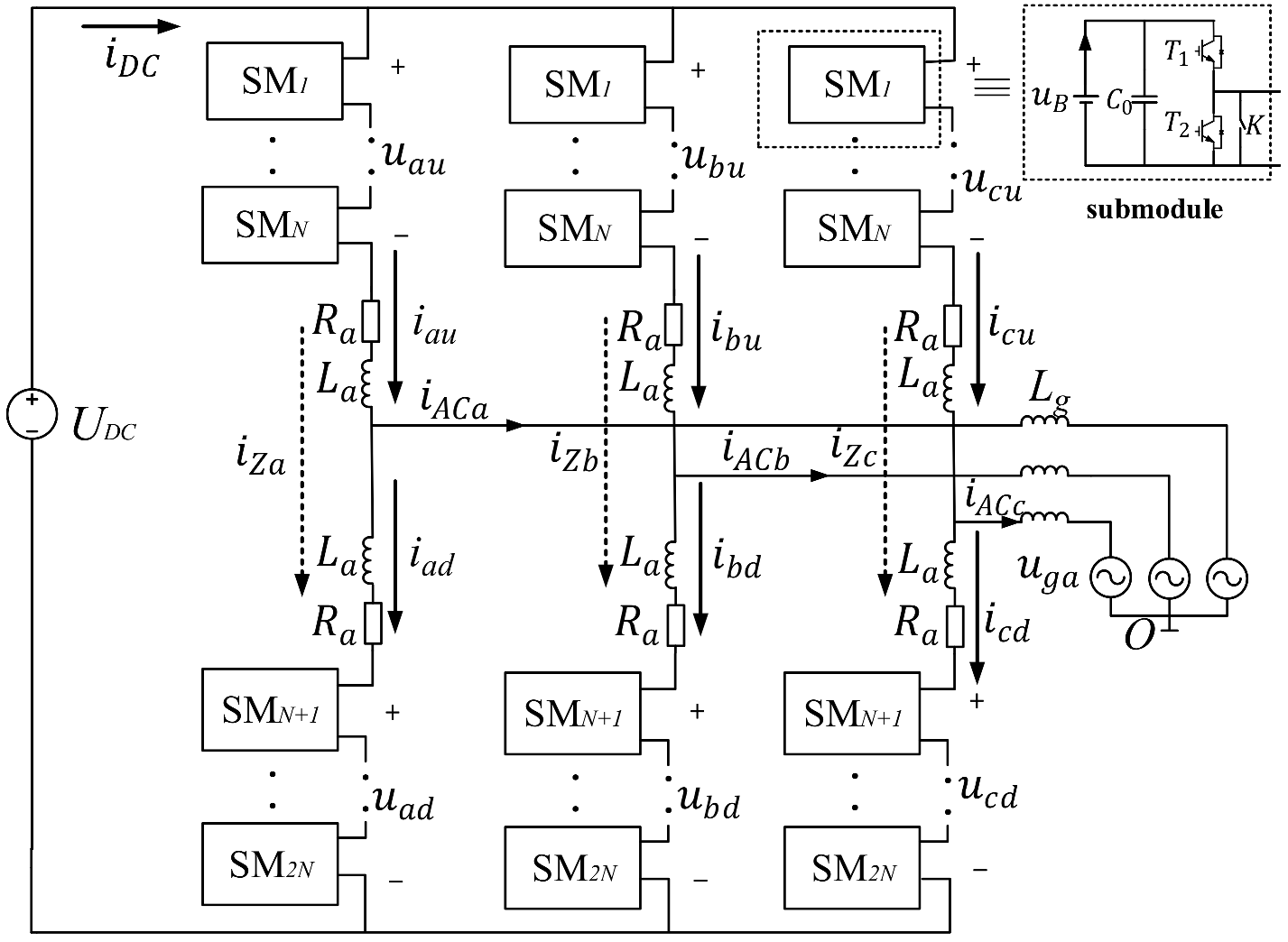
2.1. Topology and Modulation Strategy

The schematic diagram of the MMC-BESS is shown in Figure 1. Three-phase legs are connected in parallel to a common DC grid and the midpoint is connected to an AC grid through the grid inductor Lg. Each leg consists of upper and lower arms, the arm inductor La and equivalent series impedance Ra. There are N cascaded submodules in each arm, where low-voltage battery packs and half bridge are embedded. The bypass switch of each submodule will be closed once a failure in this submodule happens. The power devices T1 and T2 are in complementary operation, which means the submodule cannot output negative voltages. Some researchers add DC-DC converter between battery and half bridge to reduce the current ripple of battery [18].
The driving signals of the power devices are generated by the carrier phase shift modulation in this paper. A schematic diagram of the carrier phase-shift modulation strategy is shown in Figure 2. N carrier signals for the submodules within the same arm have a 2π/N phase shift. The reference voltage for the upper and lower arms are opposite in phase. In this way, the output voltage of the converter has 2N + 1 levels and its dominant harmonic component is 2N·fSW. Therefore, the harmonic performance is acceptable even at a low switching frequency.

2.2. Power Flow Analysis

MMC-BESS is a three-port power converter system connected to the AC grid, the DC link, and the batteries. The power flow analysis is the basis of the control strategy design. The high-frequency component of the voltage and current is neglected in this paper for better analysis. In the following discussion, j ∈ {a, b, c} represents different phases, k ∈ {u, d} refers to the upper and lower arms of the same phase leg, and i ∈ {1, 2, …, N} represents the number of submodules located in one arm.
As described in Reference [14], the output voltage of submodule ujki consists of three parts: the AC grid component uACjki, the DC circulating component uDCjki, and the AC circulating component uXjki. Since most of the second harmonic current flows through the batteries, the second harmonic circulating current can be neglected in this system [19]. The AC components of the submodules output voltage (including uACjki and uXjki) in the same arm have the same phase angle. To keep the symmetrical system, the total upper arm voltage and the total lower arm voltage should be presented as follows:
u j u = i = 1 N u j u i = u D C j + u X j u A C j u j d = i = 1 N u j d i = u D C j + u X j + u A C j
where uACj is the drive voltage of the AC current iACj. uDCj is the DC drive voltage of the DC circulating current iDCj and uDCjUDC/2 when Ra is small enough. uXj is the drive voltage corresponding to the AC circulating current iXj. The arm currents ijk are composed of these three components accordingly:
i j u = i D C j + i X j + i A C j 2 i j d = i D C j + i X j i A C j 2
iDCj and iXj compose the circulating current iZj, which is a common component in both the upper and lower arms:
i Z j = i j u + i j d 2 = i D C j + i X j
After applying the KVL method to the system in Figure 1, the following relationships are found:
L a d i X j d t + i X j R a = u X j 2 i D C j R a = U D C 2 u D C j ( L a 2 + L g ) d i A C j d t + R a 2 i A C j = u g j u A C j
Assuming that all submodules in the same arm can be regard as a single module, then the total output active power is equal to the total arm battery power. By multiplying the voltage components in Equation (1) and current components in Equation (2) one by one, all of the instantaneous active power and reactive powers can be found. Only the average active power is studied in this paper and the total arm battery power of the upper and lower arms, P Bju and P Bjd, result in the following equations:
p B j u = i D C j U D C 2 i ^ g j u ^ A C j 2 cos θ + ( i ^ X j u ^ AC j 2 cos ϕ 1 + i ^ g j u ^ X j 2 cos ϕ 2 ) p B j d = i D C j U D C 2 i ^ g j u ^ A C j 2 cos θ ( i ^ X j u ^ A C j 2 cos ϕ 1 + i ^ g j u ^ X j 2 cos ϕ 2 )
where θ and φ2 are the phase angles of IACj, corresponding to UACj and UXj, respectively. φ1 is the phase angle of IXj and UACj. The third term in Equation (5) is the AC circulating power yielded by the AC circulating current IXj and voltage UXj. Though IXj is usually considered the current generating power loss, it is employed to shift power between arms in the same phase.
The expressions of the battery pack power of each submodule in the upper and lower arms, PBjui and PBjdi, are similar to Equation (5). This results in the following relationships:
P B j u i = I D C j U D C j u i i ^ g j u ^ A C j u i 2 cos θ + ( i ^ X j u ^ A C j u i 2 cos ϕ 1 + i ^ g j u ^ X j u i 2 cos ϕ 2 ) P B j d i = I D C j U D C j d i i ^ g j u ^ A C j d i 2 cos θ ( i ^ X j u ^ A C j d i 2 cos ϕ 1 + i ^ g j u ^ X j d i 2 cos ϕ 2 )
Comparing Equation (5) with Equation (6), it is clear that when the magnitude of the three voltage components of Ujki is proportional to the corresponding components of the total arm output voltage Ujk with the factor ki, the battery power PBjki is also proportional to the total arm battery power PBjk with ki. Thus, the battery power of each submodule in an arm can be distributed by adjusting the output voltage ratio ki.
Based on Equation (5), the total leg battery power is derived from the following:
p B j = p B j u + p B j d = p D C j p g j = i D C j U D C i ^ g j u ^ A C j cos θ
To keep the grid currents balanced, each grid power PACj is made equal. Therefore, PBj can be changed by managing the DC circulating current IDCj. The power transfer between the upper and lower arm batteries can be controlled by modifying the AC circulating current IXj and the individual battery power in the same arm can be controlled by adjusting the output voltage ratio ki. In this way, the individual power control of each battery pack can be achieved.

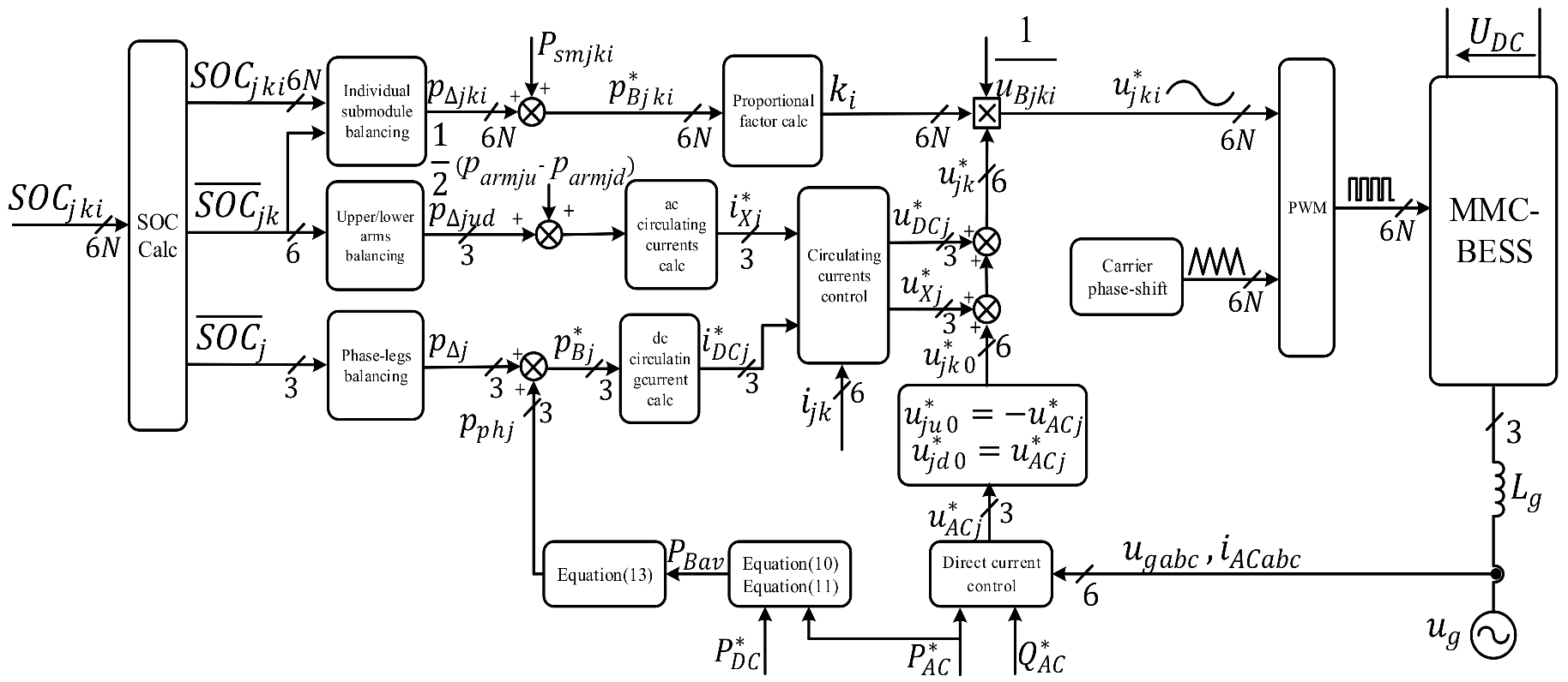
3. SOC Balancing Control Strategy

During the operation of the BESS, the SOCs of the battery packs will gradually become unequal, which will decrease the capacity utilization efficiency of the batteries. Thus, SOC balancing control is essential. The definition of the SOC is given by the following equation:
f S O C = Storaged   charges   Nominal   capacity × 100 %
The SOC of each cell is estimated by the following equation:
f S O C ( t ) = f S O C ( t 0 ) + 1 3600 E B t 0 t p B ( t ) d t
where EB is the battery nominal energy and pB(t) is the instantaneous battery power. EB can be gained by multiplying battery voltage uB and its capacity.
As shown in Equation (9), dynamic SOC is a first-order process with integral behavior and the changing rate is directly related to the battery power pB(t). Combining the previous power flow analysis, this paper proposes a three-level SOC balancing control strategy, including the phase legs SOC balancing control, upper and lower arms SOC balancing control, and individual submodules SOC balancing control. Define S O C ¯ j k as the mean SOC value of all the battery submodules in the same arm; S O C ¯ j as the average value of all battery packs’ SOC in the same phase leg and S O C ¯ a b c as the average SOC for each phase leg. Besides, since the battery capacity inconsistency goes higher, adjusting power based on the battery capacity proportion of three-phase legs, capacity deviation between upper and lower’s arm and capacity coefficient of submodule will directly balance the energy of all battery, thus improving the utilization of second-life batteries.

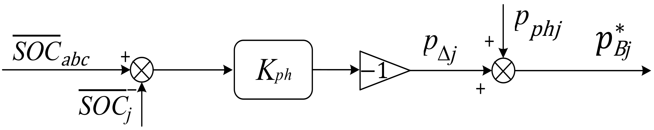
3.1. Phase-Leg Balancing

Influenced by different operation modes, the total battery power demand P B * is determined by the DC-link power P DC * and the AC grid power P AC * . The relationship between these three power demands is as follows:
P B * = P A C * P D C *
P B * is distributed to all battery packs. The basic power demand of each battery pack P Bav is given by the following equation:
P B a v = P B * n S M
where nSM is the number of the submodules in the system (6N in the normal operation).
The total power reference of the phase leg P B j * , as shown in Figure 3, is obtained by combining the difference regulated by proportional controller of the average of phase leg S O C ¯ a b c and the average of all battery packs’ SOC in the same phase leg S O C ¯ j with the adjustment power based on capacity.
p B j * = p p h j + p Δ j
where p p h j is the power regulations based on battery capacity proportion of three-phase legs
p p h j = i = 1 N ( C j u i + C j d i ) 1 3 i = 1 N ( C A u i + C B u i + C C u i + C A d i + C B d i + C C d i ) 2 N P B a v  
p Δ j is generated via the P controller by
p Δ j = K p h ( S O C ¯ a b c S O C ¯ j )
According to reference power of each phase, DC circulating can be deduced,
i D C j * = ( p B j * P A C * / 3 ) U D C
The circulating of each phase leg iZj can be obtained by adding upper arm current and lower arm within the same phase leg, as shown in Figure 4. The DC circulating current iDCj of each leg is obtained through a low-pass filter whose cut-off frequency is less than 50 Hz, and a PI controller is employed to track iDCj, and achieving SOC balance of the phase leg.

3.2. Upper and Lower Arm Balancing

As shown in Equation (5), the AC circulating current IXj can convert the power p Δ armjud between the upper and lower arms. The deviation in the power reference is obtained through proportional control for the SOC difference of the upper and lower arms and the different of power reference based on arm capacity, as follows:
p Δ a r m j u d * = K a r m ( S O C ¯ j u S O C ¯ j d ) + 1 2 ( p a r m j u p a r m j d ) = p Δ j u d + 1 2 ( p a r m j u p a r m j d )
The deviation between p armju and p armjd is power reference based on battery capacity deviation between upper and lower’s arm, the power transfer from upper and lower arm based on capacity is calculated as follow,
p a r m j u p a r m j d = ( n = 1 N C j u i 1 2 n = 1 N ( C j u i + C j d i ) n = 1 N C j d i 1 2 n = 1 N ( C j u i + C j d i ) ) N p Bav  
To prevent from DC-grid current distortion caused by SOC balancing control, the three-phase AC circulating currents should only be composed of positive and negative sequence components, as shown in Figure 5. The calculating method is described in detail in [20], and the magnitude and phase angle of the positive and negative sequence currents are derived from the given power to be shifted between the upper and lower arms. As shown in the lower part in Figure 4, a proportional resonant (PR) controller is employed to adjust IXj.
Equations (14) and (16) show that the SOC balancing rate is determined by the proportional coefficients Kph and Karm. However, the value of these coefficients has to be limited in case of over-modulation.

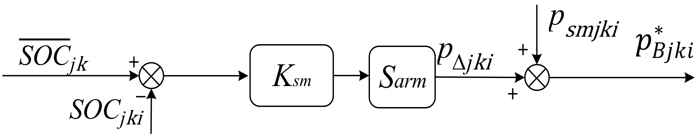
3.3. Submodule Balancing

The objective of the former two SOC balancing control methods is to generate equal average SOC of each arm. The SOC balancing of the submodules within an arm is implemented by adjusting the given power of each submodule p Bjki * is shown in Figure 6, as follows:
The variable Sarm is the power regulating direction. Since battery packs within an arm have the same current direction, the value of Sarm is −1 when the total arm battery power p Bjki * is less than zero. Namely, the batteries are in charge and the value of Sarm turns to 1 when p Bjki * is greater than zero.
p B j k i * = P s m j k i + p Δ j k i
where p Δ jki is generated by a proportional controller as follows:
p Δ j k i = S a r m K s m ( S O C ¯ j k S O C ¯ j k i )
p smjkii is power regulations based on battery capacity coefficient of submodule within the same arm.
p s m j i = C j u i 1 N n = 1 N C j u i N p B a v
By multiplying ki with the arm voltage reference u j k * , the total arm active power of each submodule can be obtained.
The power ratio factor ki is calculated as
k i = p B j k i * i = 1 N p B j k i *
Similarly, the coefficients need to be limited for avoiding over-modulation. Ignoring the voltage drop in the arm inductors and grid inductors, the limitation of ki can be written as
K s m ( U B n o r   m U B min C max C a v r ) P B a v Δ S O C max
where ΔSOCmax is the maximal SOC difference among the SOCs of the battery packs and the corresponding average arm SOC, uBmin is the minimum battery pack voltage. m is rated modulation ratio, Cavr and Cmax is average capacity and maximum capacity within an arm.
In this paper, the direct current control based on the dq axis is employed to control the AC grid’s current. The general control structure of the MMC-BESS is shown in Figure 7.

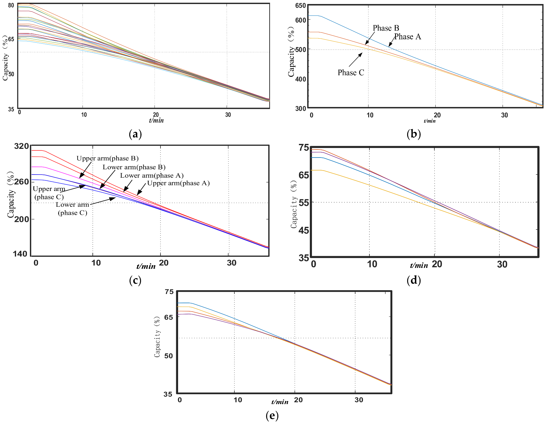
4. Simulation Results

To demonstrate the feasibility of the proposed SOC balancing control strategy under both normal operation and fault-tolerant operation, a simulation model based on the topology shown in Figure 1 was built in MATLAB/Simulink. Table 1 summarizes the parameters of the simulation model. The initial SOC values of the 24 battery modules are randomly set from 80.0% to 83.0%, and various capacity is preset as listed in Table 2.
First of all, only three-level SOC balance is implemented, the DC link absorbs energy from the system and its reference power is kept at −37.5 kW. The AC grid conveys 93.3 kW to the system for 240 s. So, the battery is charged during this time. Then, adding the power regulation based on capacity proportion in the second time simulation, to verify the method proposed in this paper. The power configuration is the same as the first time. Finally, changing the AC power from 93.3 kW to −64.65 kW to test the strategy when the batteries are discharged.
Figure 8 and Figure 9 reveal that the control strategy proposed in the paper have less influence on the AC output current and DC-link current. The global and local zoomed-in waveforms of the circulating currents are illustrated in Figure 10. It shows that the SOC balancing control generates a large circulating current at the begin of simulation for both 3-level SOC balance control and power adjustment based on capacity is working, then the circulating decrease gradually, finally it become stable. At the end of simulation, power adjustment based on capacity play great role in the circulating and adjustment from 3-level SOC balance control is little.
Figure 11 illustrates the simulation results of the 3-level SOC balancing control without power adjustment in charge mode. Figure 12 illustrates the simulation results of the 3-level SOC balancing control combined with power adjustment based on capacity in charge mode. Figure 13 reveals the simulation results of the 3-level SOC balancing control combined with power adjustment based on capacity in discharge mode.
In Figure 11, only the three-level SOC balance control strategy is implemented. The Figure 11a shows that the SOC of all battery almost converge at last, however, the convergence is poor for the batteries with various capacity. The maximum SOC difference of all battery reduce to 0.6%. Besides, in Figure 11b, the SOC difference of three-phase leg reduced from 0.45% to 0.2%. It is more obvious that the capacity has influence the SOC balance. In Figure 11c,d, the SOC difference of upper and lower arm is less than 0.001% in phase A with same capacity, but it is 0.4% in phase B with various capacity.
In Figure 12, power adjustment based on capacity is added to the simulation and the convergence of SOC gets better contrast with Figure 11. The maximum different SOC of all battery becomes 0.1% at last, and the different SOC of the three-phase leg is reduced to less than 0.01% in Figure 12b. The deviation of upper and lower arm has decreased to 0.05% in Figure 12d. The maximum SOC difference in the upper arm of phase B has also reduced, which is 0.05% less than 0.18% showed in Figure 11f. The obvious contrast of Figure 11 and Figure 12 reveal that the three-level SOC balance control combine with power regulation related to capacity can balance the batteries with different capacity. Finally, the three-level SOC balancing and power adjustment based on capacity in discharge mode is simulated in Figure 13.

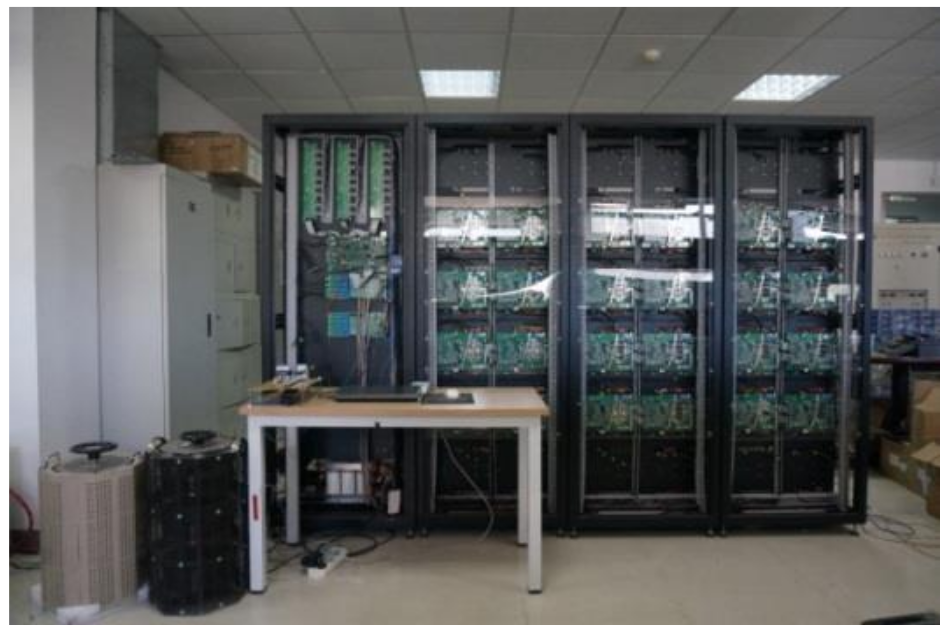
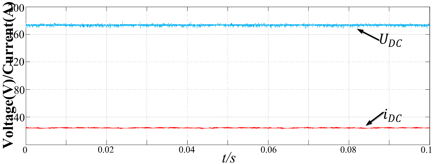
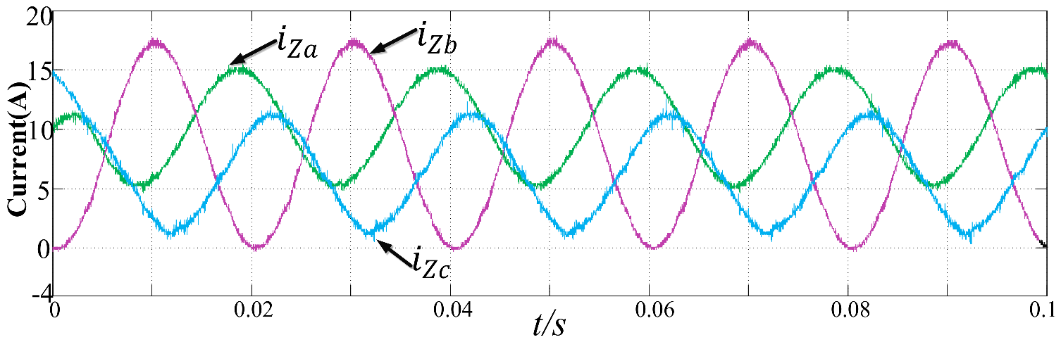
5. Experimental Results

To verify the effectiveness of the proposed control strategy, a prototype was built in the lab as shown in Figure 14. The parameters of the experimental system are shown in Table 3. Due to the large number of submodules, a digital signal processor (DSP) and a field-programmable gate array (FPGA) are employed in this prototype. Since the foundation of the SOC balancing control strategy is the individual battery power control, this paper firstly validates the feasibility of the internal power flow control, then verifies the three-level SOC balance control strategy of MMC-BESS.
Figure 15 and Figure 16 show the waveforms of the grid current and the DC-link voltage and current. Figure 17 shows the output voltages of the converter, which has nine levels. Figure 18 illustrates the currents of the 9 battery submodules (au, ad, bu, bd, cu1, cu2, cu3, cu4, and cd). The average value of the battery current is analyzed by the scope and marked on the image. It can be seen that the average current of the battery submodules in phase a, b, and c decrease in turn and that the average current of the upper arm is greater than the lower arm in phase b. Meanwhile, the battery currents of the submodules within the upper arm of phase c decrease with an equal difference.
Figure 19 illustrates the waveforms of three-phase circulating currents, which contain the DC and AC circulating components. These waveforms are measured at the same time in Figure 17. By comparing the phase angle of the converter output voltages and circulating currents of each phase, 90° and −90° is discovered in phase A and phase C, respectively. In this case, the AC circulating currents do not transfer power between the arms within the same phase leg. However, the circulating current in phase B has the opposite phase angle compared with the converter output voltage and thus, the circulating current transfers substantial active power from the lower arm to the upper arm of phase B. Since the total battery power reference of each phase leg has decreased from phase A to phase C, the DC components of the circulating currents decrease correspondingly.
If the power of the DC link is greater than the AC side, the batteries will be charged, and vice versa. Since each battery module has an individual reference power, the total battery reference power of each phase and each arm will be different.
Figure 20 shows the experimental results of the SOC balancing control of the three-level MMC-BESS. Owing to the limitation of experimental conditions, the battery module capacity is basically the same, the results under various batteries capacities has been verified in the previous simulation. Figure 20a shows the SOC of all the battery modules in the system. The SOC difference of the battery decreases from 15.64% (at the beginning state) to 1.67% (after 40 min), which verifies the effectiveness of the proposed balancing strategy. Figure 20b,c represent the trend of the three-phase SOC and the bridge arm SOC, respectively. In a certain period, the three-phase and bridge arm SOC also tend to be consistent. The Coulomb integral method was used in this strategy for SOC estimation due to some inevitable error existing in the current sampling. However, there is still a little deviation in the SOC estimation, which will affect the SOC convergence results at the end of the equilibrium process. However, this experiment generally conforms to the theoretical expectation and verifies the correctness of the theory.

6. Conclusions

This paper focuses on the second-life battery used in MMC-BESS, and presents the shortcomings of both SOC and capacity inconsistency. The internal power flow in the AC grid, battery and DC link is analyzed. The results show that the fundamental component of both DC and AC circulating current can be used to adjust the total battery power of phase legs and arms respectively, and the power of submodules can be changed by adjusting the submodule output voltage. Based on the above-mentioned results, a three-level SOC balance control strategy is proposed: adjusting the power related to the capacity ratio of three-phase leg; considering the difference of the upper and lower leg’s capacity, and the proportional capacity of the submodule collaborating on closed-loop control of the SOC to balance the SOC of MMC-BESS. Eventually, the batteries’ SOC balance in MMC-BESS is achieved. Finally, the effectiveness and feasibility of the proposed methods are verified by results obtained from simulations and the experimental platform.

Acknowledgments

This work is financially supported by National Natural Science Foundation of China under Key Program 61633015.

Author Contributions

In this paper, author contributions are as follows: Hui Liang, Long Guo and Junhong Song conceived and designed the experiments; Hui Liang, Long Guo and Yong Yang performed the experiments; Hui Liang analyzed the data; Junhong Song, Hongfeng Qi and Weige Zhang contributed reagents/materials/analysis tools; Hui Liang, Junhong Song and Long Guo wrote the paper.

Conflicts of Interest

The authors declare no conflicts of interest.

Abbreviations

The following abbreviations are used in this manuscript:
MMCModular Multilevel Converter
SOCState of Charge
BESSBattery Energy Storage System
HVDCHigh-voltage Direct Current
PWMPulse Width Modulation

References

  1. Neubauer, J.; Pesaran, A. The ability of battery second use strategies to impact plug-in electric vehicle prices and serve utility energy storage applications. J. Power Sources 2011, 196, 10351–10358. [Google Scholar] [CrossRef]
  2. Diao, W.; Jiang, J. Flexible Grouping for Enhanced Energy Utilization Efficiency in Battery Energy Storage Systems. Energies 2016, 9, 498. [Google Scholar] [CrossRef]
  3. Diao, W.; Xue, N. Active battery cell equalization based on residual available energy maximization. Applied Energy 2018, 15, 690–698. [Google Scholar] [CrossRef]
  4. Li, Q.; Liang, H. Modular Battery Energy Storage System Based on One Integrated Primary multi-Secondaries Transformer and its Independent Control Strategy. In Proceedings of the IEEE Transportation Electrification Conference and Expo, (ITEC Asia-Pacific), Harbin, China, 7–10 August 2017. [Google Scholar]
  5. Song, J.; Zhang, W. Fault-Tolerant Control for a Flexible Group Battery Energy Storage System Based on Cascaded Multilevel Converters. Energies 2018, 11, 171. [Google Scholar] [CrossRef]
  6. Maharjan, L.; Yamagishi, T. Active-Power Control of Individual Converter Cells for a Battery Energy Storage System Based on a Multilevel Cascade PWM Converter. IEEE Trans. Power Electron. 2012, 27, 1099–1107. [Google Scholar] [CrossRef]
  7. Mehrasa, M.; Pouresmaeil, E.; Zabihi, S.; Vechiu, I.; Catalão, J.P. A multi-loop control technique for the stable operation of modular multilevel converters in HVDC transmission systems. Int. J. Electr. Power Energy Syst. 2018, 96, 194–207. [Google Scholar] [CrossRef]
  8. Mehrasa, M.; Pouresmaeil, E.; Taheri, S.; Vechiu, I.; Catalão, J.P. Novel Control Strategy for Modular Multilevel Converters Based on Differential Flatness Theory. IEEE J. Emerg. Sel. Top. Power Electron. 2017, 99, 1–11. [Google Scholar] [CrossRef]
  9. Mei, J.; Xiao, B.; Shen, K.; Tolbert, L.M.; Zheng, J.Y. Modular Multilevel Inverter with New Modulation Method and Its Application to Photovoltaic Grid-Connected Generator. IEEE Trans. Power Electron. 2013, 28, 5063–5073. [Google Scholar] [CrossRef]
  10. Meshram, P.M.; Borghate, V.B. A Simplified Nearest Level Control (NLC) (NLC) Voltage Balancing Method for Modular Multilevel Converter (MMC). IEEE Trans. Power Electron. 2015, 30, 450–462. [Google Scholar] [CrossRef]
  11. Vasiladiotis, M.; Rufer, A. Analysis and Control of Modular Multilevel Converters With Integrated Battery Energy Storage. IEEE Trans. Power Electron. 2015, 30, 163–175. [Google Scholar] [CrossRef]
  12. Quraan, M.; Yeo, T. Design and Control of Modular Multilevel Converters for Battery Electric Vehicles. IEEE Trans. Power Electron. 2015, 31, 507–517. [Google Scholar] [CrossRef]
  13. Zhang, L.; Gao, F. Interlinking modular multilevel converter of hybrid AC-DC distribution system with integrated battery energy storage. In Proceedings of the Energy Conversion Congress and Exposition, Montreal, QC, Canada, 20–24 September 2015; pp. 70–77. [Google Scholar]
  14. Quraan, M.; Tricoli, P.; D’Arco, S.; Piegari, L. Efficiency Assessment of Modular Multilevel Converters for Battery Electric Vehicles. IEEE Trans. Power Electron. 2016, 32, 2041–2051. [Google Scholar] [CrossRef]
  15. Diao, W.; Jiang, J.; Zhang, C.; Liang, H. Energy state of health estimation for battery packs based on the degradation and inconsistency. Energy Procedia 2017, 142, 6581–6591. [Google Scholar] [CrossRef]
  16. Hillers, A.; Biela, J. Fault-tolerant operation of the modular multilevel converter in an energy storage system based on split batteries. In Proceedings of the European Conference on Power Electronics and Applications, Lappeenranta, Finland, 26–28 August 2014; pp. 1–8. [Google Scholar]
  17. Chen, Q.; Li, R. Analysis and Fault Control of Hybrid Modular Multilevel Converter with Integrated Battery Energy Storage System. IEEE J. Emrg. Sel. Top. Power Electron. 2017, 5, 64–79. [Google Scholar] [CrossRef]
  18. Ma, Y.J.; Lin, H.; Wang, Z.; Wang, T. Capacitor voltage balancing control of modular multilevel converters with energy storage system by using carrier phase-shifted modulation. In Proceedings of the IEEE Applied Power Electronics Conference and Exposition, Tampa, FL, USA, 26–30 March 2017; pp. 1821–1828. [Google Scholar]
  19. Tu, Q.; Xu, Z. Mechanism analysis on the circulating current in modular multilevel converter based HVDC. High Volt. Eng. 2010, 36, 547–552. (In Chinese) [Google Scholar]
  20. Soong, T.; Lehn, P. Internal Power Flow of a Modular Multilevel Converter with Distributed Energy Resources. Emerg. Sel. Top. Power Electron. IEEE J. 2014, 2, 1127–1138. [Google Scholar] [CrossRef]
Figure 1. The configuration of the MMC-BESS and its submodule.
Energies 11 00873 g001
Figure 2. A diagram of the carrier phase-shift modulation (7 levels).
Energies 11 00873 g002
Figure 3. The phase-leg SOC balancing controller.
Energies 11 00873 g003
Figure 4. Block diagram for circulating current control.
Energies 11 00873 g004
Figure 5. The upper and lower arms SOC balancing controller.
Energies 11 00873 g005
Figure 6. The individual submodule SOC balancing controller.
Energies 11 00873 g006
Figure 7. The general control structure of the MMC-BESS.
Energies 11 00873 g007
Figure 8. The AC grid output currents.
Energies 11 00873 g008
Figure 9. The DC-link current.
Energies 11 00873 g009
Figure 10. The circulating currents of the three-phase legs.
Energies 11 00873 g010
Figure 11. Three-level SOC balancing without power adjustment in charge mode. (a) The SOC of all 24 battery modules. (b) The SOC balancing among the three phase legs. (c) The SOC of upper and lower arm within phase A. (d) The SOC of upper and lower arm within phase B. (e) Submodule SOC of upper arm in phase A. (f) Submodule SOC of upper arm in phase B.
Energies 11 00873 g011
Figure 12. Three-level SOC balancing with power adjustment based on capacity in charge mode. (a) The SOC of all 24 battery modules. (b) The SOC balancing among the three phase legs. (c) The SOC of upper and lower arm in phase A. (d) The SOC of upper and lower arm in phase B. (e) Submodule SOC of upper arm in phase A. (f) Submodule SOC of upper arm in phase B.
Energies 11 00873 g012aEnergies 11 00873 g012b
Figure 13. Three-level SOC balancing and power adjustment based on capacity in discharge mode.
Energies 11 00873 g013
Figure 14. The prototype system.
Energies 11 00873 g014
Figure 15. The experiment result of the AC output current.
Energies 11 00873 g015
Figure 16. The waveforms of the DC-link voltage and current.
Energies 11 00873 g016
Figure 17. The waveforms of the converter output voltages.
Energies 11 00873 g017
Figure 18. The currents of the battery modules.
Energies 11 00873 g018
Figure 19. The waveforms of the three-phase circulating currents.
Energies 11 00873 g019
Figure 20. The experimental results of the three-level SOC balancing. (a) The SOC balancing of each module. (b) The interphase SOC balancing. (c) The intra-phase SOC balancing. (d) The SOC balancing of the upper arm of phase B. (e) The SOC balancing of the lower arm of phase B.
Energies 11 00873 g020
Table 1. The parameters of the simulation system.
ItemValue
Output voltage (phase, peak) u ^ g 311 V
DC-link voltage u DC 750 V
Arm inductance L 1 mH
Submodules in one armN4
Equivalent series resistanceR0.1 Ω
Grid inductanceLg1.5 mH
Submodule capacitance C 0 2200 μ F
Nominal battery voltage u B 250 V
Nominal battery capacity C B 10 Ah
Switching Frequency f w 5000 Hz
Table 2. The initial SOCs and capacity of the 24 battery modules.
PhaseArmSubmodules SOC and Capacity(Ah)Mean SOC/Capacity(Ah)Mean SOC/Capacity(Ah)
1234
au80.7%/880.3%/882.9%/881.4%/881.325%/880.975%/8
d80.1%/881.2%/880.7%/880.5%/880.625%/8
bu82.7%/1080.0%/1180.2%/1381.6%/1481.125%/1281.388%/10
d80.8%/881.2%/882.6%/882.0%/881.65%/8
cu81.8%/1083.0%/1082.2%/1081.9%/1082.225%/1081.763%/12
d81.8%/1481.1%/1480.8%/1481.5%/1481.3%/14
Table 3. The parameters of the experimental system.
ItemValue
Output voltage (phase, peak) u ^ g 65 V
DC-link voltage u DC 180 V
Arm inductance L 1 mH
Grid inductanceLg0.6 mH
Submodule capacitance C 0 2200 μ F
Nominal battery voltage u B 45 V
Switching Frequency f w 5000 Hz
Battery Pack Capacity6 AH
Battery Typeternary lithium battery
Battery Pack Grouping Method12 series 2 parallel
Rated Battery Pack Voltage44 V

