Article

Hybrid Communication Architectures for Distributed Smart Grid Applications

1
National Renewable Energy Laboratory (NREL), Golden, CO 80401, USA
2
Department of Electrical and Computer Engineering, University of Colorado, Boulder, CO 80309, USA
3
Department of Electrical and Computer Engineering, The University of Akron, Akron, OH 44325, USA
*
Author to whom correspondence should be addressed.
Energies 2018, 11(4), 871; https://doi.org/10.3390/en11040871
Submission received: 9 March 2018 / Revised: 2 April 2018 / Accepted: 4 April 2018 / Published: 9 April 2018
(This article belongs to the Section F: Electrical Engineering)

Abstract

:
Wired and wireless communications both play an important role in the blend of communications technologies necessary to enable future smart grid communications. Hybrid networks exploit independent mediums to extend network coverage and improve performance. However, whereas individual technologies have been applied in simulation networks, as far as we know there is only limited attention that has been paid to the development of a suite of hybrid communication simulation models for the communications system design. Hybrid simulation models are needed to capture the mixed communication technologies and IP address mechanisms in one simulation. To close this gap, we have developed a suite of hybrid communication system simulation models to validate the critical system design criteria for a distributed solar Photovoltaic (PV) communications system, including a single trip latency of 300 ms, throughput of 9.6 Kbps, and packet loss rate of 1%. The results show that three low-power wireless personal area network (LoWPAN)-based hybrid architectures can satisfy three performance metrics that are critical for distributed energy resource communications.

1. Introduction

The increasing penetration of distributed Renewable Energy Sources (RESs) and Energy Storage Systems (ESSs), including storage batteries and electrical vehicles, brings new challenges. It also requires the evolution of the electricity distribution grids to enable their full utilization and effective automation [1]. With distributed RESs providing an increasing proportion of total generation and ESSs providing both high power density and high energy density to accommodate the uncertainty of RESs, they must take on more responsibilities to ensure continued reliable and cost-effective distribution grid operations [2,3,4]. These include providing voltage and reactive power support to aid local distribution system operations, providing aggregated ancillary services to the bulk power system, as well as shifting load from peak to off-peak and flattening the peak electricity demand. Therefore, the monitoring and further control of these leading and emerging RESs and ESSs are progressively pervading modern distribution networks. To achieve these goals, the communication infrastructure is required to allow for bidirectional information exchange between distributed generation and storage elements and various levels of the smart grid.
The envisioned underlying communication network for the smart grid applications broadly consists of Home Area Networks (HAN), Neighborhood Area Networks (NAN), and a Wide Area Network (WAN) in a multi-layer fashion. It is expected that a variety of communications technologies will be utilized in the hybrid communications systems infrastructure. Many studies have been dedicated to communication network architectures to coordinate distributed components, especially renewable generation, in smart grids. Much of the work performed to date has focused on high-level service and technology requirements and design principles with little attention to practical design and implementation challenges [5,6,7,8]. Although useful insights have been provided in these studies, the existing results cannot be directly extended and applied to practical smart grid communications system design and deployment for the coordination of high-penetration distributed RESs and storage devices.
Hybrid network architectures using both wireless and dedicated wired media have been proposed and studied as a promising solution to smart grid communication infrastructures due to the balanced tradeoff between investments and benefits, and meeting the critical requirements of the smart grid applications. Specific hybrid communication architectures, such as Power Line Communication (PLC) and WiFi, were developed and evaluated in the experimental pilot smart grid cities [9,10,11]. These research results provide limited perspectives of the specific hybrid communications implementations for the particular smart grid topologies without considering the design framework and toolbox development. Although hybrid communication architectures are proposed in [12,13], the authors evaluate the performance by using the single technology simulation networks. Furthermore, the interworking IP address issue between IEEE 802.11s-based mesh network of the NAN and Long-Term Evolution (LTE) network of the WAN is addressed by the privacy-aware communication protocol-based gateway in [14]. The proposed mechanism is implemented in the particular IEEE 802.11s and LTE-based hybrid simulation with the Network Simulator 3 (NS3) network simulator. However, little attention has been paid to the development of a suite of hybrid communication architecture simulation models to verify the critical system design criteria.
To this end, a suite of hybrid communication system simulation models using the discrete-event NS3 is developed for distributed smart grid applications. The NS3 library was chosen because of its popularity and the existing availability of models for numerous networking functionalities. The envisioned communication network comprises HANs, NANs, and a WAN, as shown in Figure 1. Note that the PV panel represents the distributed RESs and storage devices in the rest of paper. In a HAN, the PV panel is connected to a smart meter through two alternative communication technologies: low-power wireless personal area networks (LoWPAN) and power line communication (PLC). Broadband PLC (BPLC) is a method of PLC that allows relatively high-speed digital transmission over the public electric power distribution wiring. In addition, it uses higher frequencies and a wider frequency range, which result in a higher data rate for shorter range applications. Also, Narrowband PLC (NPLC) refers to low bandwidth communication, utilizing the frequency band below 500 kHz and providing data rates of tens of kbps. In addition, it is suitable for smart home/building automation. Thus, both BPLC and NPLC can be applied in a HAN. Within an NAN, the data transmitted from the smart meter to the data concentrator, eventually arrives at the wide area network (WAN) through the WAN edge router via Ethernet cable, WiFi, or WiMAX. To fully examine the combinations of these five technologies, we consider six possible hybrid architectures and develop six corresponding hybrid prototype simulation models. The main challenge of developing NS3-based hybrid communication simulation models is integrating different communication technologies and IP address mechanisms into one simulation network because it is an open-source, still in the developing routine. To address this, a NetRouter forwarding function is specifically designed in the application level. To the best of our knowledge, it is the first time hybrid communication simulation models have been created to validate the effectiveness and scalability of hybrid architecture design for distributed smart grid applications.
Note that we have identified the missing research about hybrid communications architecture design for distributed smart grid applications previously. Problem one is the development of a suite of hybrid simulation models, which is addressed in this paper. Problem two is the design framework of hybrid communications architecture for coordinate distributed RESs and ESSs, which will be our future work.
The rest of this paper is organized as follows. Section 2 provides an overview of the smart grid communication network. Then Section 3 discuss the development of six NS3-based prototypical hybrid communication system simulation models. Verification of the developed hybrid simulation models and further validation of the design criteria of each hybrid architecture on top of the Reference Test Case-A (RTC-A) power system is presented in Section 4. Finally, conclusions are drawn and future work is discussed in Section 5.

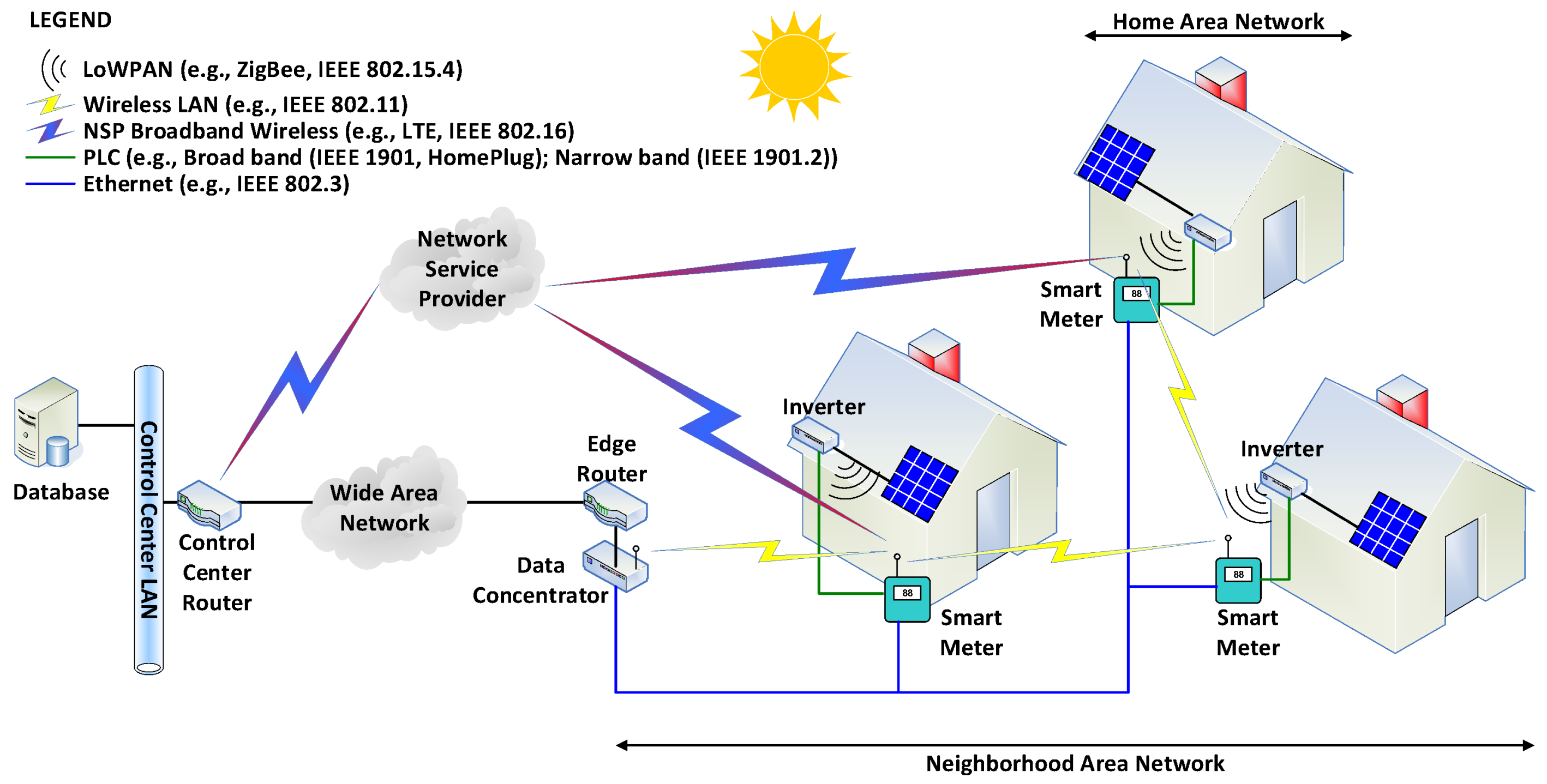
2. Communication Network Architecture and Design Criteria for the Smart Grid

In modern power systems, the utility communications system are designed and deployed in the form of a core-edge networks [15]. By doing so, a WAN, usually based on fiber optics, forms the backbone of the system; whereas the connections between end devices and the WAN are established via NANs. At the edge of this network, the end devices, including home appliances, batteries, renewable generators, and smart meters, form the HAN as the envisioned communication systems of a smart grid, as shown in Figure 1. It is not common for an individual end device in an HAN to be directly connected to the control center local area network. Therefore, all connections from end devices to control centers at different portions of the power grid must eventually go through the existing well-developed WAN that either dedicated or public. As such, our focus is narrowed to the communication network that enables data transmission between the PV panels and the first WAN edge router. This communication network has a hierarchical structure that consists of:
  • A HAN that connects the PV panel to the smart meter located at the customer house serving as the gateway to the utility’s network. The geographical size of a HAN can be up to a few tens of meters. In the smart grid, prosumers want advanced applications such as consuming electricity at low prices and selling electricity at high prices, which requires an effective and reliable HAN.
  • An NAN that collects the data from multiple smart meters and transmits it to the WAN through a WAN edge router. The geographical size of an NAN depends on multiple factors that mainly include the distribution system topology and distributed smart grid applications. It can range from hundreds of meters to several kilometers.
To enable data transmission between the individual PV panels and the WAN edge router, the envisioned communication network comprises three major data flows: (1) PV inverter—smart meter (2) Smart meter—data concentrator; and (3) Data concentrator—edge router. There are various communication protocols and technologies that can be used for data communication in power systems [6,16,17]. The proper technologies for each data link have been investigated and chosen based on the level of maturity of the technology, such as whether it is open source and nonproprietary, and whether it offers a sufficient data rate. Two primary alternative communication technologies are available between PV inverters and the smart meters in a HAN: Zigbee/LoWPAN and PLC. The communication between smart meters and data concentrators can be conducted via Ethernet cable, WiFi, and WiMAX. The LoWPAN is chosen instead of the well-known ZigBee (both of them are based on IEEE 802.15.4), because there is no official Zigbee module in NS3.
The distributed smart grid concept proposed by Advanced Research Institute of Virginia Tech [18,19] means to reliably and effectively coordinate the distributed RESs and ESSs, as well as controllable loads from demand respond point of view at a distribution grid which is covered by multiple HANs and an NAN. Following this concept, the emerging distributed applications for the Distribution System Operator (DSO) within an NAN can be categorized into the following three groups: (1) distributed distribution system state estimation and control strategies only at the NAN level, such as coordinated voltage control [20], distributed optimal dispatch of distributed RESs [21]; (2) distributed monitoring and control of customer-owned RESs and ESSs through both a NAN and multiple HANs; (3) while within a HAN, instead of the traditional demand-driven-supply approach, the supply-driven-demand mechanism must be implemented in a distributed way to allow an interactive matching of flexible load and available generation at a “correct” price by the ways such as the local power sharing, priority-based load curtailment and demand response [19]. Considering the totally different data rates (1–100 Kbps for HAN, 100 Kbps–10 Mbps for NAN) and coverage range requirements (1–100 m for HAN, 100 m–10 km for NAN) at a HAN and an NAN [6], it indicates that studying hybrid communications architectures is so important to accommodate the above distrinct distributed applications at different area networks. In addition, the use of hybrid communications architectures is interesting in that the possibility of implantation of redundant structure, namely the same information is sent over two or more different communication media, increases reliability [11]. Furthermore, the comprehensive study of the hybrid communications network will help identifying the vulnerable paths, which can be bypassed through middleware-based approach [22] in establishing communication among the end-users and DSOs.
The expected communication architecture should provide utilities with visibility into and control over distributed PV generation, and they will be designed based on three criteria. (I) Feasibility: it enables different protocol standards and IP address mechanism used within each network without causing interoperability issues; (II) Scalability: it emphasizes the accommodation of not only the PV data flow from distributed PV generation, but also power system state measurement data from the large-scale transmission-distribution power systems; (III) Reliability: it refers to three performance metrics of (1) latency–the expected one-way latency for distributed PV control and monitoring at the distribution grid is in the range from 300 ms–2 s; (2) throughput–the requirement for the distributed PV is 9.6–56 Kbps; (3) packet loss rate; its benchmark value for distributed RES applications is set to 0.01–1% [23,24].
The ultimate objective is to design an appropriate hybrid communications architecture for the coordination of distributed RESs and ESSs with emphasis on using open-source and standardized protocols and the existing communication infrastructure as much as possible. To this end, this paper focuses on simulating hybrid communication architectures to verify the critical system design criteria especially for distributed smart grid applications.

3. Hybrid Communication Simulation Models

In this section, we focus on the development of the software simulation models that represent the envisioned hybrid communications system to test and verify the critical system design criteria introduced in the previous section, including feasibility, scalability, and reliability. Among different widely used network simulators, NS3 is selected because it is popular, open source, and has modules for numerous networking functionalities [25,26,27,28]. With the combination of all five alternative communication technologies for both HAN and NAN described in Section 2, six possible such hybrid communication architectures, shown in Table 1, are considered. Next, the development of prototypical hybrid simulation models in NS3 for each hybrid architecture will be described in detail.
The main challenge of developing NS3-based hybrid communication simulation models is to integrate different communication technologies and IP address mechanisms into one simulation network. To address this, we start with the development of prototypical hybrid simulation models for each proposed hybrid architecture to validate the primary hybrid system design criteria of feasibility.
For the sake of simplicity, a prototypical model consists of one PV inverter, one smart meter, and one data concentrator along with the point-to-point (P2P) topology. The PV data generated at the PV inverter is sent to the smart meter through LoWPAN/PLC, and the smart meter relays the packet to the data concentrator through WiFi/WiMAX/Ethernet, which are shown as two black double-arrowed lines on the bottom of Figure 2. Based on this P2P topology, the schematic in Figure 2 also presents the components of the network Open Systems Interconnection model in each communication node: physical layer, Medium Access Control (MAC) layer of the data link layer, network layer, transport layer, and application layer. Different communication technologies are mainly characterized according to the electrical and physical transmission medium of the physical layer and medium access control strategies of the MAC layer. These two bottom layers, which are shown grouped into one white box in Figure 2, will be described in terms of protocols and communication nodes, followed by the network layer, transport layer, and application layer, respectively.

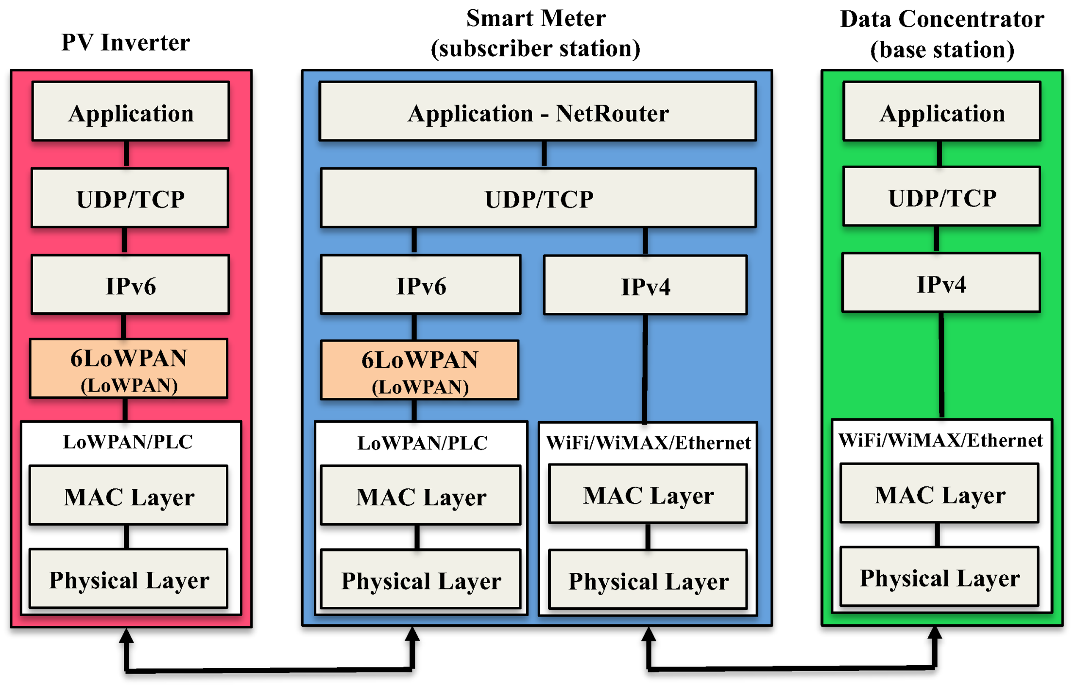
3.1. Physical- and MAC-Layer Attributes

In the PV inverter node of Hybrid 1 through Hybrid 3, the low-rate wireless personal area network (LR-WPAN) module in NS3 is employed to implement LoWPAN as specified by IEEE standard 802.15.4. Its physical layer consists of a physical model, an error rate model, and a loss model. Its MAC layer implements the un-slotted carrier-sense multiple access with collision avoidance (CSMA/CA) variant without beaconing. Note that IEEE 802.15.4 only specifies the physical layer and media access control, and it cannot make the IP packet run via the LoWPAN network. Therefore, in the NS3 simulator, the 6LoWPAN module along with transmission of IPv6 packets via IEEE 802.15.4 networks has been employed as an agent between the bottom two layers and the network layer, shown in the orange block of Figure 2. It plays a critical role enabling IEEE 802.15.4 to cooperate with other protocols.
The PLC module developed by researchers at the University of British Columbia is used to implement the PLC technology in the PV inverter node of Hybrid 4 through Hybrid 6 [26]. It is an NS3-based implementation to simulate the signal propagation in PLC. It is necessary to predefine certain physical- and MAC-layer attributes for specifying the particular PLC technology adopted in our work. The attributes include spectrum model, transmit power spectral density, cable types, background noise, channel, and outlets. These configurable attributes also make the simulation of realistic PLC networks more precise by tuning them.
As a relay, the smart meter node is required to configure two sets of software net devices for both the MAC and physical layers to accommodate two communication technologies simultaneously. As shown in the smart meter block in Figure 2, the two lower layers in the left white box are used to communicate with the PV inverter node through the LoWPAN or PLC protocol, and those in the right white box are used to connect with the data concentrator node through the WiFi, WiMAX, or Ethernet protocol. To enable data transfer between these two software net devices, the Forwarding function in the IPv6 model has to be used in all six hybrid models.
In the data concentrator node, three optional protocols are implemented individually. Both WiFi and mesh modules are used to implement the mesh WiFi network. The mesh networking capabilities of the WiFi network is extended by using the mesh module according to the IEEE 802.11s standard [29]. To simulate the more precise real network and further achieve the optimal performance of the proposed network, they provide the configurable parameters including wifiPhy mode, wifiChannel, StackInstaller, SpreadInterfaceChannels, and MacType. In the WiMAX subnetwork, the smart meter is configured as a subscriber station and the data concentrator is set as a base station in cases Hybrid 3 and Hybrid 6. Among four scheduling services defined by the IEEE 802.16 standard, Unsolicited Grant Service (UGS) is chosen because it allows for low latency and low jitter in the proposed hybrid communication network [28]. Finally, the Ethernet cable technology is implemented through the basic CSMA module by setting channel attributes of data rate and delay.

3.2. Network Layer: IPv6 to IPv4

As previously mentioned, there is one challenge in simulating the hybrid communication networking infrastructure by using NS3 simulator. The LR-WPAN network in NS3 implemented by both LR-WPAN and 6LoWPAN modules supports only the IPv6 in the network layer. However, both the mesh WiFi and WiMAX networks only support the IPv4 in the current version of the NS3 simulator. To address this challenge, a NetRouter forwarding function is developed in the application layer, as illustrated in the smart meter node of Figure 2. This forwarding function is designed to decapsulate and encapsulate the IPv6 and IPv4 packets of the application layer and to realize the successful integration of the IPv6 and IPv4 networks.

3.3. Transport and Customized Application Layers

At the transport layer, both UDP and TCP protocols can be implemented in all three types of nodes. To accommodate the specific distributed PV coordination application, a customized Client module is developed to mimic the real PV data packet by setting the packet size and sending rate at the application layer. Furthermore, the scalability and modularity of the hybrid communication system simulation models is further improved by designing a Server module responsible for autonomous online tracing and data post-processing–namely, statistically collecting the network performance metrics, such as latency, packet loss rate, and throughput. The hybrid communications system design metrics can be gained based on these network metrics of each data flow. To achieve this objective, a Quality of Service (QoS) header is added at the application layer. This header is capable of carrying the information of the client identification and sending a time stamp. The client identification is used to identify the data flow; and the time stamp with resolution to a nanosecond is used to track the QoS information, such as latency and throughput. These features enable the implementation of the opportunistic routing strategy in the developed hybrid communication simulation models [22].

4. Verification and Validation Results

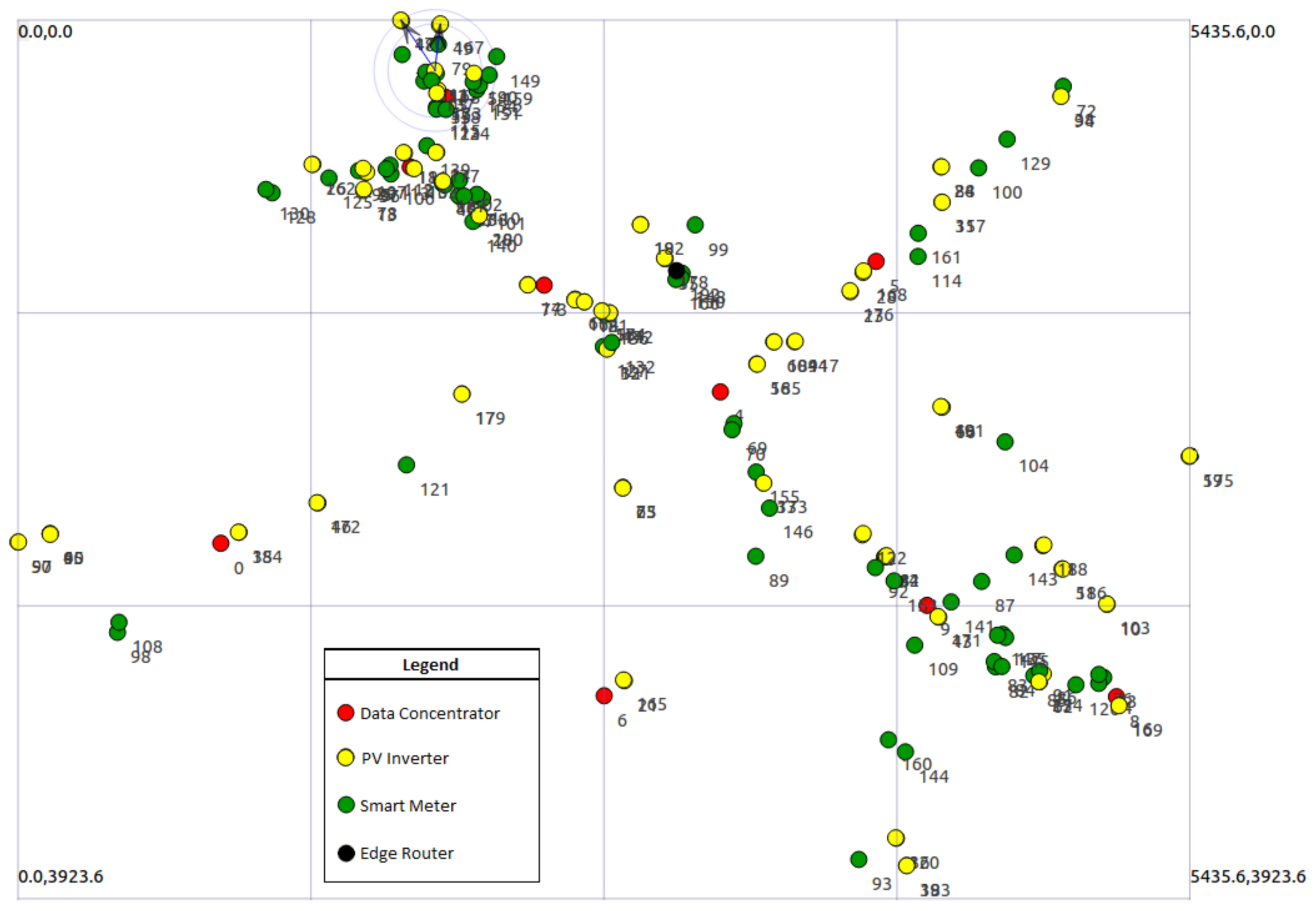
4.1. Reference Test Case A

The taxonomy feeder titled R2-25.00-1 with 1080 nodes, referred to as Reference Test Case A (RTC-A), has been selected to perform the validation of the developed six prototypical hybrid simulation models [30]. Distributed solar with a penetration of 5% is modeled on this feeder. The location and availability of communications infrastructure is modeled using data from the specific utility district service territory, which has rolled out smart metering across their utility network and uses the dedicated networks for data communication infrastructure. Typical smart meter installation rates and placement of data concentrators that have been built for current smart meter communication requirements are scaled to the R2-25.00-1 feeder. Therefore, the modification stated above, the subsequent communication infrastructure of RTC-A consists of 57 PV inverters, 275 smart meters, 10 data concentrators, and one edge router. As shown in Figure 3, the yellow dots represent inverters, both yellow and green dots denote as smart meters, the red dots indicate data concentrators, and the black dot illustrates the edge router. The RTC-A is divided into 10 subareas based on the location of 10 data concentrators.
Based on the six proceeding developed prototypical hybrid simulation models, we further developed a full NS3-based communication simulation test bed on top of RTC-A and validated the second primary hybrid system design criteria of scalability. In the implemented simulation test bed, the PV inverters communicate with smart meters via LoWPAN or PLC, and the smart meters communicate with the data concentrators via WiFi mesh, WiMAX, or Ethernet cable. The topology of RTC-A shows that each HAN usually consists of only 1 or 2 PV inverters and 1 smart meter, whereas each NAN consists of approximately 26 smart meters and 1 data concentrator. It indicates that each HAN has 1 or 2 PV-smart meter links without the scalability issue. As such, the focus is on the scalability challenge of smart meter-data concentrator links in the 10 NANs. In the case of Ethernet cable, the solution of scalability is straightforward by installing the declared CSMA module instance into a large amount of communication nodes, which does not work for either the case with WiFi mesh or the one with WiMAX. To address this challenge, the new WiFi/Mesh and WiMAX module instances must been declared for each subarea. In other words, multiple SpectrumChannel instances are used in the large-scale wireless networks simulation to avoid the WiFi co-channel interference in the physical (PHY) layer. Figure 3 shows the screen shot of the packet flow animation in the Hybrid 2 case of LoWPAN-WiFi.

4.2. Basic Configuration and Parameter Verification of Communication Models

In this subsection, we aim to identify the configurable parameters of NS3 modules of the five alternative communication technologies and to evaluate their impact on the performance of the proposed hybrid communication systems. We first consider two alternative communication technologies: LoWPAN implemented by the LR-WPAN and 6LoWPAN modules, and PLC implemented by the PLC module for the PV-Smart Meter link. The parameter verification results are demonstrated in Table 2, which lists all the adjustable parameters for each technology in the Parameter column. Note that alternative configurations for each adjustable parameter are listed in the Values column, and the first alternative setting is the optimal value based on our testing. The Impact column shows how parameters impact the network performance mainly based on latency. For the LoWPAN link, we identified two spectrum related adjustable parameters of propagation loss and delay using several existing simple models. Both have high impacts on the system performance in both the practice and the simulation because antenna and wave propagation mechanisms play vital roles in wireless communication networks. This also applies to the WiFi and WiMAX modules shown in Table 3.
Regarding PLC links, it is first verified that the BPLC with frequencies from 1.8–250 MHz has better performance than the NPLC with frequencies from 3–500 kHz for the HAN applications because of its suitability for shorter range applications with higher data rates; details will be discussed in the next subsection. Further, three observations on the impact of the module’s adjustable parameters are shown in Table 2. (1) Both the spectrum model and the payload modulation coding scheme play critical roles in the hybrid system performance. Two spectrum models are available for the PLC communication. Compared to the G3 spectrum model in NPLC, the time-invariant spectrum model performs better from the test. The configurable parameter setting of the spectrum model consists of low-bound frequency, high-bound frequency, and number of channels in which the channel number can mostly impact the system performance. Especially as it increases to more than 300, the lowest message latency and highest throughput can be achieved. Also, different payload modulation coding schemes show quite different system performance in terms of latency, throughput, and packet loss rate. In particular, the Quadrature Amplitude Modulation (QAM) modulation outperforms Binary Phase-Shift Keying (BPSK), the higher QAM modulation, the better the system performance, which is coincident with the evaluation results of [31]; (2) The header modulation coding scheme has a medium-level impact because the header message has a small total size compared to the large payload message; (3) The system performance implies a very low sensitivity to the settings of transmitting power spectral density, background noise, and cable type.
Next we continue to evaluate the impact of three alternative communication technologies in the smart meter-DC links on the system performance. Table 3 shows the verification results. In the Ethernet cable case, among four configurable parameters, only the delay has a slight impact on the system performance. This implies that the Ethernet cable link always demonstrates stable performance regardless of its parameter setting. Even though there are seven adjustable parameters for both WiFi and Mesh modules, only the propagation loss model and mesh protocol stack show visible importance. For the topology of RTC-A, the log distance and random propagation models are not suitable because there is not a high possibility that the data concentrator can receive the PV message from the PV inverters. The results show that the Dot11s mesh protocol outperforms the flame stack in the random topology of RTC-A, which is consistent with the finding of [32]. Compared to the WiFi technology, the WiMAX module is subject to four adaptable parameters, of which the physical layer modulation type is more important than the other three. This result is comparable to the PLC technology. Because of a larger transmission range, the propagation mode in WiMAX has less impact on system performance than it does in WiFi.
In summary, the verification results enable that the initial optimal parameter setting of each hybrid simulation model is ready for the subsequent alternative technology comparison.

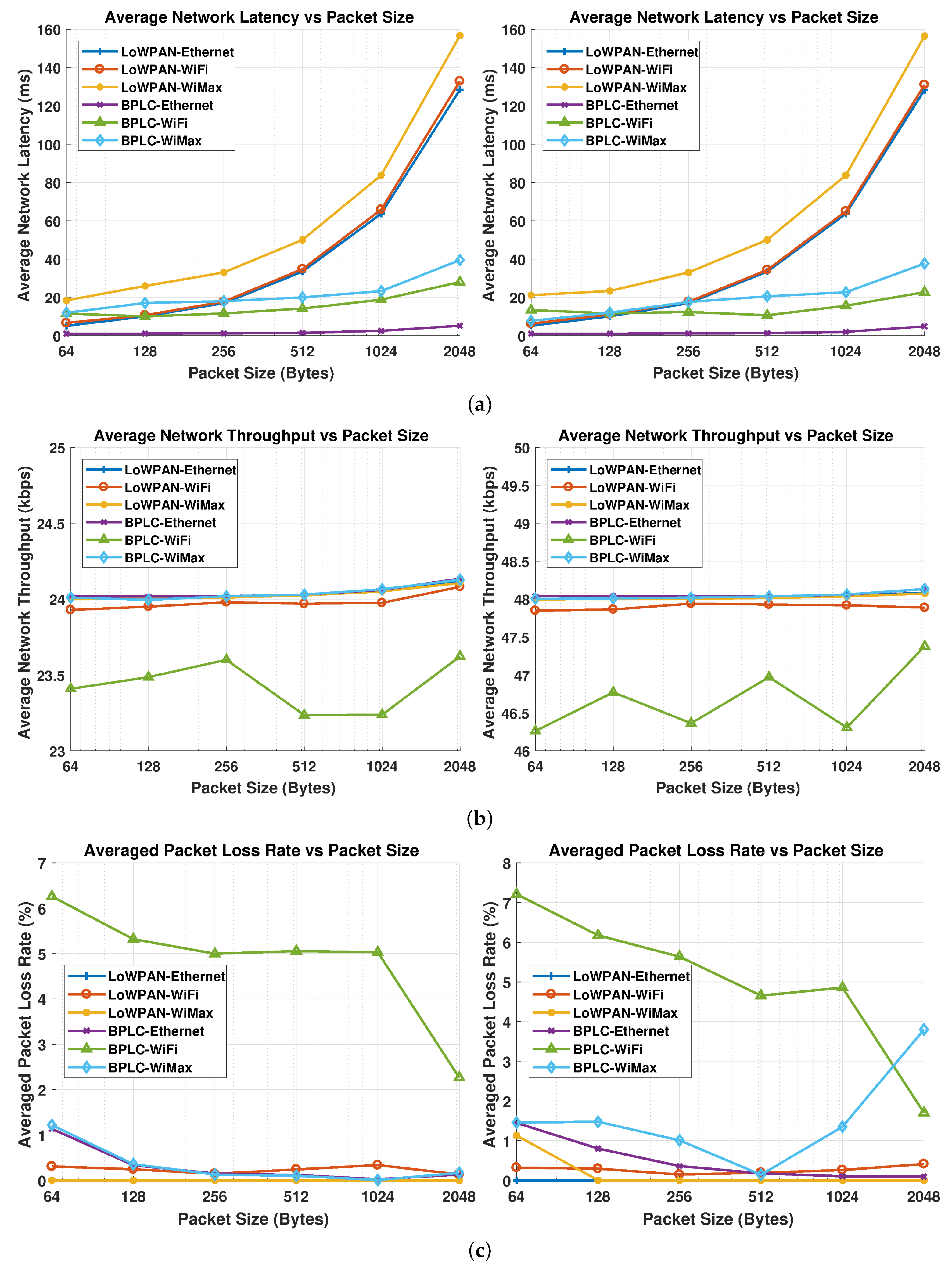
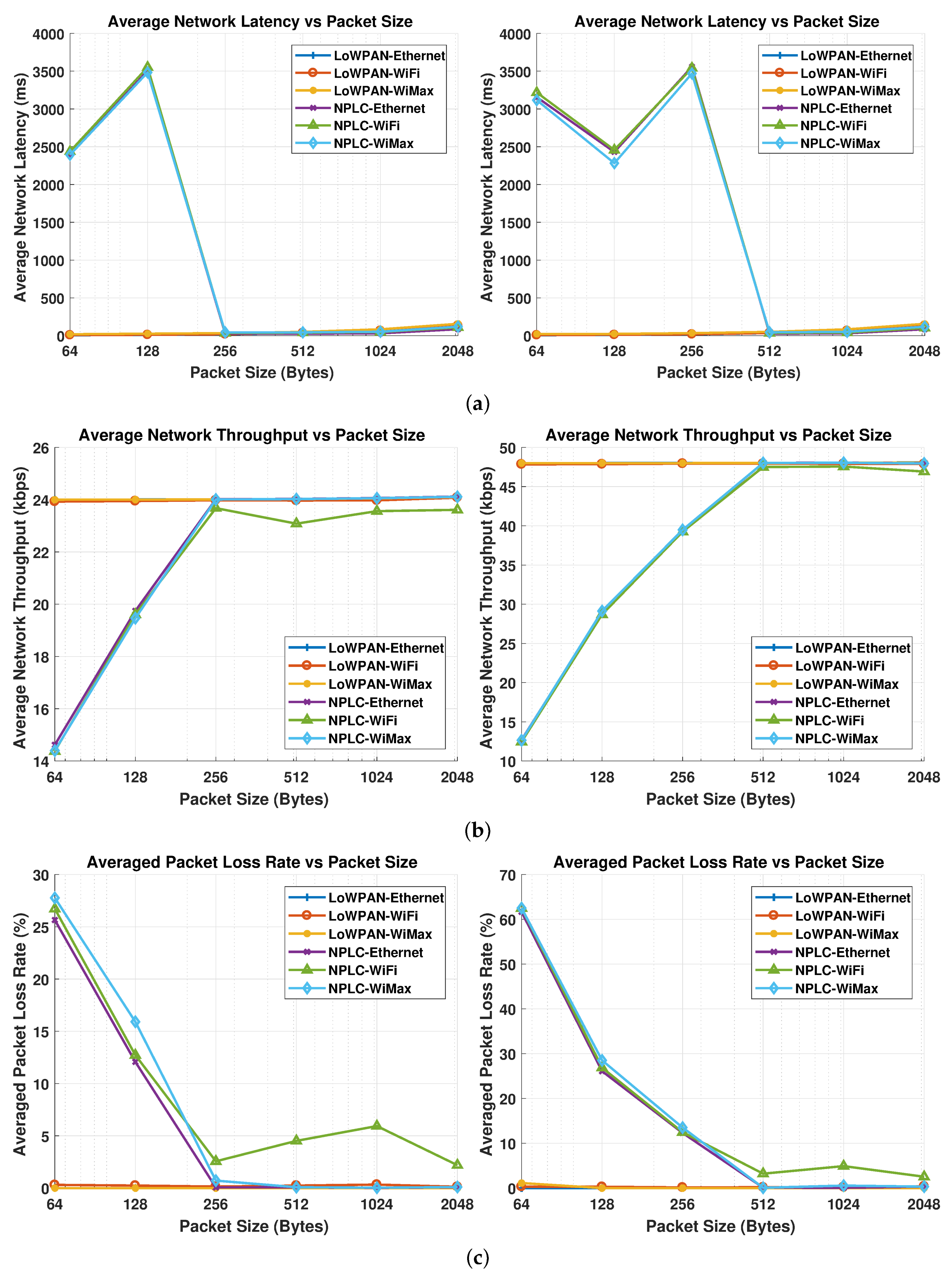
4.3. Performance Characterization of Hybrid Architectures

In this subsection, the simulation results of six hybrid systems integrated with Reference Test Case A (RTC-A) are presented and discussed. The main focus is on validating the third hybrid system design criteria of reliability, and evaluate the performance comparison in terms of three metrics. The performance characteristics of hybrid designs are investigated through the NS3 simulations developed above for the hybrid communication networks conveying the UDP traffic. To this end, we first set the optimal parameter configuration for each alternative communication module described in Table 2 and Table 3 in simulations according to the test results of Section 4.2. Then, the PV data traffic is parameterized following the distributed PV coordination applications. The PV packet size is thus set at 64, 128, 256, 512, 1024, and 2048 bytes [9]. The PV packet transmission rate is set at 16, 24, 32, 40, 48, 56 Kbps. In every simulation event, 10,000 packets were sent at each PV node with different data rates. The results were averaged among all paths and 100 runs.
Both the BPLC and NPLC situations are considered, because the PLC module supports both of them. Their comparative results are shown in Figure 4 and Figure 5, respectively. For BPLC and the other five alternative communication technologies, the simulation results show that the data rate 16–56 Kbps has almost no impact on the hybrid network performance. Thus only two cases of data rate—24 Kbps and 48 Kbps—are chosen to show the similarity. This is because that the bandwidth of each communication media with the lower bound of 250 Kbps is always more than the upper bound data rate of 56 Kbps for the PV applications, which causes no traffic congestion within the network. Therefore, the impact of data rate on the latency and packet loss rate performance can be ignored when the data rate is less than the bandwidth. Meanwhile, the NPLC-based hybrid system performance varies greatly with different data rates, but it shows the same trend; therefore, similar with BPLC case, only the cases of 24 Kbps and 48 Kbps are reported. The impact of combinations of packet size and transmission date rate on the hybrid network performance are examined in detail.

4.3.1. Latency Performance Comparison

Figure 4a and Figure 5a show that the single-trip latency performance is clearly grouped in terms of two alternative technologies applied in the PV-smart meter link, regardless of settings of packet size and data rate. The same observations are evident for throughput and packet loss rate in the case of NPLC. This result implicitly indicates that the communication technology of the PV-smart meter links with low capacity plays a more critical role than that of the smart meter-DC links with high capacity. This can be verified by the fact that in the hybrid communication architecture, the link with low-performance characteristics determines the overall network performance. In particular, the PV-smart meter link design dominates the latency characteristics of hybrid networks because it usually has relatively lower bandwidth. In addition, both the UDP packet size and data rate have an interesting effect on the latency performance of hybrid designs, as described next.
Figure 4a reveals that the average latency increases almost linearly with increasing packet size, which is consistent with results in [33]. This is because the payload of data frames in IEEE 802.15.4 vary from 2 to 127 bytes [34], and the BPLC supports the maximum transmission unit (MTU) of 1500 bytes. A larger packet will take a long time to transfer, resulting in more collisions at the PHY layer, thus higher latency. For example, for the 64-byte packet, the corresponding data frame payload in the LoWPAN cases is approximately 151 bytes by adding various protocol headers, which needs two data frames. In other words, the optimal packet size is 64 bytes for the cases of LoWPAN and BPLC regarding the latency metric only.
For the same setting of packet size and data rate, the Ethernet cable case always has the best latency performance in the smart meter-DC links, as we expected. Note that the LoWPAN-WiFi design outperforms the LoWPAN-WiMAX, whereas they are comparative in the PLC cases. This observation indicates that there are existing wireless interferences when both PV-smart meter and smart meter-DC links are using the wireless communication, which agrees with [34]. Considering the reliability of LoWPAN-based and BPLC-based designs, we found that the critical latency requirement of 300 ms is always satisfied with all settings of packet size and data rate. In particular, when the BPLC is employed from 2 to 30 MHz with an approximate 20-Mbps PHY rate [33] and IEEE 802.15.4 supports 250-Kbps bandwidth, the overall latency performance of BPLC-based designs is better than that of the LoWPAN cases.
Regarding different data rates, the latency performance of three NPLC-based hybrid designs always has the same trend, namely, the latency is very big when packet size less than the optimal value, whereas it is dramatically improved when packet size is from the optimal value to the upper bound of 2048 bytes, shown in Figure 5a. With increasing data rate, three NPLC-based hybrid networks have smoothly degrading latency performance: (a) the latency is getting much bigger for packet sizes from 64 bytes to the optimal value; (b) the optimal packet size increases. The performance of the NPLC-based designs highly depends on the data rate of the PV applications because of two important specifications. The NPLC delivers 500 Kbps at the PHY layer, whereas 20 Mbps PHY for the BPLC. Another reason is because of the physical modulation of the PLC protocols, in which one symbol is equal to 1536 bytes. This means that sending 64 bytes uses the same physical capacity as sending 1024 bytes, and the larger the transmitted packet, the more efficient the physical transmission [9]. Thus, we recalculate the required PHY rate considering the application data rate and packet size. Considering 24 Kbps, the required PHY rates for 64, 128, 256, 512, and 1024 bytes are 1125, 564, 288, 144, 72 Kbps, respectively. With the required PHY rate ≤ 500 Kbps with 256 bytes, the hybrid system can achieve the latency requirement of 300 ms. The same analysis also works for the case of 48 Kbps, and results in the optimal packet size of 512 bytes. Otherwise, the latency is too big for the distributed RES coordination applications. This indicates that higher data rates and larger packet sizes are needed to satisfy latency performance, and the feasible range of packet size is getting smaller. Therefore, for the PV application with packet size of 128 bytes and data rate of 24 Kbps, three LoWPAN-based, BPLC-Ethernet, and BPLC-WiMAX cases can satisfy the latency requirement, as well as throughput and packet loss rate in next subsections.
These simulation results can provide enough information or guidance on the distributed smart grid applications. For example, it will be discussed below how the voltage profile of the power system with high penetration of distributed Renewable Energy Sources (RESs) could be impacted if UDP packets were experiencing high communication delay. From the study of [20], it is concluded that the uncontrolled voltage level proportion compared with the non-time-delay results will almost linearly increase from 0 to 60% when the delay time varies from 0 to 3.0 s. By observing Figure 4a and Figure 5a, three guidance rules for the impact of nine hybrid architectures designs on the distributed voltage control application in an NAN can be drawn as (1) regardless packet size and data rate of PV control signals, the uncontrolled voltage proportion will be less than 2% for six LoWPAN and BPLC-based hybrid designs because the average delays of six cases are less than 0.16 s; (2) for three NPLC-based hybrid designs, the uncontrolled voltage proportion will also be less than 2% when the packet size ranges from 256 to 2048 bytes along with 24 Kbps data rate, or the packet size ranges from 512 to 2048 bytes along with 48 Kbps data rate; (3) while still for three NPLC-based hybrid designs, the uncontrolled voltage will suffer up 50–60% proportion due to the delay vary from 2.5 to 3 s, when in case of 24 Kbps data rate, the packet size is set to 64 or 128 bytes, or in case of 48 Kbps data rate, the packet size ranges from 64 bytes to 256 bytes.

4.3.2. Throughput Performance Comparison

As shown in Figure 4b and Figure 5b, it can be first verified that the application data rate is the benchmark value of throughput for the proposed hybrid network, and the higher data rate results in the higher overall throughput limited within the bandwidth. Except for the NPLC-base cases, the packet size changing almost has no impact of the throughput performance. The WiFi-based cases always have the lowest throughput due to higher packet loss rate caused by the unreliability of WiFi signal, as expected. Similar with latency, only when packet size ≥ the optimal value, the NPLC-based designs can achieve the expected throughput, shown in Figure 5b. It also can be observed that all the proposed hybrid designs satisfy the critical throughput requirement of 9.6 Kbps.

4.3.3. Packet Loss Performance Comparison

Figure 4c shows that three LoWPAN-based cases have the packet loss rate of less than the critical requirement of 1%, regardless of packet size and data rate. Although the BPLC exhibited an impressive latency performance in Figure 4a, this is a trade-off with the high packet loss rate in Figure 4c. Both BPLC-WiFi and BPLC-WiMAX cases almost cannot satisfy the 1% criteria with the higher data rate, and it is possible for the BPLC-Ethernet design to gain the criteria when the packet size ≥ 128 Bytes. For the NPLC cases, it is evident that the packet loss rate has the same behavior with latency and throughput, and both NPLC-WiFi and BPLC-WiFi always suffer the highest packet loss rate, approximately 2–7%. Thus, the required packet loss rate for the UDP packets is harder to attain compared to the other two performance metrics. Additionally, the NPLC-Ethernet and NPLC-WiMAX cases can gain the satisfactory packet loss rate only when packet size ≥ the optimal value.

5. Conclusions

This paper focuses on design of nine hybrid communication architectures, development of a suite of simulation models, and validation of critical system design criteria for distributed generation and storage devices coordination in the envisioned smart grid. From the validation results, we have the following key findings: (1) three LoWPAN-based hybrid architectures can satisfy three performance metrics, a single trip latency of 300 ms, throughput of 9.6 Kbps, and packet loss rate of 1%, without considering the settings of packet size and data rate; (2) both BPLC-WiFi and NPLC-WiFi designs always cannot satisfy the requirement of 1% packet loss rate; (3) for the PV monitoring application with packet size of 128 bytes and data rate 24 Kbps, three LoWPAN-based, BPLC-Ethernet, BPLC-WiMAX cases can achieve three metrics; (4) both NPLC-Ethernet and NPLC-WiMAX designs can satisfy three metrics only for the situations 24 Kbps data rate with packet size ranging from 256 to 2048 bytes, or 48 Kbps data rate with packet size ranging from 512 to 2048 bytes. The results, thereby provide valuable insights and guidance in designing future hybrid communication infrastructures for generic distributed applications in the smart grid. Especially, for the system voltage control application in the distribution system with high penetration of distributed RESs, there are two major guidance rules (1) for three NPLC-based hybrid designs, the uncontrolled voltage will suffer up 50–60% proportion due to the delay vary from 2.5 to 3 s; (2) while for other cases, the uncontrolled voltage will be less than 2%. Future work will be to evaluate these hybrid architecture designs with hardware-in-the-loop testing to validate performance from the device perspective.

Acknowledgments

This work was supported by the U.S. Department of Energy under Contract No. DE-AC36-08GO28308 with Alliance for Sustainable Energy, LLC, the Manager and Operator of the National Renewable Energy Laboratory. Funding for this work was provided by U.S. Department of Energy Office of Energy Efficiency and Renewable Energy Solar Energy Technologies Office. The U.S. Government retains and the publisher, by accepting the article for publication, acknowledges that the U.S. Government retains a nonexclusive, paid-up, irrevocable, worldwide license to publish or reproduce the published form of this work, or allow others to do so, for U.S. Government purposes.

Author Contributions

The paper was a collaborative effort among the authors. Jianhua Zhang, Adarsh Hasandka, and Jin Wei mainly carried out the development and validation of hybrid communication architectures. Anthony R. Florita and Bri-Mathias Hodge supervised this work. S. M. Shafiul Alam contributed to the literature review and manuscript preparation. Tarek Elgindy contributed to the test case.

Conflicts of Interest

The authors declare no conflicts of interest.

References

  1. Karnaouskos, S. The Cooperative Internet of Things enabled Smart Grid. In Proceedings of the 14th IEEE International Symposium on Consumer Electronics (ISCE), Braunschweig, Germany, 7–10 June 2010. [Google Scholar]
  2. Moursi, M.; Zeineldin, H.; Kirtley, J.; Alobeidli, K. A Dynamic Master/Slave Reactive Power-management Scheme for Smart Grids with Distribution Generation. IEEE Trans. Power Deliv. 2014, 29, 1157–1167. [Google Scholar] [CrossRef]
  3. Logenthiran, T.; Srinivasan, D. Intelligent Management of Distributed Storage Elements in a Smart Grid. In Proceedings of the 2011 IEEE Ninth International Conference on Power Electronics and Drive Systems (PEDS), Singapore, 5–8 December 2011; pp. 855–860. [Google Scholar]
  4. Molina, M.G. Distributed Energy Storage Systems for Applications in Future Smart Grids. In Proceedings of the 2012 Sixth IEEE/PES Transmission and Distribution: Latin America Conference and Exposition (T D-LA), Montevideo, Uruguay, 3–5 September 2012; pp. 1–7. [Google Scholar]
  5. Vermesan, O.; Friess, P.; Guillemin, P.; Gusmeroli, S.; Sundmaeker, H.; Bassi, A.; Jubert, I.S.; Mazura, M.; Harrison, M.; Eisenhauer, M.; et al. Internet of Things Strategic Research Roadmap. Internet Things Glob. Technol. Soc. Trends 2011, 1, 9–52. [Google Scholar]
  6. Kuzlu, M.; Pipattanasomporn, M.; Rahman, S. Communication Network Requirements for Major Smart Grid Applications in HAN, NAN and WAN. Comput. Netw. 2014, 67, 74–88. [Google Scholar] [CrossRef]
  7. Budka, K.; Deshpande, J.; Doumi, T.; Madden, M.; Mew, T. Communication Network Architecture and Design Principle for Smart Grids. Bell Labs Tech. J. 2010, 15, 205–227. [Google Scholar] [CrossRef]
  8. Abdrabou, A. A Wireless Communication Architecture for Smart Grid Distribution Networks. IEEE Syst. J. 2016, 10, 251–261. [Google Scholar] [CrossRef]
  9. Giustina, D.; Rinaldi, S. Hybrid Communication Network for the Smart Grid: Validation of a Field Test Experience. IEEE Trans. Power Deliv. 2015, 30, 2492–2500. [Google Scholar] [CrossRef]
  10. Cataliotti, A.; Cosentino, V.; di Cara, D.; Guaiana, S.; Panzavecchia, N.; Tin, G.; Gallo, D.; Landi, C.; Landi, M.; Luiso, M. Experimental Evaluation of an Hybrid Communication System Architecture for Smart Grid Application. In Proceedings of the IEEE International Workshop on Applied Measurements for Power Systems (AMPS), Aachen, Germany, 23–25 September 2015; pp. 96–101. [Google Scholar]
  11. Salvadori, F.; Gehrke, C.S.; de Oliveira, A.C.; de Campos, M.; Sausen, P.S. Smart Grid Infrastructure Using a Hybrid Network Architecture. IEEE Trans. Smart Grid 2013, 4, 1630–1639. [Google Scholar] [CrossRef]
  12. Ahmed, M.; Kim, Y. Communication Networks of Domestic Small-Scale Renewable Energy Systems. In Proceedings of the 4th International Conference on Intelligent Systems, Modelling and Simulation, Bangkok, Thailand, 29–31 January 2013. [Google Scholar]
  13. Rajalingham, G.; Ho, Q.-D.; Le-Ngoc, T. Evaluation of an Efficient Smart Grid Communication System at the Neighbor Area Level. In Proceedings of the 11th IEEE Consumer Communications and Networking Conference (CCNC), Las Vegas, NV, USA, 10–13 January 2014; pp. 426–431. [Google Scholar]
  14. Saputro, N.; Akkaya, K.; Guvenc, I. Privacy-aware Communication Protocol for Hybrid IEEE 802.11s/LTE Smart Grid Architectures. In Proceedings of the 40th Annual IEEE Conference on Local Computer Networks (LCN), Clearwater Beach, FL, USA, 26–29 October 2015. [Google Scholar]
  15. Budka, K.; Deshpande, J.; Thottan, M. Communication Networks for Smart Grids Making Smart Grid Real, 1st ed.; Springer: London, UK, 2014. [Google Scholar]
  16. Berger, L.; Iniewski, K. Smart Grid Applications, Communications, and Security; Wiley: New York, NY, USA, 2012; ISBN 978-1118004395. [Google Scholar]
  17. Duan, B.; Kammen, D.; Wu, J.; Macuha, M.; Tariq, M.; Asfaw, S.A.; Sato, T.; Zhou, Z. Smart Grid Standards: Specifications, Requirements, and Technologies; Wiley Online Library: Malden, MA, USA, 2015. [Google Scholar]
  18. Rahman, S.; Pipattanasomporn, M.; Teklu, Y. Intelligent Distributed Autonomous Power Systems (IDAPS). In Proceedings of the IEEE PES Annual General Meeting, Tampa, FL, USA, 24–28 June 2007. [Google Scholar]
  19. Pipattanasomporn, M.; Feroze, H.; Rahman, S. Multi-agent Systems in a Distributed Smart Grid: Design and Implementation. In Proceedings of the 2009 IEEE/PES Power Systems Conference and Exposition, Seattle, WA, USA, 15–18 March 2009; pp. 1–8. [Google Scholar]
  20. Xu, J.; Sun, H.; Dent, C. The Coordinated Voltage Control Meets Imperfect Communication System. In Proceedings of the 2016 IEEE PES Innovative Smart Grid Technologies Conference Europe (ISGT-Europe), Ljubljana, Slovenia, 9–12 October 2016; pp. 1–5. [Google Scholar]
  21. Wu, J.; Yang, T.; Wu, D.; Kalsi, K.; Johansson, K.H. Distributed Optimal Dispatch of Distributed Energy Resources over Lossy Communication Networks. IEEE Trans. Smart Grid 2017, 8, 3125–3137. [Google Scholar] [CrossRef]
  22. Wu, Y.; Wei, J.; Hodge, B.M. A Distributed Middleware Architecture for Attack-resilient Communications in Smart Grids. In Proceedings of the IEEE International Conference on Communications (ICC), Paris, France, 21–25 May 2017; pp. 1–7. [Google Scholar]
  23. Gungor, V.C.; Sahin, D.; Kocak, T.; Ergut, S.; Buccella, C.; Cecati, C.; Hancke, G.P. A Survey on Smart Grid Potential Applications and Communication Requirements. IEEE Trans. Ind. Inform. 2013, 9, 28–42. [Google Scholar] [CrossRef]
  24. U.S. Department of Energy. Communications Requirements of Smart Grid Technologies; Report of Department of Energy; U.S. Department of Energy: Washington, DC, USA, 2010; pp. 1–69.
  25. NS-3. Available online: https://www.nsnam.org (accessed on 8 March 2018).
  26. Aalamifar, F.; Schloegl, A.; Harris, D.; Lampe, L. Modelling Power Line Communication Using Network Simulator-3. In Proceedings of the IEEE Global Communications Conference (GLOBECOM), Atlanta, GA, USA, 9–13 December 2013. [Google Scholar]
  27. Nikhale, S.; Mankar, C.; Auti, D. Implementation of 802.16 using NS-3 Simulator. In Proceedings of the IEEE 9th International Conference on Intelligent Systems and Control (ISCO), Coimbatore, India, 9–10 January 2015. [Google Scholar]
  28. Farooq, J.; Turletti, T. An IEEE 802.16 WiMAX Module for the NS-3 Simulator. In Proceedings of the 2nd International Conference on Simulation Tools and Techniques (SIMULTools), Rome, Italy, 2–6 March 2009. [Google Scholar]
  29. Hiertz, G.R.; Denteneer, D.; Max, S.; Taori, R.; Cardona, J.; Berlemann, L.; Walke, B. IEEE 802.11s: The WLAN Mesh Standard. IEEE Wirel. Commun. 2010, 17, 104–111. [Google Scholar] [CrossRef]
  30. Schneider, K.; Chen, Y.; Chassin, D.; Pratt, R.; Engel, D.; Thompson, S. Modern Grid Initiative: Distribution Taxonomy Final Report; Pacific Northwest National Laboratory: Richland, WA, USA, 2008.
  31. Khach, E.; Jacobsen, K.; Skov, M.; Hojholt, N.; Sorensen, R.; Olsen, R. Investigation of QoS in PLC and Evaluation of a NS-3 PLC Simulator; Study Report of Aalborg University; Aalborg University: Aalborg, Denmark, 2014. [Google Scholar]
  32. Andreev, K.; Boyko, P. Simulation Study of VoIP Performance in IEEE 802.11 Wireless Mesh Networks. In Proceedings of the Third International Workshop on Multiple Access Communications, Barcelona, Spain, 13–14 September 2010; pp. 139–150. [Google Scholar]
  33. Augustine, I.; Bamidele, A.; Khaled, R. Broadband PLC for Clustered Advanced Metering Infrastructure (AMI) Architecture. Energies 2016, 9, 1–19. [Google Scholar]
  34. Petrova, M.; Riihijarvi, J.; Mahonen, P.; Labella, S. Performance Study of IEEE 802.15.4 using Measurements and Simulations. IEEE Wirel. Commun. Netw. Conf. 2006, 1, 487–492. [Google Scholar]
Figure 1. Envisioned smart grid communication networks.
Energies 11 00871 g001
Figure 2. NS3 simulation model of hybrid architectures with user datagram protocol (UDP)/transmission control protocol (TCP).
Energies 11 00871 g002
Figure 3. Screenshot of LoWPAN-WiFi network animation on top of RTC-A.
Energies 11 00871 g003
Figure 4. Performance comparison of six hybrid communication designs in terms of UDP packet size and data rate–BPLC. (a) Latency for data rate 24–48 Kbps; (b) Throughput for data rate 24–48 Kbps; (c) Packet Loss Rate for data rate 24–48 Kbps.
Energies 11 00871 g004
Figure 5. Performance comparison of six hybrid communication designers in terms of UDP packet size and data rate–NPLC. (a) Latency for data rate 24–48 Kbps; (b) Throughput for data rate 24–48 Kbps; (c) Packet Loss Rate for data rate 24–48 Kbps.
Energies 11 00871 g005
Table 1. Hybrid communication architectures.
Hybrid TypeHome Area NetworkNeighborhood Area Network
Hybrid 1LoWPANEthernet cable
Hybrid 2LoWPANWiFi
Hybrid 3LoWPANWiMax
Hybrid 4PLCEthernet cable
Hybrid 5PLCWiFi
Hybrid 6PLCWiMax
Table 2. Basic configuration and parameter verification of PV-Smart Meter Links.
MediumParameterValuesImpact
LoWPANPropagation loss modelLogDistance, FixedRss, Randomhigh
Propagation delay modelConstantSpeed, Randomhigh
PLCSpectrum modelTimeInvariant–( 2 × 10 6 , 3 × 10 7 , 1146), ( 2 × 10 6 , 3 × 10 7 , 500), ( 2 × 10 6 , 10 8 , 300), ( 2 × 10 6 , 3 × 10 7 , 100); G3–(0, 10 5 , 300), (60 Hz, 2240 us), (0, 5 × 10 4 , 5)high
Payload modulation coding schemeQAM64_rateless, QAM32_rateless, QAM4_rateless, QAM64_12_21, BPSK_1_2, BPSK_ratelesshigh
Header modulation codingBPSK_1_2, BPSK_1_4medium
Transmit PSD 10 8 , 10 6 no
Noise 10 9 , 10 10 no
Cable typeNAYY50SE, NAYY150SE, AL3x95XLPE, MV_Overhead, NYCY70SM35no
Table 3. Basic configuration and parameter verification of smart Meter-DC Links.
MediumParameterValuesImpact
Ethernet cableData rate100 Mbps, 30 Mbpsno
Delay3.33 us, 6560 nanoseclow
Encapsulation modeDix, Llc, IpArp, EthernetV1no
Max transmit unit1500 bytes, 1492 bytesno
WiFi meshProtocol stackDot11sStack, FlameStackmedium
Mac typeRandomStart −0.1 s, 0.5 slow
Propagation delay modelRandom, ConstantSpeedlow
Propagation loss modelFixedRss, Friss, LogDistance, Randomhigh
WiFi standard80211a, 80211b, 80211glow
Spread interface channelNumberOfInterface −3, 2, 1low
Remote station managerAarf, Arf, Aparf, Aarfcd, Amrr, Ideal, Cara, Minstrel, ConstantRate, Rraalow
WiMAXPhy layer modulationQAM16-12, QAM16-34, QAM64-32, QAM64-34, BPSK-12, QPSK-12, BPSK-34high
Service flowUGS, RTPS, NRTPS, BEmedium
Propagation modelFriis, Cost231, Random, Logmedium
SchedulerSIMPLE, MBQOS, RTPSlow

