Article

A Superconducting Induction Motor with a High Temperature Superconducting Armature: Electromagnetic Theory, Design and Analysis

1
School of Electrical Engineering, Beijing Jiaotong University, Beijing 100044, China
2
Robinson Research Institute, Victoria University of Wellington, Wellington 33436, New Zealand
*
Author to whom correspondence should be addressed.
Energies 2018, 11(4), 792; https://doi.org/10.3390/en11040792
Submission received: 8 March 2018 / Revised: 28 March 2018 / Accepted: 28 March 2018 / Published: 29 March 2018

Abstract

:
Large electric superconducting machines are being sought to solve emissions challenges in aircraft and provide a solution to >12 MW wind turbine electricity generation. Superconducting motors with only high temperature superconducting (HTS) armatures can offer advantages of high reliability, high power density, and high efficiency compared with conventional superconducting motors. In this paper, a novel HTS squirrel-cage induction motor is proposed for high speed operation, which adopts the structure of HTS windings with a certain inclination angle in the stator slots. Due to the limitation of curvature radius of superconducting tapes, the pitch of HTS windings can be only set to 1 and adopt the short pitch arrangement structure, which such design details of the HTS motor would ensure the superconducting coils can undertake larger current and reduce AC losses. In order to keep the HTS windings in superconducting state and larger current density, a special fixed cryogenic cooling system below 70 K with the method of gas extraction and decompression, which is made of aramid fiber, has been fabricated and the whole structure of the stator is placed in liquid nitrogen. According to the motor control principles and electromagnetic field theory, the electrical performances of the novel designed stator-HTS motor, which driven by the variable-voltage variable-frequency (VVVF) inverter, are analyzed including the flux density distributions, the torque, the induced electromotive force, losses and efficiency by using the finite element method. Finally, the components of HTS squirrel-cage induction motor have been manufactured according to the designed parameters. Next step, the motor will be assembled and tested.

1. Introduction

The continuous improvement of the properties of high temperature superconducting materials creates more opportunities for high power superconducting motors [1]. Compared with the conventional machines of same power, high temperature superconducting (HTS) motors have the advantages of small volume, light weight, high power density and being less expensive to operate because of their high current density, ironless design, high magnetic field, and high operating temperature [2,3,4,5,6,7]. The potentially significant size, weight, cost and efficiency benefits of superconducting machines, which are especially important factors in these applications such as electric propulsion in ships, all-electric aircraft propulsion, electric vehicles and wind generators, etc., will change the development direction of the electrical machinery industry [8,9,10,11,12,13,14].
However, most superconducting machines adopt superconducting material as the rotor poles for the field to supply high air-gap magnetic flux density, consequently the HTS motor has high power density and has been studied by many researchers and institutions, but this structure brings some problems such as cooling, maintenance, mechanical speed and manufacture cost, etc., and this technology is also complex [15,16,17,18]. In addition, because the superconducting magnets face an air gap with a high flux density at all times, the magnetic flux density in the superconducting coils is also high. This will affect the critical current of the superconducting tapes, so the operation temperature of superconducting magnets must decrease to 20–30 K to eliminate this influence. Therefore, the costs of cooling increase.
We have focused on the HTS induction motor [19,20,21,22], in which the superconducting material is only applied to the stator part. The HTS induction motors avoid the key problems of the rotor dynamic seal and the rotor mechanical strength compared with the conventional superconducting motor under the high speed operation. The Japanese scholars Sekiguchi and Nakamura developed a 20 kW induction/synchronous full superconducting motor, which utilizes superconducting materials on both the stator and the rotor to maximize the power and torque density. The experiment proved that the motor realized synchronous speed more than 1000 rpm for the first time [23]. At present, the demand for higher-speed high-power motors is becoming more and more urgent, so the development of higher speed superconducting motors is a research hot spot.
In this study, we focus on applying high temperature superconductivity in a 500 kW, 11,995 rpm HTS induction motor with the superconducting armature coils. The stator components of the motor are composed of a stator core, HTS windings, a windings support frame, and a fixed cryogenic cooling system, and the rotor consists of conventional squirrel-cage type cast aluminium bars, a laminated core and a rotation shaft. In this paper, the rotor structure of the superconducting motor is designed firstly, and the electromagnetic structure parameters of the rotor are obtained. Then, according to the characteristics of the superconducting material, the stator part is designed, including the winding arrangement structure, the cooling system and so on. Then, the simulation model is established. The finite element software is used to calculate and evaluate the performance of the motor. Finally, according to the design parameters, the components of HTS squirrel-cage induction motor have been manufactured and the motor will be assembled and tested in the next stage.

2. Electromagnetic Design of High Temperature Superconducting Induction Motor

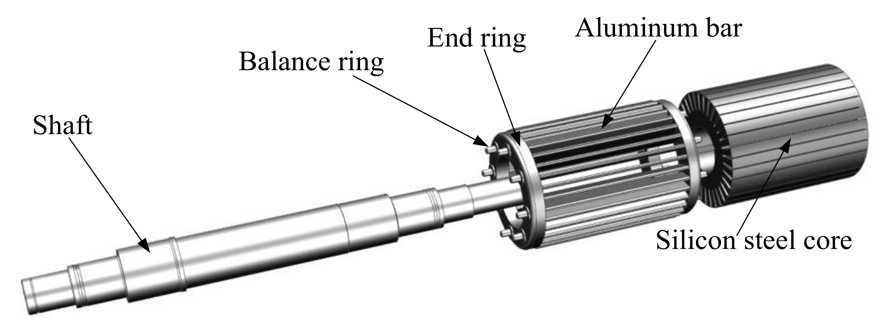
2.1. Rotor Structure Design

Figure 1 shows the squirrel cage rotor exploded diagram of the proposed HTS induction motor, which is composed of cast aluminum bars, cast aluminum end rings, balance rings, silicon steel core and shaft. The HTS induction motor is powered by a frequency converter when it is running, so the skin effect generated in the rotor conductor owing to the harmonics in the frequency conversion power supply reduces the effective cross sectional area of the conductor and increases the resistance. As a result, the rotor losses are significantly increased which account for a large proportion of the total loss of the HTS induction motor, so the influence of the skin effect on rotor electromagnetic design must be seriously considered.
According to the design principle of the HTS induction motor, when considering skin effect, the resistance of the cast aluminum bars and the end rings of the squirrel cage rotor can be calculated by following equations [24]:
R v = ξ v ( K k b l b ρ b Q 2 A b + K 2 D r ρ r π p 2 A r ) .
where, K is the conversion coefficient of resistance, kb is the resistance increase coefficient, lb is the cast aluminum bar length, ρb and ρr are the resistivity of the cast aluminum bar and the end ring respectively, Q2 is the slot number of rotor, Ab and Ar are the cross-sectional area of the cast aluminum bar and the end ring respectively, Dr is the average diameter of end ring, p is the pole number, ξv is the calculation coefficient when considering the skin effect.
Wherein:
ξ v = 0.1987 h 2 w v v 2 π ρ b .
where, h2 is the height of the cast aluminum bar, ωv is the harmonic frequency, v is the harmonic order.
As can be seen from Equation (1), the resistance of the cast aluminum bars and the end rings with the skin effect decreases with the increase of the rotor slot number and the cross section area, so, the slot type and the number of slots play an important role in reducing the rotor skin effect. Through the electromagnetic optimization calculation, the main structure parameters of the rotor are shown in Table 1. The whole rotor weight is 36.8 kg.

2.2. Stator Design

Due to the characteristics of the superconducting tapes themselves, the critical step of stator winding design is to determine the structure of the HTS coils and their arrangements. The specification parameters YBCO tape are shown in Table 2, which is made from American AMSC’s amperium copper laminated HTS wire.
The critical current is 180 A at 77 K. The width of a tape is 4.8 mm. The thickness of a superconducting layer is around 0.18 mm. Based on the experimental measurements and the data provided by the Robinson Research Institute of Victoria University of Wellington [25], the critical current curves of YBCO at the different temperature in parallel and vertical fields respectively are obtained, as shown in Figure 2. It can be seen from the Figure 2, the critical current of the AMSC’s amperium copper laminated HTS wire subjected to the vertical magnetic field decreases more heavily than that of the parallel field. When the YBCO tape is operating at 70 K, the critical current is about two times that at 77 K.
According to Table 2, some limitations which can constrain the minimum size of the stator structure have to be pointed out before the design of the stator windings is carried out. Firstly, a YBCO-coated conductor is in the form of a two-dimensional flat tape rather than a one-dimensional round wire, therefore the bending direction of the conductor can only occur in the dimension perpendicular to the surface of the tape. The mechanical property of the conductor also determines that the tape cannot be twisted over a short length. These factors limit the HTS coil to one configuration, i.e., wound into a racetrack shape, as shown in Figure 3. W is the width of the racetrack coil, which is determined by the product of the thickness of the YBCO tape and the number of turns. H is the width of the racetrack coil, which is two times the width of YBCO tape. R is the bending radius in the end of coil. L is the straight line length.
In addition, the other major limitation is the minimum bending radius of the tape, which in the case of the AMSC type, is 50 mm. When HTS wires are bent beyond their allowable radius, the critical current decreases rapidly and irreversibly [26], so one of the main constraints in fabricating HTS windings is its allowable bending radius. In the design, the length of the bending radius R in Figure 3 must be larger than 50 mm. This factor determines the minimum size of a single HTS coil and significantly affects the optimum power density of HTS induction motor that can be achieved. What’s more, another important limitation is that the performance of the tape is much more sensitive to the magnetic field perpendicular to its surface than that parallel to its surface. The maximum critical current in the tape decreases as the perpendicular magnetic field increases, and the AC losses increase significantly when the tape is subjected to a large AC perpendicular field. Therefore, a good HTS windings design always tends to avoid exposing the surface of the tape to the large component of the magnetic field produced by the stator and rotor.
Generally, the armature winding of a conventional motor requires a lot of tight radius bends in the end region which are not acceptable for YBCO tapes which have a maximum bending strain of about 0.25%. Figure 4 and Figure 5 show the 3D configuration of the windings and the rotor in region of the winding bar section and the winding end part respectively. The armature winding in the HTS induction motor designed is made of six single flat-loop coils which can be wound as flat racetrack pancake coils with a bend inner radius of 50 mm that is the minimum allowable bend radius. When the HTS coil designed is used to form a three-phase winding, the pitch of HTS winding can be only set to 1 and adopt the short pitch arrangement structure with a certain inclination angle in case of interference in the end region. Windings made from coils of this type are not frequently used.
Based on the arrangement characteristics of the superconducting coils above, an open rectangular slot is selected as the stator slot type, which is processed into the chamfer structure with a certain inclination angle at the bottom of the slot, which is equal to the inclination angle of the winding. According to the electromagnetic calculation, the dimension of the stator slot is finally obtained, as shown in Figure 6. The slot width is 31.8 mm. The slot height is 48.4 mm. Chamfer dimensions of the slot bottom are 7.5 mm and 10mm respectively. The slot structure can not only prevent the coil from interference in the end region of HTS winding, but also solve the difficult problem of fixing the coil in the slot. The arrangement structure of the final winding is shown in Figure 7.
According to the basic structure of HTS induction motor designed above, the 2D finite-element model in Figure 7 is used to analyze the flux density distribution of a HTS coil. The HTS coil was designed to operate 150 A in rms value, corresponding to an armature frequency of 200 Hz. As shown in Figure 8, the flux density distribution in the vertical direction and parallel direction of the superconducting coils of HTS induction motor is predicted by the finite element method (FEM). Figure 8 shows the results the maximum flux density at vertical direction of HTS coils is 0.192 T, and that is 0.554 T at the parallel direction when the motor. According to relationship between critical current and background field of YBCO tape in Figure 2, the critical current is not exceeded at 77 K, and the HTS coils can be operated continually. AC loss can be approximately estimated as a sum of magnetization loss due to the AC perpendicular field and the transport loss due to the AC current [27]. The approximation with six HTS coils due to this current and field is 659 W. For the HTS motor designed with output power of 500 KW, the loss ratio is less than 0.14%.
Through the above analysis, the fundamental structure of the proposed HTS motor stator has been determined, as shown in Figure 7. The stator components of the motor is composed of a stator core, HTS windings, windings supports, and a fixed cryogenic cooling system. And the whole structure of the stator is placed in cryogenic cooling system with liquid nitrogen. According to the motor design program compiled, the main structural parameters of the stator part are obtained, as shown in Table 3. The total weight of the HTS induction motor stator is about 106 kg.

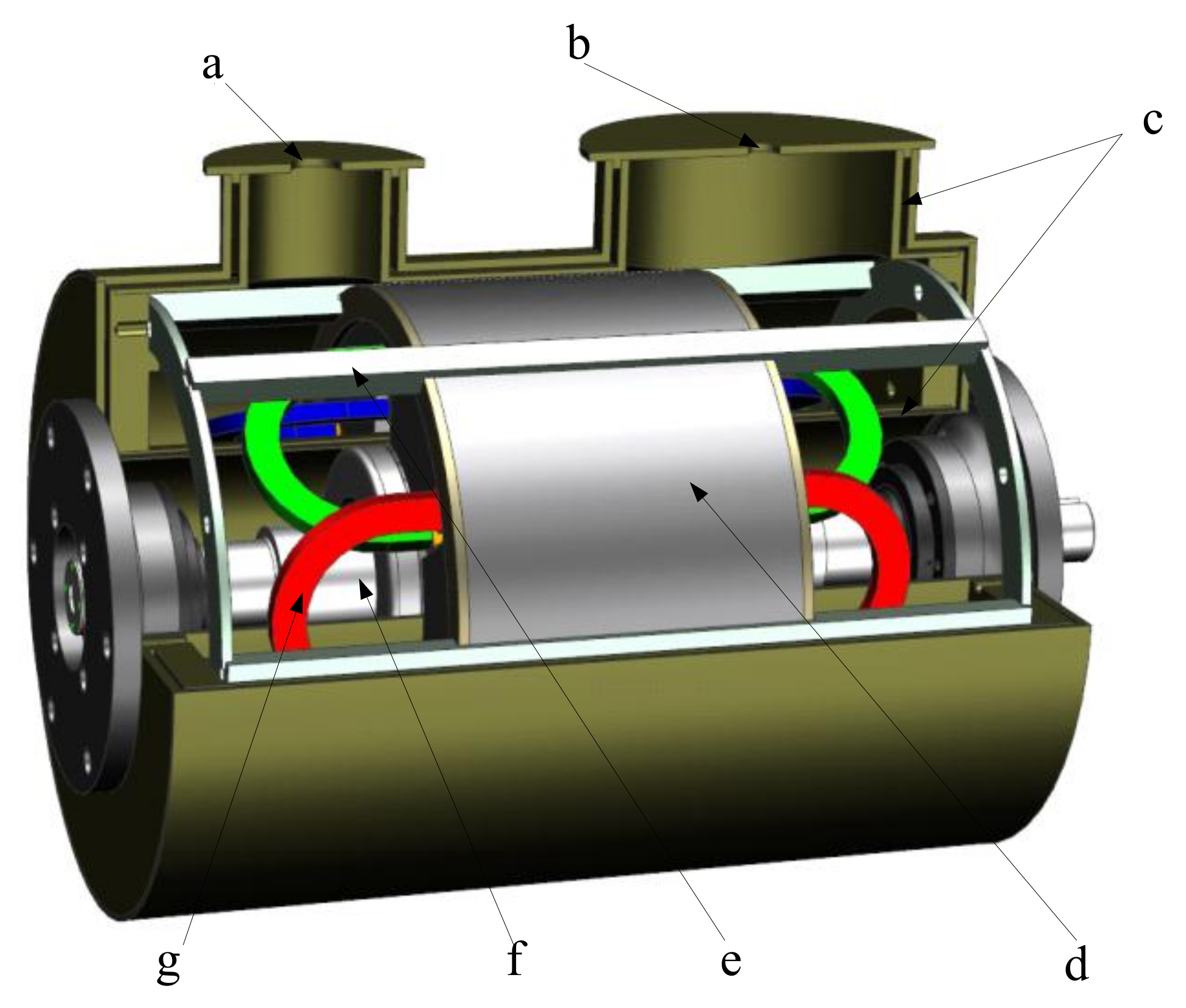
2.3. Cryogenic Cooling System Design

The cryogenic cooling system of an HTS motor, which has an extremely important role in maintaining the superconducting state in superconductive windings, is a challenge to design. In practice each superconducting coil of HTS motor should have its own cryostat and conduction cooling system. In this project we did not have sufficient budget to build the six cryostats, however we could use a single cryostat over the armature in order to investigate the performance of the motor, so in the HTS induction motor, the cooling method of the superconducting winding adopts the immersion type, and the cryogenic system passes through the air gap between the stator and the rotor. Therefore, in order to ensure the performance of the motor, the material in the air gap between the stator and the rotor in the cooling system must be non-magnetic and non-conductive. When the mechanical strength and thermal insulation effect are satisfied, the smaller the wall thickness of the cooling system, the better the performance of the motor. In the motor designed, the air gap between the stator and the rotor is only 6 mm, so the mechanical strength of the cooling system wall has to be very high. In addition, as the walls of the cooling system are very thin, the thermal insulation ability of the material are very demanding. For these reasons, a lot of research work was done, and finally, the reinforced aramid fiber material was chosen to make the Dewar.
Figure 9 shows the fundamental structure of the cryogenic cooling system made of the aramid material with the complete motor, which is a double layer with thermal insulation material in the middle and pumped into a vacuum. Of course, using such a single cryostat has the disadvantage that there is a significant cooling penalty associated with cooling the armature iron losses in the cryogenic environment. The authors opted to neglect the cooling of the iron losses in this non-optimal cryostat configuration because in a final machine the iron would be air or liquid cooled. The design and performance calculation of the Dewar will be explained in detail in a subsequent publication.
Today, most HTS motors are designed to work in about a 77 K situation. The critical temperature of some new superconductors is seen to be much higher, but their usages are extremely limited because of their low availability and extremely high cost. To cool HTS tapes to 77 K, liquid nitrogen is the best choice because of its low cost and its availability. To ensure a larger current that the superconducting coils can undertake, it is necessary to lower the temperature for the cryogenic cooling system with the method of gas extraction and decompression, which can be below 70 K. Based on the head load of the HTS coils and the iron loss, a liquid nitrogen tank with a pressure valve can continuously pour liquid nitrogen into the cooling system to ensure the safe and stable operation of the HTS induction motor.

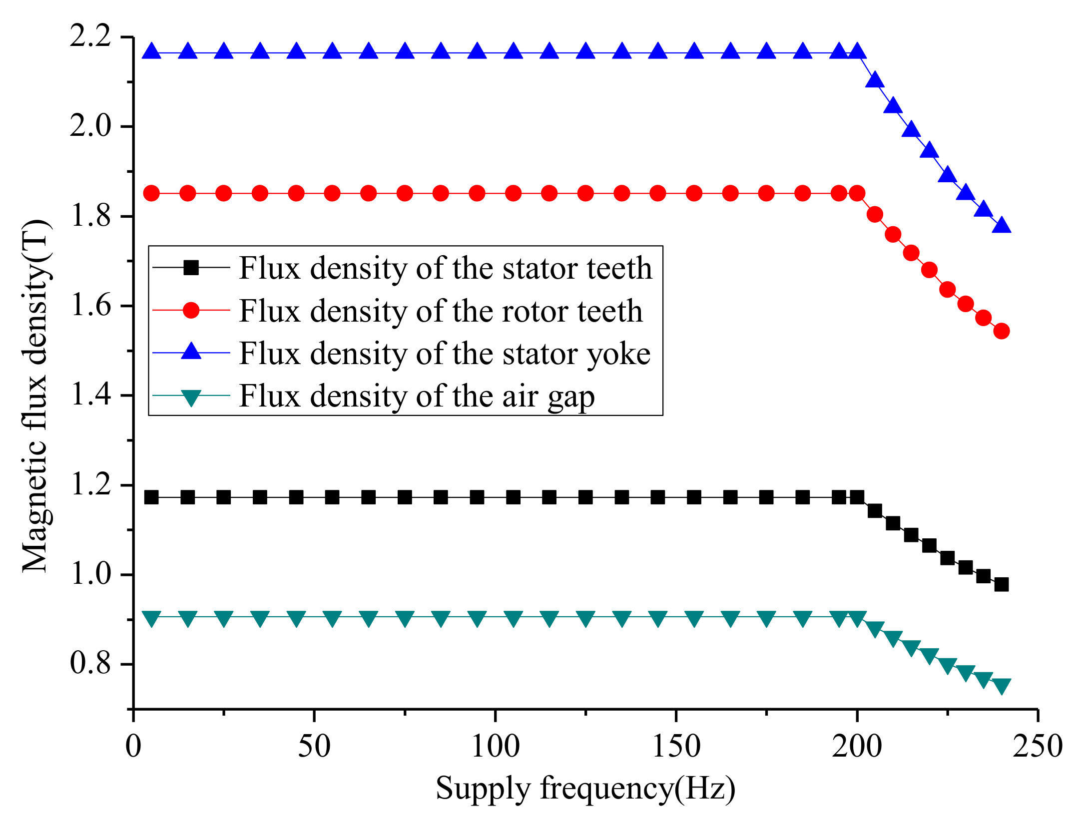
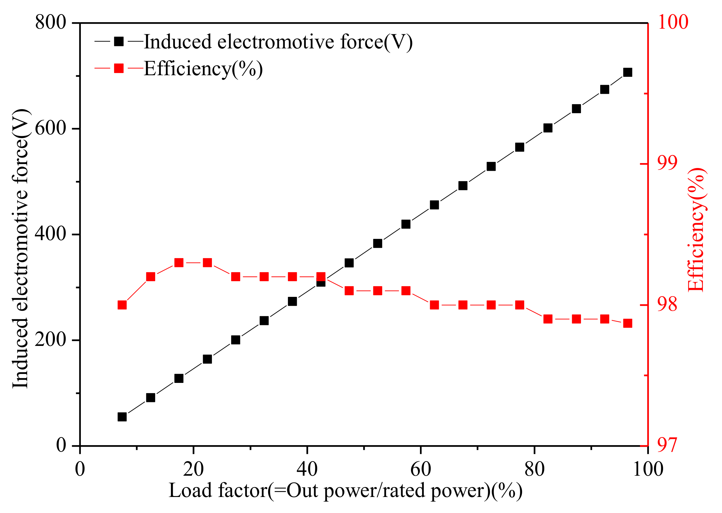
3. Predicted Electrical Performance of High Temperature Superconducting Induction Motor
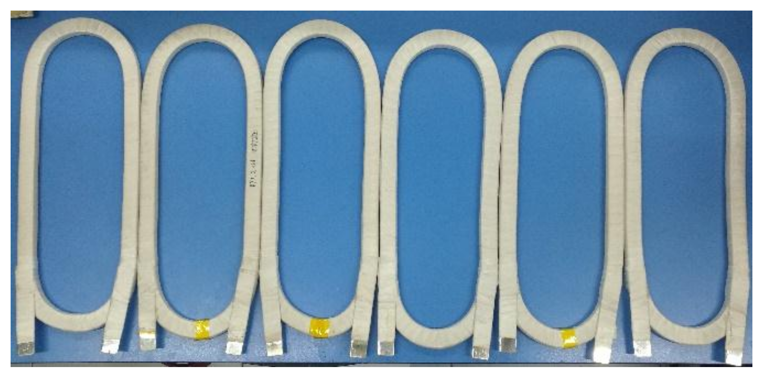
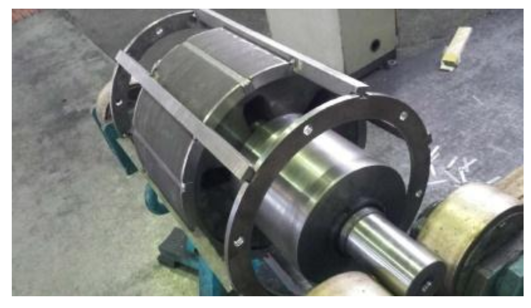
According to the basic dimensions obtained in the previous section, a finite element model considering the motor control strategy is built to calculate the performance of the HTS induction motor. In this motor, constant flux control method and flux weakening control method are used for speed regulation. Figure 10 represents the characteristics curves of output power and torque according to the variation of the operating supply frequency. It can be seen that the HTS induction motor operates in a constant torque state below the rated point and then in a constant power state above the designated point. As shown in Figure 10, when the HTS induction motor outputs the maximal torque, the motor’s power is 500 kW and it will become larger by other reasonable designs based on maximal torque.
We first calculate the magnetic flux density distribution of each part of the HTS induction motor. Figure 11 shows the curves of the magnetic flux density of each part with the supply frequency calculated using proprietary motor design software from Professor Zhang of Beijing Jiaotong University. Figure 12 shows the flux density plot for the motor. The calculations shown in Figure 11, have the maximum flux density occurring in the stator yoke not the stator teeth which is unusual compared with other common motors. This is the result of the use of large-size fan-shaped tooth in the motor and the constriction of flux in the stator yoke due to the drive to reduce yoke mass, and can be seen in the flux density plot in Figure 12. According to the graph, the magnetic flux density of each part of the motor remains unchanged with the increase of supply frequency in the constant flux stage and decreases in the stage of weakening magnetic control. It can be noted that the flux density of the air gap is about 0.9 T in the constant flux stage. As a result, the magnetic flux density of each part of the motor is within the allowable range of the ferromagnetic material saturation magnetic flux density, and the stable operation of the motor can be ensured.
In the HTS induction motor controlled by variable-voltage variable-frequency (VVVF), the stator core loss is one of the main losses, which is one of the most concerning problems in motor design. In addition, in the high-speed motor, the copper consumption of the rotor must also be considered the focus of the objective. These losses will not only reduce the efficiency of the motor, but also increase the temperature rise, which would lead to insulation aging of the motor, and seriously affect the service life of the motor. The iron consumption calculation of the HTS induction motor is based on the model proposed by Boglietti [28,29,30], which divides the iron consumption into three parts: hysteresis loss, eddy current loss and additional loss. The hysteresis loss can be calculated by:
p h = σ h f B m α .
where, σh is a constant that depends on the properties of ferromagnetic materials, α is generally equal to 1.6–2, f is the alternating frequency of the magnetic field (Hz), Bm is the magnitude of the magnetic flux density.
Considering the stator skin effect in variable frequency power supply, the eddy current loss can be expressed as follows:
p e = σ e f 1.5 B m 2 sinh ( d / f ) sin ( d / f ) cosh ( d / f ) cos ( d / f ) .
where, σe is eddy current loss coefficient, which can be obtained by fitting the measured loss data of ferromagnetic material, d is the ferromagnetic material thickness.
The additional loss is calculated as:
p e x = σ e x ( f B m ) 1.5 .
where, σex is an additional loss coefficient, which is obtained by fitting the measured loss data of the core.
Finally, the expression formula of the stator iron consumption is obtained as follows:
p F e = p h + p e + p e x .
The AC loss of the superconducting winding is complex and can be negligible in comparison with other losses, so this paper only considers the rotor copper consumption for electric loss. Considering the skin effect, the rotor copper consumption can be calculated according to the following formula:
P A l = m I 2 R v .
According to the above formula, the stator iron consumption and rotor copper consumption of the HTS induction motor are calculated, as shown in Figure 13. The figure shows that the motor stator iron consumption increases with the increase of the motor speed, but when the motor speed exceeds the rated speed, the iron consumption began to decrease gradually. This is because the motor operates in a constant-power constant-voltage state beyond the rated point, which is controlled by the weakening magnetic mode at this time, so that the reduction of the magnetic flux density leads to the decrease of iron consumption. Similarly, the copper consumption of rotor is almost unchanged at the constant flux stage, but increases continuously beyond the rated point. The motor operates at the maximum constant torque in the constant magnetic flux stage, so the rotor current is almost constant. But exceeding the rated point, the rotor current raises so that the copper consumption of the rotor increases owing to the weakening magnetic control strategy.
Figure 14 shows the changing curves of the induced electromotive and efficiency of the motor with the load factor, in which the load factor is equal to the ratio of the motor output power to the rated power. As can be seen from the graph, the induced electromotive of the motor raises with the increase of the load, which is due to the need for a larger current in the rotor. In addition, the efficiency of the motor is only slightly reduced in the process of reaching the rated load. This is because as the load increases, both the iron consumption of the motor and the AC loss of the superconducting material increase, resulting in a decrease in the efficiency of the motor.
Based on the above analysis and calculation, the electromagnetic parameters of the designed motor are summarized, as shown in Table 4. The weight of the total motor, which operates in a 70 K liquid nitrogen environment, is 151 kg.

4. Fabrication

Due to the problem of motor processing progress, the main components of the HTS induction motor have been processed, and the next work is to assemble and carry out the experiments. In this section, we will explain the processing and manufacturing of the main components of the HTS induction motor, and provide some engineering experience for the development of the following HTS motors.
Figure 15 shows the fabricated HTS racetrack-shaped coils with the insulation material based on the design results. The HTS coil is composed of an upper pancake coil and a lower pancake coil, which are wound together by two HTS tapes in the same direction. The upper pancake coil and the lower pancake coil are isolated by corona resistant polyimide film to prevent short circuit between the layers and between the double pancake coil. During the process of the coil wound, the coil must be kept flat and the arrangement of the turns should be compact, so that the inner part of the double pancake coil is free of voids for improving the stability of the magnet when working.
In order to facilitate the fixing of coil lead wire, 1 mm thick copper plate that is tinned is chosen as the welding joint. And, the double pancake coil is first wrapped in half of the 0.09 mm mica band with a layer, and then 2/3 stacked 0.025 mm CR film, and then semi folded 0.09 mm mica band with a layer, and finally half folded 0.1 mm glass ribbon with a layer. The advantage of this package is that it avoids the wrinkling and unevenness of the coil insulation caused by the first lap of the 0.025 mm CR film.
After the insulation is wrapped, it is measured by micrometer. The width of the coil with the outer insulation is 11.07 mm (design value is 11.3 mm), and the error is only 2%. The height is 21.60 mm (design value is 22.5), and the error is 4%. Therefore, the coil size meets the motor design requirements.
Figure 16 is a physical diagram of the HTS motor rotor. Based on the prior experience of cast aluminum process, the rotor adopts ZL205A high strength casting aluminum-copper alloy material for production. This material has many advantages in producing high speed motors, such as high strength, good processability, good electroplating and corrosion resistance. Generally, the cast aluminum rotor are produced by high-pressure casting, but because of the high pressure casting speed, the gas in the casting aluminum cannot be discharged duly, resulting in tiny pores in the aluminum bar and end ring, which affects the motor efficiency and safety. In order to improve the performance of the rotor, we adopted the low pressure casting to produce the cast aluminum rotor, which the dynamic balance can be precisely controlled. Through the experimental verification, the application effect is very remarkable, and the actual work efficiency of the motor is increased by 2–3%.
Figure 17 is a physical diagram of the HTS motor stator. In order to reduce the weight of the motor, six fixed bars are used to transfer torque of motor stator part instead of a machine shell. In order to reduce the stator iron consumption, the 0.35 mm silicon steel sheet is adopted. In the process, according to the requirements of the machining accuracy of the stator core, the mould has been designed with reasonable processing technology for improving the machining efficiency and machining precision.

5. Conclusions

In this paper, a novel HTS squirrel-cage induction motor with HTS armature for high speed operation was proposed. According to the engineering experience and electromagnetic design program, the rotor, stator and cooling system were designed in detail, respectively. Based on the designed electromagnetic structure parameters, an electromagnetic model representing the cross section of the HTS induction motor is developed to predict electrical performance, including power, voltage, torque, efficiency, load factor, induced electromotive force and magnetic flux density. At present, the components of HTS squirrel-cage induction motor have been manufactured and the motor will be assembled and tested in next stage.

Acknowledgments

This work was supported by the Fundamental Research Funds for the Central Universities (No. 2017YJS190) and grants from the National Key Laboratory on Aero-Engines (No. 9140C410405150C41005), China. Further, the authors would like to thank both the Victoria University of Wellington and Beijing Jiaotong University for creating the international collaboration relationship that has led to this work.

Author Contributions

B. Liu and J. Fang conceived and designed the study; H. Shu analyzed the data; R. Badcock contributed materials and helped modify the paper; B. Liu wrote the paper.

Conflicts of Interest

The authors declare no conflicts of interest.

References

  1. Haran, K.S.; Kalsi, S.; Arndt, T.; Karmaker, H.; Badcock, R.; Buckley, B.; Haugan, T.; Izumi, M.; Loder, D.; Bray, J.W.; et al. High power density superconducting rotating machines—Development status and technology roadmap. Supercond. Sci. Technol. 2017, 30, 123002. [Google Scholar] [CrossRef]
  2. Kashani, M.; Hosseina, M.; Darabi, A. Design of Synchronous Motor with High-temperature Superconductive Field Windings for Marine Propulsion Applications. Electr. Power Compon. Syst. 2013, 41, 413–426. [Google Scholar] [CrossRef]
  3. Masson, P.J.; Ratelle, K.; Delobel, P.A.; Lipardi, A.; Lorin, C. Development of a 3D Sizing Model for All-Superconducting Machines for Turbo-Electric Aircraft Propulsion. IEEE Trans. Appl. Supercond. 2013, 23, 3600805. [Google Scholar] [CrossRef]
  4. Kajikawa, K.; Uchida, Y.; Nakamura, T.; Kobayashi, H.; Wakuda, T.; Tanaka, K. Development of Stator Windings for Fully Superconducting Motor with MgB2 Wires. IEEE Trans. Appl. Supercond. 2013, 23, 5201604. [Google Scholar] [CrossRef]
  5. Dombrovski, V.; Driscoll, D.; Shoykhet, B.A.; Umans, S.D.; Zevchek, J.K. Design and Testing of a 1000-hp High-Temperature Superconducting Motor. IEEE Trans. Energy Convers. 2005, 20, 638–643. [Google Scholar] [CrossRef]
  6. Hull, J.R.; Strasik, M. Concepts for using trapped-flux bulk high-temperature superconductor in motors and generators. Supercond. Sci. Technol. 2010, 23, 12400512. [Google Scholar] [CrossRef]
  7. Lee, S.H.; Hong, J.P.; Kwon, Y.K.; Jo, Y.S.; Baik, S.K. Study on homopolar superconductivity synchronous motors for ship propulsion application. IEEE Trans. Appl. Supercond. 2008, 18, 717–720. [Google Scholar]
  8. Da Costa Branco, P.J.; Dente, J.A. Design and Experiment of a New Maglev Design Using Zero-Field-Cooled YBCO Superconductors. IEEE Trans. Ind. Electron. 2012, 59, 4120–4127. [Google Scholar] [CrossRef]
  9. Jin, J.X.; Zheng, L.H.; Guo, Y.G.; Zhu, J.G. Performance Characteristics of an HTS Linear Synchronous Motor with HTS Bulk Magnet Secondary. IEEE Trans. Ind. Appl. 2011, 47, 2469–2477. [Google Scholar] [CrossRef]
  10. Fuger, R.; Guina, A.; Sercombe, D.; Kells, J.; Matsekh, A.; Labes, K.; Lissington, T.; Fabian, C.; Chu, G. Superconducting Motor Developments at Guina Energy Technologies. In Proceedings of the 2015 IEEE International Conference on Applied Superconductivity and Electromagnetic Devices (ASEMD), Shanghai, China, 20–23 November 2015; pp. 362–363. [Google Scholar]
  11. Koshiba, Y.; Yuan, S.; Maki, N.; Izumi, M.; Umemoto, K.; Aizawa, K.; Kimura, Y.; Yokoyama, M. Critical Current and Electric Loss under Magnetic Field at 30 K on Bi-2223 Superconducting Coil for Ship Propulsion Motor. IEEE Trans. Appl. Supercond. 2011, 21, 1127–1130. [Google Scholar] [CrossRef]
  12. Fukui, S.; Ogawa, J.; Sato, T.; Tsukamoto, O.; Kashima, N.; Nagaya, S. Study of 10 MW-Class Wind Turbine Synchronous Generators with HTS Field Windings. IEEE Trans. Appl. Supercond. 2011, 21, 1151–1154. [Google Scholar] [CrossRef]
  13. Netter, D.; Leveque, J.; Ailam, E.; Douine, B.; Rezzoug, A.; Masson, P.J. Theoretical Study of a New Kind HTS Motor. IEEE Trans. Appl. Supercond. 2005, 15, 2186–2189. [Google Scholar] [CrossRef]
  14. Snitchler, G.; Gamble, B.; Kalsi, S.S. The Performance of a 5 MW High Temperature Superconductor Ship Propulsion Motor. IEEE Trans. Appl. Supercond. 2005, 15, 2206–2209. [Google Scholar] [CrossRef]
  15. Kim, J.H.; Park, S.; Le, T.D.; Jo, H.C.; Jo, Y.S.; Choi, Y.H.; Lee, H.; Kim, H.M. Analysis of the Mechanical Characteristics of a 17-MW-Class High-Temperature Superconducting Synchronous Motor. J. Supercond. Novel Magn. 2015, 28, 671–679. [Google Scholar] [CrossRef]
  16. Schiferl, R.; Flory, A.; Livoti, W.C.; Umans, S.D. High-temperature superconducting synchronous motors: Economic issues for industrial applications. IEEE Trans. Ind. Appl. 2008, 44, 1376–1384. [Google Scholar] [CrossRef]
  17. Netter, D.; Lévêque, J.; Douine, B.; Masson, P.J.; Rezzoug, A. Design and Testing of a Superconducting Rotating Machine. IEEE Trans. Appl. Supercond. 2007, 17, 27–33. [Google Scholar]
  18. Ikeda, K.; Nakamura, T.; Karashima, T.; Amemiya, N.; Yoshikawa, M.; Itoh, Y.; Terazawa, T.; Ohashi, Y. Hysteretic Rotating Characteristics of an HTS Induction/Synchronous Motor. IEEE Trans. Appl. Supercond. 2017, 27, 1–5. [Google Scholar] [CrossRef]
  19. Nakamura, T.; Nishimura, T.; Nagao, K.; Matsumura, K.; Ogama, Y. Theoretical Analysis of High Temperature Superconducting Induction/Synchronous Machine Based on the Nonlinear Electrical Equivalent Circuit. In Proceedings of the 18th International Conference on Electrical Machines IEEE, Vilamoura, Portugal, 6–9 September 2008; pp. 1855–1859. [Google Scholar]
  20. Nakamura, T.; Ogama, Y.; Miyake, H. Performance of Inverter Fed HTS Induction-Synchronous Motor Operated in Liquid Nitrogen. IEEE Trans. Appl. Supercond. 2007, 17, 1615–1618. [Google Scholar] [CrossRef] [Green Version]
  21. Nakamura, T.; Miyake, H.; Ogama, Y.; Morita, G.; Muta, I.; Hoshino, T. Fabrication and characteristics of HTS induction motor by the use of Bi-2223/Ag squirrel-cage rotor. IEEE Trans. Appl. Supercond. 2006, 16, 1469–1472. [Google Scholar] [CrossRef]
  22. Sim, J.; Lee, K.; Cha, G.; Lee, J.K. Development of a HTS Squirrel Cage Induction Motor with HTS Rotor Bars. IEEE Trans. Appl. Supercond. 2004, 14, 916–919. [Google Scholar] [CrossRef]
  23. Sekiguchi, D.; Nakamura, T.; Misawa, S.; Kitano, H.; Matsuo, T.; Amemiya, N.; Ito, Y.; Yoshikawa, M.; Terazawa, T.; Osamura, K.; et al. Trial Test of Fully HTS Induction/Synchronous Machine for Next Generation Electric Vehicle. IEEE Trans. Appl. Supercond. 2012, 22, 5200904. [Google Scholar] [CrossRef]
  24. Pyrhonen, J.; Tapani, J.; Valeria, H. Design of Rotating Electrical Machines; John Wiley & Sons: Hoboken, NJ, USA, 2013. [Google Scholar]
  25. Wimbush, S.; Strickland, N. A High-Temperature Superconducting (HTS) Wire Critical Current Database. Figshare. 2017. Available online: https://doi.org/10.6084/m9.figshare.c.2861821.v6 (accessed on 5 October 2017).
  26. van der Lana, D.C.; Daniel, C.; Ekin, J.W. Dependence of the critical current of YBa2Cu3O7-δ coated conductors on in-plane bending. Supercond. Sci. Technol. 2008, 21, 115002. [Google Scholar] [CrossRef]
  27. Amemiya, N.; Jiang, Z.; Iijima, Y.; Kakimoto, K.; Saitoh, T. Total AC loss of YBCO coated conductor carrying AC transport current in AC transverse magnetic field with various orientations. Supercond. Sci. Technol. 2004, 17, 983. [Google Scholar] [CrossRef]
  28. Boglietti, A.; Chiampi, M.; Repetto, M.; Bottauscio, O.; Chiarabaglio, D. Loss separation analysis in ferromagnetic sheets under PWM inverter supply. IEEE Trans. Magn. 1998, 34, 1240–1242. [Google Scholar] [CrossRef]
  29. Aldo, B.; Cavagnino, A. Iron loss prediction with PWM supply: An overview of proposed methods from an engineering application point of view. Electr. Power Syst. Res. 2010, 80, 1121–1127. [Google Scholar]
  30. Boglietti, A.; Cavagnino, A.; Lazzari, M.; Pastorelli, M. Predicting iron losses in soft magnetic materials with arbitrary voltage supply: An engineering approach. IEEE Trans. Magn. 2003, 39, 981–989. [Google Scholar] [CrossRef]
Figure 1. Squirrel cage rotor exploded diagram.
Energies 11 00792 g001
Figure 2. Dependence of YBCO critical current on the operating temperature and the applied field.
Energies 11 00792 g002
Figure 3. Sketch of a racetrack high temperature superconducting (HTS) coil.
Energies 11 00792 g003
Figure 4. The 3D configuration of the windings and the rotor, winding bar section.
Energies 11 00792 g004
Figure 5. The 3D configuration of the windings and the rotor, winding end part.
Energies 11 00792 g005
Figure 6. The designed stator slot dimensions in mm.
Energies 11 00792 g006
Figure 7. The fundamental structure of the proposed HTS motor stator.
Energies 11 00792 g007
Figure 8. Flux density distribution of a HTS coil on basic model.
Energies 11 00792 g008
Figure 9. Illustrations for the possible cryogenic system structure with the complete motor; (a) liquid nitrogen inlet hole, (b) pumping hole; (c) thermal insulation layer; (d) stator part; (e) support frame; (f) rotor part and (g) HTS coil.
Energies 11 00792 g009
Figure 10. The operating characteristics of HTS induction motor.
Energies 11 00792 g010
Figure 11. The curves of the magnetic flux density of each part with the supply frequency.
Energies 11 00792 g011
Figure 12. Flux density plot of motor at peak on phase A.
Energies 11 00792 g012
Figure 13. The curves of rotor copper consumption and stator iron consumption vs rotation speed.
Energies 11 00792 g013
Figure 14. The curves of induced electromotive force and efficiency with load factor.
Energies 11 00792 g014
Figure 15. The fabricated HTS racetrack-shaped coils with the insulation material.
Energies 11 00792 g015
Figure 16. Photographs of the fabricated rotor.
Energies 11 00792 g016
Figure 17. Photographs of the fabricated stator core with mold.
Energies 11 00792 g017
Table 1. Main structure parameters of rotor.
Data and ParametersValue
Outer diameter (mm)158
Shaft diameter (mm)60
Active core length (mm)200
Slot number33
Slot typePeariform slot
Rated speed (rpm)11,995
Rotor weight (kg)36.8
Table 2. Specification parameters of YBCO.
Data and ParametersValue
Width of a YBCO layer (mm)4.8
Thickness of a YBCO tape (mm)0.18
Ic at 77 K, self-field (A)100
Minimum bend radius (mm)50
Maximum rated tensile stress (MPa)150
Maximum rated tensile strain0.25%
Table 3. Main design parameters of stator.
Data and ParametersValue
Outer diameter (mm)345
Inner diameter (mm)170
Core length (mm)200
Slot number6
Slot typeOpen slot
Number of parallel branches2
Physical air-gap length (mm)0.6
Coil turns100
Coil straight length (L) (mm)250
Coil height (H) (with insulation) (mm)11.3
Coil width (W) (with insulation) (mm)22.5
HTS materialYBCO-coated conductor
Cryogenic system materialReinforced aramid fiber
Winding support materialReinforced aramid fiber
Stator weight (kg)106
Table 4. Electromagnetic parameters of designed motor.
Data and ParametersValue
Rated power [kW]500
Rated voltage [V]1600
Rated frequency [Hz]200
Rated power efficiency97.6%
Rated torque [N.m]38
Insulation classF or H
HTS magnet operating temperature [K]Below 70
Total motor weight [kg]151
Power to weight ratio [Kw/kg]3.3

