A Novel Type-2 Fuzzy Logic for Improved Risk Analysis of Proton Exchange Membrane Fuel Cells in Marine Power Systems Application

 ,
,  ,
,  , and
, and 
Abstract
:1. Introduction
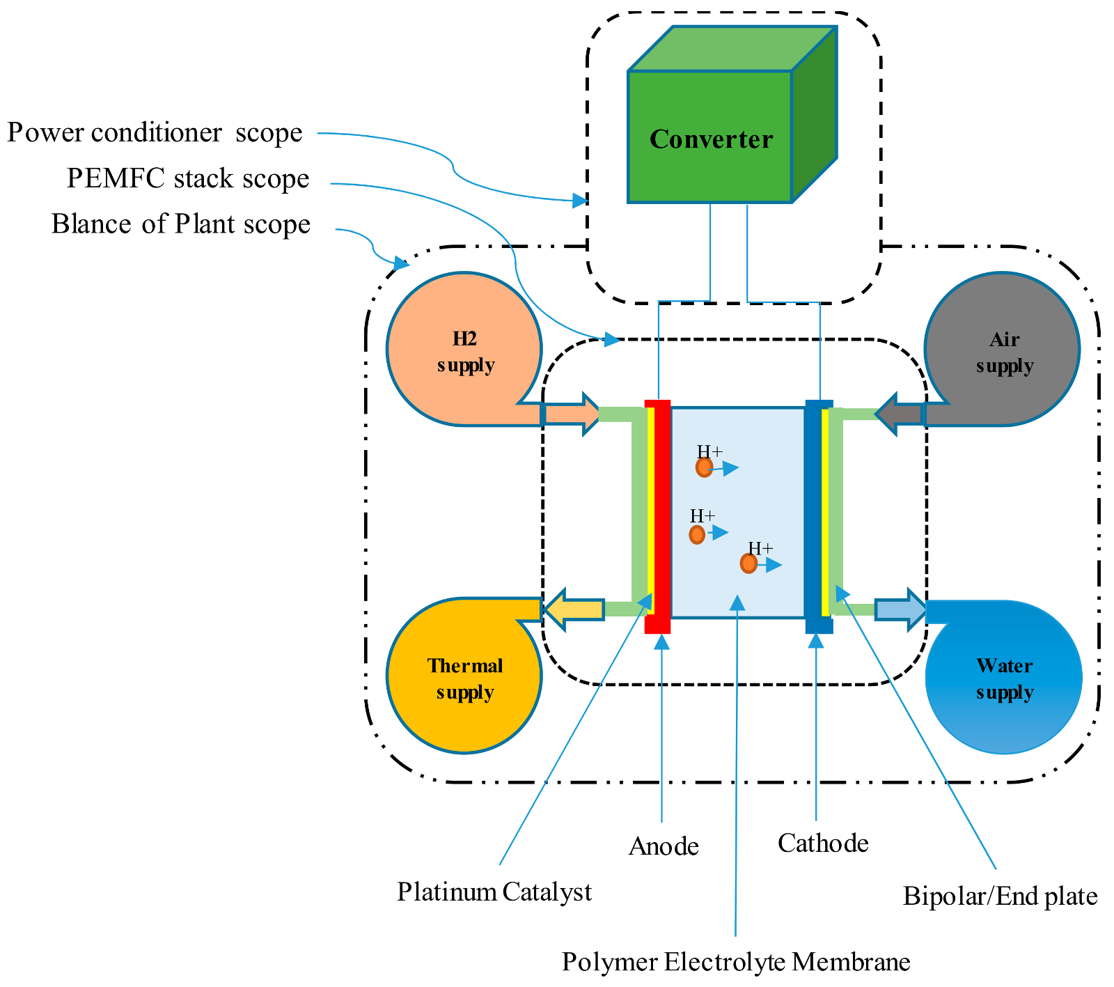
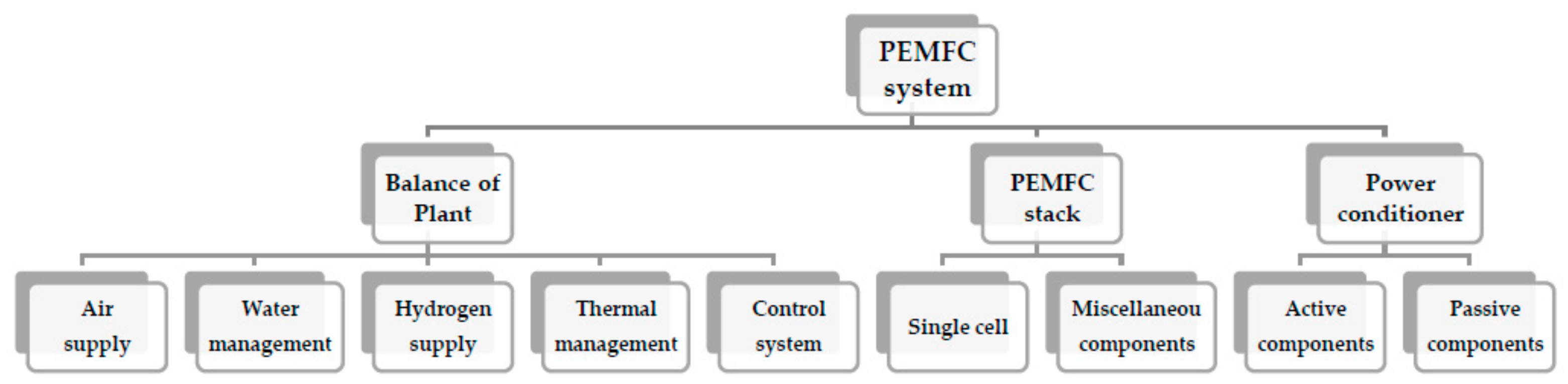
2. The Model of Proton Exchange Membrane Fuel Cell (PEMFC)
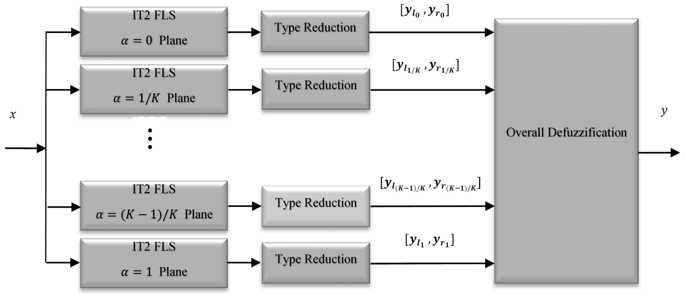
3. General Type-2 Fuzzy Systems
4. Failure Mode and Effect Analysis (FMEA)
General Type-II Fuzzy Based Failure Mode and Effect Analysis
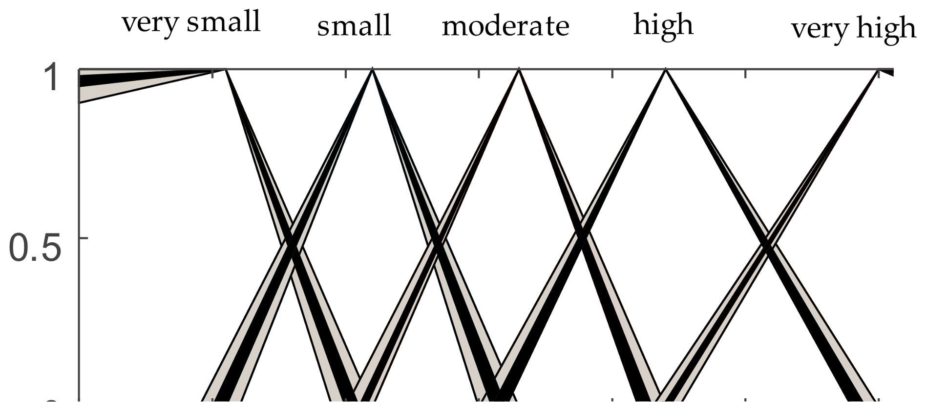
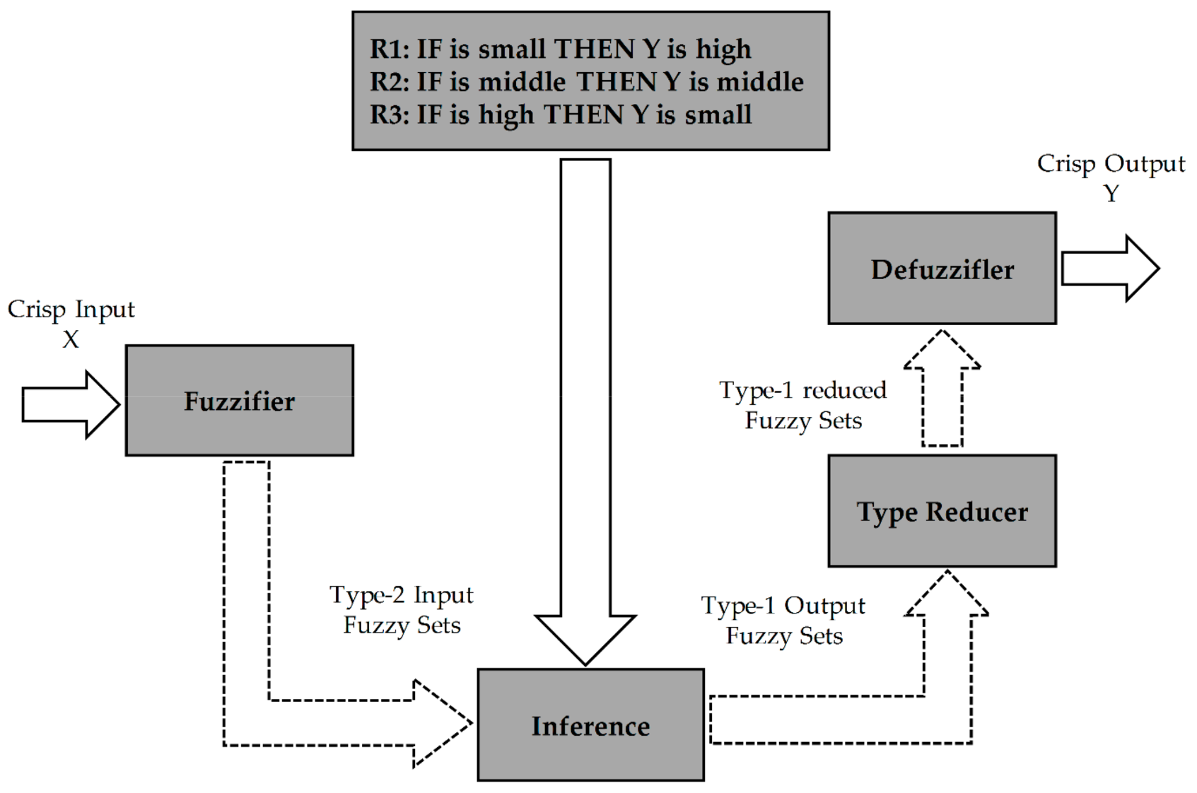
- IF “likelihood is improbable” & “severity is minor” & “detectability is very high”, THEN “RPN is very small”.
- IF “likelihood is occasional” & “severity is major” & “detectability is remote”, THEN “RPN is medium”.
- IF “likelihood is frequent” & “severity is major” & “detectability is never”, THEN “RPN is high”.
5. Results and Discussion
6. Conclusions
Author Contributions
Conflicts of Interest
References
- Yuan, X.Z.; Li, H.; Zhang, S.; Martin, J.; Wang, H. A review of polymer electrolyte membrane fuel cell durability test protocols. J. Power Sources 2011, 196, 9107–9116. [Google Scholar] [CrossRef]
- Barbir, F. PEM Fuel Cells: Theory and Practice; Academic Press: Cambridge, MA, USA, 2013; ISBN 9780123877109. [Google Scholar]
- Zhang, J. PEM Fuel Cell Electrocatalysts and Catalyst Layers: Fundamentals and Applications; Springer: Berlin, Germany, 2008; ISBN 9781848009356. [Google Scholar]
- Zhang, J.; Zhang, H.; Wu, J.; Zhang, J. PEM Fuel Cell Testing and Diagnosis; Elsevier: Amsterdam, The Netherlands, 2013; ISBN 9780444536884. [Google Scholar]
- Jayakumar, A.; Sethu, S.P.; Ramos, M.; Robertson, J.; Al-Jumaily, A. A technical review on gas diffusion, mechanism and medium of PEM fuel cell. Ionics (Kiel) 2015, 21, 1–18. [Google Scholar] [CrossRef]
- Zhou, D.; Wang, H.; Blaabjerg, F.; Kær, S.K.; Blom-hansen, D. System-level Reliability Assessment of Power Stage in Fuel Cell Application. In Proceedings of the 2016 IEEE Energy Conversion Congress and Exposition (ECCE), Milwaukee, WI, USA, 18–22 September 2016. [Google Scholar]
- Lee, S.; Zhou, D.; Wang, H. Reliablity assessment of fuel cell system—A framework for quantitative approach. In Proceedings of the 2016 IEEE Energy Conversion Congress and Exposition (ECCE), Milwaukee, WI, USA, 18–22 September 2016. [Google Scholar] [CrossRef]
- Ma, K.; Wang, H.; Blaabjerg, F. New approaches to reliability assessment: Using physics-of-failure for prediction and design in power electronics systems. IEEE Power Electron. Mag. 2016, 3, 28–41. [Google Scholar] [CrossRef]
- Huai, W.; Liserre, M.; Blaabjerg, F.; De Place Rimmen, P.; Jacobsen, J.B.; Kvisgaard, T.; Landkildehus, J. Transitioning to physics-of-failure as a reliability driver in power electronics. IEEE J. Emerg. Sel. Top. Power Electron. 2014, 2, 97–114. [Google Scholar] [CrossRef]
- Rafie, M.; Samimi Namin, F. Prediction of subsidence risk by FMEA using artificial neural network and fuzzy inference system. Int. J. Min. Sci. Technol. 2015, 25, 655–663. [Google Scholar] [CrossRef]
- Ahn, J.; Noh, Y.; Park, S.H.; Choi, B., II; Chang, D. Fuzzy-based failure mode and effect analysis (FMEA) of a hybrid molten carbonate fuel cell (MCFC) and gas turbine system for marine propulsion. J. Power Sources 2017, 364, 226–233. [Google Scholar] [CrossRef]
- Casson Moreno, V.; Cozzani, V. Integrated hazard identification within the risk management of industrial biological processes. Saf. Sci. 2018, 103, 340–351. [Google Scholar] [CrossRef]
- Dunjó, J.; Fthenakis, V.; Vílchez, J.A.; Arnaldos, J. Hazard and operability (HAZOP) analysis. A literature review. J. Hazard. Mater. 2010, 173, 19–32. [Google Scholar] [CrossRef] [PubMed]
- Kang, J.; Sun, L.; Sun, H.; Wu, C. Risk assessment of floating offshore wind turbine based on correlation-FMEA. Ocean Eng. 2017, 129, 382–388. [Google Scholar] [CrossRef]
- Gerbec, M.; Jovan, V.; Petrovčič, J. Operational and safety analyses of a commercial PEMFC system. Int. J. Hydrog. Energy 2008, 33, 4147–4160. [Google Scholar] [CrossRef]
- Jayakumar, A.; Ramos, M.; Al-Jumaily, A. A Novel Fuzzy Schema to Control the Temperature and Humidification of PEM Fuel Cell System. In Proceedings of the ASME 2015 13th International Conference on Fuel Cell Science, Engineering and Technology, San Diego, CA, USA, 28 June–2 July 2015; p. V001T06A005. [Google Scholar]
- Hora, S.C. Aleatory and epistemic uncertainty in probability elicitation with an example from hazardous waste management. Reliab. Eng. Syst. Saf. 1996, 54, 217–223. [Google Scholar] [CrossRef]
- Zadeh, L.A. The concept of a linguistic variable and its application to approximate reasoning—I. Inf. Sci. 1975, 8, 199–249. [Google Scholar] [CrossRef]
- Khooban, M.H.; Liaghat, A. A time-varying strategy for urban traffic network control: A fuzzy logic control based on an improved black hole algorithm. Int. J. Bio-Inspired Comput. 2017, 10, 33–42. [Google Scholar] [CrossRef]
- Khooban, M.H.; Niknam, T.; Sha-Sadeghi, M. A time-varying general type-II fuzzy sliding mode controller for a class of nonlinear power systems. J. Intell. Fuzzy Syst. 2016, 30, 2927–2937. [Google Scholar] [CrossRef]
- Khooban, M.H.; Niknam, T.; Sha-Sadeghi, M. Speed control of electrical vehicles: A time-varying proportional–integral controller-based type-2 fuzzy logic. IET Sci. Meas. Technol. 2016, 10, 185–192. [Google Scholar] [CrossRef]
- Khooban, M.H.; Vafamand, N.; Liaghat, A.; Dragicevic, T. An optimal general type-2 fuzzy controller for Urban Traffic Network. ISA Trans. 2017, 66, 335–343. [Google Scholar] [CrossRef] [PubMed]
- Tavana, M.R.; Khooban, M.-H.; Niknam, T. Adaptive PI controller to voltage regulation in power systems: STATCOM as a case study. ISA Trans. 2017, 66, 325–334. [Google Scholar] [CrossRef] [PubMed]
- Khooban, M.H.; Niknam, T. A new and robust control strategy for a class of nonlinear power systems: Adaptive general type-II fuzzy. Proc. Inst. Mech. Eng. Part I J. Syst. Control Eng. 2015, 229, 517–528. [Google Scholar] [CrossRef]
- Khooban, M.H.; Ghaemi, M.; Hosseini-Sani, S.K. Direct adaptive general type-2 fuzzy control for a class of uncertain non-linear systems. IET Sci. Meas. Technol. 2014, 8, 518–527. [Google Scholar] [CrossRef]
- Khooban, M.-H.; Niknam, T.; Shasadeghi, M.; Dragicevic, T.; Blaabjerg, F. Load Frequency Control in Microgrids Based on a Stochastic Non-Integer Controller. IEEE Trans. Sustain. Energy 2017, 9, 853–861. [Google Scholar] [CrossRef]
- Khooban, M.-H.; Dragicevic, T.; Blaabjerg, F.; Delimar, M. Shipboard Microgrids: A Novel Approach to Load Frequency Control. IEEE Trans. Sustain. Energy 2017, 9, 843–852. [Google Scholar] [CrossRef]
- Khooban, M.H.; ShaSadeghi, M.; Niknam, T.; Blaabjerg, F. Analysis, control and design of speed control of electric vehicles delayed model: Multi-objective fuzzy fractional-order P I λ D μ controller. IET Sci. Meas. Technol. 2017, 11, 249–261. [Google Scholar] [CrossRef]
- Abadi, D.N.M.; Khooban, M.H. Design of optimal Mamdani-type fuzzy controller for nonholonomic wheeled mobile robots. J. King Saud Univ. Eng. Sci. 2015, 27, 92–100. [Google Scholar] [CrossRef]
- Khooban, M.H.; Niknam, T.; Dehghani, M.; Blaabjerg, F. Free chattering hybrid sliding mode control for a class of non-linear systems: Electric vehicles as a case study. IET Sci. Meas. Technol. 2016, 10, 776–785. [Google Scholar] [CrossRef]
- Khooban, M.H.; Vafamand, N.; Niknam, T. T–S fuzzy model predictive speed control of electrical vehicles. ISA Trans. 2016, 64, 231–240. [Google Scholar] [CrossRef] [PubMed]
- Khooban, M.H.; Niknam, T.; Blaabjerg, F.; Dragičević, T. A new load frequency control strategy for micro-grids with considering electrical vehicles. Electr. Power Syst. Res. 2017, 143, 585–598. [Google Scholar] [CrossRef]
- Niknam, T.; Khooban, M.H. Fuzzy sliding mode control scheme for a class of non-linear uncertain chaotic systems. IET Sci. Meas. Technol. 2013, 7, 249–255. [Google Scholar] [CrossRef]
- Niknam, T.; Khooban, M.H.; Kavousifard, A.; Soltanpour, M.R. An optimal type II fuzzy sliding mode control design for a class of nonlinear systems. Nonlinear Dyn. 2014, 75, 73–83. [Google Scholar] [CrossRef]
- Liu, F. An efficient centroid type-reduction strategy for general type-2 fuzzy logic system. Inf. Sci. 2008, 178, 2224–2236. [Google Scholar] [CrossRef]
- Karnik, N.N.; Mendel, J.M. Type-2 fuzzy logic systems: Type-reduction. In SMC’98 Conference Proceedings, Proceedings of the 1998 IEEE International Conference on Systems, Man, and Cybernetics, San Diego, CA, USA, 14 October 1998; Cat. No. 98CH36218; IEEE: Piscataway, NJ, USA, 1998; Volume 2, pp. 2046–2051. [Google Scholar]
- Karnik, N.N.; Mendel, J.M. Centroid of a type-2 fuzzy set. Inf. Sci. 2001, 132, 195–220. [Google Scholar] [CrossRef]
- Mendel, J.M.; Feilong, L.; Daoyuan, Z. α-Plane Representation for Type-2 Fuzzy Sets: Theory and Applications. IEEE Trans. Fuzzy Syst. 2009, 17, 1189–1207. [Google Scholar] [CrossRef]
- Feili, H.R.; Akar, N.; Lotfizadeh, H.; Bairampour, M.; Nasiri, S. Risk analysis of geothermal power plants using Failure Modes and Effects Analysis (FMEA) technique. Energy Convers. Manag. 2013, 72, 69–76. [Google Scholar] [CrossRef]
- Colli, A. Failure mode and effect analysis for photovoltaic systems. Renew. Sustain. Energy Rev. 2015, 50, 804–809. [Google Scholar] [CrossRef]
- Narayanagounder, S.; Gurusami, K. A New Approach for Prioritization of Failure Modes in Design FMEA using ANOVA. World Acad. Sci. Eng. Technol. 2009, 3, 524–531. [Google Scholar]
- Carlson, C. Effective FMEAs: Achieving Safe, Reliable, and Economical Products and Processes Using Failure Mode and Effects Analysis; John Wiley & Sons: Hoboken, NJ, USA, 2012. [Google Scholar]
- Fattahi, R.; Khalilzadeh, M. Risk evaluation using a novel hybrid method based on FMEA, extended MULTIMOORA, and AHP methods under fuzzy environment. Saf. Sci. 2018, 102, 290–300. [Google Scholar] [CrossRef]
- Mao, L.; Jackson, L.; Davies, B. Investigation of PEMFC fault diagnosis with consideration of sensor reliability. Int. J. Hydrogen Energy 2017. [Google Scholar] [CrossRef]
- Mao, L.; Jackson, L.; Dunnett, S. Fault Diagnosis of Practical Polymer Electrolyte Membrane (PEM) Fuel Cell System with Data-driven Approaches. Fuel Cells 2017, 17, 247–258. [Google Scholar] [CrossRef]
- Carlson, C.S. Effective FMEAs; John Wiley & Sons, Inc.: Hoboken, NJ, USA, 2012; ISBN 9781118312575. [Google Scholar]
- Adar, E.; İnce, M.; Karatop, B.; Bilgili, M.S. The risk analysis by failure mode and effect analysis (FMEA) and fuzzy-FMEA of supercritical water gasification system used in the sewage sludge treatment. J. Environ. Chem. Eng. 2017, 5, 1261–1268. [Google Scholar] [CrossRef]
- Dağsuyu, C.; Göçmen, E.; Narlı, M.; Kokangül, A. Classical and fuzzy FMEA risk analysis in a sterilization unit. Comput. Ind. Eng. 2016, 101, 286–294. [Google Scholar] [CrossRef]


| System | Subsystem | Component | ID | Part |
|---|---|---|---|---|
| Proton Exchange Membrane Fuel Cell (PEMFC) | Balance of Plant | Air supply/management | 1 | Compressor/Blower |
| 2 | Air Filter | |||
| 3 | Expander | |||
| 4 | Air connectors | |||
| Water supply/management | 5 | Water separator & filter | ||
| 6 | Water valve | |||
| 7 | Water tank | |||
| 8 | Water pump | |||
| 9 | Water connectors | |||
| 10 | Humidifier/HE | |||
| Thermal supply/management | 11 | Fan | ||
| 12 | Coolant pump | |||
| 13 | Condenser | |||
| 14 | Thermal connectors | |||
| 15 | Anode cooler/HE | |||
| 16 | Radiator/HE | |||
| Hydrogen supply/management | 17 | H2 valves | ||
| 18 | H2 tank | |||
| 19 | H2 reformer/purification | |||
| 20 | H2 connectors | |||
| Control system | 21 | Electrical control system | ||
| 22 | Mechanical control system | |||
| PEMFC stack | Single Cell | 23 | MEA | |
| 24 | Current collector plate | |||
| 25 | Flow field plate | |||
| 26 | End plate | |||
| 27 | Sealing materials | |||
| miscellaneous components | 28 | Bipolar plates | ||
| 29 | Cooling plates | |||
| 30 | End plates | |||
| 31 | Bolts | |||
| 32 | Gaskets | |||
| Power conditioner | Passive components electrical | 33 | Capacitors | |
| 34 | Transformer | |||
| 35 | Inductor | |||
| 36 | PCB | |||
| Active components electrical | 37 | MOSFETs | ||
| 38 | Diodes |
| Ranking | Probability | Description |
|---|---|---|
| 1 | 10−5 | Improbable—unlikely to occur at all |
| 2 | 10−4 | Remote—once in 100 to 1000 years on one ship |
| 3 | 10−3 | Rare—once in 10 to 100 years on one ship |
| 4 | 10−2 | Occasional—once in 1 to 10 years on one ship |
| 5 | 10−1 | Frequent—once in one year on one ship |
| Ranking | Criteria | Description |
|---|---|---|
| 1 | Very high | The disturbance will cause an alert or will initiate a shut down. |
| 2 | High | The disturbance is detectable according to the deviation of the system. |
| 3 | Low | The disturbance is not detectable by a sensor. |
| 4 | Remote | The disturbance is not physically detectable. |
| 5 | Never | The disturbance is not detectable by any methods. |
| Ranking | Consequence | Human | Environment | Asset |
|---|---|---|---|---|
| 1 | Minor | No injury | Negligible pollution | Less than 20,000 US$ (onboard repair required) |
| 2 | Significant | Single or minor injury | Detectable pollution | Less than 200,000 US$ (port-stay repair required) |
| 3 | Moderate | Multiple or severe injury | Major pollution (short-term disruption of the ecosystem) | Less than 2 MUS$ (yard repair required) |
| 4 | Major | Single fatality or multiple severe injuries | Severe pollution (medium-term disruption of the ecosystem) | Less than 20 MUS$ (yard repair required) |
| 5 | Catastrophic | Multiple fatalities | Uncontrolled pollution | Less than 200 MUS$ (total loss) |
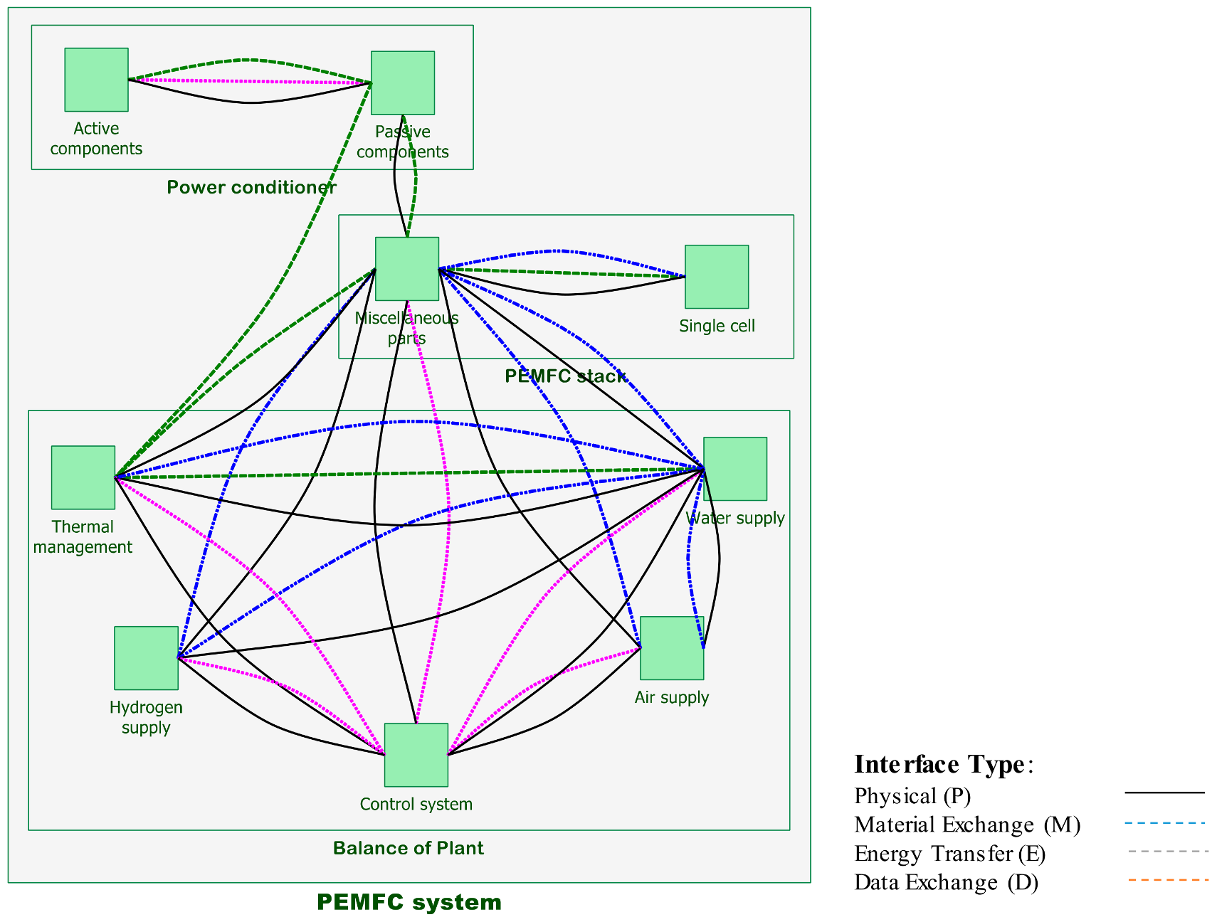
| PEMFC Components | Air S/M | Water S/M | Thermal S/M | Hydrogen S/M | Control System | Single Cell | MC | PCE | ACE |
|---|---|---|---|---|---|---|---|---|---|
| Air supply/management | PM1 | PD1 | PM1 | ||||||
| Watersupply/management | PM1 | PME1 | PM1 | PD1 | PM1 | ||||
| Thermal supply/management | PME1 | PD1 | PE1 | ||||||
| Hydrogen supply/management | PE1 | PD1 | PM1 | ||||||
| Control system | PD1 | PD1 | PD1 | PD1 | PD1 | ||||
| Single cell | PE1 | ||||||||
| Miscellaneous Components (MC) | PM1 | PM1 | PE1 | PM1 | PME1 | PE1 | |||
| Passive Components Electrical (PCE) | E2 | PE1 | PED1 | ||||||
| Active Components Electrical (ACE) | PED1 |
| Item | Function | Failure | Cause | Effect | S | O | D | Rincon | RPN_T1 | RPN_T2 |
|---|---|---|---|---|---|---|---|---|---|---|
| Air supply/management | Supply and management of Air for work of PEMFC stack | Contamination, Blockage, Fractured, Leaking | Restricted filter, Weak valves/bonding, Improper adjustment. | Does not fit, Leaks, Operation impaired. | 1 | 2 | 2 | 4 | 12 | 10.5 |
| Water supply/management | Create humidifier management for Inlet Hydrogen and Air, as well as gather and management, produced water stack | Corrosion, Deposits, Blockage, Leaking, Improper adjustment, Sludge buildup. | Weak filter/valve, Use of defective material, Humidity, High temperature. | Damages equipment, Leaks, Excessive effort required, Does not match. | 1 | 2 | 3 | 6 | 14 | 15.5 |
| Thermal supply/management | Reduce and management of the fuel cell stack and power conditioner temperature | Swells, Deposits, Erosion, Fractured, Frayed, Leaking, Loosened, Sludge buildup, Overheat. | Thermal Shock/Fatigue, Improper alignment, Poor bonding, Material instability, Blockage. | Damages equipment, Erratic Operation, Increased yield loss, Leaks, Unstable, Thermal event. | 2 | 3 | 4 | 24 | 33.4 | 29.3 |
| Hydrogen supply/management | Hydrogen supply, hydrogen purification, hydrogen riching | Overpressure, Fractured, Contamination, Inadequate support (structural), Leaking. | Cracking/Stress Induced Hydrogen, Weak valve/bonding, Use of defective material, Restricted filter. | Operation impaired, Does not fit, Leaks, Does not match. | 2 | 3 | 2 | 12 | 12.9 | 13.1 |
| Control system | Control and monitor the all of system and tasks of each component | Mechanical and electrical Failures, Contact damage, Distortion, Mis-alignment, Mislabeled, No signal, Shock failure, Signal inadequate, signal intermittently. | Fracture, Excessive heat, Excessive loading, Excessive tension, Extreme operating speeds, Foreign object. | Unstable, Control impaired, Thermal event, Rework/Repairs, Regulatory non-compliance, Increased yield loss, Erratic Operation, Causes excessive tool wear. | 5 | 4 | 3 | 60 | 93.8 | 95.4 |
| Single cell | Convert the chemical energy to electrical energy through chemical reactions | Cavitation, Corrosion, Deformed, Deposits, Erosion, Extruded, Metallurgical Failures, Oxidized, Material unstable, Electric Current. | Chemical oxidation, Corrosion Under Insulation, Excessive heat, Excessive tension, Humidity, Material instability. | Non-production, Damage, Increased yield loss, Leaks, Unstable, Overheat. | 3 | 4 | 4 | 48 | 60 | 59.5 |
| Miscellaneous components | Create conditions to improve produce electricity that dependents to the number of single cells | Blockage, Deformed, Embrittlement, Extruded, Fractured, Frayed, Inadequate support (structural), Leaking, Loosened, Slips. | Excessive heat/condensation, Material instability, Use of defective material, Thermal Fatigue, Warped and poor sealing surfaces. | Faultiness in functions, Causes excessive tool wear, Damages equipment, Increased yield loss, Leaks, Replace/Repairs, Scrap. | 2 | 3 | 3 | 18 | 25.3 | 22.8 |
| Active Electrical Components | Switching, Strengthen, Rectification, Control and regulate voltage/current. | Failure to switching, Non- amplification, Voltage and current fluctuations, Overloading, Contact damage. | High voltage/current, Short/open circuit, High temperature, Improper positioning, Improper specification. | Does not fit, Does not connect, Operation impaired. | 1 | 3 | 2 | 6 | 14 | 16.2 |
| Passive Electrical Components | Storage, Filtering, Tuning circuit, Conductor, stabilizer, Transfers power voltage level, Provide electrical isolation, Mechanically support and electrically connects electronic components. | Improper pieces selection, Voltage and current fluctuations, Inadequate support (structural), Open circuit, Overloading, Short circuit. | Short/open circuit, Fracture, Incorrect installation, Excessive loading/condensation/heat, Improper adjustment. | Yield loss, Does not match, Replace/Repairs components, Operation impaired, Thermal event. | 3 | 4 | 2 | 24 | 35.1 | 33.9 |
© 2018 by the authors. Licensee MDPI, Basel, Switzerland. This article is an open access article distributed under the terms and conditions of the Creative Commons Attribution (CC BY) license (http://creativecommons.org/licenses/by/4.0/).
Share and Cite
Bahrebar, S.; Blaabjerg, F.; Wang, H.; Vafamand, N.; Khooban, M.-H.; Rastayesh, S.; Zhou, D. A Novel Type-2 Fuzzy Logic for Improved Risk Analysis of Proton Exchange Membrane Fuel Cells in Marine Power Systems Application. Energies 2018, 11, 721. https://doi.org/10.3390/en11040721
Bahrebar S, Blaabjerg F, Wang H, Vafamand N, Khooban M-H, Rastayesh S, Zhou D. A Novel Type-2 Fuzzy Logic for Improved Risk Analysis of Proton Exchange Membrane Fuel Cells in Marine Power Systems Application. Energies. 2018; 11(4):721. https://doi.org/10.3390/en11040721
Chicago/Turabian StyleBahrebar, Sajjad, Frede Blaabjerg, Huai Wang, Navid Vafamand, Mohammad-Hassan Khooban, Sima Rastayesh, and Dao Zhou. 2018. "A Novel Type-2 Fuzzy Logic for Improved Risk Analysis of Proton Exchange Membrane Fuel Cells in Marine Power Systems Application" Energies 11, no. 4: 721. https://doi.org/10.3390/en11040721
APA StyleBahrebar, S., Blaabjerg, F., Wang, H., Vafamand, N., Khooban, M.-H., Rastayesh, S., & Zhou, D. (2018). A Novel Type-2 Fuzzy Logic for Improved Risk Analysis of Proton Exchange Membrane Fuel Cells in Marine Power Systems Application. Energies, 11(4), 721. https://doi.org/10.3390/en11040721