Harmonic Analysis of Single-Phase Neutral-Point-Clamped Cascaded Inverter in Advanced Traction Power Supply System Based on the Big Triangular Carrier Equivalence Method


Abstract
:1. Introduction
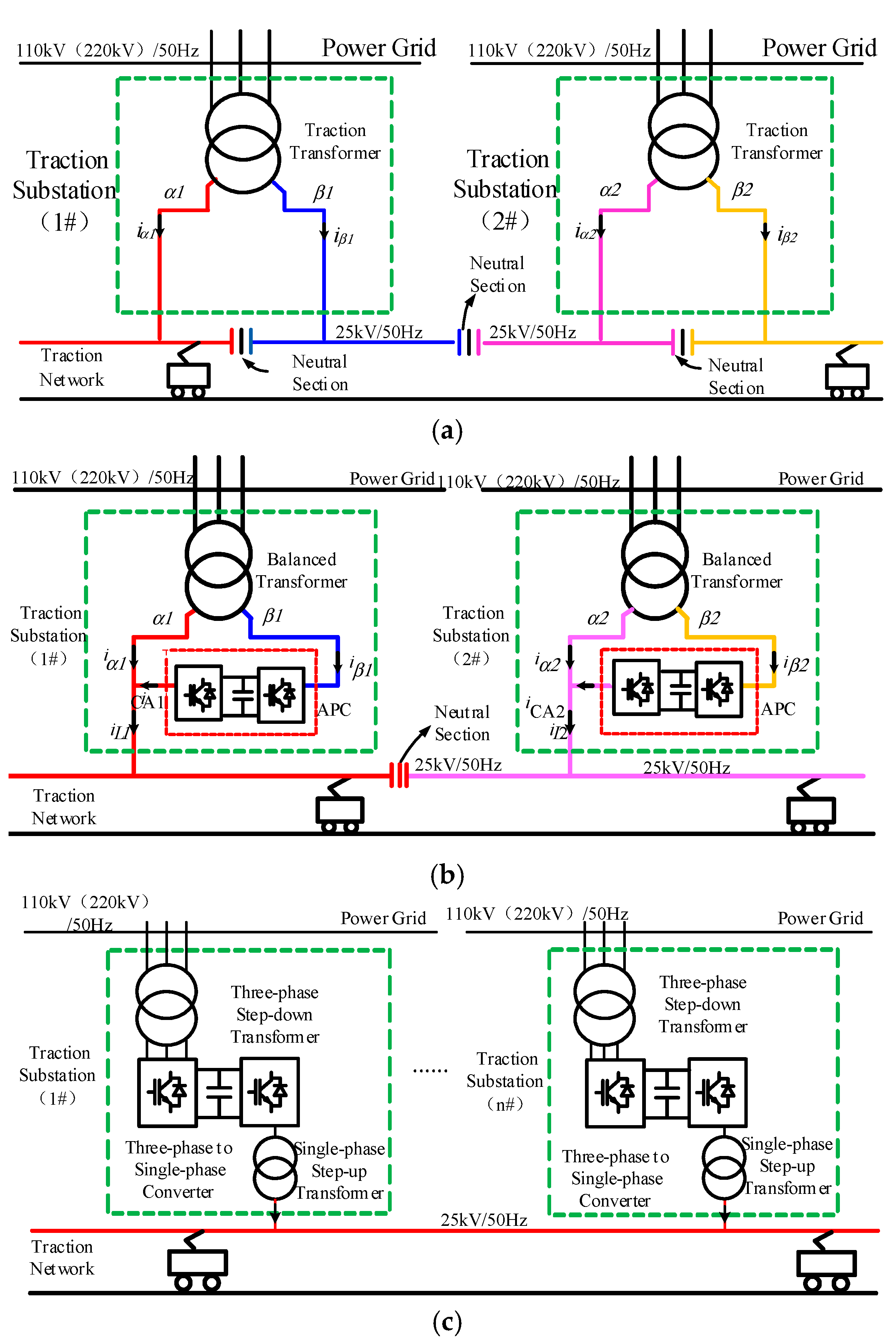
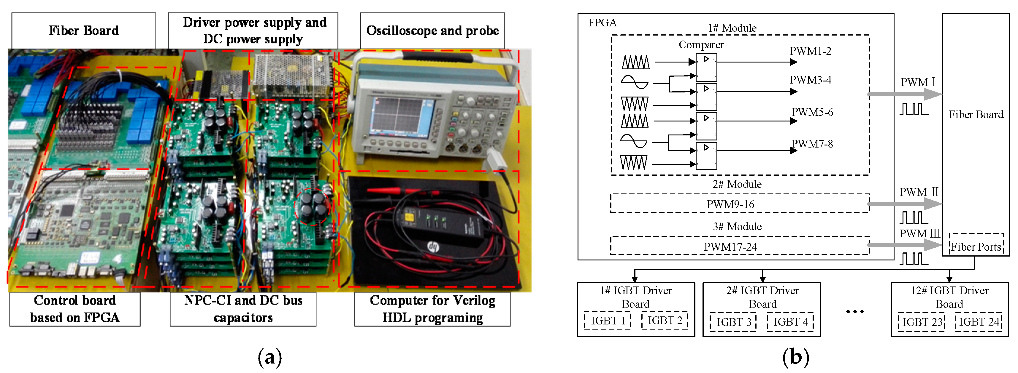
2. Configuration
3. Big Triangular Carrier Equivalence Method and Modulation of NPC Cascaded Inverter
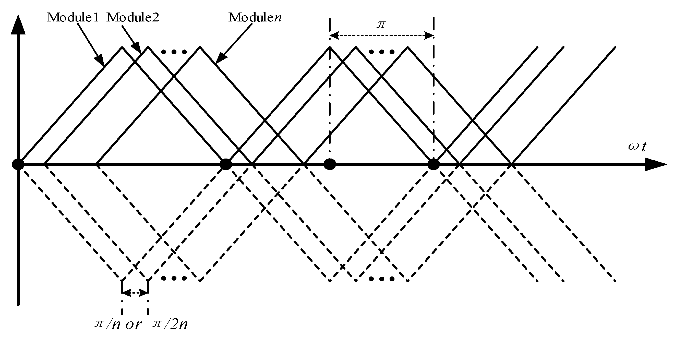
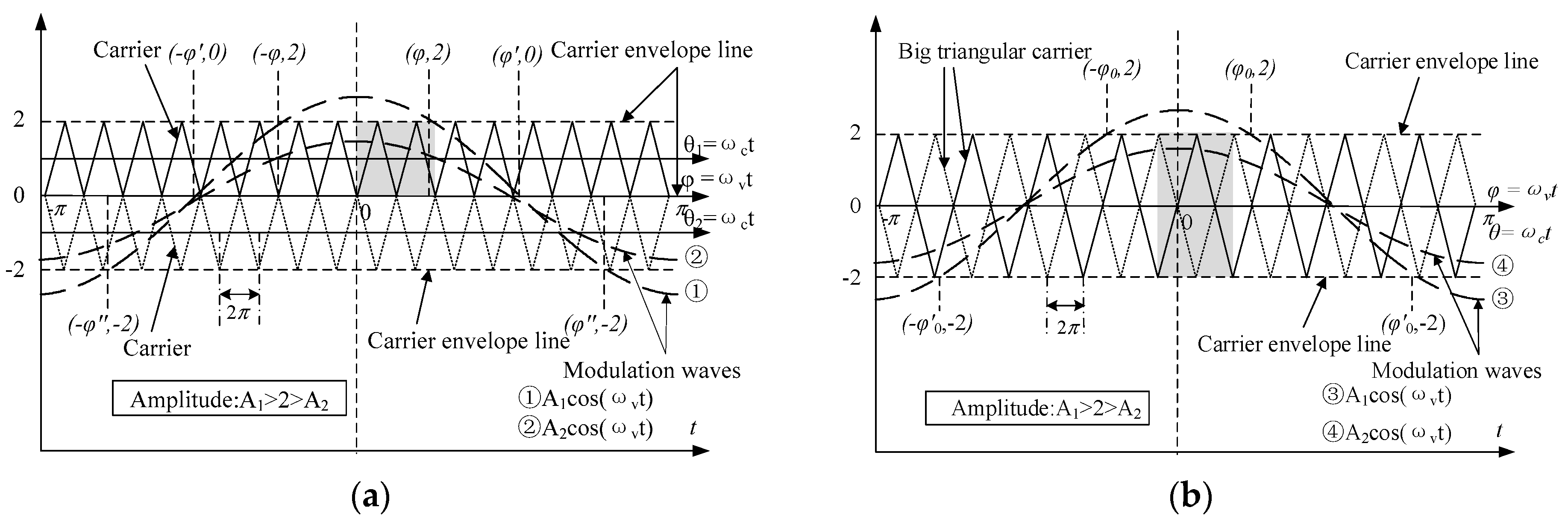
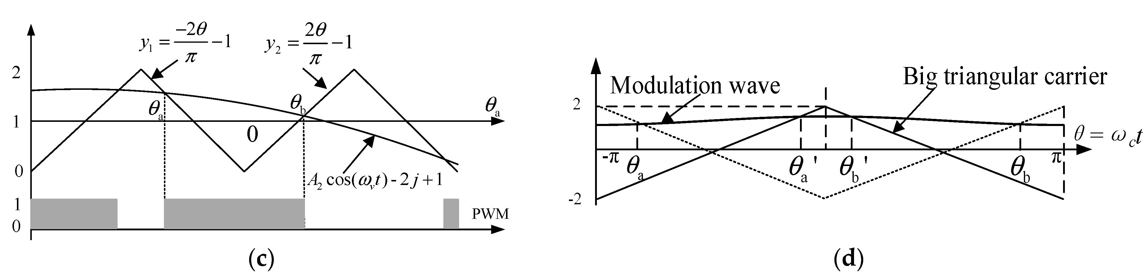
3.1. Big Triangular Carrier Equivalence Method
3.2. Double Coordinate System
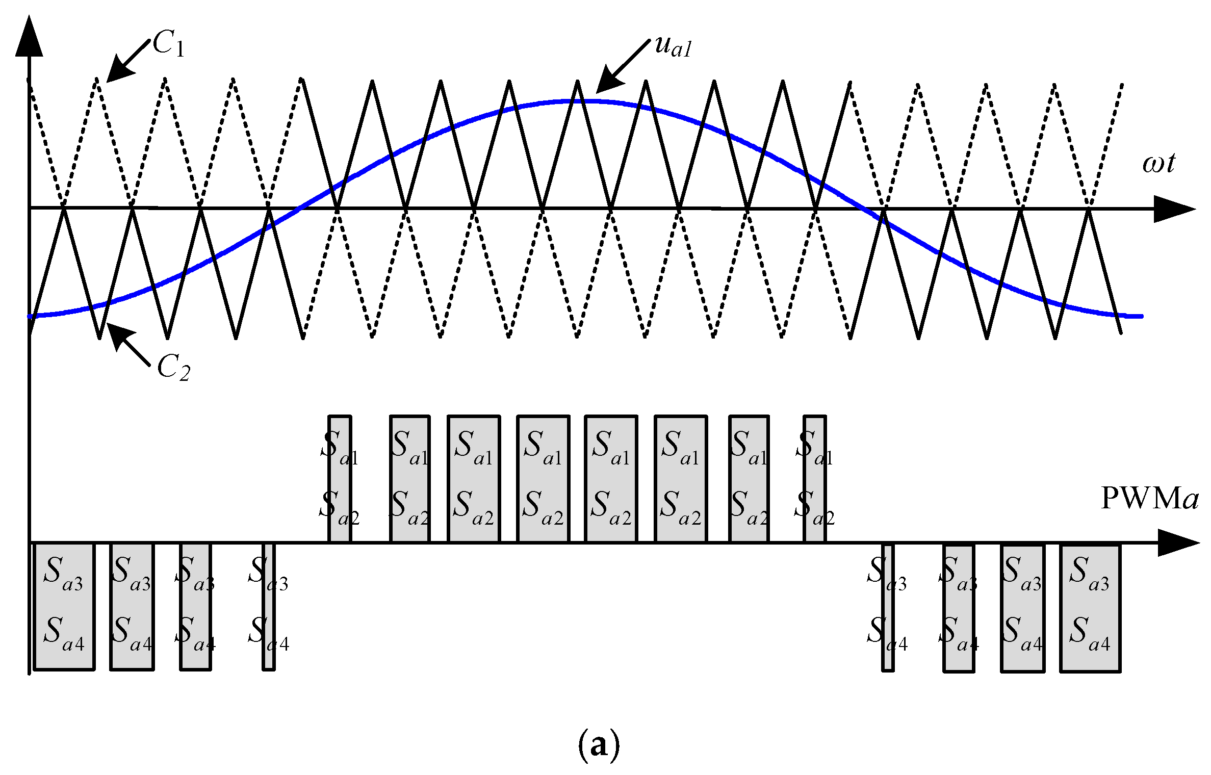
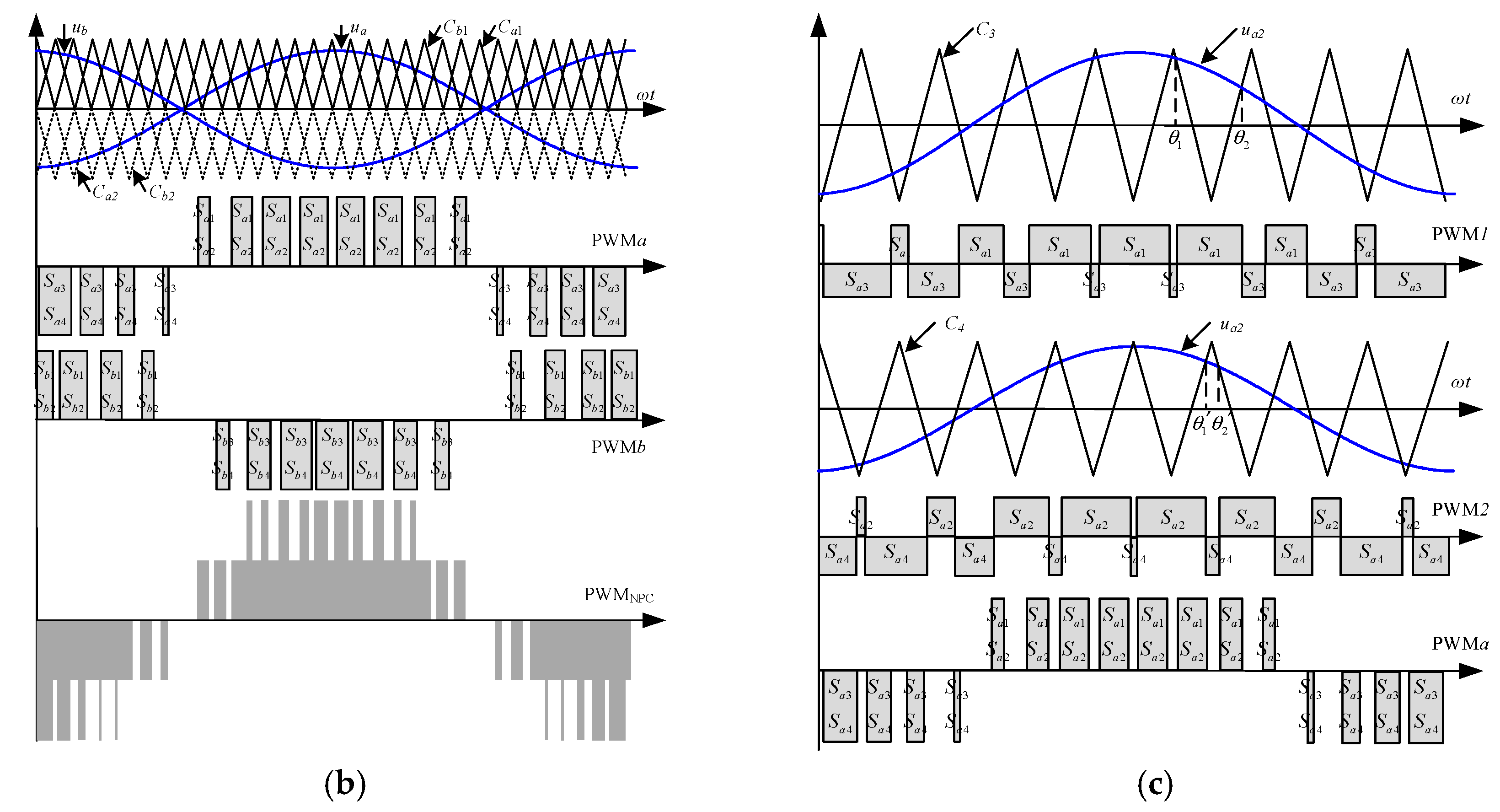
3.3. Modulation of NPC Cascaded Inverter
4. Output Spectrum of Single-Phase NPC Cascaded Inverter
4.1. Derivation of Switching Function
4.2. Derivation of Output Spectrum of CPSPOD-SPWM
5. Simulation and Experiment
5.1. Simulation
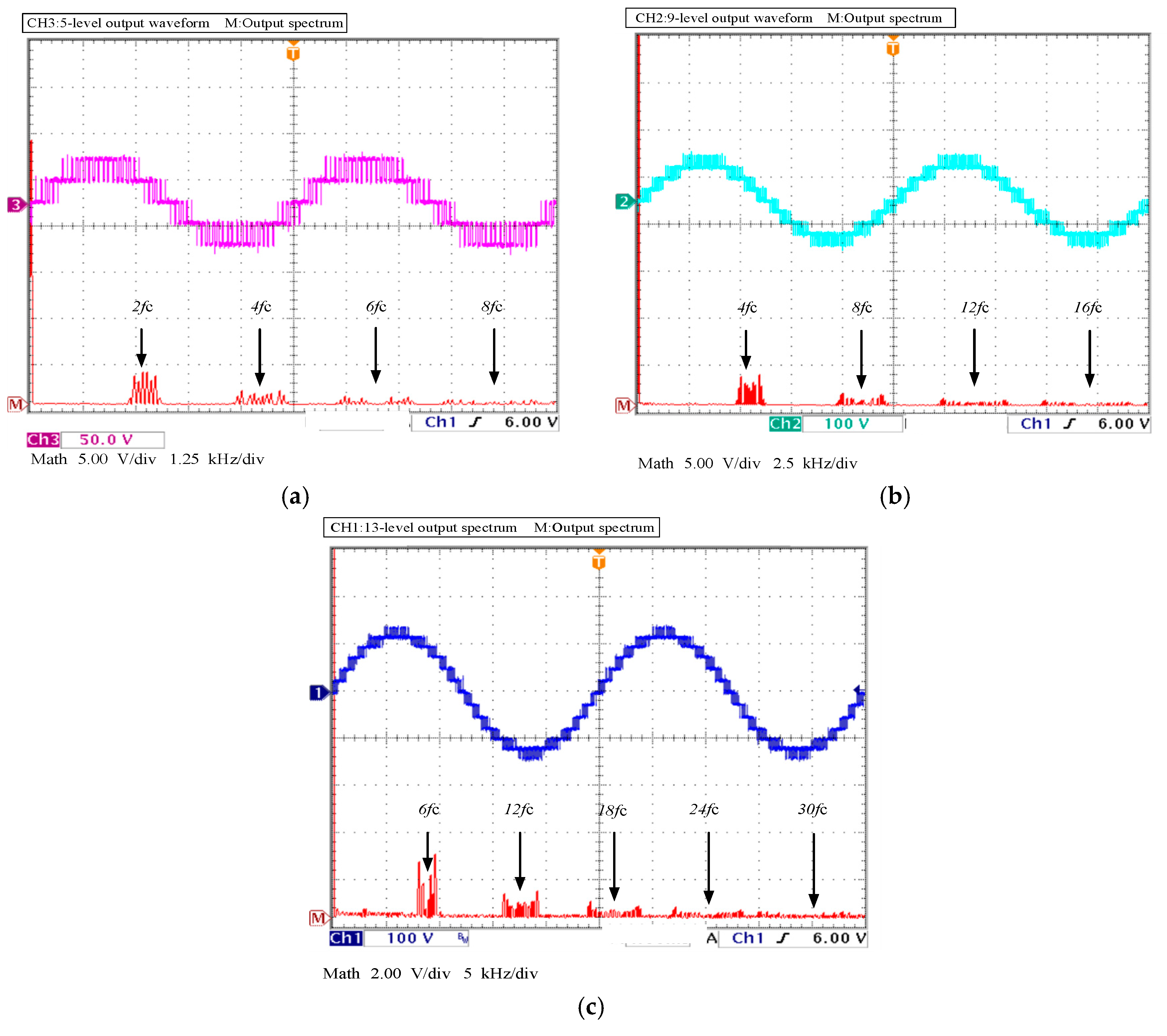
5.2. Low Power Experiment
6. Conclusions
- (1)
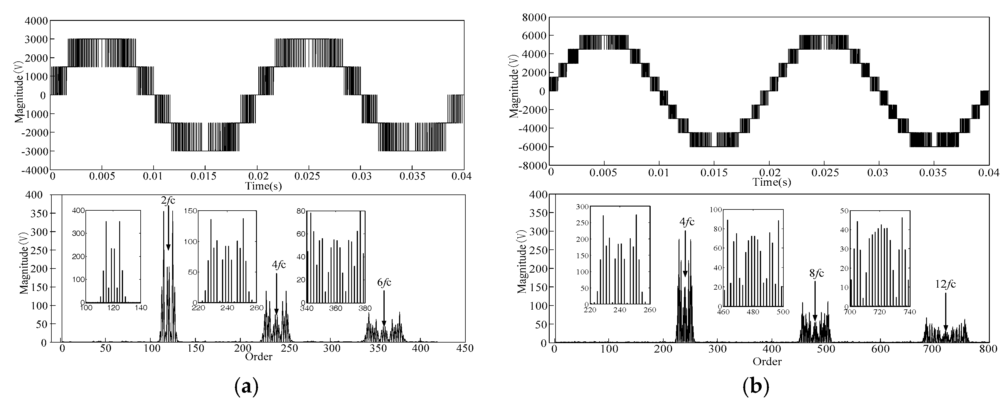
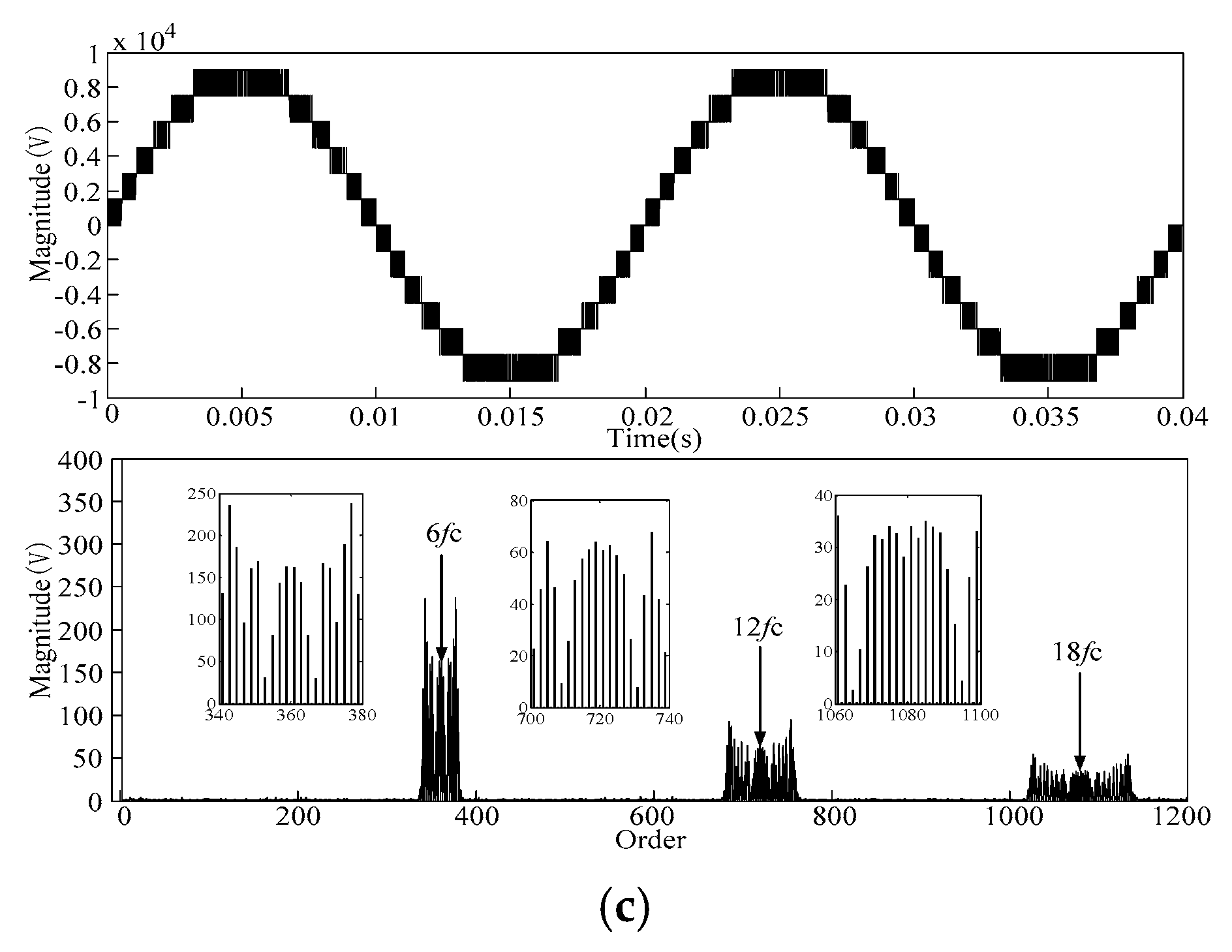
- The equivalent switching frequency of the output voltage increases by adding a certain number of cascaded single-phase NPC module-based cascaded structures, and the frequency of the odd harmonics which exist in the side frequency band of mainly is 2N (4N, …) times higher than the carrier frequency, where N represents the number of NPC modules;
- (2)
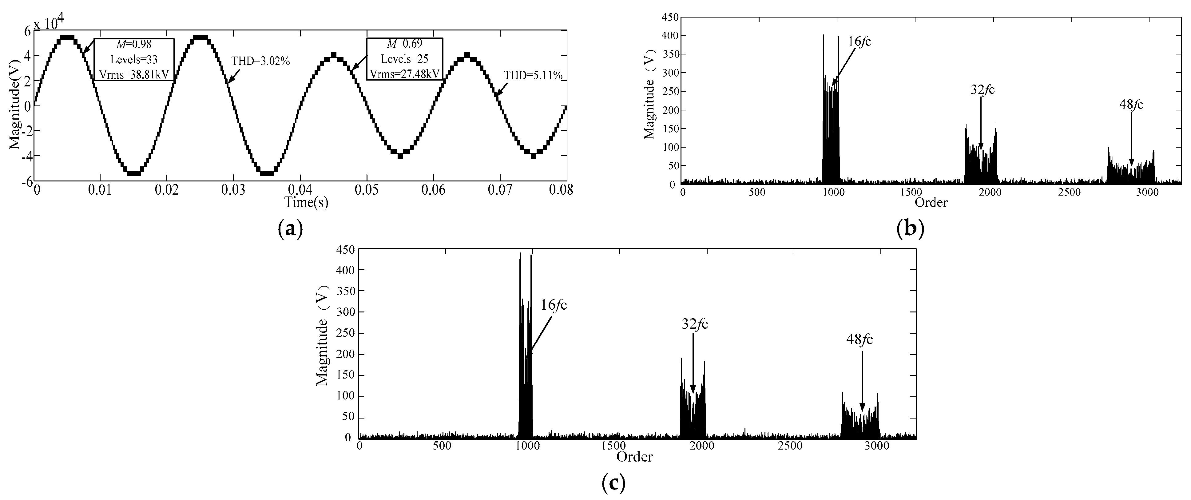
- The output spectrum barely contains the harmonics of the carrier frequency or lower order harmonics. Meanwhile, the output voltage becomes better regulated and the THD becomes much lower with the increasing number of cascaded modules.
- (3)
- The method proposed in the paper to analyze the harmonic characteristic is proved to be correct by simulations and experiments. The harmonic characteristics of an advanced traction power supply system based on a single phase NPC cascaded inverter analyzed in this paper provides a theoretical way to avoid railway traction network resonance.
Acknowledgments
Author Contributions
Conflicts of Interest
References
- Nabae, A.; Takahashi, I.; Akagi, H. A New Neutral-Point-Clamped PWM Inverter. IEEE Trans. Ind. Appl. 1981, IA-17, 518–523. [Google Scholar] [CrossRef]
- Rodriguez, J.; Bernet, S.; Steimer, P.K.; Lizama, I.E. A Survey on Neutral-Point-Clamped Inverters. IEEE Trans. Ind. Electron. 2010, 57, 2219–2230. [Google Scholar] [CrossRef]
- Ge, B.; Peng, F.Z.; de Almeida, A.T.; Abu-Rub, H. An Effective Control Technique for Medium-Voltage High-Power Induction Motor Fed by Cascaded Neutral-Point-Clamped Inverter. IEEE Trans. Ind. Electron. 2010, 57, 2659–2668. [Google Scholar]
- Spichartz, M.; Staudt, V.; Steimel, A. Modular Multilevel Converter for propulsion system of electric ships. In Proceedings of the 2013 IEEE Electric Ship Technologies Symposium ESTS, Arlington, VA, USA, 22–24 April 2013; pp. 237–242. [Google Scholar]
- He, X.; Guo, A.; Peng, X.; Zhou, Y.; Shi, Z.; Shu, Z. A Traction Three-Phase to Single-Phase Cascade Converter Substation in an Advanced Traction Power Supply System. Energies 2015, 8, 9915–9929. [Google Scholar] [CrossRef]
- Hu, H.; He, Z.; Gao, S. Passive Filter Design for China High-Speed Railway With Considering Harmonic Resonance and Characteristic Harmonics. IEEE Trans. Power Deliv. 2015, 30, 505–514. [Google Scholar] [CrossRef]
- He, Z.; Hu, H.; Zhang, Y.; Gao, S. Harmonic Resonance Assessment to Traction Power-Supply System Considering Train Model in China High-Speed Railway. IEEE Trans. Power Deliv. 2014, 29, 1735–1743. [Google Scholar] [CrossRef]
- Lao, K.W.; Dai, N.; Liu, W.G.; Wong, M.C. Hybrid Power Quality Compensator with Minimum DC Operation Voltage Design for High-Speed Traction Power Systems. IEEE Trans. Power Electron. 2013, 28, 2024–2036. [Google Scholar] [CrossRef]
- Shu, Z.; Xie, S.; Li, Q. Single-Phase Back-To-Back Converter for Active Power Balancing, Reactive Power Compensation, and Harmonic Filtering in Traction Power System. IEEE Trans. Power Electron. 2011, 26, 334–343. [Google Scholar] [CrossRef]
- He, X.; Shu, Z.; Peng, X.; Zhou, Q.; Zhou, Y.; Zhou, Q.; Gao, S. Advanced Cophase Traction Power Supply System Based on Three-Phase to Single-Phase Converter. IEEE Trans. Power Electron. 2014, 29, 5323–5333. [Google Scholar] [CrossRef]
- Tooth, D.J.; Finney, S.J.; Williams, B. Fourier theory of jumps applied to converter harmonic analysis. IEEE Trans. Aerosp. Electron. Syst. 2001, 37, 109–122. [Google Scholar] [CrossRef]
- Kwon, J.; Wang, X.; Blaabjerg, F.; Bak, C.L.; Sularea, V.S.; Busca, C. Harmonic Interaction Analysis in a Grid-Connected Converter Using Harmonic State-Space (HSS) Modeling. IEEE Trans. Power Electron. 2017, 32, 6823–6835. [Google Scholar] [CrossRef]
- Bai, H.; Wang, X.; Blaabjerg, F.; Loh, P.C. Harmonic Analysis and Mitigation of Low-Frequency Switching Voltage Source Inverter with Auxiliary VSI. IEEE J. Emerg. Sel. Top. Power Electron. 2017. [Google Scholar] [CrossRef]
- Madhusoodhanan, S.; Mainali, K.; Tripathi, A.; Patel, D.; Kadavelugu, A.; Bhattacharya, S.; Hatua, K. Harmonic Analysis and Controller Design of 15 kV SiC IGBT-Based Medium-Voltage Grid-Connected Three-Phase Three-Level NPC Converter. IEEE Trans. Power Electron. 2017, 32, 3355–3369. [Google Scholar] [CrossRef]
- Rezaei, S. An adaptive algorithm based on sub harmonic and time domain analysis to prevent mal operation of overcurrent relay during Sub Synchronous Resonance. IEEE Trans. Ind. Appl. 2018. [Google Scholar] [CrossRef]
- Lv, G.; Zeng, D.; Zhou, T. Analysis of Secondary Losses and Efficiency in Linear Induction Motors with Composite Secondary Based on Space Harmonic Method. IEEE Trans. Energy Convers. 2017, 32, 1583–1591. [Google Scholar] [CrossRef]
- Vahedi, H.; Labbe, P.; Al-Haddad, K. Balancing three-level neutral point clamped inverter DC bus using closed-loop space vector modulation: Real-time implementation and investigation. IET Power Electron. 2016, 9, 2076–2084. [Google Scholar] [CrossRef]
- He, X.; Lin, X.; Peng, X.; Han, P.; Shu, Z.; Gao, S. Control strategy of single-phase Three Level Neutral Point Clamped Cascaded Rectifier. Energies 2017, 10, 1–16. [Google Scholar]
- McGrath, B.P.; Holmes, D.G. Multicarrier PWM strategies for multilevel inverters. IEEE Trans. Ind. Electron. 2002, 49, 858–867. [Google Scholar] [CrossRef]
- Agelidis, V.G.; Calais, M. Application specific harmonic performance evaluation of multicarrier PWM techniques. In Proceedings of the 1998 PESC Records Annual IEEE Power Electronics Specialists Conference, Fukuoka, Japan, 22 May 1998; pp. 172–178. [Google Scholar]
- Holmes, D.G.; McGrath, B.P. Opportunities for harmonic cancellation with carrier-based PWM for a two-level and multilevel cascaded inverters. IEEE Trans. Ind. Appl. 2001, 37, 574–582. [Google Scholar] [CrossRef]
- Sebaaly, F.; Vahedi, H.; Kanaan, H.Y.; Moubayed, N.; Al-Haddad, K. Design and Implementation of Space Vector Modulation-Based Sliding Mode Control for Grid-Connected 3L-NPC Inverter. IEEE Trans. Ind. Electron. 2016, 63, 7854–7863. [Google Scholar] [CrossRef]
- Naderi, R.; Rahmati, A. Phase-Shifted Carrier PWM Technique for General Cascaded Inverters. IEEE Trans. Ind. Electron. 2008, 23, 1257–1269. [Google Scholar] [CrossRef]
- Peng, X.; He, X.; Han, P.; Guo, A.; Shu, Z.; Gao, S. Smooth Switching Technique for Voltage Balance Management Based on Three-Level Neutral Point Clamped Cascaded Rectifier. Energies 2016, 9, 803. [Google Scholar] [CrossRef]
- Rabinovici, R.; Baimel, D.; Tomasik, J.; Zuckerberger, A. Thirteen-level cascaded H-bridge inverter operated by generic phase shifted pulse-width modulation. IET Power Electron. 2013, 6, 1516–1529. [Google Scholar] [CrossRef]
- Townsend, C.D.; Summers, T.J.; Betz, R.E. Impact of Practical Issues on the Harmonic Performance of Phase-Shifted Modulation Strategies for a Cascaded H-Bridge StatCom. IEEE Trans. Ind. Electron. 2014, 61, 2655–2664. [Google Scholar] [CrossRef]
- Lu, Z.G.; Zhao, L.L.; Zhu, W.P.; Wu, C.J.; Qin, Y.S. Research on cascaded three-phase-bridge multilevel converter based on CPS-PWM. IET Power Electron. 2013, 6, 1088–1099. [Google Scholar] [CrossRef]
- Yao, W.; Lu, Z.; Hu, H. Carrier phase shift PWM techniques of three-level H-bridge cascaded multilevel inverter (in Chinese). Zhejiang Daxue Xuebao (Gongxue Ban) 2008, 42, 1330–1334. [Google Scholar]
- Lau, W.H.; Zhou, B.; Chung, H.S.H. Compact analytical solutions for determining the spectral characteristics of multicarrier-based multilevel PWM. IEEE Trans. Circuits Syst. Regul. Pap. 2004, 51, 1577–1585. [Google Scholar] [CrossRef]
- Reznikov, B.; Srndovic, M.; Familiant, Y.L.; Grandi, G.; Ruderman, A. Simple Time Averaging Current Quality Evaluation of a Single-Phase Multilevel PWM Inverter. IEEE Trans. Ind. Electron. 2016, 63, 3605–3615. [Google Scholar] [CrossRef]
- McGrath, B.P.; Holmes, D.G. An analytical technique for the determination of spectral components of multilevel carrier-based PWM methods. IEEE Trans. Ind. Electron. 2002, 49, 847–857. [Google Scholar] [CrossRef]
- Shu, Z.; Zhu, H.; He, X.; Ding, N.; Jing, Y. One-inductor-based auxiliary circuit for dc-link capacitor voltage equalisation of diode-clamped multilevel converter. IET Power Electron. 2013, 6, 1339–1349. [Google Scholar] [CrossRef]
- Townsend, C.D.; Summers, T.J.; Betz, R.E. Phase-Shifted Carrier Modulation Techniques for Cascaded H-Bridge Multilevel Converters. IEEE Trans. Ind. Electron. 2015, 62, 6684–6696. [Google Scholar] [CrossRef]


| Level | Sa1 | Sa2 | Sa3 | Sa4 | Sb1 | Sb2 | Sb3 | Sb4 |
|---|---|---|---|---|---|---|---|---|
| Vdc | 1 | 1 | 0 | 0 | 0 | 0 | 1 | 1 |
| 0.5Vdc | 1 | 1 | 0 | 0 | 0 | 1 | 1 | 0 |
| 0 | 1 | 1 | 0 | 0 | 0 | 1 | 1 | |
| 0 | 1 | 1 | 0 | 0 | 1 | 1 | 0 | 0 |
| 0 | 0 | 1 | 1 | 0 | 0 | 1 | 1 | |
| 0 | 1 | 1 | 0 | 0 | 1 | 1 | 0 | |
| −0.5Vdc | 0 | 0 | 1 | 1 | 0 | 1 | 1 | 0 |
| 0 | 1 | 1 | 0 | 1 | 1 | 0 | 0 | |
| −Vdc | 0 | 0 | 1 | 1 | 1 | 1 | 0 | 0 |
| Parameters | Value |
|---|---|
| DC capacitor C1, C2 C3,C4 | 20 mF |
| DC bus voltage | 3000 V |
| Frequency of modulated wave | 50 Hz |
| Modulation depth | 0.98 |
| Frequency of carrier (fc) | 3000 Hz |
| Simulation step | 1 × 10⁻⁶ s |
| Simulation time | 0.05 s |
| 9-level | Order | 227 | 229 | 231 | 233 | 235 | 237 | 239 | 240 | 241 | 243 | 245 | 247 | 249 | 251 | 253 |
| Content (%) | 2.53 | 4.63 | 2.34 | 3.68 | 0.06 | 2.36 | 3.15 | 0 | 3.12 | 2.37 | 0.08 | 3.68 | 2.31 | 4.62 | 2.54 | |
| Order | 467 | 469 | 471 | 473 | 475 | 477 | 479 | 480 | 481 | 483 | 485 | 487 | 489 | 491 | 493 | |
| Content (%) | 0.64 | 1.35 | 0.49 | 0.41 | 0.97 | 1.16 | 1.23 | 0 | 1.23 | 1.15 | 0.95 | 0.37 | 0.49 | 1.27 | 0.68 | |
| Order | 707 | 709 | 711 | 713 | 715 | 717 | 719 | 720 | 721 | 723 | 725 | 727 | 729 | 731 | 733 | |
| Content (%) | 0.68 | 0.54 | 0.20 | 0.15 | 0.30 | 0.40 | 0.50 | 0 | 0.47 | 0.45 | 0.34 | 0.10 | 0.23 | 0.54 | 0.70 | |
| 13-level | Order | 347 | 349 | 351 | 353 | 355 | 357 | 359 | 360 | 361 | 363 | 365 | 367 | 369 | 371 | 373 |
| Content (%) | 1.09 | 1.81 | 1.91 | 0.35 | 0.92 | 1.63 | 1.84 | 0 | 1.84 | 1.63 | 0.92 | 0.34 | 1.88 | 1.83 | 1.1 | |
| Order | 707 | 709 | 711 | 713 | 715 | 717 | 719 | 720 | 721 | 723 | 725 | 727 | 729 | 731 | 733 | |
| Content (%) | 0.52 | 0.11 | 0.29 | 0.55 | 0.65 | 0.69 | 0.72 | 0 | 0.72 | 0.69 | 0.67 | 0.58 | 0.3 | 0.09 | 0.49 | |
| Order | 1067 | 1069 | 1071 | 1073 | 1075 | 1077 | 1079 | 1080 | 1081 | 1083 | 1085 | 1087 | 1089 | 1091 | 1093 | |
| Content (%) | 0.12 | 0.3 | 0.37 | 0.36 | 0.39 | 0.37 | 0.32 | 0 | 0.39 | 0.36 | 0.4 | 0.38 | 0.37 | 0.29 | 0.17 |
| Output Level | Simulation Results | Theoretical Results | |||||
|---|---|---|---|---|---|---|---|
| HRUi | n = 1 | n = 3 | n = 5 | n = 1 | n = 3 | n = 5 | |
| 5-level | m = 2 | 7.92 | 2.17 | 11.96 | 7.89 | 2.18 | 12.10 |
| m = 4 | 3.14 | 2.39 | 0.09 | 3.12 | 2.36 | 0.08 | |
| 9-level | m = 4 | 3.12 | 2.37 | 0.08 | 3.12 | 2.36 | 0.08 |
| m = 8 | 1.23 | 1.15 | 0.95 | 1.25 | 1.17 | 0.93 | |
| 13-level | m = 6 | 1.84 | 1.63 | 0.92 | 1.83 | 1.61 | 0.96 |
| m = 12 | 0.72 | 0.69 | 0.65 | 0.71 | 0.70 | 0.66 | |
© 2018 by the authors. Licensee MDPI, Basel, Switzerland. This article is an open access article distributed under the terms and conditions of the Creative Commons Attribution (CC BY) license (http://creativecommons.org/licenses/by/4.0/).
Share and Cite
Han, P.; He, X.; Wang, Y.; Ren, H.; Peng, X.; Shu, Z. Harmonic Analysis of Single-Phase Neutral-Point-Clamped Cascaded Inverter in Advanced Traction Power Supply System Based on the Big Triangular Carrier Equivalence Method. Energies 2018, 11, 431. https://doi.org/10.3390/en11020431
Han P, He X, Wang Y, Ren H, Peng X, Shu Z. Harmonic Analysis of Single-Phase Neutral-Point-Clamped Cascaded Inverter in Advanced Traction Power Supply System Based on the Big Triangular Carrier Equivalence Method. Energies. 2018; 11(2):431. https://doi.org/10.3390/en11020431
Chicago/Turabian StyleHan, Pengcheng, Xiaoqiong He, Yi Wang, Haijun Ren, Xu Peng, and Zeliang Shu. 2018. "Harmonic Analysis of Single-Phase Neutral-Point-Clamped Cascaded Inverter in Advanced Traction Power Supply System Based on the Big Triangular Carrier Equivalence Method" Energies 11, no. 2: 431. https://doi.org/10.3390/en11020431
APA StyleHan, P., He, X., Wang, Y., Ren, H., Peng, X., & Shu, Z. (2018). Harmonic Analysis of Single-Phase Neutral-Point-Clamped Cascaded Inverter in Advanced Traction Power Supply System Based on the Big Triangular Carrier Equivalence Method. Energies, 11(2), 431. https://doi.org/10.3390/en11020431