Abstract
Arcing horns are widely used in high voltage overhead lines to protect insulator strings from being destroyed by the free burning arcs caused by lightening faults. In this paper, we focus on the insulation coordination of arcing horns on the electrode lines of a 5000 MW, ±800 kV high voltage direct current (HVDC) system. The protection performance of arcing horns are determined by the characteristics of not only the external system but also the fault arc. Therefore, the behaviors and characteristics of long free burning arcs are investigated by the experiments at first. In order to evaluate the protection performance of arcing horns, the static stability criterion U-I characteristic method is introduced. The influence factors on the protection performance of arcing horns are analyzed theoretically. Finally, the improvement methods for the protection performance of arcing horns are proposed, and the diversified configuration strategy of arcing horns is recommended for cost saving.
1. Introduction
1.1. Insulation Coordination Problem of Arcing Horns on HVDC Electrode Lines
Arcing horns are widely used on high voltage overhead transmission lines to protect insulator strings from being destroyed by the free burning arcs caused by lightening faults. However, it is hard to extinguish arcs in high voltage direct current (HVDC) system, since there is no natural current zero point. Besides, it is difficult to detect fault arcs, especially for HVDC electrode lines, so fault arcs may continue to burn once formed if the fault arc is not detected. As a result, both arcing horns and insulator strings will be destroyed in the end. With the fast growing power transfer and transmission distance of HVDC systems, the insulation coordination problem of HVDC electrode lines is becoming more serious. Therefore, research on the performance of the arcing horns on HVDC electrode lines is very necessary.
Electrode lines are used for the current return pass and as the voltage reference point of HVDC system. When the system is operating in bi-polar mode, as shown in Figure 1a, the unbalanced current on the electrode lines can be ignored. Hence, there will be no problem with the extinction of fault arcs. However, when the system is operating in mono-polar mode, as shown in Figure 1b, the operation current on the electrode lines is rather large. If a lightning fault happens, the fault arc may not be extinguished, then both the arcing horns and insulator strings will be burned and destroyed.
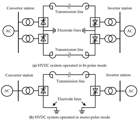
Figure 1.
Operation mode of HVDC system.
1.2. Current Reaserches on Insulation Coordination of Arcing Horns on HVDC Electrode Lines
To solve this problem, the characteristics of fault arcs should be investigated firstly, and an optimized insulation coordination scheme should be studied based the characteristics of fault arcs. Thus, the whole problem involves two aspects: the characteristics of fault arcs and the insulation coordination scheme.
The fault arcs in HVDC systems are long free burning arcs. The long free burning arc (>100 mm) has quite different properties compared with the short arc (<10 mm) and the arc in closed space because of its complex behavior. The existing studies about long arcs are mainly concerned with its movement [1,2,3,4,5] and electrical [4,5,6,7,8,9,10,11] characteristics.
As for the insulation coordination scheme, some studies have been carried out [12,13,14]. Those works can be classified by their methods into two kinds: the maximum arc extinction current method and the U-I characteristic method.
Canellas [12] carried out studies on the extinction of direct current (DC) arcs on long electrode lines based on the experimental results of the Itaipu group, and gave the relations between the maximum arc extinction current and the gap length of arcing horns. However, the maximum arc extinction current is only few hundreds (≤400 A) and the maximum gap length is less than 500 mm, which are not suitable for the HVDC systems with large operation currents used today.
Jankov [13] discussed about the protection performance of arcing horns on the HVDC system with neutral conductor. The static stability criterion Voltage-Current characteristic method (or U-I characteristic method as usually called) was adopted to find the maximum protection region of arc horns. In our previous works. the protection performance of arcing horns in HVDC electrode lines was investigated also based on the U-I characteristic method, and the influence factors were analyzed preliminarily [14]. Although, the U-I characteristic method has been proved to be an effective way for the insulation coordination of arcing horns by [13,14], none of them provided a comprehensive study on the influence factors and the protection performance improvement strategy for arcing horns.
In this paper, the insulation coordination of arcing horns on the electrode lines of a 5000 MW, ±800 kV HVDC system is studied. The U-I characteristic method is used to evaluate the protection performance of arcing horns. Since the protection performance of arcing horns is decided by the characteristics of not only electrode line system but also the fault arc, experiments have been carried out to investigate the characteristics of long free burning arcs. The factors influencing the protection performance of arcing horns are analyzed theoretically. Finally, the improvement strategy for the protection performance of arcing horns is proposed based on the theoretical analysis.
1.3. Static Stability Criterion of Fault Arc on HVDC System (U-I Characteristic Method)
U-I characteristic method [13,14] can be used as the static stability criterion for the fault arc on HVDC system. As shown in Figure 2, the U-I characteristic of fault arc in static state Uarc (I) has a negative power function form [11], on the other hand, the U-I characteristic of external DC system Uex (I) system has a linear function form. Usually, the U-I characteristic of external system is varied with the fault location. Therefore, the possible number of cross point would be zero, one (P) or two (P1, P2) depending on the fault location. The cross points can be regarded as the solutions of state equation Uarc (I) = Uex (I), which actually stands for the possible burning state for the fault arc.
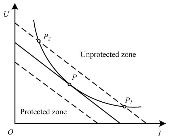
Figure 2.
U-I characteristic method for investigating static stability of fault arc.
If there is no cross point, which means the arc would go into the extinction state. In this situation, the U-I characteristic of the fault arc is higher than the U-I characteristic of the external system, so the external system cannot provide sufficient energy to keep the fault arc burning. The area which is lower than the U-I characteristic of fault arc is called the protected zone.
If there is any cross point, it means the arc would keep burning in some state. In this situation, the U-I characteristic of fault arc is lower than the U-I characteristic of the external system, so the external system can provide sufficient energy to keep the fault arc burning. The area which is higher than the U-I characteristic of fault arc is called the unprotected zone
It should be mentioned that only P1 is a stable burning point (state), while, P2 is an unstable burning point (state) in which any disturbance will lead to a deviation from P2 and a transit to P1 eventually. The critical burning state occurs when P2 and P1 are overlapped at P. In fact, the maximum protection zone is determined by the U-I characteristic curve of the external system where P is located. Hence the maximum protection region is the fault location where the critical burning state happens, and can be used to evaluate the protection performance of arcing horns.
2. Experimental Settings
Figure 3 shows the diagram of our experimental system. A cascade circuit pulse-wave generator (total equivalent capacitance Ceq = 18 mF) is chosen as the power source whose maximum pulse width is 70 ms and peak current is 2500 A. Two steel arcing horns are used as electrodes of which the discharge gap length Lgap is from 400 mm to 1500 mm, and the arcing horns are installed both vertically and horizontally in the experiments. The fault arc is ignited by a ϕ 0.05 mm cooper wire connected to the edge of arcing horns. A 500 MHz oscilloscope (TDS3052C, Tektronix, Beaverton, OR, USA) and a high-speed camera (FASTCAM SA5, Motion Engineering Company, Chicago, IL, USA) are applied to record the voltage, current and development process of fault arc, respectively.
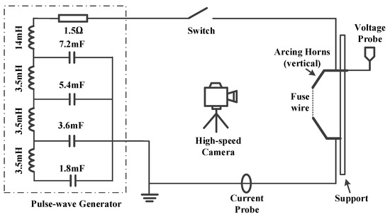
Figure 3.
Diagram of experimental system.
In the experiment, the capacitors are charged firstly to the voltage U0 = 6000 V, and the total energy stored in capacitors is 0.324 MJ. Then, the switch is closed and the energies in capacitors are released to ignite the cooper wire. The arc will be formed and burns in open air freely until the energy runs out.
3. Behaviors and Characteristics of Long Free Burning Arc
3.1. Behaviors of Long Free Burning Arc
3.1.1. Typical Waveforms
The typical current and voltage waveforms of a long free burning arc are shown in Figure 4. The waveform of the arc current pulse is stable, which is caused by the smoothing effect of the circuit inductance on the arc current. However, the waveform of the arc voltage is unstable with many vibrations, which is caused by the instability of the long free burning arc. In the later Section 3.1.3, it is indicated that the instability of long free burning arc is closely related to the local short circuit process of arc column. It should be noticed that the spike (0–0.1 ms) in the wave front of arc voltage is caused by the ignition process of the fuse wire.
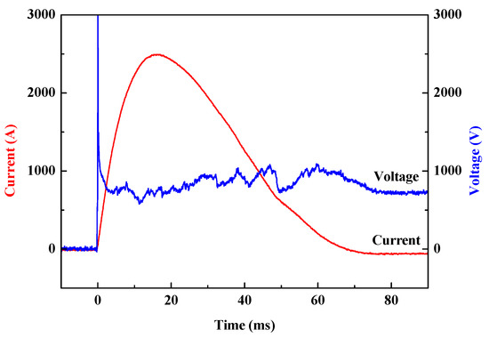
Figure 4.
Typical current and voltage waveforms of a free burning arc.
3.1.2. Development Process of a Long Free Burning Arc
Figure 5 shows the development process of a long free burning arc of which the discharge gap length Lgap = 1000 mm. Figure 6 shows the variation of arc length with time. The whole development process of long free burning arc can be divided into four phases based on the shape of arc column, the motion of arc and the expansion of arc (the variation of arc length):
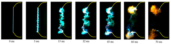
Figure 5.
Development process of long free burning arc (Lgap = 1000 mm).
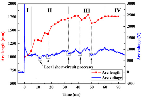
Figure 6.
Variation of arc length and voltage with time (Lgap = 1000 mm).
- Phase I (0.1–3 ms): This phase is called the slow expansion phase. The arc motion is gentle, the arc expansion speed is slow and the arc column is stable with a clear shape.
- Phase II (3–32 ms): This phase is called the fast expansion phase. The arc motion is violent, the arc expansion speed is fast, and the arc column is relative stable. It can be seen that there are blurs around the arc column making the shape of arc column unclear. The blurs are conductive, which will induce the local short circuit processes of arc columns.
- Phase III (32–60 ms): This phase is called the violent motion phase. The arc motion becomes more violent, however, the arc expansion slows down. The blurs around the arc column are diffused which leads frequent local short circuit processes making the arc column unstable and without a clear shape.
- Phase IV (60–70 ms): This phase is called the extinction phase, in which both the arc motion and expansion cease, and the arc is quenched to its final extinction.
It should be mentioned that the initial phase for the case of overvoltage breakdown is different to that of the case of fuse wire ignition. In the case of overvoltage breakdown, the discharge gap is bridged by the streamer before the initial arc formed. Since the streamer usually has a relative curved shape, the shape of initial arc may not be very straight. On the other hand, the huge amount of molecules of the fuse wire guarantee the high conductivity of the arc column, and ambient air is not warm enough to cause strong turbulence at the beginning. As a result, the arc column during phase I for the case of fuse wire ignition is clear and straight. However, the following process should be similar for the two cases.
According to the experimental results, the arc elongates rapidly at first, and then fluctuates around a stable length Lst much longer than the discharge gap length Lgp. Table 1 presents the average stable arc length for the arcing horns at vertical and horizontal configurations, at least 10 experiments have been carried out for each condition.

Table 1.
Average stable arc length of arcing horns at different configurations.
Overall, the average stable arc length increases with the discharge gap length, but the elongation rate αL = Lst/Lgp decreases from 2.4 to 1.6. The difference between the elongation rate of vertical and horizontal gaps is not significant, and the result is similar to [5]. In [5], it is thought that magnetic force is the dominating force at high current level therefore the influence of thermal buoyancy force can be ignored. However, the thermal turbulence can increase the instability of an arc and contribute to the arc motion which usually means a longer arc length, so the explanation of [5] is not very comprehensive. In a later subsection, it is indicated that the insignificant difference of arc length between the vertical and horizontal gaps may be due to local short circuit processes.
3.1.3. Instability of Long Free Burning Arc
The important characteristic of a long free burning arc is the strong instability of arc column. The instability of the arc column is composed of macro instability and micro instability. The arc burning in open air without a confined container remains in motion and violent expansion, so the macro shape of the arc varies with time showing instability. On the other hand, the micro instability is related to the local short circuit process, as shown in Figure 7.
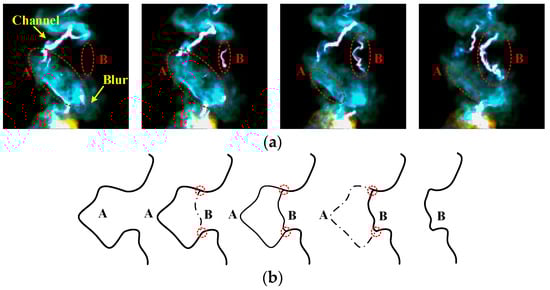
Figure 7.
Local short circuit process of arc column: (a) high speed images of local short circuit process; (b) mechanism diagram of local short circuit process.
For the short arc and arcs in a closed space, there is usually one continuous column channel. However, for the long free burning arc, the arc column is not continuous but rather segmented and composed of short channels and blurs. The blurs can be regarded as the products of cooled channel segments. Hence the conductivity of blurs should be lower than that of the channel. The self-magnetic compression pressure Psm of arc column equals:
where, J is the local current density, and B is the local magnetic field. Since the conductivity of blurs is lower, the local current density of blurs is lower as well. As a result, the self-magnetic compression pressure of blur is weak, and the shape of blurs is divergent. For the long curved channel segment A (as shown in Figure 7b), the voltage drop on channel segment A is large, and the distance between the two terminals is short. Considering that channel segment A is surrounded by the conductive blurs, there is possibility to form a new short pass channel segment B between the two terminals. Once the new short channel segment B is formed, the new short channel segment B will keep growing meanwhile the old long channel segment A will be quenched afterwards forming new blurs. The whole process is called the local short circuit process.
The length as well as the resistance of the new channel segment is smaller than that of the old one. Thus a sudden drop arc voltage will be observed, as shown in Figure 6. Besides, there can be more than one channel segment during the local short circuit process, and the equivalent parallel resistance of channel segments is smaller than single channel segments which will cause a sudden drop of arc voltage as well.
As the blur area is expanded and diffused, the local short circuit process becomes more frequent, enhancing the instability of the arc column. Although the local short circuit process can contribute to the arc motion, it can shorten the arc length. That is the reason why the arc motion is violent but the arc length remains unchanged in Phase III.
A similar explanation can be used for the insignificant difference of arc length between vertical and horizontal gaps. Although the thermal turbulence can make the arc motion more violent which usually means a longer arc length, however, the more frequent local short circuit processes can shorten the arc length. Consequently, the difference of arc length between vertical and horizontal arcing gaps may not be that significant as expected. Besides, the pulse duration in ours experiments is limited, the difference of arc length between vertical and horizontal gaps can be more significant at a longer pulse duration.
3.2. Electric Characteristic of Long Free Burning Arcs
3.2.1. U-I Characteristic of Long Free Burning Arc
The variation of U-I characteristic of long free burning arc with time is shown in Figure 8.
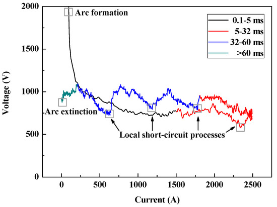
Figure 8.
Variation of U-I characteristic of long free burning arc with time.
The U-I characteristic can also be divided into four phases based on the arc development process:
- Phase I (0.1–3 ms): In this phase, the arc current Iarc rises but the arc voltage Uarc falls off quickly. The U-I characteristic curve Uarc(Iarc) approximately obeys a negative power function law.
- Phase II (3–32 ms): In this phase, the arc current remains at a high level, and on the other hand, the arc voltage shows a slight uptrend with vibrations caused by the local short circuit processes.
- Phase III (32–60 ms): In this phase, the arc current decreases continuously, the arc voltage vibrations are more violent and frequent, which implies frequent local short circuit processes.
- Phase IV (60–70 ms): In this phase, the arc goes into the extinction state, and both the arc current and voltage are decreasing.
3.2.2. E-I Characteristic of Long Free Burning Arc
The majority of arc voltage drops on the arc column for the free burning arc. Therefore, the voltage drop on the arc roots can be neglected. Then the electric field of arc column Earc equals:
where Uarc (V) is the arc voltage and Larc (mm) is arc length at the measured moment respectively. It was found that the relation between the electric field of arc column Earc (V/mm) and the arc current Iarc (A) can be expressed in the following form [11]:
where, a, b and n are both positive constant coefficients. The results of [6] indicated that a = 0.95 V/mm, b = 5 and n = 1 for long air gap. Here, the experimental data are fitted by Equation (3) assuming n = 1, and the fitted results are a = 0.87 V/mm, b = 5.77. Figure 9 presents the variation of arc column electric field with the arc current (E-I characteristic). In [6], the arc elongation was not considered so their calculated electric field Earc = Uarc/Lgp should be higher than the actual electric field Earc = Uarc/Larc.
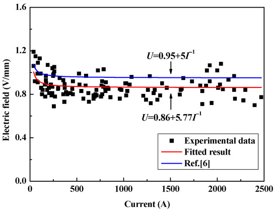
Figure 9.
E-I characteristic of long free burning arc.
4. Insulation Coordination of Arcing Horns on HVDC Electrode Lines
4.1. U-I Characteristic of HVDC Electrode Lines and Fault Arc
4.1.1. U-I Characteristic of HVDC Electrode Lines
The power transfer of a ±800 kV HVDC system is 5000 MW (at bi-polar mode) and its operating current Idc is 3150 A. The lengths of electrode lines on each side is 100 km. The electrode lines are double circuit transmission lines, and the resistance of each electrode line Rl is 4.885 Ω. The resistance of electrode Re is 0.5 Ω, and the tower footing resistance Rt is 15 Ω.
Figure 10 shows the equivalent circuit of a grounding fault on the electrode lines operated in mono-polar mode. Usually the grounding fault on the electrode lines does not influence the operation current and only the static stability of system is of concern, hence the station can be regarded as a DC current source.
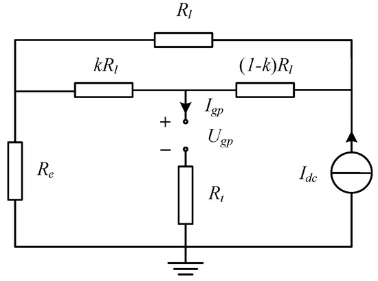
Figure 10.
Equivalent circuit of single line grounding fault on electrode line system.
Here, k represents for the relative fault location:
where Df is the distance from the fault location to the electrode, Ds is the distance from the station to the electrode as well as the length of electrode line. The fault location lie between the electrode and the station, so the value of k should limit in the range from 0 to 1.
According to Kirchhoff’s law, the U-I characteristic of external system Ugp(Igp) is expressed as:
where cn is the conductor number of electrode lines (cn = 2 for this case). Equation (5) is a linear function which can be simplified as:
Here, the coefficients A and B stand for:
4.1.2. U-I Characteristic of Fault Arc
From Equations (2) and (3), the U-I Characteristic of Fault arc Uarc(Iarc) is expressed as:
where a = 0.87 and b = 5.77. Equation (9) is a negative power function which can be simplified as:
Here, the coefficients C and D stand for:
It is supposed that the arc on the arcing horns will elongate from the discharge gap length Lgp to the final stable arc length Lst which is much larger than initial arc length. The stable arc length Lst is taken as the arc length for calculation, the arcing horns with gap lengths of 450, 600, 1000, 1500 mm correspond to the final stable arc lengths Lst of 1100, 1350, 1700, 2500 mm, respectively.
4.2. Protection Region of Arcing Horns
4.2.1. Solutions of State Equation
There is only one solution point for the critical burning state. It is assumed that the current of critical burning state is Icr and the correlated relative fault location is kcr. Combine Equations (6) and (10) and let Ugp = Uarc, Igp = Iarc = Icr, it yields the state equation:
Then rewrite Equation (13) in the form of quadratic equation:
Hence the general solutions of Equation (14) are:
Considering that there is only solution of Icr for the critical burning state, thus:
Noticing that A and B are functions of kcr, the full expression of Equation (16) as a function of kcr is deduced as:
Then rewrite Equation (18) in the form of quadratic equation:
where, A′, B′ and C′ stands for:
Finally, the general solutions of kcr are:
Since there may be two solutions of kcr, there may be two solutions of Icr as well. In the next subsection, it is indicated that not all the solutions of kcr and Icr are reasonable.
4.2.2. Protection Region of Arcing Horns
The protection region of arcing horns is related to kcr only if the real solution of kcr and Icr exists. Figure 11 shows the possible real solutions of kcr and Icr for critical burning states in real plane.
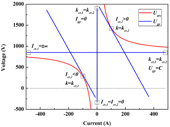
Figure 11.
Possible real solutions of kcr and Icr for critical burning states in real plane.
From Figure 11, it is known that there are two solutions Icr,1 < 0 and Icr,2 > 0 except the situation Icr,1 = Icr,2 = 0 when Igp = 0. In a practical case, Icr should be a limited positive value. Therefore, Icr,2 is a reasonable solution and the special situation Igp = 0 and Ugp = C should also be excluded. The corresponded relative fault location of Icr,2 is kcr,2:
If kcr,2 < 0 which means the arcing horns cannot protect the electrode lines. If kcr,2 > 1 which means the arcing horns protect all the electrode lines. If 0 < kcr,2 < 1 which means the arcing horns protect part of the electrode lines. Finally, the (relative) protection region of arcing horns kp is:
5. Influence Factors on Protection Performance of Arcing Horns
5.1. Analysis Method of Influence Factors Based on Power Balance
5.1.1. Relations between Power Balance, Protection Performance and U-I Characteristics
The essential of static stability of fault arcs is the power balance between the power supplied by external system and the power consumed by the fault arc. If the power supplied by external system is less than the power consumed by the fault arc, then the fault arc will cool down and be extinguished eventually. In other words, if we want a better protection performance for arcing horns, we should reduce the power supplied by the external system and increase the power consumed by the fault arc. This idea is inspired that the analysis of the factors influencing the protection region that can be converted to the analysis of the factors influencing the power balance between the external system and the fault arc.
For a given point on the U-I characteristic, the power P = U·I consumed or released is decided by its position parameters I and U. Therefore the power of a given point can be increased (or reduced) by lifting (or lowering) the U-I characteristic. In the end, the analysis of the influence factors on the protection region can be further converted to the analysis of the influence factors on the U-I characteristic.
5.1.2. Influence of Circuit Parameters on U-I Characteristics
The U-I characteristic of fault arc is in form of Equation (9). According to Equation (9), The U-I characteristic of fault arc can be lifted by increasing the arc length Larc.
On the other hand, the U-I characteristic of external system is in form of Equation (6) which is a linear function. In fact, A is the vertical intercept and B is the slope of Equation (6). The U-I characteristic of external system can be lowered by reducing the vertical intercept or increasing the slope.
5.2. Variation of Protection Performance of Arcing Horns with Circuit Parameters
5.2.1. Arc Length
Although it is the arc length not the discharge gap distance of arcing horns which directly influence the protection region according to the state equations, the discharge gap distance of arcing horns can still have an influence by deciding the stable arc length. Figure 12 shows the influence of arc length on the protection region of arcing horns. The protection region increases almost linear with the arc length. Longer arc length means larger energy consumption of arc, so that the U-I characteristic of fault arc will be lifted, and the protection region of arcing horns increases with the arc length. The arcing horns can protect the electrode line only if the stable arc length is more than 1100 mm. For the arcing horns with 1500 mm discharge gap length whose stable arc length is 2500 mm, the protection region is just 20.1%. It can be concluded that the arcing horns has poor protection performance for electrode lines of larger operation current and long distance.
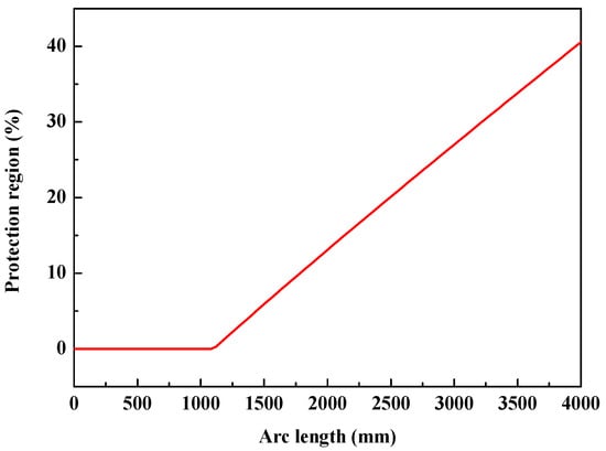
Figure 12.
Influence of arc length on protection region of arcing horn.
5.2.2. Tower Footing Resistance
Figure 13 and Table 2 show the influence of tower footing resistance on the protection region of arcing horns. The protection region increases with the tower footing resistance, but the influence decreases as the tower footing resistance increases.
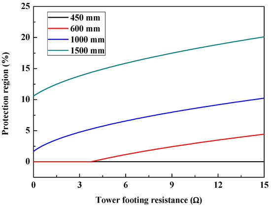
Figure 13.
Influence of tower footing resistance on protection region of arcing horns.
Table 2.
Influence of tower footing resistance on protection region of arcing horns.
Since the slope B increases with the tower footing resistance, the U-I characteristic of external system will be lowered which means the energy supplied by the external system will decrease as well. Finally, the protection region of arcing horns increases with the tower footing resistance.
5.2.3. Electrode Resistance
Figure 14 and Table 3 show the influence of electrode resistance on the protection region of arcing horns. As the result shown, the protection region decreases almost linearly with the electrode resistance, and the arcing horns is invalid for protection at large electrode resistance.
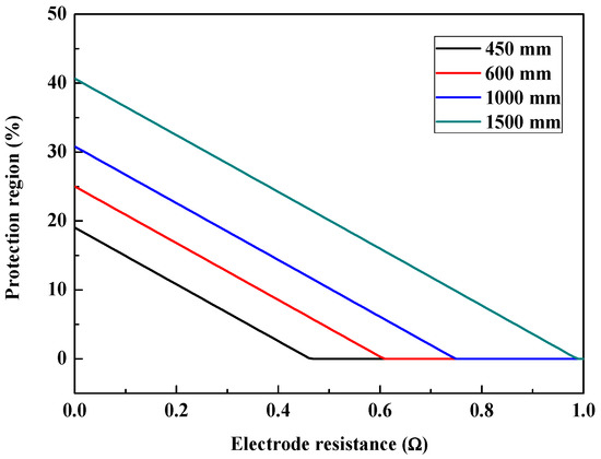
Figure 14.
Influence of electrode resistance on protection region of arcing horns.
Table 3.
Influence of electrode resistance on protection region of arcing horns.
Both the vertical intercept A and the slope B increase with the electrode resistance Re. However the effect of Re on B is limited because Rt and Rl are usually much larger than Re, hence the effect of Re on A is dominant. As a consequence, the U-I characteristic of external system will be raised which means the energy supplied by the external system will increase, and the protection region of arcing horns decreases with the electrode resistance.
5.2.4. Line Resistance
Figure 15 and Table 4 show the influence of line resistance on the protection region of arcing horns. The protection region decreases with the line resistance, but the rate of decline falls off with the line resistance. A full protection can be realized at small line resistance which demonstrates that arcing horns are very effective for short HVDC electrode lines. For the line resistance Rl, both the vertical intercept A and the slope B increase with Rl. When Rl is small, the effect of Rl on A is dominated, and the U-I characteristic of external system will be lifted which means the energy supplied by the external system will increase. Thus the protection region decreases with the line resistance. As Rl increases, the effect of Rl on B becomes stronger, so that the rate of decline of the protection region falls off.
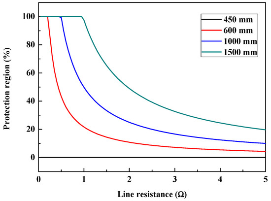
Figure 15.
Influence of line resistance on protection region of arcing horns.
Table 4.
Influence of line resistance on protection region of arcing horns.
5.2.5. Operation Current
Figure 16 and Table 5 show the influence of operation current on the protection region of arcing horns. The protection region decreases with the operation current, but the rate of decline falls off with the operation current. A full protection can be realized at low operation current which demonstrates that arcing horns are very effective for HVDC electrode lines with small operation currents. For the operation current Idc, the vertical intercept A increases with Idc, and the U-I characteristic of external system will be lifted which means the energy supplied by the external system will increase. Therefore the protection region of arcing horns decreases with the operation current.
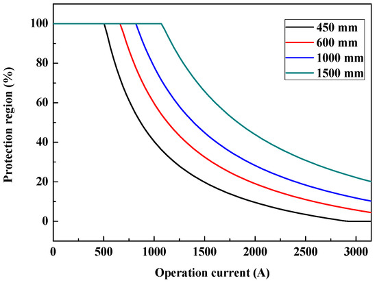
Figure 16.
Influence of operation current on protection region of arcing horns.
Table 5.
Influence of operation current on protection region of arcing horns.
5.2.6. Conductor Number
Figure 17 and Table 6 show the influence of conductor number on the protection region of arcing horns. The protection region increases almost linearly with the conductor number. For the conductor number cn, both vertical intercept A and the slope B decrease with cn. As Rt counts majority part of B, the effect of cn on B is limited, in turn, the effect of cn on A is dominant, so the U-I characteristic of the external system will be lowered which means the energy supplied by the external system will decrease, and the arcing horns protection region will increase.
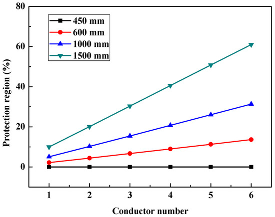
Figure 17.
Influence of conductor on protection region of arcing horns.
Table 6.
Influence of conductor on protection region of arcing horns.
5.3. Analysis on Influence Factors Based on Approximation Solution of State Equation
5.3.1. Approximation Solution of State Equation
The full expression of Equation (25) is quite complex for analysis. In this subsection, the approximation solution of state equation will be proposed for further analysis on influence factors.
Generally, the total resistance of whole electrode lines should be as small as possible to ensure they are well grounded, otherwise a relatively high voltage will drop on the electrode lines which is not expected. In addition, large tower footing resistance can improve the performance of arcing horns. Therefore, it is proper to suppose that Rt >> Rl and Re, and Equation (18) can be simplified into:
and then the approximation solutions of kcr are:
Finally, the approximation protection region of arcing horns k′p is:
5.3.2. Analysis on Influence of Circuit Parameters Based on Approximation Solutions
The derivatives of approximation protection region k′p with respect to Larc, Re, Rl, Rt, Idc and cn are:
when 0 ≤ k′p ≤ 1. It is obvious that: dk′p/dRe and dk′p/dcn are constants; dk′p/dLarc and dk′p/dRt are positive; dk′p/dRe and dk′p/dIdc are negative. The signs of dk′p/dRl and dk′p/dcn are decided by the specific circuit parameters. Under our conditions that Idc = 3150 A, Re = 0.5 Ω, Rt = 15 Ω, a = 0.87 V/mm, b = 5.77 and Larc = 1100~2500 mm, dk′p/dRl < 0 and dk′p/dcn > 0.
For the arc length Larc, when Larc is very large, dk′p/dLarc ≈ αcn/RlIdc > 0 can be assumed a constant. Therefore, the protection region increases linearly with the arc length.
For the electrode resistance Re and the conductor number cn, considering that dk′p/dRe is a negative constant while dk′p/dcn is a positive constant, which implies that the protection region will decrease with the electrode resistance but increase linearly with the conductor number.
For the line resistance Rl and the operation current Idc, both of dk′p/dRl and dk′p/dIdc are negative with a saturation trend according to Equations (32) and (34). Therefore, the protection region will decrease with the line resistance and the operation current, but the rate of decline falls off gradually.
For the tower footing resistance Rt, dk′p/dRt are positive and decreases with Rt according to Equation (33). Consequently, the protection region will increase with the tower footing resistance, but the influence decreases as the tower footing resistance increases.
The above theoretical analysis based on the approximation solutions coincides well with the results calculated by the state equations shown in Section 5.2. It is proved that the approximation solutions (Equations (30)–(35)) can be a useful tool for the fast evaluation of influence factors on the protection performance of arcing horns.
6. Protection Performance Improvement Methods for Arcing Horns
6.1. Protection Performance Improvement by Adjusting Circuit Parameters
The efficient ways to improve the protection performance of arcing horns is increasing the arc voltage and tower footing resistance, and reducing the total resistance of electrode line system (including the line resistance and electrode resistance).
According to Equation (10), the arc voltage Uarc can be elevated by elongating the arc length Larc or cooling the arc to increase the arc constants a and b. Increasing the discharge gap length of arcing horns is the simplest way to elongate the arc length. Auxiliary devices for arc extinction are also recommended to improve the protection performance. In [15,16,17], a gas jet was used to elongate the arc and promote the arc cooling process.
Increasing the diameter of the conductor and conductor number can reduce the line resistance, however, extra expense is required. In [14], neutral conductor was used as additional ground return which can reduce the total resistance of electrode line system, so that a better protection performance is achieved.
6.2. Protection Performance Improvement by Diffirential Arcing Horns Configuration Strategy
Figure 18 shows the variation of U-I characteristic of external system with the fault location. The U-I characteristic of the place near the station is higher than that of the place near the electrode. That is to say, arc extinction is harder for a place near the station.
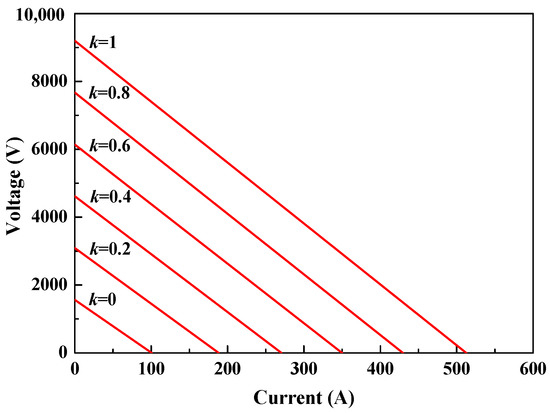
Figure 18.
U-I characteristic of external system at different fault location.
In the place near the electrode, the arcing horns with short discharge gap length is enough for full protection. Wherever, in the place near the station, even the arcing horns with long discharge gap length may not achieve full protection, and auxiliary devices for arc extinction are needed as well. Considering that the arc extinction devices will incur extra expenses, it is unnecessary to install the arc extinction devices all along the electrode lines. Therefore, the diversified configuration strategy of arcing horns is recommended for cost savings, which means arcing horns of short discharge gap length are sufficient and recommended for the place near the electrode, meanwhile, arcing horns of long discharge gap length with additional arc extinction devices are recommended for the places near the station.
7. Conclusions
In this paper, experiments were carried out to study the characteristics of long free burning arcs and the insulation coordination of arcing horns on the electrode lines of a 5000 MW, ±800 kV HVDC system. The factors influencing the protection performance of arcing horns are analyzed theoretically. The main conclusions are summarized as follows:
- (1)
- The development process of long free burning arcs can be divided into slow expansion, fast expansion, violent motion and extinction phases. The long free burning arc column is very unstable and made up of segments of short channels and conductive blurs. The local short circuit is thought to be the main cause of the instability of arc column.
- (2)
- The arcing horns are only suitable for the HVDC electrode lines systems of low operation current and short distance. For the HVDC electrode lines systems of high operation current and long distance, the protection performance of arcing horns is limited, and additional auxiliary devices for arc extinction are needed to realize full protection.
- (3)
- The effect ways for the protection performance improvement of arcing horns are increasing the arc voltage and tower footing resistance, and reducing the total resistance of HDVC electrode line system. Differential arcing horns configuration strategy is recommended for cost saving.
Acknowledgments
This work was supported by Central Southern China Electric Power Design Institute (CSEPDI) of China Power Engineering Consulting Group Corporation (DG1-A04-2013).
Author Contributions
Xiandong Li analyzed the data, performed the experiment, and wrote the paper; Hua Li conceived and designed the experiments; Yi Liu and Fuchang Lin gave suggestions on the experiments.
Conflicts of Interest
The authors declare no conflict of interest.
References
- Gu, S.Q.; He, J.L.; Zeng, R.; Zhang, B.; Xu, G.Z.; Chen, W.J. Motion characteristics of long ac arcs in atmospheric air. Appl. Phys. Lett. 2007, 90, 051501. [Google Scholar] [CrossRef]
- Li, Q.M.; Cong, H.X.; Sun, Q.Q.; Xing, J.Y.; Chen, Q. Characteristics of Secondary AC Arc Column Motion Near Power Transmission Line Insulator String. IEEE Trans. Power Deliv. 2014, 29, 2324–2331. [Google Scholar] [CrossRef]
- Sima, W.X.; Tan, W.; Yang, Q.; Luo, B.; Luo, L. Experimental research on power frequency arc movement process of 110 kV composite insulators in rod shape parallel gap lightning protection devices. Proc. CSEE 2011, 32, 114–121. [Google Scholar]
- Kinya, S.; Inaba, T. Electric and moving characteristics of dc kilo-ampere high current arcs in atmospheric air. Electr. Eng. Jpn. 1990, 110, 9–20. [Google Scholar]
- Stokes, A.D.; Oppenlander, W.T. Electric arcs in open air. J. Phys. D Appl. Phys. 1991, 24, 26–35. [Google Scholar] [CrossRef]
- Goda, Y.; Iwata, M.; Ikeda, K.; Tanaka, S. Arc voltage characteristics of high current fault arcs in long gaps. IEEE Trans. Power Deliv. 2000, 15, 791–795. [Google Scholar] [CrossRef]
- Terzija, V.; Preston, G.; Popov, M.; Terzija, N. New static “airarc” EMTP model of long arc in free air. IEEE Trans. Power Deliv. 2011, 26, 1344–1353. [Google Scholar] [CrossRef]
- Strachan, D.C. High-current, steel-cathode, free-burning arcs. J. Phys. D Appl. Phys. 1977, 10, 361–370. [Google Scholar] [CrossRef]
- Sölver, C.E. Electric Arcs and Arc Interruption. Chalmers University of Technology, Götenburg, Sweden, EEK 195 High Voltage Technology, Lecture. Available online: http://193.140.122.139/high_voltage/elkraft/www.elkraft.chalmers.se/GU/EEK195/lectures/Lecture7.pdf (accessed on 17 January 2018).
- Paukert, J. The arc voltage and the resistance of LV fault arcs. In Proceedings of the 7th International Symposium on Switching Arc Phenomena, Łódź, Poland, 27 September–11 October 1993; pp. 49–51. [Google Scholar]
- Ammerman, R.F.; Gammon, T.; Sen, P.K.; Nelson, J.P. DC-arc models and incident-energy calculations. IEEE Trans. Ind. Appl. 2010, 46, 1810–1819. [Google Scholar] [CrossRef]
- Canellas, J.; Clarke, C.D.; Portela, C.M. DC Arc Extinction on Long Electrode Lines for HVDC Transmission. In Proceedings of the International Conference on DC Power Transmission (ICDCPT), Montreal, QC, Canada, 4–8 June 1984; pp. 127–133. [Google Scholar]
- Jankov, V.; Stobart, M. HVDC system performance with a neutral conductor. In Proceedings of the 2010 International Conference on High Voltage Engineering and Application (ICHVE), New Orleans, LA, USA, 11–14 October 2010; pp. 188–191. [Google Scholar]
- Li, X.D.; Li, H.; Liu, Y.; Lin, F.C.; Xu, Z.J. Experimental study on insulation coordination of arcing horns on HVDC electrode lines. In Proceedings of the 19th International Symposium on High Voltage Engineering, Pilsen, Czech, 23–28 August 2015. [Google Scholar]
- Ohtaka, T.; Iwata, M.; Tanaka, S.; Goda, Y. Development of an EMTP simulation model of arcing horns interrupting fault current. IEEE Trans. Power Deliv. 2010, 25, 2017–2024. [Google Scholar] [CrossRef]
- Wang, J.F.; Liu, J.L.; Wu, G.Q.; Liu, Q.; Guo, W. Research and application of jet stream arc-quenching lightning protection gap (JSALPG) for transmission lines. IEEE Trans. Dielectr. Electr. Insul. 2015, 22, 782–788. [Google Scholar] [CrossRef]
- Wang, J.F.; Wu, D. Development of an arc-extinguishing lightning protection gap for 35 kV overhead power lines. IET Gener. Transm. Distrib. 2017, 11, 2897–2901. [Google Scholar] [CrossRef]
© 2018 by the authors. Licensee MDPI, Basel, Switzerland. This article is an open access article distributed under the terms and conditions of the Creative Commons Attribution (CC BY) license (http://creativecommons.org/licenses/by/4.0/).