Article

Efficient Polymer Solar Cells with Alcohol-Soluble Zirconium(IV) Isopropoxide Cathode Buffer Layer

1
State Key Laboratory of Alternate Electrical Power System with Renewable Energy Sources, North China Electric Power University, Beijing 102206, China
2
Department of Mathematics, Quiad-I-Azam University, Islamabad 44000, Pakistan
3
NAAM Research Group, Faculty of Science, King Abdulaziz University, Jeddah 21589, Saudi Arabia
*
Author to whom correspondence should be addressed.
Energies 2018, 11(2), 328; https://doi.org/10.3390/en11020328
Submission received: 6 January 2018 / Revised: 22 January 2018 / Accepted: 29 January 2018 / Published: 2 February 2018
(This article belongs to the Section I: Energy Fundamentals and Conversion)

Abstract

:
Interfacial materials are essential to the performance and stability of polymer solar cells (PSCs). Herein, solution-processed zirconium(IV) isopropoxide (Zr[OCH(CH3)2]4, ZrIPO) has been employed as an efficient cathode buffer layer between the Al cathode and photoactive layer. The ZrIPO buffer layer is prepared simply via spin-coating its isopropanol solution on the photoactive layer at room temperature without any post-treatment. When using ZrIPO/Al instead of the traditionally used Ca/Al cathode in PSCs, the short-circuit current density (Jsc) is significantly improved and the series resistance of the device is decreased. The power conversion efficiency (PCE) of the P3HT:PCBM-based device with ZrIPO buffer layer reaches 4.47% under the illumination of AM1.5G, 100 mW/cm2. A better performance with PCE of 8.07% is achieved when a low bandgap polymer PBDTBDD is selected as donor material. The results indicate that ZrIPO is a promising electron collection material as a substitute of the traditional low-work-function cathode for high performance PSCs.

1. Introduction

Polymer solar cells (PSCs) have been gaining increasing attention due to their promising prospects for low-cost, portable and flexible modules [1,2,3], and the solution processability makes them very easy to be fabricated via roll-to-roll techniques [4]. After years of efforts, the certified power conversion efficiency (PCE) of single-junction PSCs has climbed above 11% since the bulk heterojunction (BHJ) architecture has been adopted to form a sandwich device [5,6], in which a nanoscale photoactive layer is sandwiched between the high work function anode and the low work-function (WF) cathode [7,8]. Unfortunately, large scale practical application has been inhibited by the poor stability of the devices because the commonly adopted cathode buffer layer (CBL, e.g., calcium (Ca) or barium (Ba)) is prone to oxidative degradation as well as the instable photoactive layer and anode modification layer [9,10,11]. In addition, it is difficult to avoid the interdiffusion of active metal atoms of CBL at the photoactive-layer/metal interface during the thermal evaporation of the CBL, and thus, this leads to an evident performance decrease for PSCs [12] Undoubtedly, the alternative CBL candidates of alkali metal compounds (such as LiF, CsF and Cs2CO3) suffer from both of the vacuum involved deposition techniques, which are incompatible with all solution processed PSCs [13,14]. Therefore, considerable efforts have been directed to exploring a stable and solution-processable CBL between an active layer and a cathode since interfacial engineering is a critical factor for the stability improvement of PSCs [15].
For ideal solution-processable CBL, the energetic level offsets between the donor and electrodes could be reduced to form an ohmic with less series resistance besides its good hole-blocking ability, thereby improving charge transport and extraction [16]. Meanwhile, the capability of restraining the mutual diffusion of reactive metal atoms and protecting the photoactive layer should be good enough, which are also benefical for PCE enhancement [17]. Fullerene derivatives have been demonstrated to be promising CBL substitutes due to their strong electron-accepting ability, suitable work function and similar structures with fullerene acceptors [18,19,20]. Recently, the energy level alignment between the photoactive layer and the cathode interface was adjusted efficiently after introducing C60 bisadduct surfactant in BHJ-PSCs, and consequently realizing an increase in opencircuit voltage (Voc) [21]. Page et al. successfully reduced the WF of Ag, Cu, and Au electrodes to 3.65 eV and obtained a high PCE of exceeding 8.5% by incorporating CBL of fulleropyrrolidines with amine (C60-N) or zwitterionic (C60-SB) in PSCs [22]. Very recently, an alcohol-soluble fullerene aminoethanol derivative (C60-ETA) was used as CBL in traditional BHJ-PSCs, and a PCE of 9.66% was achieved [15]. However, there are three aspects for an ideal CBL that have to be addressed in addition to the capability of fine-tuning energy level as mentioned above. The first relates to adequate alcohol/water solubility in the case of intermixing at the active layer and the interlayer. The second involves its simple fabrication process with low temperature technology, and the last deals with its good photoelectrical properties [12,17]. Apparently, such fullerene derivative CBLs are subjected to the complex multi-step synthesis for increasing their alcohol solubility.
Some solution-processed transition metal chelates (such as titanium chelates and zirconium chelates) are a very attractive CBL substitute stemming from their high electron mobility, energetic level alignment to form ohmic contact, solution processability with protonic solvents and high optical transparency [23,24,25]. Furthermore, these kinds of materials can be applied as CBL without decomposition into metal oxides and elimination of high temperature annealing process in conventional BJH-PSCs solar cells [12]. Hence, these kind of materials are more promising than the metal oxide CBL materials (TiOx [26,27], ZnO [28,29] and CeOx [30,31] et al.). Our previous studies found that the introduction of water-soluble nickel acetate (Ni(CH3COO)2, NiAc) CBL can decrease the series resistance and a 9.23% PCE was achieved for the PSC based on D–A copolymer PBDTBDD as electron donor [32]. However, studies on these kinds of desirable materials are rare and the mechanisms need to be further understood. Consequently, development of water/alcohol soluble transition metal chelates with good energy level alignment, facile synthesis and good photoelectricity are in urgent demand [12].
The objective of the present study is to utilize a novel CBL material of ZrIPO via simple spin-coating technique at room temperature, and further evaluate its feasibility in PSCs when used instead of the traditional Ca CBL. We found that the solution-processed ZrIPo layer is highly transparent in the visible range, and its effectiveness of electronic collection is verified both in P3HT:PCBM-based devices and PBDTBDD:PCBM-based cells. Compared with the cases of Ca CBL, the PCE of the P3HT:PCBM-based device with ZrIPO buffer layer reaches 4.47%, and a more remarkable performance with PCE up to 8.07% is exhibited for PBDTBDD:PCBM-based cell under the illumination of AM1.5G, 100 mW/cm2. Our results elucidate that ZrIPO is a potential ideal cathode modification layer in PSCs.

2. Experimental Details

2.1. Materials and Instrumentation

Patterned indium tin oxide (ITO) coated glass substrates with a sheet resistance of 10 Ω/□ were purchased from CSG HOLDING Co., LTD (Shenzhen, China). Poly(3,4-ethylenedioxythiophene): poly(styrenesulfonate) (PEDOT:PSS) (Clevious P VP AI 4083) was purchased from H.C. Stark company (Newton, MA, USA). P3HT was purchased from Rieke Metals. PC60BM (Purity > 99.0%) was purchased from Nano-C (Westwood, MA, USA). ZrIPO was purchased from Alfa Aesea (Haverhill, MA, USA). 1,8-Diiodooctane (DIO, Purity > 98.0%) was purchased from Sigma Aldrich (St. Louis, MO, USA). PBDTBDD was synthesized according to previous report [14]. All the commercially available materials were used as received without further purification.
Tapping mode atomic force microscope (AFM) was performed on a VEECO DICP-II instrument (Agilent Technologies China, Beijing, China). Ultraviolet photoemission spectroscopy (UPS) was conducted using a Thermo Scientific ESCA Lab 250Xi electron spectrometer (Waltham, MA, USA). The gas discharge lamp was used for UPS, with helium gas admitted and the He I (21.22 eV) emission line employed. The helium pressure in the analysis chamber during analysis was about 2 × 10⁻⁸ mbar. The data were acquired with −10 V bias and the energy resolution was 0.02 eV.

2.2. Device Fabrication and Characterization
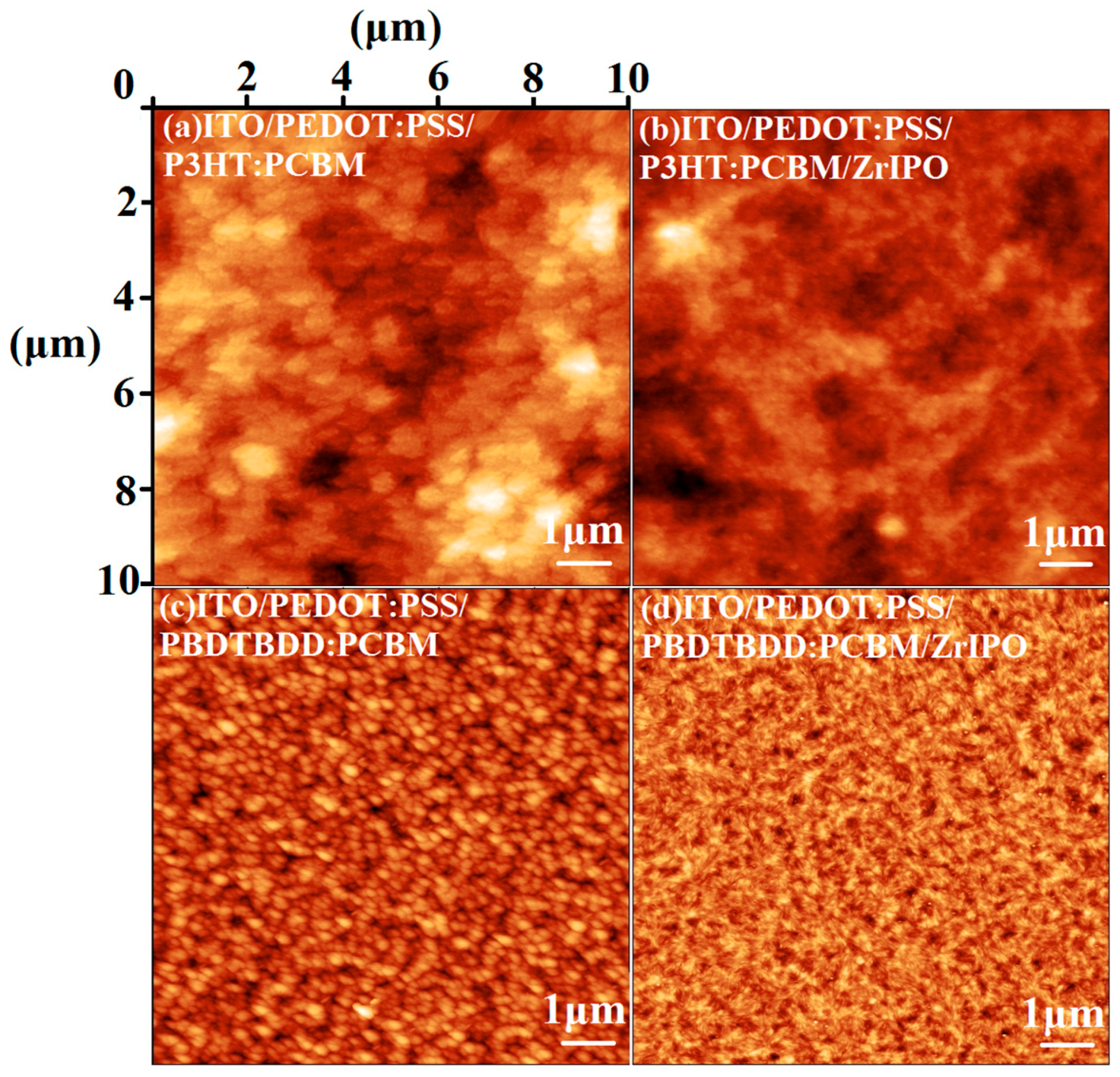
To verify the feasibility of ZrIPO as electron collection material for BHJ-PSCs, we compared the performance of the devices with bare Al, Ca/Al or ZrIPO/Al as cathode. Six types of architectures were designed by using P3HT:PCBM or PBDTBDD:PCBM as photoactive layer:
(A)
ITO/PEDOT:PSS/P3HT:PCBM/Al,
(B)
ITO/PEDOT:PSS/P3HT:PCBM/Ca/Al,
(C)
ITO/PEDOT:PSS/P3HT:PCBM/ZrIPO/Al,
(D)
ITO/PEDOT:PSS/PBDTBDD:PCBM/Al,
(E)
ITO/PEDOT:PSS/PBDTBDD:PCBM/Ca/Al,
(F)
ITO/PEDOT:PSS/PBDTBDD:PCBM/ZrIPO/Al.
The ITO substrates were sequentially cleaned by detergent, de-ionized water, acetone, and isopropanol in ultrasonic cleaner. The ITO substrate was then transferred into a ultraviolet (UV) ozone chamber for treatment. The PEDOT:PSS anode buffer layer was fabricated by spin coating a PEDOT:PSS aqueous solution on the pre-treated ITO substrate and followed by annealing at 150 °C for 10 min. Polymer P3HT and PBDTBDD were used as donor materials and fullerene derivative PCBM was used as acceptor material. Deposition of the photoactive layer was under our optimized fabrication conditions [33,34,35]. The P3HT and PCBM (1:1 w/w) were dissolved in a 1,2-dichlorobenzene solution with a polymer concentration of 20 mg/mL. The solution was spin-coated onto the PEDOT:PSS-modified substrate and then solvent annealed for 2 h. The thickness of the photoactive layer was controlled to be ~230 nm [36]. The PBDTBDD:PCBM blend layer was prepared by spin coating a mixed 1,2-dichlorobenzene solution of PBDTBDD:PCBM (1:1 w/w, polymer concentration of 15 mg/mL) with 3% volume ratio of DIO additive onto the PEDOT:PSS-modified substrate. The thickness of the PBDTBDD:PCBM layer was controlled to be ~100 nm. The optimized ZrIPO buffer layer was prepared by spin-coating a 1.5 mg/mL ZrIPO-ethanol solution at 3000 rpm for 40 s on the photoactive layer, and no post-treatment was performed. The thickness of ZrIPO film is about 12 nm. Finally, a 10 nm Ca and 100 nm Al were evaporated onto the photoactive layer in vacuum.
A Keithley 2400 Source Measure Unit (Tektronix China, Shanghai, China) was used to measure the current density-voltage (J–V) characteristics of the devices. A simulated AM1.5G solar irradiation with light intensity of 100 mW cm−2 (from SAN-EI LTD., Tokyo, Japan, AAA grade) was used as the light source. The measurement was performed in a nitrogen filled glove box. The measurement of the incident photon to electron conversion efficiency (IPCE) was conducted under the control of QE-R system (Enli Tech., Kaohsiung, Taiwan) in air. The intensity of each wavelength was calibrated by the standard single-crystal silicon photovoltaic device.

3. Results and Discussion

The ZrIPO buffer layer was prepared via a simple spin-coating method without any post-treatment, which can suppress the interdiffusion of the reactive metal atoms. Ultraviolet photoelectron spectroscopy (UPS) measurement was used to investigate the energy levels of the ZrIPO film. The left panel in Figure 1a shows the secondary edge at high binding energy region, related to work function and the right panel in Figure 1a shows the photoemission onset and valence band edge with respect to the Fermi level. The WF of the ZrIPO is ~3.45 eV obtained from the photoemission onset of the spectra. The valence band edge (VB) of ZrIPO is determined to be ~7.65 eV. Apparently, it is easy to form a high hole barrier between the interface of PCBM/ZrIPO and effectively block the holes from transporting to the cathode. The bandgap (Eg) of the ZrIPO film is determined to be ~5.72 eV, which is calculated from the absorption spectra of ZrIPO using Tauc’s law (as shown in Figure 1b) [37]. The conduction band (CB) is estimated to be ~1.93 eV by the subtraction of Eg from the VB. This energy levels affords ZrIPO excellent electron collection efficiency and hole blocking ability.
The molecular structures of P3HT, PBDTBDD and PCBM are shown in Figure 2a and the device structure of PSCs using ZrIPO as cathode buffer layer is shown in Figure 2b, where the ITO and Al work as the anode and cathode electrode, respectively. Figure 2c demonstrates the HOMO and LUMO energy levels of the materials involved in the PSCs. According to the analysis of UPS and absorption spectra, ZrIPO shows a large band gap of 5.72 eV with WF of 3.45 eV and VB of 7.65 eV. The WF of ZrIPO buffer layer locates much lower than the LUMO level of PCBM. According to the universal energy level alignment rules, the Fermi level of the ZrIPO will be pinned to the LUMO level of the organics [38,39,40,41,42], where spontaneous electron extraction from PCBM to ZrIPO can be expected. The behavior of energy-level alignment at the organic semiconductor/electrode heterointerface leads to the formation of ohmic contact at the cathode side, which is critical for the Voc of PSCs. For the PSCs where ohmic contacts are formed with both electrodes, the Voc is determined by the difference between the HOMO of the donor and the LUMO of the acceptor [43]. On the other hand, the deep VB of ZrIPO leads to formation of a high barrier which blocks the holes from transporting to the cathode efficiently. All of these features make ZrIPO an outstanding electron selective material for PSCs.
It is well known that only the light absorbed by the photoactive layer is valuable for generating excitons and contributing to the enhancement of PCE [12]. Hence, high optical transparency of CBL is a crucial parameter for guarantying the adequate absorption of the photoactive layer. Figure 3 presents the absorportion spectra of ZrIPO on the quartz substrate. The absorption from 250 to 900 nm is lower than 2%, exhibiting ultrahigh transparency in the visible and near infrared regions. Obviously, ultrahigh transparency indicates that ZrIPO is a prominent CBL material.
AFM technique with tapping-mode was performed to demonstrate the nanoscale morphologies of P3HT:PCBM and PBDTBDD:PCBM photoactive layer without and with ZrIPO cathode modification layer on ITO/PEDOT:PSS substrates, as shown in Figure 4. The surface root mean square (RMS) roughness of the P3HT:PCBM photoactive layer without ZrIPO layer in Figure 4a was 15.7 nm. In contrast, the rougher surface with the RMS of 18.3 nm in Figure 4b shows increased contact area, leading to stronger interfacial adhesion between the photosensitive layer and the Al electrode. Similar results can be found in Figure 4c,d. The RMS of PBDTBDD:PCBM photoactive layer is increased from 4.62 nm to 4.92 nm after modification by ZrIPO layer, and the Figure 4c suggests weaker interfacial contact. The results elucidate that the interfacial contact with increased contact area and interfacial adhesion can be obtained after introducing ZrIPO buffer layer, which foretells a remarkable reduction in series resistance and therefore contribute to the electron collection ratio [12,15,21].
Six types of PSCs devices labeled as A–F were fabricated based on P3HT:PCBM (A, B, C) and PBDTBDD:PCBM (D, E, F) to further compare and verify the effectiveness of ZrIPO CBL. Devices A and D are control samples with bare Al electrodes. Devices B and E are control samples with conventional Ca/Al electrodes, and device C and F are the control samples with ZrIPO CBL. The current density-voltage (JV) characteristics of the devices, both in the dark and under the illumination of AM1.5G, 100 mW/cm2, are dependent on the cathode employed, as shown in Figure 5a,b. The device parameters (averaged over 12 individual devices) are summarized in Table 1. The series resistance (Rs) of the devices is approximately obtained from the inverse of the slope of the JV curves under dark condition at 1 V. The IPCE spectra of the PSCs are given in Figure 5c,d.
As can be seen from Figure 5a,b and Table 1, the control devices A and D with Al as cathode show the poorest performance. The Voc and short-circuit current density (Jsc) of device A are only 0.52 V and 8.96 mA/cm2, much lower than the commonly reported values for P3HT:PCBM based devices [44,45,46]. The WF of Al cathode is located between the electron affinity (EA) and ionization potential (IP) of PCBM, therefore, Schottky contact will be formed at the organic/Al interface, which results in an energy loss and thus a reduced Voc. According to the series resistances obtained from the dark JV characteristics of the devices, bare Al cathode leads to highest series resistance of the device, which is unfavorable for photocurrent enhancement. The low Voc and Jsc, coupled with the low FF, leads to a poor device performance. By inserting a low WF Ca at the organic/Al interface, the WF of the cathode can be decreased to 2.9 eV, which is located above the HOMO of the PCBM. The Fermi level will be pinned to the HOMO level of the PCBM, leading to an ohmic contact with a Rs of 3.5 Ω cm2, which is much lower than the value of 7.6 Ω cm2 for the device A. The ohmic contact is beneficial to decreasing the energy barrier in electron collection and series resistance of the device, thus yielding enhancement in both Voc and Jsc. The Voc, Jsc and fill factor (FF) of device B can be enhanced to 0.60 V, 9.85 mA/cm2 and 62.4%, respectively, leading to a higher of PCE of 3.69%. The device can be further improved by using ZrIPO/Al instead of Ca/Al as cathode. The Jsc and FF can reach as high as 11.0 mA/cm2 and 67.7%, respectively, and the Rs further reduce to 1.2 Ω cm2 while maintaining the Voc at 0.60 V, thus obtaining a higher PCE of 4.47%. This can also be verified by the dark JV characteristics in inset of Figure 5a. In brief, the Rs are 7.6, 3.5 and 1.2 Ω cm2 for PSCs with bare Al, Ca/Al and ZrIPO/Al cathode, respectively, which precisely clarify the charge transporting improvement, thereby resulting in the increase of Jsc and Voc. Correspondingly, the IPCE spectra of the PSCs presents enhanced photocurrent response showed in Figure 5c. The integrated Jsc from IPCE spectra are 8.59, 9.71 and 10.5 mA/cm2, respectively, very close to that (8.96, 9.85 and 11.0 mA/cm2) derived from JV curves.
The same trend for the performance improvement can be found for the devices based on PBDTBDD:PCBM blend with bare Al, Ca/Al and ZrIPO/Al cathode. The device E affords a PCE of 5.48%, with a Voc of 0.79 V, a Jsc of 10.7 mA/cm2, a FF of 64.8% and a Rs of 12.5 Ω cm2. The four parameters of PCE Voc, Jsc and FF are all significantly boosted to 7.16%, 0.87 V, 11.55 mA/cm2 and 71.2%, respectively for the device E with Ca/Al cathode, while the Rs is markedly reduced to 4.6 Ω cm2 in comparison with device of D. As expected, the device F with the ZrIPO CBL demonstrate superior performance than all other devices with bare Al and Ca/Al cathode. The Rs is dramatically reduced to 1.2 Ω cm2 ascribe to its better capability of energy level adjustment. The Voc is slightly increased to 0.89 V and Jsc is distinctly enhanced to 12.95 mA/cm2, which reflect the good charge transport and extraction ability of ZrIPO. Consequently, the PCE of device F surpasses samples with Ca in traditional structure, and achieves an increased maximum PCE of 8.07%. Moreover, the tiny standard deviations of PCEs in Table 1 indicate that the changed buffer layers affect slightly the spread in device performance and are reliable with reproducibility. Figure 5d illustrates the IPCE spectra of the PSCs, which gives a fairly clear image for enhanced photocurrent response. The integrated Jsc from IPCE spectra are very closed to the data (10.70, 11.56 and 12.95 mA/cm2) from J–V curves, they are (10.36, 11.15 and 12.48 mA/cm2), respectively.
Summarizing from Figure 5 and Table 1, we can find that the ZrIPO modified PSCs illustrated obviously enhanced PCE with significantly increased Jsc, relatively improved Voc and greatly decreased Rs. The performance improvement can be attributed to the enhanced ohmic contact with the distinct decreased Rs and other better properties of the photoactive layer/Al cathode by inserting ZrIPO. Due to the appropriate energy level alignment guarantees the selective charge transportation, ultrahigh transparency ensures the adequate light absorption of the photoactive layer, ability to form compact and increase contact area. In addition, stability is another important requirement for ideal ABL, which is the area warranting our further study for the ZrIPO devices.
To further clarify the significant enhanced photocurrent of Jsc, Figure 6 shows the reflectance spectra of the A–F devices. As can be seen from Figure 6a, the reflectance of the device with ZrIPO cathode is lower than 15% at the wavelength range from 300 nm to 630 nm, which is clearly lower than that of the devices with bare Al and Ca/Al cathode, elucidating that more incident light has been absorbed by the photoactive layer, leading to a distinct increase of Jsc. Here, we stated again that the thickness of the P3HT:PCBM photoactive layer was controlled to be ~230 nm. While for the PSCs based on 120 nm PBDTBDD:PCBM photoactive layer, the reflectivity of the PSCs with ZrIPO CBL does not show an evident decrease in comparison with that of devices D and E owing to the complicated reflective spectra, but the intensities and positions of peak and valley show evident change. According to our previous study, the normalized distribution of the squared optical electric field strength |E|2 inside the BHJ-PSCs with 120~140 nm devices could be easily tuned by some factors [47]. This suggests that the light in-coupling and propagation within the PBDTBDD:PCBM photoactive layer can be manipulated by the ZrIPO CBL. We speculate that ZrIPO is helpful for spatially redistributing of the light intensity within the photoactive layer, and there seems to be a relationship between the reflectivity and the function of ZrIPO.

4. Conclusions

In conclusion, alcohol-soluble ZrIPO with suitable energy level structure and ultrahigh transparency has been successfully applied as CBL in traditional BHJ-PSCs based on P3HT:PCBM and PBDTBDD:PCBM photoactive layer. The UPS results confirm that the ZrIPO shows a large band gap of 5.72 eV with WF of 3.45 eV and VB of 7.65 eV, which is beneficial to form an ohmic contact with less series resistance and effectively suppress the leakage current. Meanwhile, its facile spin-coating synthesis without any post-treatment is conductive to protect the photoactive layer. Therefore, the PCE for PSCs with ZrIPO CBL demonstrate more distinguished performance than that of devices with bare Al and Ca/Al cathode. For the devices with ZrIPO CBL based on P3HT:PCBM and PBDTBDD:PCBM, the PCE reaches 4.47% and 8.07%, respectively, surpassing the control devices with only Al (2.60% and 5.48%) and Ca/Al (3.69% and 7.16%) cathode. These results clearly indicate that alcohol-soluble ZrIPO is a promising substitute CBL material for efficient PSCs.

Acknowledgments

The authors acknowledge support from the National Natural Science Foundation of China (Grant Nos. 51573042 and 61006050), the Natural Science Foundation of Beijing (No. 2151004), and the Fundamental Research Funds for the Central Universities (Grant Nos. 2016MS50, 2016YQ06) in China.

Author Contributions

The paper was a collaborative effort among the authors. Zhen Luo and Bo Yang performed the experiments and analyzed the data, and contributed equally to this work. Yiming Bai and Zhan’ao Tan wrote the paper. Tasawar Hayat and Ahmed Alsaedi supervised the related research work.

Conflicts of Interest

The authors declare no conflict of interest.

References

  1. Kim, J.Y.; Lee, K.; Coates, N.E.; Moses, D.; Nguyen, T.Q.; Dante, M.; Heeger, A.J. Efficient tandem polymer solar cells fabricated by all-solution processing. Science 2007, 317, 222–225. [Google Scholar] [CrossRef] [PubMed]
  2. Ye, L.; Xiong, Y.; Zhang, Q.Q.; Li, S.S.; Wang, C.; Jiang, Z.; Hou, J.H.; Ade, H. Surpassing 10% Efficiency Benchmark for Nonfullerene Organic Solar Cells by Scalable Coating in Air from Single Nonhalogenated Solvent. Adv. Mater. 2018. [Google Scholar] [CrossRef] [PubMed]
  3. Ye, L.; Zhao, W.C.; Li, S.S.; Mukherjee, S.; Carpenter, J.H.; Awartani, O.; Jiao, X.C.; Hou, J.H.; Ade, H. High-Efficiency Nonfullerene Organic Solar Cells: Critical Factors that Affect Complex Multi-Length Scale Morphology and Device Performance. Adv. Energy Mater. 2017, 7, 1602000. [Google Scholar] [CrossRef]
  4. Søndergaard, R.; Hösel, M.; Angmo, D.; Larsen-Olsen, T.T.; Krebs, F.C. Roll-to-roll fabrication of polymer solar cells. Mater. Today 2012, 15, 36–49. [Google Scholar] [CrossRef] [Green Version]
  5. Liu, Y.; Zhao, J.; Li, Z.; Mu, C.; Ma, W.; Hu, H.; Jiang, K.; Lin, H.; Ade, H.; Yan, H. Aggregation and morphology control enables multiple cases of high-efficiency polymer solar cells. Nat. Commun. 2014, 5, 5293. [Google Scholar] [CrossRef] [PubMed]
  6. Chen, J.D. Single-junction polymer solar cells exceeding 10% power conversion efficiency. Adv. Mater. 2015, 27, 1035–1041. [Google Scholar] [CrossRef] [PubMed]
  7. You, J.B.; Dou, L.T.; Yoshimura, K.; Kato, T.; Ohya, K.; Moriarty, T.; Emery, K.; Chen, C.C.; Gao, J.; Li, G.; et al. A polymer tandem solar cell with 10.6% power conversion efficiency. Nat. Commun. 2013, 4, 1446. [Google Scholar] [CrossRef] [PubMed]
  8. Lee, W.; Jung, J.W. High performance polymer solar cells employing a low-temperature solution-processed organic—Inorganic hybrid electron transport layer. J. Mater. Chem. A 2016, 4, 16612–16618. [Google Scholar] [CrossRef]
  9. Ratcliff, E.L.; Meyer, J.; Steirer, K.X.; Garcia, A.; Berry, J.J.; Ginley, D.S.; Olson, D.C.; Kahn, A.; Armstrong, N.R. Evidence for near-surface NiOOH species in solution-processed NiOx selective interlayer materials: Impact on energetics and the performance of polymer bulk heterojunction photovoltaics. Chem. Mater. 2011, 23, 4988–5000. [Google Scholar] [CrossRef]
  10. Zhao, W.C.; Ye, L.; Zhang, S.Q.; Yao, H.F.; Sun, M.L.; Hou, J.H. An Easily Accessible Cathode Buffer Layer for Achieving Multiple High Performance Polymer Photovoltaic Cells. J. Phys. Chem. C 2015, 119, 27322–27329. [Google Scholar] [CrossRef]
  11. Wang, F.Z.; Li, L.J.; Xu, Q.; Qian, D.P.; Li, S.S.; Tan, Z.A. Improved performance of polymer solar cells based on P3HT and ICBA using alcohol soluble titanium chelate as electron collection layer. Org. Electron. 2013, 14, 845–851. [Google Scholar] [CrossRef]
  12. Wang, F.Z.; Tan, Z.A.; Li, Y.F. Solution-processable metal oxides/chelates as electrode buffer layers for efficient and stable polymer solar cells. Energy Environ. Sci. 2015, 8, 1059–1091. [Google Scholar] [CrossRef]
  13. Ouyang, X.H.; Peng, R.X.; Ai, L.; Zhang, X.Y.; Ge, Z.Y. Efficient polymer solar cells employing a non-conjugated small-molecule electrolyte. Nat. Photonics 2015, 9, 520–524. [Google Scholar] [CrossRef]
  14. Zhang, W.F.; Wang, H.T.; Chen, B.X.; Bi, X.H.; Venkatesan, S.; Qiao, Q.Q.; Yang, S.F. Oleamide as a self-assembled cathode buffer layer for polymer solar cells: The role of the terminal group on the function of the surfactant. J. Mater. Chem. 2012, 22, 24067–24074. [Google Scholar] [CrossRef]
  15. Ma, W.L.; Yang, C.Y.; Gong, X.; Lee, K.; Heeger, A.J. Thermally stable efficient polymer solar cells with nanoscale control of the interpenetrating network morphology. Adv. Funct. Mater. 2005, 15, 1617–1622. [Google Scholar] [CrossRef]
  16. Qi, B.Y.; Zhang, Z.G.; Wang, J.Z. Uncovering the role of cathode buffer layer in organic solar cells. Sci. Rep. 2015, 5, 7803. [Google Scholar] [CrossRef] [PubMed]
  17. Cheng, X.; Sun, S.H.; Chen, Y.C.; Gao, Y.J.; Ai, L.; Jia, T.; Li, F.H.; Wang, Y. A water-soluble metallophthalocyanine derivative as a cathode interlayer for highly efficient polymer solar cells. J. Mater. Chem. A 2014, 2, 12484–12491. [Google Scholar] [CrossRef]
  18. Jung, J.W.; Jo, J.W.; Jo, W.H. Enhanced performance and air stability of polymer solar cells by formation of a self-assembled buffer layer from fullerene-endcapped poly (ethylene glycol). Adv. Mater. 2011, 23, 1782–1787. [Google Scholar] [CrossRef] [PubMed]
  19. Li, C.Z.; Chueh, C.C.; Yip, H.L.; O’Malley, K.M.; Chen, W.C.; Jen, A.K.Y. Effective interfacial layer to enhance efficiency of polymer solar cells via solution processed fullerene-surfactants. J. Mater. Chem. 2012, 22, 8574–8578. [Google Scholar] [CrossRef]
  20. Azimi, H.; Ameri, T.; Zhang, H.; Hou, Y.; Quiroz, C.O.R.; Min, J.; Hu, M.Y.; Zhang, Z.G.; Przybilla, T.; Matt, G.J.; et al. A universal interface layer based on an amine-functionalized fullerene derivative with dual functionality for efficient solution processed organic and perovskite solar cells. Adv. Energy Mater. 2015, 5, 1401692. [Google Scholar] [CrossRef]
  21. O’Malley, K.M.; Li, C.Z.; Yip, H.L.; Jen, A.K.Y. Enhanced open-circuit voltage in high performance polymer/fullerene bulk-heterojunction solar cells by cathode modification with a C60 surfactant. Adv. Energy Mater. 2012, 2, 82–86. [Google Scholar] [CrossRef]
  22. Page, Z.A.; Liu, Y.; Duzhko, V.V.; Russell, T.P.; Emrick, T. Fulleropyrrolidine interlayers: Tailoring electrodes to raise organic solar cell efficiency. Science 2014, 346, 441–444. [Google Scholar] [CrossRef] [PubMed]
  23. Tan, Z.A.; Zhang, W.Q.; Zhang, Z.; Qian, D.P.; Huang, Y.; Hou, J.; Li, Y.F. High-Performance Inverted Polymer Solar Cells with Solution-Processed Titanium Chelate as Electron-Collecting Layer on ITO Electrode. Adv. Mater. 2012, 24, 1476–1481. [Google Scholar] [CrossRef] [PubMed]
  24. Zhao, Z.Q.; Wu, Q.L.; Xia, F.; Chen, X.; Liu, Y.W.; Zhang, W.F.; Zhu, J.; Dai, S.Y.; Yang, S.F. Improving the conductivity of PEDOT: PSS hole transport layer in polymer solar cells via copper (II) bromide salt doping. ACS Appl. Mater. Interfaces 2015, 7, 1439–1448. [Google Scholar] [CrossRef] [PubMed]
  25. Tan, Z.A.; Yang, C.H.; Zhou, E.J.; Wang, X.; Li, Y.F. Performance improvement of polymer solar cells by using a solution processible titanium chelate as cathode buffer layer. Appl. Phys. Lett. 2007, 91, 023509. [Google Scholar] [CrossRef]
  26. Hagfeldt, A.; Boschloo, G.; Sun, L.; Kloo, L.; Pettersson, H. Dye-Sensitized Solar Cells. Chem. Rev. 2010, 110, 6595–6663. [Google Scholar] [CrossRef] [PubMed]
  27. Park, M.H.; Li, J.H.; Kumar, A.; Li, G.; Yang, Y. Doping of the Metal Oxide Nanostructure and its Influence in Organic Electronics. Adv. Funct. Mater. 2009, 19, 1241–1246. [Google Scholar] [CrossRef]
  28. Ha, Y.E.; Jo, M.Y.; Park, J.; Kang, Y.C.; Moon, S.J.; Kim, J.H. An X-ray photoelectron spectroscopy investigation into the interface formed between poly (2-methoxy-5-(2′-ethyl-hexyloxyl)-p-phenylene vinylene) and indium tin oxide. Synth. Met. 2014, 187, 113–117. [Google Scholar] [CrossRef]
  29. Yoo, S.I.; Do, T.T.; Ha, Y.E.; Jo, M.Y.; Park, J.; Kang, Y.C.; Kim, J.H.; Kor, B. Effect of Self-Assembled Monolayer Treated ZnO on the Photovoltaic Properties of Inverted Polymer Solar Cells. Chem. Soc. 2014, 35, 569–574. [Google Scholar] [CrossRef]
  30. Steim, R.; Kogler, F.R.; Brabec, C.J. Interface materials for organic solar cells. J. Mater. Chem. A 2010, 20, 2499–2512. [Google Scholar] [CrossRef]
  31. Yusoff, A.R.M.; Kima, H.P.; Jang, J. High performance organic photovoltaics with zinc oxide and graphene oxide buffer layers. Nanoscale 2014, 6, 1537–1544. [Google Scholar] [CrossRef] [PubMed]
  32. Tan, Z.A.; Li, S.S.; Wang, F.Z.; Qian, D.P.; Lin, J.; Hou, J.H.; Li, Y.F. High performance polymer solar cells with as-prepared zirconium acetylacetonate film as cathode buffer layer. Sci. Rep. 2014, 4, 4691. [Google Scholar] [CrossRef] [PubMed]
  33. Wang, F.Z.; Xu, Q.; Tan, Z.A.; Li, L.J.; Li, S.S.; Sun, G.; Tu, X.H.; Hou, J.H.; Li, Y.F. Efficient polymer solar cells with a solution-processed and thermal annealing-free RuO2 anode buffer layer. J. Mater. Chem. A 2014, 2, 1318–1324. [Google Scholar] [CrossRef]
  34. Wang, F.Z.; Xu, Q.; Tan, Z.A.; Qian, D.P.; Ding, Y.Q.; Li, L.J.; Li, S.S.; Li, Y.F. Alcohol soluble titanium(IV) oxide bis(2,4-pentanedionate) as electron collection layer for efficient inverted polymer solar cells. Org. Electron. 2012, 13, 2429–2435. [Google Scholar] [CrossRef]
  35. Wang, F.Z.; Sun, G.; Li, C.; Liu, J.Y.; Hu, S.Q.; Zheng, H.; Tan, Z.A.; Li, Y.F. Finding the Lost Open-Circuit Voltage in Polymer Solar Cells by UV-Ozone Treatment of the Nickel Acetate Anode Buffer Layer. ACS Appl. Mater. Interfaces 2014, 6, 9458–9465. [Google Scholar] [CrossRef] [PubMed]
  36. Ruderer, M.A.; Müller-Buschbaum, P. Morphology of polymer-based bulk heterojunction films for organic photovoltaics. Soft Matter 2011, 7, 5482–5493. [Google Scholar] [CrossRef]
  37. Chai, L.; White, R.T.; Greiner, M.T.; Lu, Z.H. Experimental demonstration of the universal energy level alignment rule at oxide/organic semiconductor interfaces. Phys. Rev. B 2014, 89, 035202. [Google Scholar] [CrossRef]
  38. Tengstedt, C.; Osikowicz, W.; Salaneck, W.R.; Parker, I.D.; Hsu, C.H.; Fahlman, M. Fermi-level pinning at conjugated polymer interfaces. Appl. Phys. Lett. 2006, 88, 053502. [Google Scholar] [CrossRef]
  39. Crispin, A.; Crispin, X.; Fahlman, M.; Berggren, M.; Salaneck, W.R. Transition between energy level alignment regimes at a low band gap polymer-electrode interfaces. Appl. Phys. Lett. 2006, 89, 213503. [Google Scholar] [CrossRef]
  40. Osikowicz, W.; de Jong, M.P.; Salaneck, W.R. Formation of the Interfacial Dipole at Organic-Organic Interfaces: C60/Polymer Interfaces. Adv. Mater. 2007, 19, 4213–4217. [Google Scholar] [CrossRef]
  41. Fukagawa, H.; Kera, S.; Kataoka, T.; Hosoumi, S.; Watanabe, Y.; Kudo, K.; Ueno, N. The Role of the Ionization Potential in Vacuum-Level Alignment at Organic Semiconductor Interfaces. Adv. Mater. 2007, 19, 665–668. [Google Scholar] [CrossRef]
  42. Greiner, M.T.; Helander, M.G.; Tang, W.M.; Wang, Z.B.; Qiu, J.; Lu, Z.H. Universal energy-level alignment of molecules on metal oxides. Nat. Mater. 2012, 11, 76–81. [Google Scholar] [CrossRef] [PubMed]
  43. Belmonte, G.G.; Boix, P.P.; Bisquert, J.; Lenes, M.; Bolink, H.J.; Rosa, A.L.; Filippone, S.; Martín, N. Influence of the Intermediate Density-of-States Occupancy on Open-Circuit Voltage of Bulk Heterojunction Solar Cells with Different Fullerene Acceptors. J. Phys. Chem. Lett. 2010, 1, 2566–2571. [Google Scholar] [CrossRef]
  44. Yip, H.L.; Hau, S.K.; Baek, N.S.; Ma, H.; Jen, A.K.Y. Polymer Solar Cells That Use Self-Assembled-Monolayer-Modified ZnO/Metals as Cathodes. Adv. Mater. 2008, 20, 2376–2382. [Google Scholar] [CrossRef]
  45. Vandewal, K.; Tvingstedt, K.; Gadisa, A.; Inganas, O.; Manca, J.V. On the origin of the open-circuit voltage of polymer-fullerene solar cells. Nat. Mater. 2009, 8, 904–909. [Google Scholar] [CrossRef] [PubMed]
  46. Murase, S.; Yang, Y. Solution Processed MoO3 Interfacial Layer for Organic Photovoltaics Prepared by a Facile Synthesis Method. Adv. Mater. 2012, 24, 2459–2462. [Google Scholar] [CrossRef] [PubMed]
  47. Wang, F.Z.; Zhang, B.; Li, Q.X.; Shi, Z.Z.; Yu, L.; Liu, H.; Wang, Y.P.; Dai, S.Y.; Tan, Z.A.; Li, Y.F. Management of the light distribution within the photoactive layer for high performance conventional and inverted polymer solar cells. J. Mater. Chem. A 2016, 4, 1915–1922. [Google Scholar] [CrossRef]
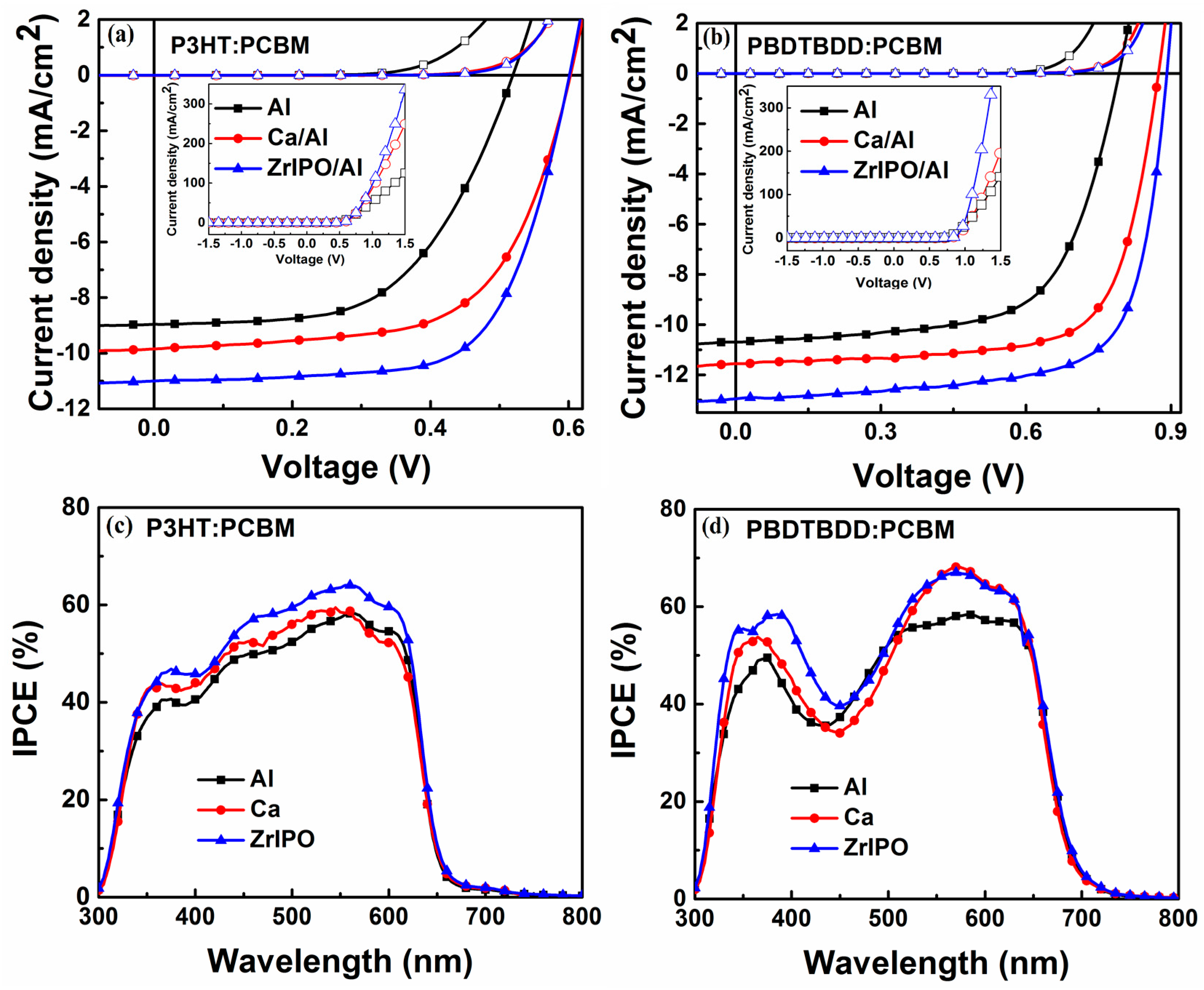
Figure 1. (a) Ultraviolet photoemission spectroscopy (UPS) spectra of as-prepared ZrIPO film. (left panel) the secondary edge at high binding energy region, related to work function, (right panel) the low-energy region, related to valence band maximum; (b) Determination of the optical bandgap using Tauc-plot for ZrIPO film.
Energies 11 00328 g001
Figure 2. (a) Molecular structures of Zr[OCH(CH3)2]4, P3HT, PBDTBDD and PCBM; (b) Device structure of the PSCs; (c) Highest occupied molecular orbital (HOMO) and lowest unoccupied molecular orbital (LUMO) energy levels of the materials involved in the PSCs.
Energies 11 00328 g002
Figure 3. Absorption spectra of ZrIPO film on quartz glass.
Energies 11 00328 g003
Figure 4. Atomic force microscope (AFM) images of (a,b) P3HT:PCBM and (c,d) PBDTBDD:PCBM photoactive layer without and with ZrIPO cathode modification layer on ITO/PEDOT:PSS substrates, respectively, with 10 μm × 10 μm scan size.
Energies 11 00328 g004
Figure 5. JV curves of the PSCs based on (a) P3HT:PCBM and (b) PBDTBDD:PCBM under the dark condition and under the illumination of AM1.5G, 100 mW/cm2; Input photon to converted current efficiency (IPCE) spectra of the PSCs based on (c) P3HT:PCBM; (d) PBDTBDD:PCBM.
Energies 11 00328 g005
Figure 6. The reflectance spectra of PSCs based on (a) P3HT:PCBM and (b) PBDTBDD:PCBM photoactive layer with bare Al, Ca/Al and ZrIPO cathode, respectively.
Energies 11 00328 g006
Table 1. Device parameters (averaged over 12 individual devices) of the PSCs with different cathode buffer layer (CBL) in the dark and under the illumination of AM1.5G, 100 mW/cm2.
Device Active LayerCathodeVoc (V)Jsc (mA/cm2)FF (%)PCE (%)Rs a (Ω cm2)
AP3HT:PCBMAl0.52 (±0.01)8.96 (±0.02)55.9 (±0.01)2.60 (±0.05)7.6 (±0.04)
BCa/Al0.60 (±0.01)9.85 (±0.03)62.4 (±0.02)3.69 (±0.03)3.5 (±0.03)
CZrIPO/Al0.60 (±0.01)11.0 (±0.01)67.7 (±0.01)4.47 (±0.02)2.8 (±0.02)
DPBDTBDD:PCBMAl0.79 (±0.01)10.7 (±0.02)64.8 (±0.02)5.48 (±0.04)12.5 (±0.05)
ECa/Al0.87 (±0.01)11.56 (±0.01)71.2 (±0.02)7.16 (±0.03)4.6 (±0.03)
FZrIPO/Al0.89 (±0.01)12.95 (±0.01)70.0 (±0.01)8.07 (±0.03)1.2 (±0.02)
a Series resistance (Rs) for PSCs in the dark is obtained at 1 V.

