Article

Numerical Investigation on the Heat Extraction Capacity of Dual Horizontal Wells in Enhanced Geothermal Systems Based on the 3-D THM Model

1
School of Petroleum Engineering, China University of Petroleum (East China), Qingdao 266580, China
2
Evaluation and Detection Technology Laboratory of Marine Mineral Resources, Qingdao National Laboratory for Marine Science and Technology, Qingdao 266100, China
3
Geotechnical Engineering Research Institute, Korea Institute of Civil Engineering and Building Technology, 283, Goyang-daero, Ilsanseo-gu, Goyang-si, Gyeonggi-do 10223, Korea
*
Authors to whom correspondence should be addressed.
Energies 2018, 11(2), 280; https://doi.org/10.3390/en11020280
Submission received: 29 November 2017 / Revised: 16 January 2018 / Accepted: 19 January 2018 / Published: 24 January 2018
(This article belongs to the Special Issue Geothermal Heating and Cooling)

Abstract

:
The Enhanced Geothermal System (EGS) constructs an artificial thermal reservoir by hydraulic fracturing to extract heat economically from hot dry rock. As the core element of the EGS heat recovery process, mass and heat transfer of working fluid mainly occurs in fractures. Since the direction of the natural and induced fractures are generally perpendicular to the minimum principal stress in the formation, as an effective stimulation approach, horizontal well production could increase the contact area with the thermal reservoir significantly. In this paper, the thermal reservoir is developed by a dual horizontal well system and treated as a fractured porous medium composed of matrix rock and discrete fracture network. Using the local thermal non-equilibrium theory, a coupled THM mathematical model and an ideal 3D numerical model are established for the EGS heat extraction process. EGS heat extraction capacity is evaluated in the light of thermal recovery lifespan, average outlet temperature, heat production, electricity generation, energy efficiency and thermal recovery rate. The results show that with certain reservoir and production parameters, the heat production, electricity generation and thermal recovery lifespan can achieve the commercial goal of the dual horizontal well system, but the energy efficiency and overall thermal recovery rate are still at low levels. At last, this paper puts forward a series of optimizations to improve the heat extraction capacity, including production conditions and thermal reservoir construction design.

1. Introduction

1.1. Background

Increasing the supply of local and renewable energy has become a central issue across society, which highlights the necessity to re-evaluate all alternative energy sources, particularly those widely distributed throughout the country [1]. Geothermal energy is a low-carbon and recyclable renewable energy, with the features of large reserves, wide distribution and environmental friendliness. Compared to hydrothermal geothermal resources, most of the geothermal energy is stored in hot crystalline rocks with no or little fluid in a depth range of about 3−10 km, at a temperature between 150 and 650 °C [2]. This is often called hot dry rock (HDR).
The Enhanced Geothermal System (EGS) represents the key technology of the HDR heat development project, with a research history of more than 40 years [3]. It requires water to be circulated from injection well to production well, via an artificial thermal reservoir constructed by hydraulic fracturing [4]. In general, the produced energy from HDR is used to generate electricity or supply heat. According to a report by MIT about the future of geothermal energy, EGS and other unconventional geothermal resources will have provided 100,000 megawatts of base load generating capacity by 2050, accounting for 10% of total value of U.S. [1,5].
Field testing of EGS worldwide began in 1974 at the Fenton Hill HDR geothermal project in the United States [6,7], demonstrating that enhanced geothermal systems are technically feasible. However, how to establish an artificial heat reservoir at commercial scale and develop the thermal energy cost-efficiently is still a significant measure to evaluate the promotion and application of EGS. Nowadays, the limitation of economic feasibility lies in low water production and excessive high water flow impedance and water loss level [1,8]. In 2005, based on the determination data of EGS project in the Desert Peak, Sanyal S. K. et al. [9] calculated the electric power generation and analyzed the prospect of EGS application, according to the first and second laws of thermodynamics. Zeng Y.C. et al. [10] adopted the geological data of Well DP23-1 to investigate the HDR thermal potential, by which the fractured reservoir is equivalent to a homogeneous porous medium reservoir with the water circulation through two horizontal wells. However, the actual energy yield and water circulation efficiency cannot be achieved owing to the neglect of fractures. Cao et al. [11] simulated the heat extraction capacity of EGS using an ideal vertical well model based on the assumption of local non-thermal equilibrium, yet the existence of fractures is still not taken into consideration. Tang [12] studied the distribution of temperature field and the law of energy utilization with a two-dimensional natural fracture-fault model. In present period, the models applied on heat extraction capacity evaluation are too simplified to reflect the actual formation. In addition, the combination of multi-physical and multi-scale effects involved in the EGS operation is not taken into account.
Since the 1980s, based on the Biot consolidation theory, Noorishad et al. [13] established a thermal-hydraulic-mechanical field (THM) coupled model in order to study the underground disposal of nuclear waste. Subsequently, numerous researchers have applied a fluid-rock coupled mathematical model to the EGS mass and heat transfer process. Regarding the thermal reservoir as a single porosity equivalent porous medium, Jiang et al. [14,15] studied the thermal-hydraulic process of an EGS reservoir using the 3-D transient model, but the model did not consider the effect of the mechanical field. Lei et al. [16] and Rutqvist [17] respectively established a THM coupled model and solution method to realize the numerical simulation of the EGS production process. They developed TOUGH2 (Lawrence Berkeley National Laboratory (LBNL), Berkeley, CA, USA) software, while ignoring the complexity of fractured reservoir. Rinaldi et al. [18] simulated a THM coupled EGS project and analyzed the possibility of inducing artificial fractures and natural fractures by TOUGH-FLAC simulator. The mature commercial software commonly used in EGS heat exploitation numerical simulation is listed in Table 1.

1.2. Research Objectives

In this paper, the thermal reservoir is treated as a fractured porous medium composed of matrix rock and a discrete fracture network. Using the local thermal non-equilibrium theory, a set of coupled THM equations are formulated as the mathematical model for the EGS thermal recovery process. Furthermore, the ideal 3D numerical model of EGS exaction by horizontal well is created with the commercial software COMSOL Multipysics (5.3, COMSOL Co. Ltd., Stockholm, Sweden) Subsequently, the model is applied to predict the actual problems encountered in EGS heat exaction, such as operating performance, utilization efficiency and service life.

2. THM Coupled Model

The two-dimensional EGS thermal recovery process numerical model [19] is extended to three-dimensional space. Considering local thermal non-equilibrium, the model adopts two energy equations to respectively describe the temperature field in the rock matrix and the fluid existing in fractures, which can conveniently deal with the actual rock-fluid heat transfer during the heat recovery.

2.1. The Governing Equation

The governing equations of the THM coupled mathematical model can be described as follows:

2.1.1. Rock Mass Stress Field Governing Equation

I Matrix rock stress/displacement field equation
The equilibrium equation in the terms of stress tensor can be written as:
σ i j , j + F i = 0
Based on the linear stress-strain constitutive law, the deformation equation of the rock matrix is as follows:
E 2 ( 1 + ν ) u i , j j + E 2 ( 1 + ν ) ( 1 2 ν ) u j , j i α B p , i α T E ( 1 2 ν ) T s , i + F i = 0
where, σ i j is stress tensor; u is displacement; F i is the body force per unit volume in the i-coordinate (i = x, y, z in 3D); E is elastic modulus; ν is Poisson’s ratio; p is hydraulic pressure; α B is the Biot’s constant, whose value is less than 1; T s is rock temperature; α T is thermal expansion coefficient; α B p , i and α T E T s , i / ( 1 2 ν ) reflect hydraulic pressure and thermal- mechanical respectively.
II Fracture deformation equation
The deformation equation of the rock mass fracture can be expressed as:
u n = σ n / k n ,   u s 1 = σ s 1 / k s ,   u s 2 = σ s 2 / k s
σ n = σ n α B p ,   σ s 1 = σ s 1 ,   σ s 2 = σ s 2
where, k is fracture stiffness; u is displacement of fracture; σ is Effective stress of fracture; The subscripts n, s 1 and s 2 denote the normal and tangential directions, respectively.

2.1.2. Rock Mass Flow Field Governing Equation

I Matrix rock flow field equation
The flow of water in deformable porous media is described by the following mass balance equation:
S p t + · v = e t + Q
Supposing that the flow obeys Darcy's law, the water flow rate v can be written as:
v = κ r η ( p + ρ g z )
where, t represents time; v is water flow rate in rock mass; κ is rock permeability; η is dynamic viscosity of fluid; S is storage coefficient of rock mass; e is volumetric strain of rock mass; Q is source-sink term of the seepage process.
II Fracture flow field equation
The mass balance equation in discrete fractures can be described as:
d f S f p t + τ · ( d f κ f η p ) = d f e f t + Q f
Q f = κ f η p n
where, S f is storage coefficient of fracture; κ f is fracture permeability; d f is fracture width; Q f is flow exchange between rock mass and fracture surface: n indicates the normal direction of fracture surface; e f is volumetric strain of fracture surface; τ represents derivative along the tangential direction of fracture.

2.1.3. Rock Mass Temperature Field Governing Equation

I Matrix Rock Temperature Field Equation
The energy balance equation for heat transfer in porous rock matrix is given as
C s ρ s T s t = λ s 2 T s + W
where, ρ s is rock density; λ s is thermal conductivity of rock mass; C s is heat capacity of rock block; W is heat source.
Due to the low porosity, the water flow velocity in the matrix block is low, in which case the water temperature can be considered to be equal to the rock temperature, thus the convection in the pores of the rock mass is not taken into account.
II Fracture water temperature field equation
The energy balance equation for heat transfer and advection in the discrete fracture is written as
d f ρ f C f T f t + d f ρ f C f · v f τ T f = d f τ · ( λ f τ T f ) + W f
where, ρ f is water density; C f is heat capacity of water; λ f is thermal conductivity of water; v f is water flow velocity in fracture; T f is water temperature in fracture; W f indicates heat absorbed from matrix block by water on fracture surface.

2.2. Local Thermal Non-Equilibrium Theory

Based on the theory of local thermal non-equilibrium, there is a local temperature difference between the heat transfer fluid and matrix rock mass. Assuming that the heat exchange obeys the Newton heat transfer equation, the heat transfer from the matrix rock to fracture water at the boundary could be expressed by the convection coefficient as a form of the Newton’s law [20]:
W f = h ( T s T f )
where, h is the convection coefficient.

2.3. Multiphysics Coupling Characteristics

2.3.1. TH Coupling Characteristics of Work Fluid

At high temperature and high pressure, the water density ρ f is generally expressed as a function of temperature and pressure, instead of a constant [21].
1 / ρ f = 3.086 0.899017 ( 4014.15 T ) 0.147166 0.39 ( 658.15 T ) 1.6 ( p 225.5 ) + δ
where, T is absolute temperature of water; δ is a function of water temperature and pressure, generally not exceeding 6% of 1 / ρ f .
In addition, the water temperature has a great influence on the water dynamic viscosity η , η = υ ρ f , in which υ is the kinematic viscosity coefficient of water calculated by empirical formula [22]:
υ = 0.01775 1 + 0.033 T f + 0.000221 T f 2
The density and viscosity of water are both related to temperature. Temperature exchange directly affects the seepage and heat transfer process, and the interaction between the two is a strong coupling relationship.

2.3.2. HM Coupling Characteristics in Fractured Surface

Hydraulic fracturing is a significant method of reservoir stimulation [23]. The induced fractures are the main flow channels of the heat transfer fluid. Mechanical behavior in the EGS thermal recovery process will give rise to severe deformation of the fracture structures in rock mass. As the most important parameter to ensure the feasibility of EGS [24], the fracture permeability will change with the variation of stress and strain. The fracture permeability is intensely related to the fracture thickness or aperture, while the aperture depends on the effective normal stress. Therefore, the permeability variation can be described as [25,26]
k f = k 0 exp ( α σ n )
where, k f is fracture permeability; k 0 is initial permeability in the case of σ n = 0 ; σ n is normal stress of fracture surface; α is influence coefficient, depending on the rock fracture state.
In order to simplify the calculation, the matrix permeability is regarded as a constant.

3. EGS Horizontal Well Geothermal Exploitation Model

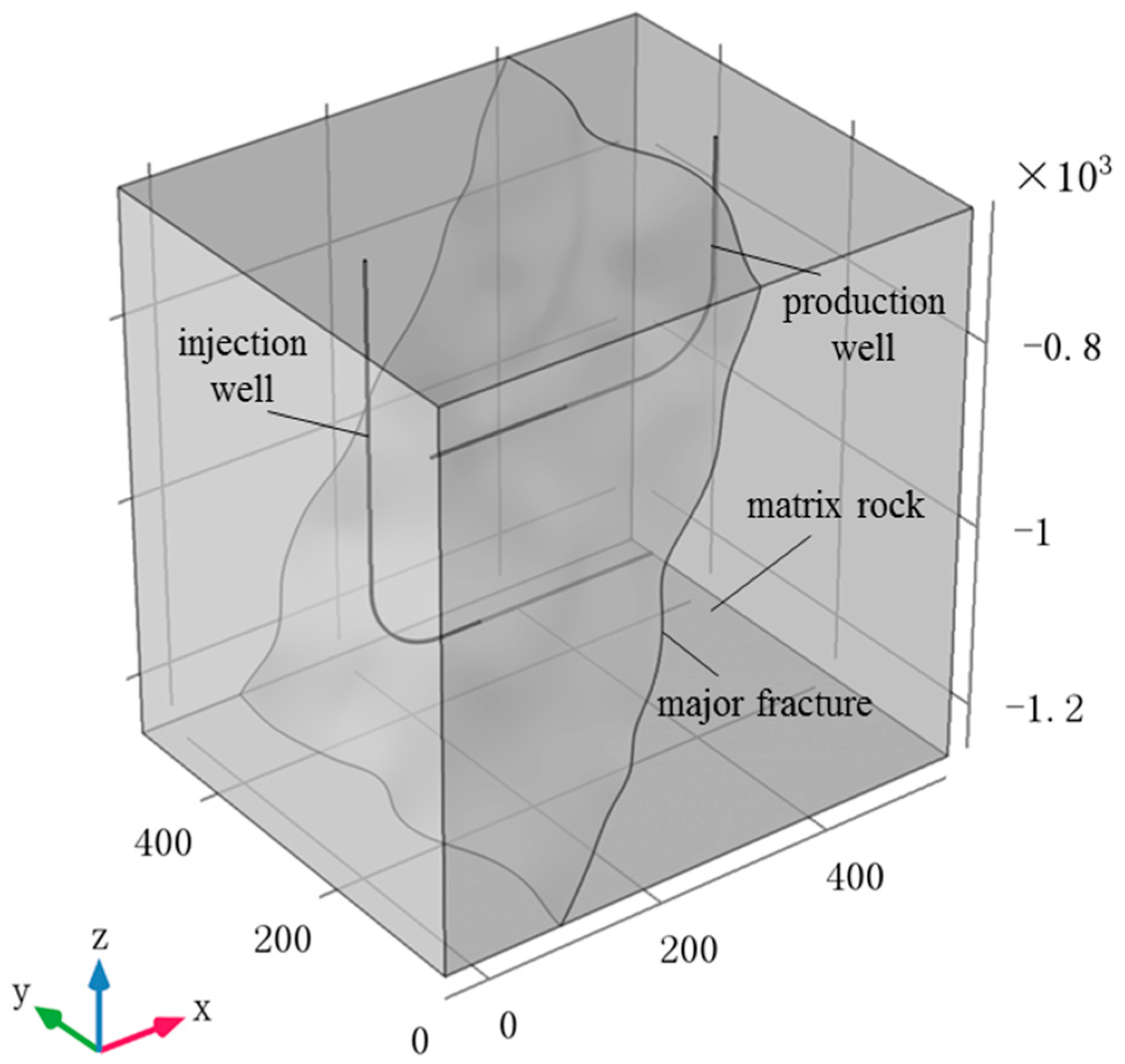
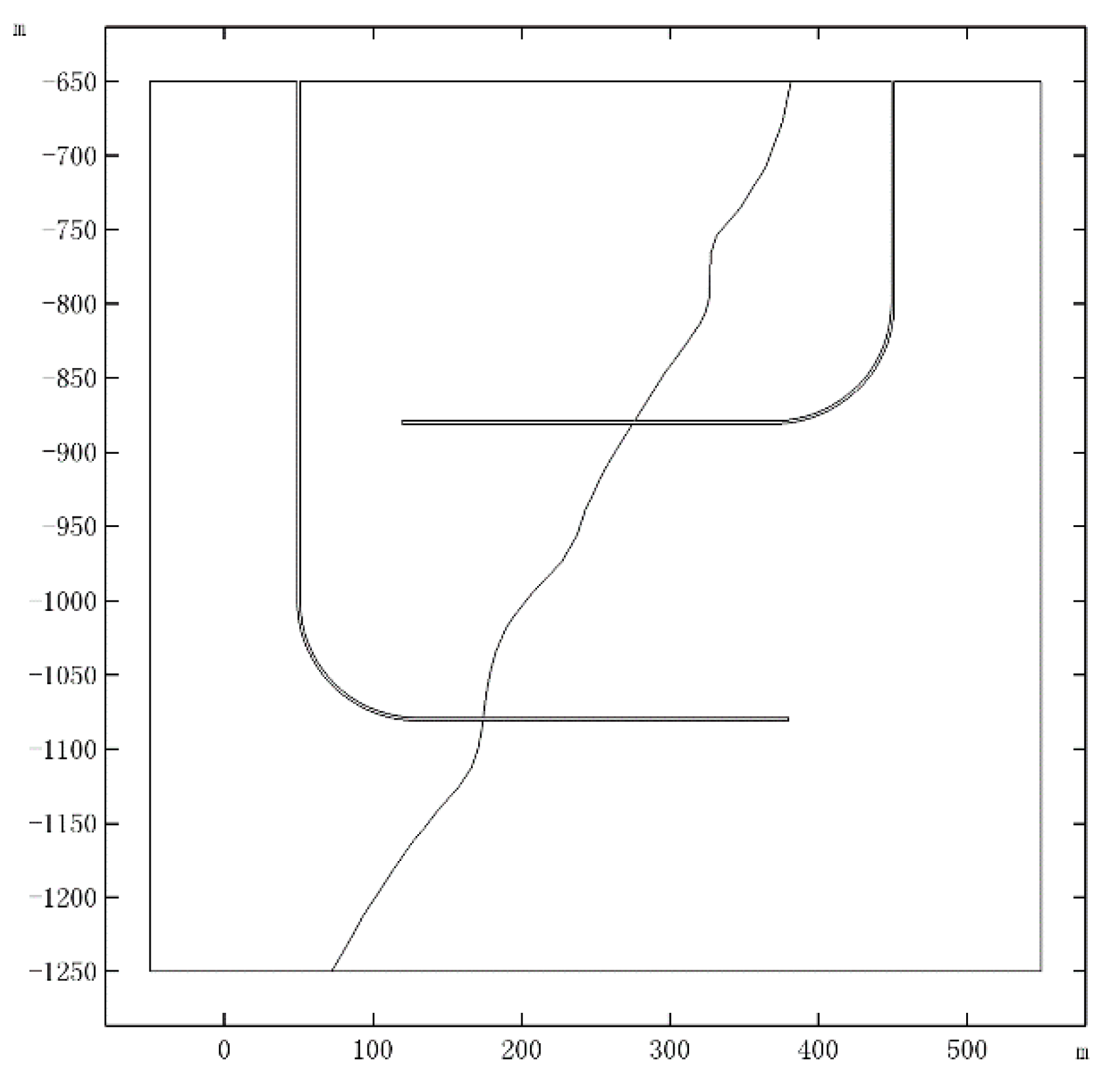
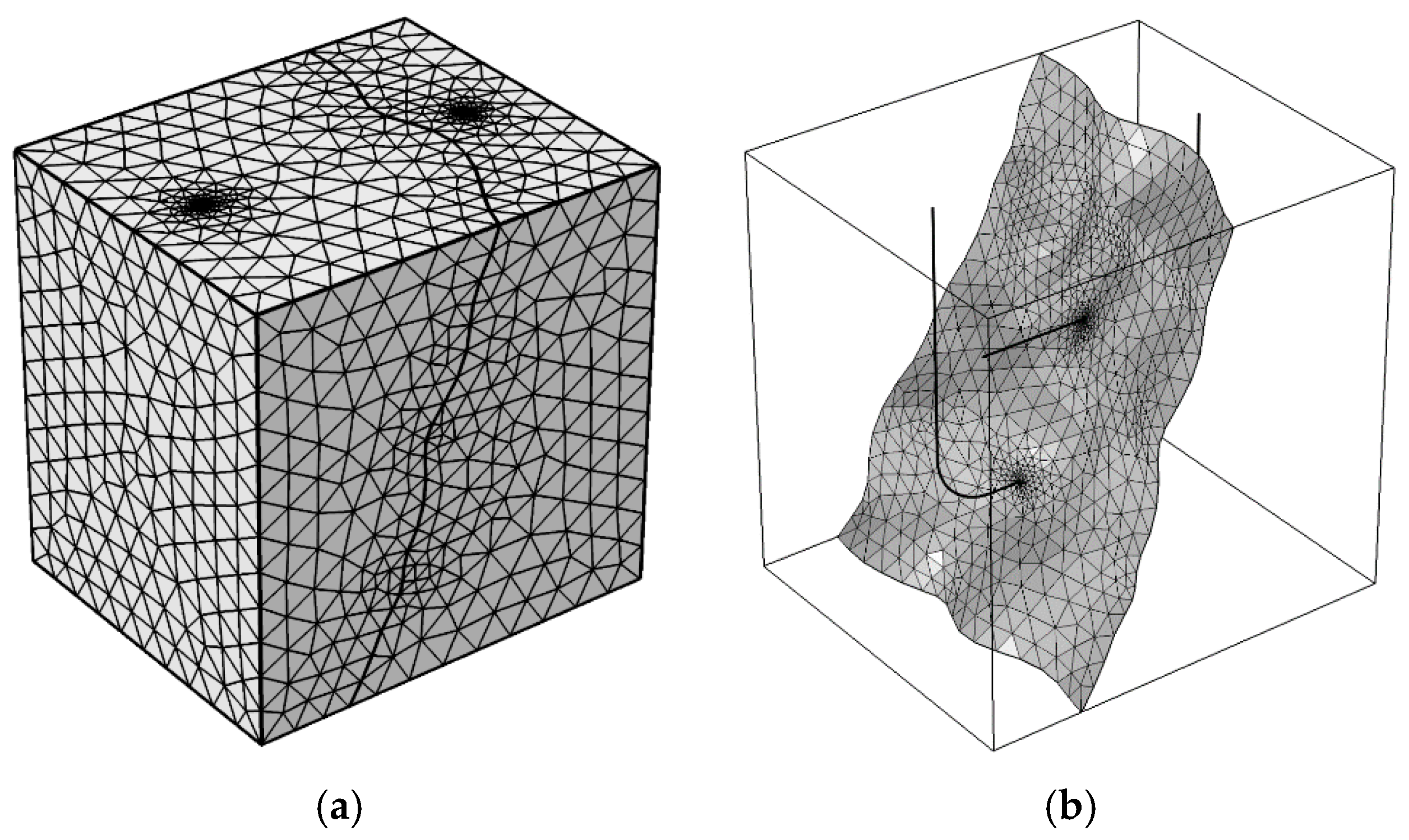
3.1. Computational Model

The characteristic required for EGS reservoir rock is a large quantity of open connected fractures, which must be considered in numerical simulation. At present, the rock mass with densely distributed fractures is generally treated by equivalent method and simplified by continuum medium theory, and the discrete model is used to deal with large faults or main penetrating fractures [27]. It has also been shown that in some circumstances most of the heat transfer fluid in the EGS may migrate directly from the injection well to the production well via only one or a few major flow channels [28]. Since the direction of the natural and induced fractures are generally perpendicular to the minimum principal stress in the formation, as an effective stimulation approach, horizontal well production could increase the contact area with the thermal reservoir significantly [29].
In this work, an ideal dual horizontal well EGS exploitation model is established as shown in Figure 1, with a penetrating fracture in the reservoir. In order to examine the accuracy of the proposed model and its numerical implementation in the fracture, a 2D single fracture model is studied in our previous work [19].
It is assumed that the reservoir is located at 1150 m underground with a size of 600  m × 500  m × 600  m . Regarding the direction along the horizontal wells as x, the vertical well section as z, and the direction y is perpendicular to x and z. The position of injection well and production well is respectively located at x = 50, z = −1080 and x = 450, z = −880, as shown in Figure 2. The radius of the wellbore is 0.1 m, and the horizontal section length is 250 m. The model is solved by commercial finite element software COMSOL Multiphysics, and the finite element model used in the calculation is shown in Figure 3.

3.2. Computational Parameters

The reliability of numerical simulation depends on the selection of computational parameters. Due to the lack of corresponding test data, the parameters are selected by assumptions and reference to the existing numerical simulation. The main material parameters adopted in the model are shown in Table 2.
Equation (13) is used to describe the coupled characteristics of hydraulic and mechanical behavior in the fracture surface. The influence coefficient α is simply taken as 0.1 × 10 Pa 1 for the convenience of analysis. When subjected to tensile stress (tensile stress is positive), the permeability increases with the opening of the fracture; and vice versa, under compressive stress, the permeability decreases with the closure of fracture surface.

3.3. Initial and Boundary Conditions

The above model is used to simulate the entire process of EGS exploitation from water injection to operation. The boundary conditions and initial conditions are as follows:
(1) Flow field
Injection well water pressure is defined as 21 MPa, and production well water pressure is set to 5 Mpa; all external boundaries are impermeable, and it is assumed that reservoir pressure has reached a steady state before water injection.
(2) Temperature field
The injection well temperature is consistent with water temperature inside the well, taken as 20 °C. The boundaries around the model are thermal insulating. The initial temperature of rock mass and fracture water within the reservoir is both 200 °C.
(3) Stress field
In the stress field simulation, the external boundaries around the model are all set to displacement constraint boundary. Compared with the in situ stress, more attention is paid to the disturbance of rock mass stress field caused by the development and operation of EGS. Therefore, without considering the influence of in situ stress field, this work only investigates the effect of high pressure water injection and geothermal recovery on the stress field of fractured rock mass. It is conducive to understand the coupling effects between the seepage/temperature field and the variation of stress and displacement in rock mass.
The model is solved by transient simulation. The total computation length is 50 years (unit: a) and the step length is 60 days (unit: d).

4. Thermal Recovery Evaluation System

Garnish and Evans [30] proposed evaluation parameters and requirements for the commercial exploitation of thermal reservoir: (1) the average reservoir temperature should not be lower than 190 °C, or it drops less than 10% of the original reservoir temperature after 15−20 years of production without reservoir reconstruction; (2) when water production rate is 100 kg/s, water loss is less than 10%; (3) reservoir reconstruction volume is greater than 2 × 10⁸ m3; and (4) effective heat exchange area is larger than 2 × 10⁶ m2. When the injection water temperature is 60 °C and the water injection rate is 50 kg/s, the commercial dual horizontal well system aims to generate heat and electricity of 25 MW and 3.5 MW respectively. Sanyal and Buter [9] put forward the three most important indicators to evaluate of thermal reservoir performance, including temperature production profiles, net power generation profiles and thermal recovery rate.

4.1. Thermal Recovery Lifespan

Although geothermal energy is considered to be a renewable one, its project lifespan is commonly 20−30 years. In general, the fractured reservoir will take nearly 100 years to recover, because of a drastic decrease in temperature during the heat exaction [31]. Therefore, it is necessary to limit the geothermal energy exploitation to maintain sustainable development. Previous studies have demonstrated that the best time to stop thermal recovery is when the average reservoir temperature is decreased by 10 °C [2] or the output temperature of the production well is reduced by 10% [32].

4.2. Average Outlet Temperature

The average outlet temperature of the dual horizontal well system can be calculated by outlet water temperature from fracture and matrix rock:
T o u t = L u f d f T f d L + Γ u T s d Γ L u f d f d L + Γ u d Γ
where, u f and u are outlet flow rate from fracture and matrix rock respectively, m/s; d f is fracture width, m; T f and T s are outlet water temperature from fracture and matrix rock respectively, K; L represents the length integral of the output along fracture; Γ represents the surface integral of the output along the matrix rock block.

4.3. Heat Production

The heat production of the dual horizontal well system is calculated as [33]:
W h = q ( h p r o h i n j )
where, h i n j is injection specific enthalpy, kJ/kg; h p r o is production specific enthalpy, kJ/kg; q is total production rate, kg/s.
After long-term exploitation, the heat transfers between wellbore fluid and surrounding rock can be neglected. In other words, the flow in wellbore is an isoenthalpy process [33].

4.4. Energy Efficiency

The system energy efficiency η is defined as the ratio of total production energy to total consumed energy:
(1) Total production energy
Assuming that all the produced heat is used to generate power, based on the second law of thermodynamics, the useful work transformed is expressed as:
q ( h p r o h i n j ) ( 1 T o / T p r o )
According to the [10], the utilization efficiency coefficient of conversion from useful work to electric energy is 0.45, then the calculation formula of power generation is as follows:
W e = 0.45 q ( h p r o h i n j ) ( 1 T o / T p r o )
where, T o is reinjection temperature of injection well, absolute temperature.
(2) Total consumed energy
The total energy consumption W p mainly includes energy consumption of injection pump W p 1 and suction pump W p 2 . When the energy consumption caused by pipeline friction and fluid internal friction is ignored, the calculation formula of energy consumption of injection pump, suction pump and total energy consumption are as follows:
W p 1 = p i n j d V = q ( P i n j ρ g h 1 ) / ( ρ η p )
W p 2 = p p r o d V = q ( ρ g h 2 P p r o ) / ( ρ η p )
W p = W p 1 + W p 2 = q ( P i n j P p r o ) ρ g q ( h 1 h 2 ) ρ η p
where, d V is volume of injected water per second, m3/s; h 1 is depth of injection well, m; h 2 is depth of production well, m; η p is pump efficiency.
(3) System energy efficiency
Based on heat production, the energy consumption η h is as follows:
η h = W h W p = ρ η p ( h p r o h i n j ) ( P i n j P p r o ) ρ g ( h 1 h 2 )
Based on power generation, the energy consumption η e is as follows:
η e = W e W p = 0.45 ρ η p ( h p r o h i n j ) ( 1 T o / T p r o ) ( P i n j P p r o ) ρ g ( h 1 h 2 )

4.5. Heat Recovery Rate

(1) Local heat recovery rate
Local heat recovery rate γ L is defined as [14]:
γ L ( t ) = T r T s ( t ) T r T i n j
where, T r and T s ( t ) are rock temperature at the initial time and the time t respectively, K; T i n j is temperature of the injected fluid, K.
(2) Overall heat recovery rate
Overall heat recovery rate γ refers to the ratio of the thermal energy exploited by EGS at time t to the total energy available in thermal reservoir.
γ ( t ) = V γ L ( t ) d V V d V

5. Results and Discussions

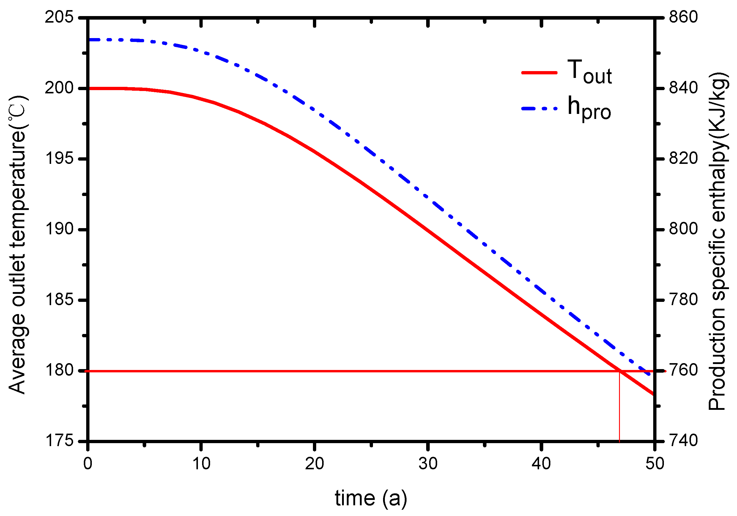
5.1. Production Temperature and Thermal Recovery Lifespan

According to Equation (15) and EN1434-2007 heat meter (ICS 17.200.10, British Standard, Technical Committee), the average outlet temperature and specific enthalpy of production is calculated respectively. The evolution of outlet temperature T o u t and production specific enthalpy h p r o are plotted in Figure 4. The result shows that the whole exploitation process can be divided into two stages: steady stage and decline stage. At the beginning of operation, the steady stage lasts about 10 years. The outlet water temperature maintains at 200 °C (initial reservoir temperature) and the corresponding specific enthalpy remains at 853 kJ/kg. At the decline stage, the outlet water temperature drops from 200 °C to the lowest of 180 °C. In addition, the production specific enthalpy decreases from 853 kJ/kg to the lowest of 758 kJ/kg accordingly.
When the water temperature drops by 10%, that is, when the temperature of the production well drops to 180 °C, the exploitation process should be stopped. Therefore, as shown by the red lines, the entire lifecycle of the project is about 47 years, which can meet the commercial target of a thermal recovery lifespan of 15−20 years.

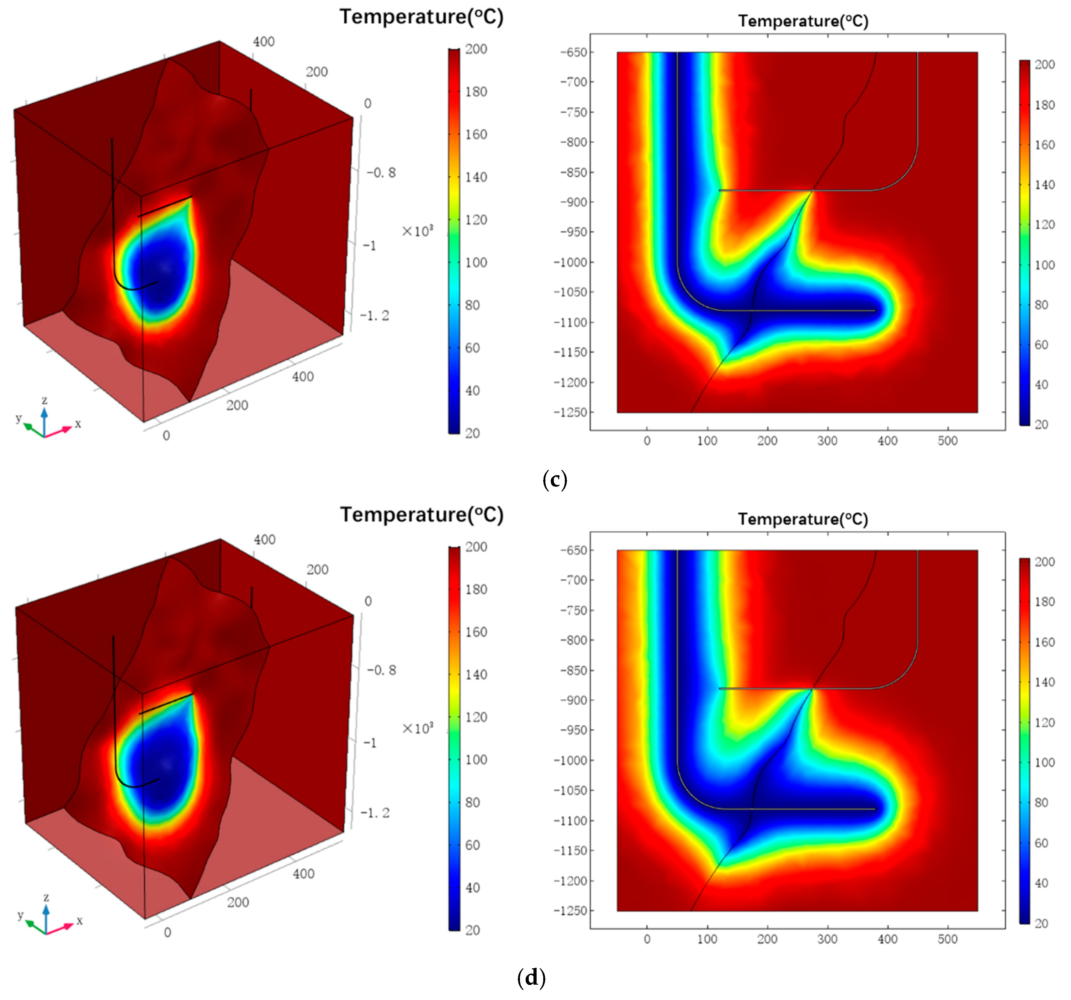
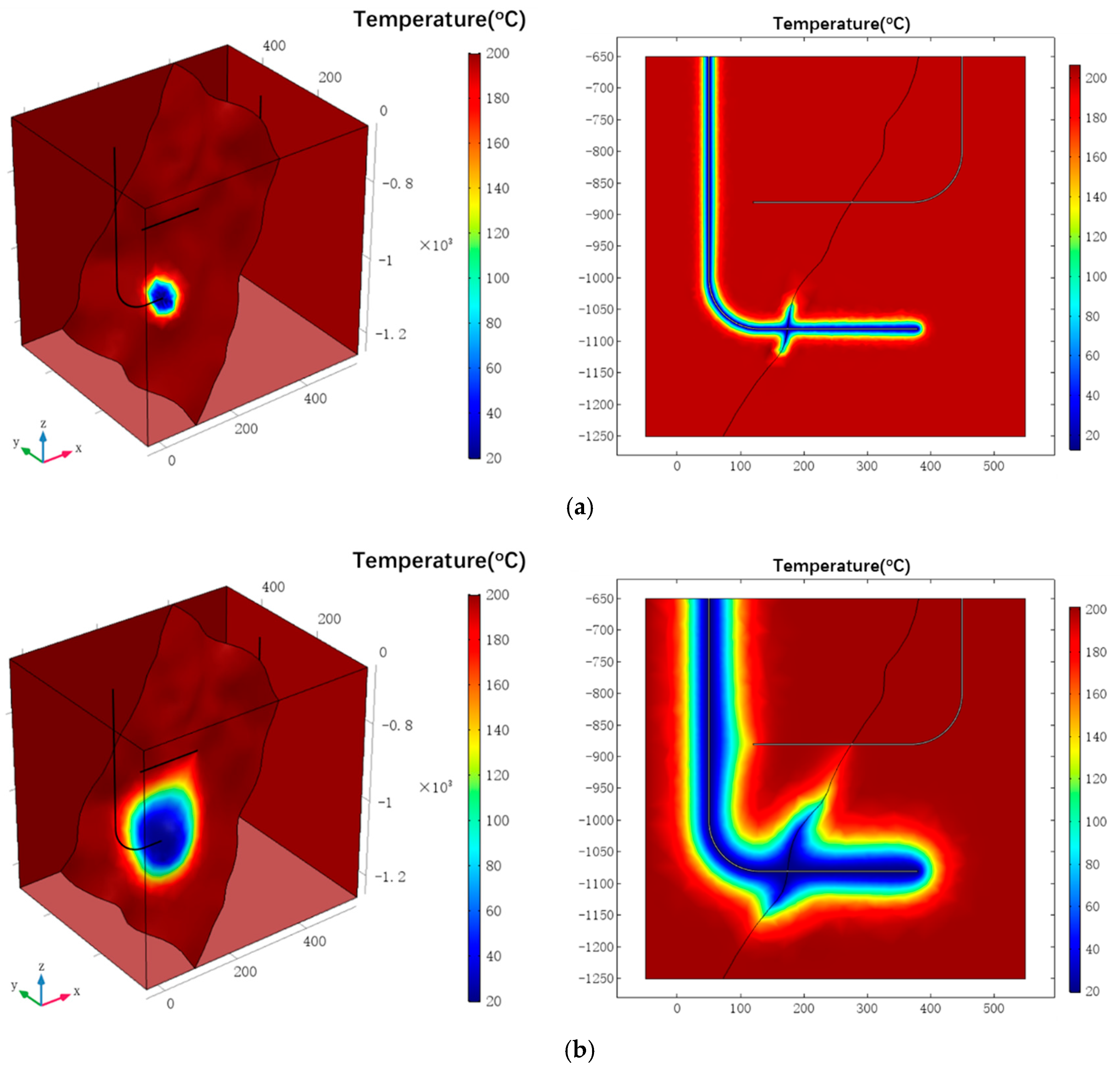
5.2. Distribution of Temperature

Figure 5 describes the temperature variations in the EGS reservoir at different times (t = 1a, 15a, 30a, 45a) obtained from COMSOL Multiphysics. In the initial stage, with the injection of low-temperature water, heat exchange occurs between matrix rock and fracture water, and the temperature of fracture water rises rapidly, the temperature of rock mass at fracture surface decreases quickly. With the process of thermal recovery, due to the heat conduction, the temperature of rock mass far away from the fracture surface also decreases gradually, forming a low-temperature zone. However, the temperature of the rock mass near the production well almost has no change, so that the system can guarantee the sustained and stable output of heat. With the increase of thermal recovery lifespan, the low-temperature zone in the reservoir will expand, and finally reach the production well, and the water temperature will gradually decrease.
It can be clearly seen from the figure that the low-temperature zone near the fracture channel expands faster compared to the rock matrix region, because the penetrating fractures form the main water flow region with higher water velocity and more obvious convection effect. As is known from the analysis, the EGS thermal performance depends strongly on the fluid flow in the thermal reservoir. The optimization of the flow field distribution in the thermal reservoir can improve the thermal recovery performance of EGS. In further work, the optimization will be conducted in terms of well type and well pattern. According to the actual geological structure, select the appropriate well type, well quantity and reasonable injection-production ratio. Based on the fracture orientation, adjust the direction of the line connecting injection well and production well.

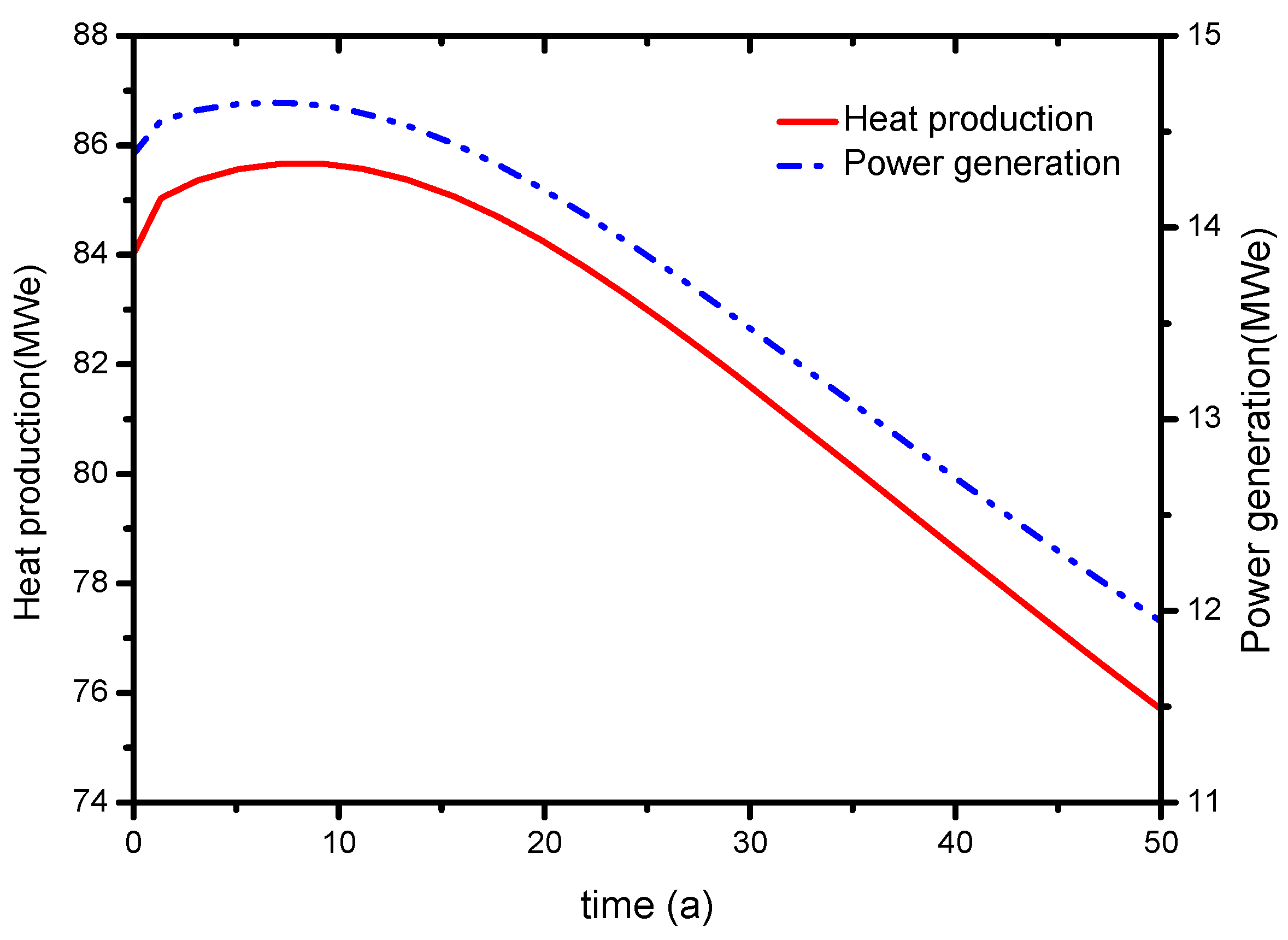
5.3. Heat Production and Power Generation

Figure 6 shows the evolution of heat production and power generation over time, calculated by Equations (16) and (18). Since the total production rate has not yet reached the maximum in the initial stage, the variation trend of both is increased at first and then gradually decreased. At the initial stage of exploitation, there is a highest value, heat production and power generation of 85.6 MWe and 14.6 MWe respectively. With the gradual reduction of the temperature, the heat production drops from 85.6 MWe to 77 MWe and the power generation decreases from 14.6 MWe to 12.2 MWe. The commercialization goal of the dual horizontal well system is to generate 25 MWe and 3.5 MWe of heat and power, respectively. Therefore, compared with the target, heat production and power generation meet the commercial requirements.

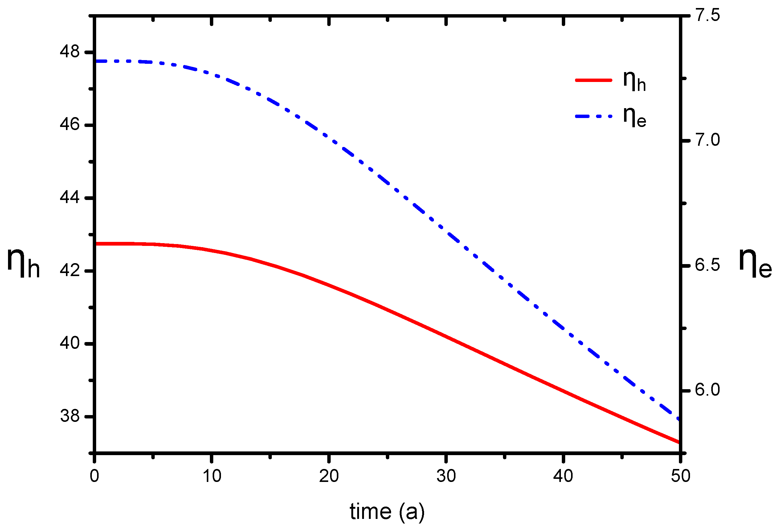
5.4. Energy Efficiency

According to Equations (22) and (23), Figure 7 shows the evolution of system energy efficiency η h and η e . As can be seen from the figure, both the energy efficiency based on heat production and power generation decrease with the progress of exploitation. During the entire production process, η h drops from 43 to 37, and η e declines from 7.3 to 5.8. From an economic point of view, energy efficiency η h and η e can only balance the cost consumption during production, including drilling and hydraulic fracturing. However, the results are based on flash steam power plants, which requires hydrothermal fluids above 182 °C [34]. Given that advance in geothermal power generation technology, e.g., binary cycle power plants, lower temperature (85−175 °C) production will be utilized, so that the system energy efficiency will be improved obviously.

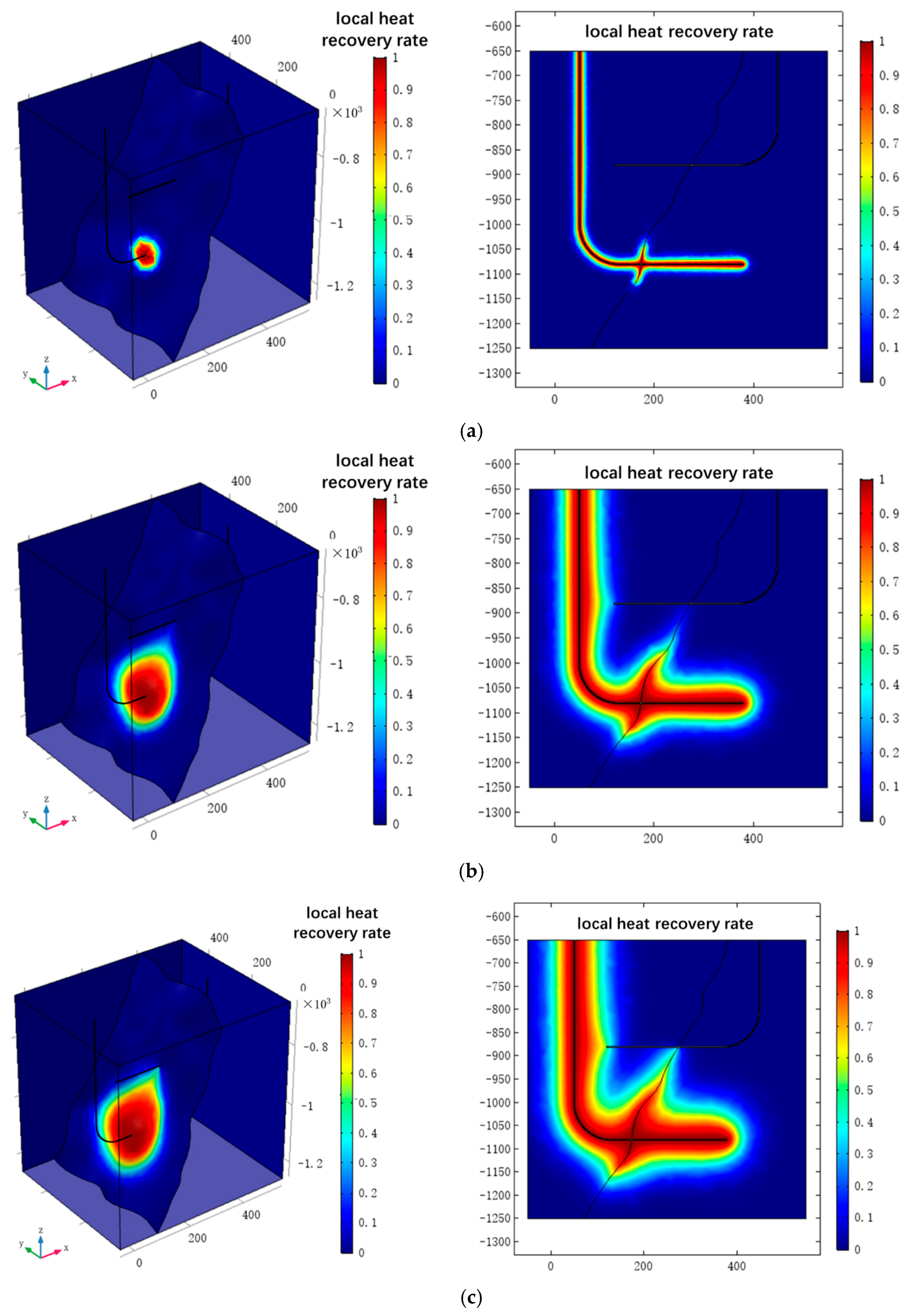
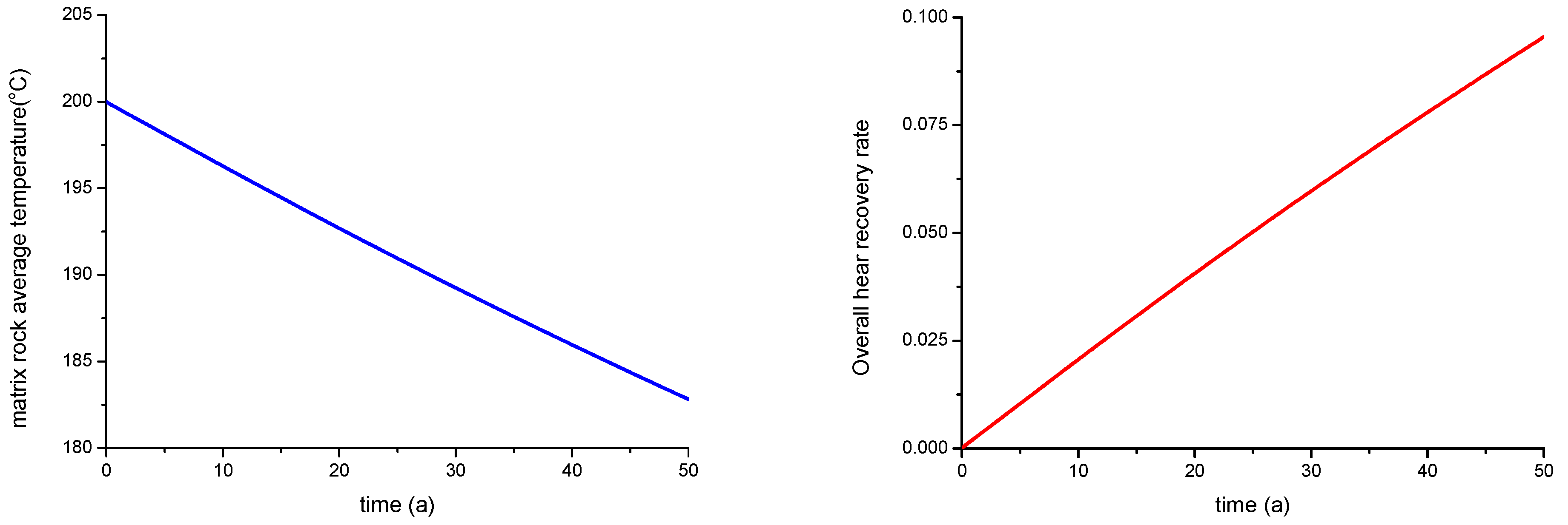
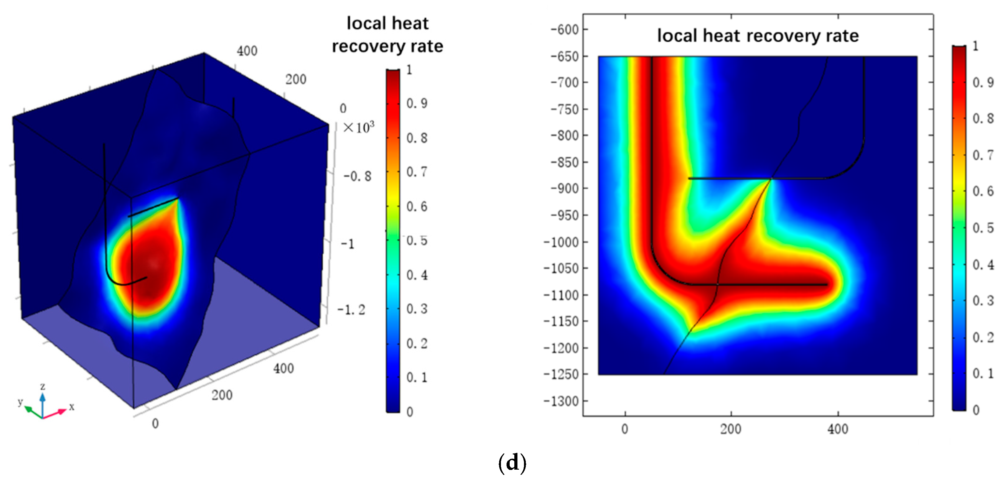
5.5. Heat Recovery Rate

The local heat recovery rate is obtained with Equation (24) by COMSOL Multiphysics. Figure 8 shows the distribution of the local heat recovery rate at different times in the EGS reservoir. At the initial time, heat exchange occurs between the matrix rocks and the low-temperature water, and the temperature of the rock matrix decreases rapidly. The local heat recovery rate near the injection well is close to 1, indicating that with the development of exploitation, the rock matrix supplies less and less to the circulating water. Therefore, the thermal recovery far from wellbore should be improved as much as possible if thermal recovery performance is optimized. At the 45th year of production, the production well temperature has reached the limited temperature. However, it is observed from the profile that only the recovery rate near the injection well is high, while it is relatively low in most areas, especially near the production well. Therefore, in order to improve the thermal recovery in a wide range of production wells, it can be solved by well pattern optimization.
Figure 9 indicates the evolution of the overall heat recovery rate, calculated according to Equation (25). From the overall heat recovery effect evaluation of the dual horizontal well system, the overall thermal recovery rate and the matrix rock average temperature both have a linear relationship with time, because the temperature drop has not reached the upper and lower boundaries, which can maintain a constant heat supply. It can be inferred that the overall thermal rate growth will decline over time when the temperature drop spreads to the upper and lower boundaries. After 45 years of operation, the exploited heat energy accounts for a small proportion of total available thermal energy in reservoir, only 8%. That is, a large amount of thermal energy still remains in the reservoir, which need further optimization of production conditions and thermal reservoir construction design.

6. Conclusions

In this paper, the thermal reservoir is treated as a fractured porous medium composed of matrix rock and discrete fracture network. Using the local thermal non-equilibrium theory, a THM coupled mathematical model and the ideal 3D numerical model are established for EGS heat extraction capacity evaluation.
(1)
In order to recover the drastic decrease of temperature in fractured reservoir, the entire lifecycle of the model described here is about 45 years, which can meet the commercial target with thermal recovery lifespan of 15−20 years.
(2)
The EGS heat extraction depends strongly on the fluid flow in the thermal reservoir. The low-temperature zone near the fracture channel expands faster compared to the rock matrix region, because the penetrating fractures form the main water flow region with higher water velocity and more obvious convection effect.
(3)
The variation trend of heat production and power generation is both increased at first and then gradually decreased, and they meet the commercial requirements. However, based on flash steam power plants, energy efficiency and heat recovery rate are still at a fairly low level.
(4)
A large amount of thermal energy still remains in the reservoir, which needs further optimization of production conditions and thermal reservoir construction design. According to the actual geological structure, selection of the appropriate well type, well quantity and reasonable injection-production ratio is necessary. Based on the fracture orientation, adjustment the direction of the line connecting injection well and production well is necessary. Given that the advance in geothermal power generation technology, e.g., binary cycle power plants and lower temperature production will be utilized, the system energy efficiency will be obviously improved.

Acknowledgments

This study was jointly supported by the National Natural Science Foundation of China (Grant NO. 51774317, Grant NO. 51722406 and Grant NO. 61573018), the Fundamental Research Funds for the Central Universities (Grant No.18CX02100A) and Evaluation and Detection Technology Laboratory of marine mineral resources, Qingdao National Laboratory for Marine Science and Technology (Grant No. KC201702) and National Science and Technology Major Project (Grant NO.2016ZX05011004-004). We are grateful to all staff involved in this project, and also wish to thank the journal editors and the reviewers whose constructive comments improved the quality of this paper greatly.

Author Contributions

Z.S., Y.X. and J.Y. and conceived and designed the numerical investigation; Z.S., Y.X. and L.Z. created the numerical model; J.Y. and K.Z. summarized the thermal recovery evaluation system; Z.S. and J.Y. examined the accuracy of the proposed model; K.Z. and Y.X. analyzed the result; Z.S. and L.Z. contributed analysis tools; Y.X. and X.Z. wrote the manuscript; X.Z., T.W. and C.J. make a great contribution to the revision of manuscript.

Conflicts of Interest

The authors declare no conflict of interest.

Nomenclature

The following terms are used in this manuscript:
σ i j stress tensor (Pa)
u displacement (m)
F i body force per unit volume in the i-coordinate(i = x, y, z in 3D) (Pa)
E elastic modulus (Pa)
ν Poisson’s ratio
p hydraulic pressure (Pa)
α B Biot’s constant
T s rock temperature (K)
T f water temperature in fracture (K)
α T thermal expansion coefficient
kfracture stiffness (Pa/m)
u n normal displacement of fracture (m)
u s tangential displacement of fracture (m)
σ effective stress of fracture (Pa)
ttime (s)
η dynamic viscosity of fluid (Pa·s)
v water flow rate (m/s)
k r rock permeability (m2)
k f fracture permeability (m2)
e volumetric strain of rock mass
e f volumetric strain of fracture surface
S storage coefficient of rock mass (1/Pa)
S f storage coefficient of fracture (1/Pa)
Q source-sink term of the seepage process (1/s)
Q f flow exchange between rock mass and fracture surface (m/s)
d f fracture width (m)
ρ s rock density (kg/m3)
ρ f water density (kg/m3)
λ s thermal conductivity of rock mass (W/m/K)
λ f thermal conductivity of water (W/m/K)
C s heat capacity of rock block (J/kg/K)
C f heat capacity of water (J/kg/K)
W heat source (W/m3)
W f heat absorbed from matrix block on fracture surface (W/m2)
v f water flow velocity in fracture (m/s)
h convection coefficient (W/m2/K)
T absolute temperature (K)
δ function of water temperature and pressure, generally not exceeding 6% of 1 / ρ f
υ kinematic viscosity coefficient
σ n normal stress of fracture surface (Pa)
k 0 initial permeability in the case of σ n = 0 (m2)
α influence coefficient
L length integral of the output along fracture
Γ surface integral of the output along the matrix rock block
h i n j injection specific enthalpy (kJ/kg)
h p r o production specific enthalpy (kJ/kg)
qtotal production rate (kg/s)
W h heat production (MWe)
W e power generation (MWe)
W p 1 energy consumption of injection pump (MWe)
W p 2 energy consumption of suction pump (MWe)
W p total energy consumption (MWe)
T o reinjection temperature of injection well (K)
η p pump efficiency
dVvolume of injected water per second (m3/s)
h 1 depth of injection well (m)
h 2 depth of production well (m)
η h energy consumption based on heat production
η e energy consumption based on power generation
γ L local heat recovery rate
γ overall heat recovery rate
T r rock temperature at the initial time (K)
T s ( t ) rock temperature at time t (K)
T i n j temperature of the injected fluid (K)

References

  1. Massachusetts Institute of Technology. The Future of Geothermal Energy: Impact of Enhanced Geothermal Systems (EGS) on the United States in the 21st Century; MIT: Cambridge, MA, USA, 2006. [Google Scholar]
  2. Brown, D. The US hot dry rock program-20 years of experience in reservoir testing. In Proceedings of the World Geothermal Congress, Florence, Italy, 18–31 May 1995; pp. 2607–2611. [Google Scholar]
  3. Hu, J.; Su, Z.; Wu, N.Y.; Zhai, H.Z.; Zeng, Y.C. Analysis on temperature fields of thermal-hydraulic coupled fluid and rock in Enhanced Geothermal System. Prog. Geophys. 2014, 29, 1391–1398. [Google Scholar]
  4. Wang, X.X.; Wu, N.Y.; Su, Z.; Zeng, Y.-C. Progress of the enhanced geothermal systems (EGS) development technology. Prog. Geophys. 2012, 27, 355–362. [Google Scholar]
  5. Chamorro, C.; Mondéjar, M.E.; Ramos, R.; Segovia, J.J.; Martín, M.C.; Villamañán, M.A. World geothermal power production status: Energy, environmental and economic study of high enthalpy technologies. Energy 2012, 42, 10–18. [Google Scholar] [CrossRef]
  6. Brown, D.W. Hot dry rock geothermal energy: Important lessons from Fenton Hill. In Proceedings of the Thirty-Fourth Workshop on Geothermal Reservoir Engineering, Stanford, CA, USA, 9–11 February 2009. [Google Scholar]
  7. Ziagos, J.; Phillips, B.R.; Boyd, L.; Jelacic, A.; Stillman, G.; Hass, E. A technology roadmap for strategic development of enhanced geothermal systems. In Proceedings of the Thirty-Eighth Workshop on Geothermal Reservoir Engineering, Stanford, CA, USA, 11–13 February 2013. [Google Scholar]
  8. Stephens, J.C.; Jiusto, S. Assessing innovation in emerging energy technologies: Socio-technical dynamics of carbon capture and storage (CCS) and enhanced geothermal system (EGS) in the USA. Energy Policy 2010, 38, 2020–2031. [Google Scholar] [CrossRef]
  9. Sanyal, S.K.; Butler, S.J. An analysis of power generation prospects from enhanced geothermal systems. In Proceedings of the World Geothermal Congress, Antalya, Turkey, 24–29 April 2005. [Google Scholar]
  10. Zeng, Y.C.; Su, Z.; Wu, N.Y. Numerical simulation of heat production potential from hot dry rock by water circulating through two horizontal wells at Desert Peak geothermal field. Energy 2013, 56, 92–107. [Google Scholar] [CrossRef]
  11. Cao, W.J.; Huang, W.B.; Jiang, F.M. The thermal-hydraulic-mechanical coupling effects on heat extraction of enhanced geothermal systems. Adv. New Renew. Energy 2015, 3, 444–451. [Google Scholar]
  12. Tang, Z.W.; Mi, H.; Zhang, X.F.; Liu, A.J. Numerical simulation and analysis of the coupled for heat-fluid-solid in enhanced geothermal systems. J. Beijing Univ. Technol. 2016, 42, 1560–1564. [Google Scholar]
  13. Noorishad, J.; Tsang, C.F.; Witherspoon, P.A. Coupled thermal-hydraulic-mechanical phenomena in saturated fractured porous rocks: Numerical approach. J. Geophys. Res. Atmos. 1973, 89, 10365–10373. [Google Scholar] [CrossRef]
  14. Jiang, F.; Luo, L.; Chen, J. A novel three-dimensional transient model for subsurface heat exchange in enhanced geothermal systems. Int. Commun. Heat Mass Transf. 2013, 41, 57–62. [Google Scholar] [CrossRef]
  15. Jiang, F.; Chen, J.; Huang, W.; Luo, L. A three-dimensional transient model for EGS subsurface thermo-hydraulic process. Energy 2014, 72, 300–310. [Google Scholar] [CrossRef]
  16. Lei, H.; Xu, T.; Jin, G. TOUGH2 Biot—A simulator for coupled thermal–hydrodynamic–mechanical processes in subsurface flow systems: Application to CO2 geological storage and geothermal development. Comput. Geosci. 2015, 77, 8–19. [Google Scholar] [CrossRef]
  17. Rutqvist, J. Status of the TOUGH-FLAC simulator and recent applications related to coupled fluid flow and crustal deformations. Comput. Geosci. 2011, 37, 739–750. [Google Scholar] [CrossRef]
  18. Rinaldi, A.P.; Rutqvist, J.; Sonnenthal, E.L.; Cladouhos, T.T. Coupled THM modeling of hydroshearing stimulation in tight fractured volcanic rock. Transp. Porous Media 2015, 108, 131–150. [Google Scholar] [CrossRef]
  19. Sun, Z.X.; Zhang, X.; Xu, Y.; Yao, J.; Wang, H.-X.; Lv, S.H.; Sun, Z.-L.; Huang, Y.; Cai, M.-Y.; Huang, X. Numerical simulation of the heat extraction in EGS with thermal-hydraulic-mechanical coupling method based on discrete fractures model. Energy 2017, 120, 20–33. [Google Scholar] [CrossRef]
  20. Xu, C.; Dowd, P.A.; Zhao, F.T. A simplified coupled hydro-thermal model for enhanced geothermal systems. Appl. Energy 2015, 140, 135–145. [Google Scholar] [CrossRef]
  21. Zhao, Y.S.; Feng, Z.; Yang, D.; Liang, W. THM(Thermo-hydro-mechanical) coupled mathematical model of fractured media and numerical simulation of a 3D enhanced geothermal system at 573 K and buried depth 6000–7000 m. Energy 2015, 82, 193–205. [Google Scholar] [CrossRef]
  22. Wu, C. Hydraulics, 2nd ed.; Higher Education Press: Beijing, China, 1983. [Google Scholar]
  23. Hofmann, H.; Babadagli, T.; Zimmermann, G. Hot water generation for oil sands processing from enhanced geothermal systems: Process simulation for different hydraulic fracturing scenarios. Appl. Energy 2014, 113, 524–547. [Google Scholar] [CrossRef]
  24. Dayan, G.M. Drilling Fluid Design for Geothermal Wells. Available online: http://os.is/gogn/unu-gtp-report/UNU-GTP-2014-11.pdf (accessed on 29 November 2017).
  25. Rice, J.R. Fault stress states, pore pressure distributions, and the weakness of the San Andreas fault. Int. Geophys. 1992, 51, 475–503. [Google Scholar]
  26. Miller, S.A. Modeling enhanced geothermal systems and the essential nature of large-scale changes in permeability at the onset of slip. Geofluids 2015, 15, 338–349. [Google Scholar] [CrossRef]
  27. Zhang, S.G.; Li, Y.J. The Heat-Transfer Mechanism and Application of Fractured Rock in Fluid-Solid Coupling; Northeastern University Press: Shenyang, China, 2012. [Google Scholar]
  28. Chen, J.L.; Jiang, F.M.; Luo, L. Numerical simulation of down-hole seepage flow in enhanced geothermal system. Chin. J. Comput. Phys. 2013, 30, 871–878. [Google Scholar]
  29. Wang, W.; Zheng, D.; Sheng, G.; Su, Y. A review of stimulated reservoir volume characterization for multiple fractured horizontal well in unconventional reservoirs. Adv. Geo Energy Res. 2017, 1, 54–63. [Google Scholar] [CrossRef]
  30. Evans, K. Enhanced/engineered geothermal system: An introduction with overviews of deep systems built and circulated to date. In Proceedings of the China Geothermal Development Forum, Beijing, China, 16–18 October 2010; pp. 395–418. [Google Scholar]
  31. Elsworth, D. A comparative evaluation of the parallel flow and spherical reservoir models of HDR geothermal systems. J. Volcanol. Geotherm. Res. 1990, 44, 283–293. [Google Scholar] [CrossRef]
  32. Baria, R.; Baumgärtner, J.; Rummel, F.; Pine, R.J.; Sato, Y. HDR/HWR reservoirs: Concepts, understanding and creation. Geothermics 1999, 28, 533–552. [Google Scholar] [CrossRef]
  33. Pruess, K. Enhanced geothermal systems (EGS) using CO2 as working fluid—A novel approach for generating renewable energy with simultaneous sequestration of carbon. Geothermics 2006, 35, 351–367. [Google Scholar] [CrossRef]
  34. Younas, U.; Khan, B.; Ali, S.M.; Arshad, C.M.; Farid, U.; Zeb, K.; Rehman, F.; Mehmood, Y.; Vaccaro, A. Pakistan geothermal renewable energy potential for electric power generation: A survey. Renew. Sustain. Energy Rev. 2016, 63, 398–413. [Google Scholar] [CrossRef]
Figure 1. Ideal dual horizontal well EGS exploitation model (unit: m).
Energies 11 00280 g001
Figure 2. Profile of EGS exploitation model at y = 250 m (unit: m).
Energies 11 00280 g002
Figure 3. EGS finite element model (grid number: 466,892, node number: 83,502); (a) Whole grid structure; (b) Fracture grid structure.
Energies 11 00280 g003
Figure 4. Evolution of T o u t and h o u t during the 50 year period.
Energies 11 00280 g004
Figure 5. Temperature distribution in fracture surface and y = 250 m surface at different times; (a) t = 1a; (b) t = 15a; (c) t = 30a; (d) t = 45a.
Energies 11 00280 g005aEnergies 11 00280 g005b
Figure 6. Evolution of heat production and power generation.
Energies 11 00280 g006
Figure 7. Evolution of energy efficiency η h and η e .
Energies 11 00280 g007
Figure 8. Local heat recovery rate distribution in reservoir and y = 250 m surface at different times; (a) t = 1a; (b) t = 15a; (c) t = 30a; (d) t = 45a.
Energies 11 00280 g008aEnergies 11 00280 g008b
Figure 9. Evolution of overall heat recovery rate and matrix rock average temperature.
Energies 11 00280 g009
Table 1. Comparison of numerical simulation software for EGS exploitation.
Simulation SoftwareDevelopment AgencyComputational MethodSoftware Feature
COMSOL MultiphysicsCOMSOL Co. Ltd.
Stockholm, Sweden
FEMSelf-defining partial differential equation, automatic solution, automatic division of the grid, multiple physical problems can be arbitrarily coupled
FluentFLUENT Co. Ltd.
Lebanon, NH, USA
FVMDynamic/deformed mesh technology mainly solves the boundary motion, and the simulation fluid flow and heat transfer with high accuracy
Ansys MultiphysicsANSYS Co. Ltd.
Pittsburgh, PA, USA
FEMSkilled in the classical mechanics problem of solid with low coupling precision
CMGComputer Modelling Group
Calgary, AB, Canada
FDMReservoir numerical simulation software, inclined to production practice
OpenGeoSysHelmholtz Centre for Environmental Research (GmbH)
Leipzig, SN, Germany
FEMOpen source code, self-developed model framework, to simulate individual or coupled THMC processes in porous or fractured media
TOUGH2LBNL
Berkeley, CA, USA
FDMMINC method is used to simulate multiphase flow, and the transfer of pressure and temperature between rock and injected fluid
TOUGH2-FLAC3DLBNL
Berkeley, CA, USA
FDMNumerical simulation of CO2 storage under different storage conditions and multiphysics coupling problem in EGS
FEM-Finite element method; FVM-finite volume method; FDM-finite difference method.
Table 2. Parameters of THM coupling effect analysis in EGS dual horizontal well exploitation.
ParametersSymbolsUnitsValue
fluid density ρ f kg/m31000
fluid heat capacity c f J/kg/K4200
fluid thermal conductivity k f W/m/K0
dynamic viscosity η Pa·s0.001
rock density ρ s kg/m32700
rock heat capacity c s J/kg/K1000
rock thermal conductivity k s W/m/K3
elastic modulusEGPa30
Poisson ratio ν 10.25
thermal expansion coefficient α T K−12.0 × 10⁻⁶
Porosity ϕ 10.01
matrix rock permeability k r m21.0 × 10−15
fracture permeability k f m21.0 × 10−10
Fracture width d f m0.001
normal stiffnesstGPa/m400
tangential stiffnessnGPa/m1200
gravity acceleration g c o n s t m/s29.8
Biot’s constant α B 11.0
convection coefficient h W/m2/K3000

