Abstract
Concentrated Photovoltaics (CPV) technology, as an energy saving method which can directly generate electricity from the Sun, has attracted an ever-increasing attention with the deepening worldwide energy crisis. However, operating temperature is one of the main concerns that affect the CPV system. Excess cell temperature causes electrical conversion efficiency loss and cell lifespan decrease. Thus, reasonable cooling methods should decrease the operating temperature and balance the flare inhomogeneity. They also need to display high reliability, low power consumption, and convenient installation. This paper presented the architectural, commercial, and industrial usage of CPV system, reviewed the recent research developments of different cooling techniques of CPV systems during last few years, including the spectral beam splitting technology, cogeneration power technology, commonly used and promising cooling techniques, active and passive cooling methods. It also analysed the design considerations of the cooling methods in CPV systems, introduced the classification and basic working principles and provided a thorough compilation of different cooling techniques with their advantages, current research limitations, challenges, and possible further research directions. The aim of this work is to find the research gap and recommend feasible research direction of cooling technologies for CPV systems.
1. Introduction
1.1. Concentrating Solar Power (CSP) Systems
Global energy consumption increased dramatically during the last one hundred years, the World Energy Outlook report 2010 [1] indicated the global energy demand would be 36% higher than 2008 by 2035. Solar energy is an abundant source among various renewable energies, which could provide 4000 trillion kW h of insolation per day. There are two ways for solar energy to produce electricity: Photo-Voltaic (PV) and Concentrating Solar Power (CSP) systems [2,3,4]. Solar power techniques gradually play a more important role in the energy system, with the improvement of environmental awareness and the development of the renewable energy technologies. The World Energy Outlook report 2014 [5] indicated that photovoltaic (PV) is one of the most promising emerging technologies. It has been deployed faster than anticipated and will possibly achieve twice the previously expected level. The falling costs and rapid deployment of PVs drives each other in a way, it is predicted that the PVs’ share of global electricity will reach 16% by 2050 following a significant increase from 11% in 2010.
However, large-scale development of solar systems requires large-scale land area for solar radiation collection. And solar facilities may impact the use of existing land such as military uses, grazing, minerals production, and special recreation management areas, etc. [6]. Though proper siting decisions can help to avoid the negative land use impacts, improvement of solar system’s efficiency is still particularly important. According to the research of fixed-tilt systems, higher efficiency systems use less land [7]. Solar power conversion efficiency increases under concentrated solar radiation. Based on the photovoltaic effect, the concentrated sunlight is converted directly to the electricity in the Concentrator photovoltaics (CPV) system. The Concentration Ratio (CR) is introduced to indicate the number of times of the concentrated solar irradiation, which usually regarded as ‘suns’. According to the Concentration Ratio (CR) of solar radiation, the CPV systems are classified into three types: low (1 to 40 suns), medium (40 to 300 suns) and high (300 to 2000 suns) CPV systems [8].
Generally, the CPV system uses the low-cost reflective mirrors or lenses to concentrate the sunlight onto small but highly efficient photovoltaic (PV) cells. It thus saves space, increases efficiency and output power as well as lowers the cost compared to normal PV system with the same PV area. Furthermore, it reduces the system’s embodied energy payback period [9,10,11].
For example, the manufacturing cost of a parabolic trough system is about 295 $/m2, including reflective mirrors, tracking devices and structures [12], while the manufacturing cost of a utility scale parabolic trough PV system(made by polysilicon photovoltaic cells with the median efficiency of 14.5% and one axis tracking) is about 638 $/m2. 44% of the later system’s cost, about 280 ($/m2), comes from the expensive PV module [13]. Assuming that the concentration ratio of the parabolic trough is 10 suns, just 1/10 of the same photovoltaic area is requested to be utilised as the receiver. This means, taking the advantage of the low-cost reflective mirrors, the cost of parabolic trough system can be reduced to almost its half, about 323 ($/m2), compared to the initial PV system [14]. When the more expensive PV cells (such as multi-junction solar cells, which will be illustrated in detail later) are installed as the receiver the cost difference becomes more significant.
The CPV systems have attracted an ever-increasing attention with the deepening worldwide energy crisis. However, only a fraction of the luminous energy striking the PV cell, around 10 to 20%, can be converted to electricity while the rest being converted into thermal energy, which results in PV cell temperature increase [15,16]. The PV cell’s output performance reduces with the rise of the cell temperature, and it is fundamentally caused by increased internal carrier recombination rates, owing to increased carrier concentrations [17]. Both the PV power output and electrical efficiency shows a linear relationship with the operating temperature. Research indicated that 0.2% to 0.5% output power increase can be achieved with 1 K temperature decrease of PV cells [18]. Moreover, the long-term working under high temperature would make PV cells rapidly age and further shorten its service life, may also induce reliability issues [19,20]. CPV can effectively avoid PV technology’s limitation of low efficiency and high cost. On the other hand, it suffers performance losses with the rise of operating temperature. Advanced research on effective cooling technologies are, therefore, eagerly awaited.
1.2. Applications of CPV System in Different Sectors
In previous, the CPV system is mainly designed for large-scale grid-connected power stations, but some research work has been carried out aimed to apply CPV system in different usage such as architectural, commercial and industrial sectors. Buildings are regarded as the largest energy consumption and CO2 emissions sector, integrating CPV/PV with building façades or windows not only can generate electricity, also can decrease direct sunlight and thus reduce air conditioning loads (up to 65% of heat gain reduction) [21,22]. In usually high and medium concentration PV systems are more suitable to integrate into flat roofs rather than incorporation into building components, because of its large size and accurate tracking requirement. Especially for the high concentrated systems, the tolerances are required below 0.2°. Most of the low concentration systems such as flat reflectors and Compound Parabolic Concentrators (CPC) have no requirements of tracking and fit for building integration applications [23]. A novel building façade integrated asymmetric Compound Parabolic Photovoltaic concentrator (BFI-ACP-PV) was design and developed for saving materials and electricity costs [24]. The indoor test results indicated, compared to the non-concentrating PV system, this novel BFI-ACP-PV system has the potential of increasing the power output per unit PV cell area by a factor of 2. And the electrical conversion efficiency of BFI-ACP-PV integrated phase change material (PCM) system achieved increase by over 5% compared with the system without PCM coupled.
Planar photonic solar concentrators (PPC) was introduced for building-integrated photovoltaics to obtain high power generation intensities. Due to the wave-guiding characteristics, PPC can collect both the diffuse and direct components of sunlight. Thus, it can realise PV power output increase and do not need expensive sun tracking devices. Such low concentration PV technique, as a solar cell without a concentrating device, can reduce costs by up to 40% and deliver the same amount of energy [25]. The results indicated a PV cell attached to one side of PPC shows a relative increase in efficiency by a factor of 3. And PPC can achieve the same lifetime matching the standard silicon solar cells, it is identified as a promising concept for low-cost BIPV approach [26].
In 2007, Energy Innovations company has developed a high concentration rooftop photovoltaic system for commercial usage. Compared to ground-mounted PV systems, rooftop CPV must balance low-cost and high energy production, also must to compatible with the rooftop environment with solving the problem of safety and wind loading. To meet these requirements, a low-profile carousel-mounted array of Fresnel concentrators using triple junction solar cell was proposed. Worth to point out is the passive cooling was integrated for stabilizing the temperature. The product was demonstrated would perform reliably for fifteen to twenty years [27,28].
Crossed compound parabolic concentrator (CCPC) was integrated with a PV/T roof-top system for improving its overall performance. The new system is composed of flat-plate PV cells, a series of CCPCs with finned heat exchanger behind and a glazed case. All the PV cells are installed in the CCPC aperture each [29]. Similarly, CCPC was applied to a concentrating photovoltaic/thermal (PV/T) hybrid solar collector to develop novel hybrid PV/T-CCPC roof-top systems [30]. A coupled optical-thermal-electrical model (roof-top PV/T systems with and without CCPC) was presented to estimate short and long-term energy yield. Figure 1 shows the schematic of two-stage hybrid roof-top CPV/T system. The tests in Glasgow, Penryn and Jaen indicated the Direct Normal Irradiance and diffuse irradiance are significant in influencing the electric energy profile.
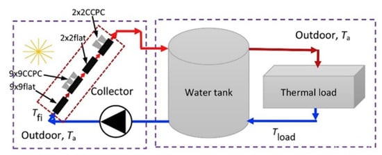
Figure 1.
Schematic of the two-stage hybrid roof-top Concentrator photovoltaics/thermal (CPV/T) system [30].
In CPV systems, increasing concentration ratio monotonically yields higher cell temperature, apart from space heating and residential water, the waste heat at the back of CPV cells can be recovered and injected into various industrial applications. The industrial sector second only to building consumed 37% of the total world energy demand [31]. For reducing the industrial energy consumption, the low to medium grade heat (<150 °C and 150–400 °C) can be provided by solar thermal system. Food, beverages, paper and textiles industries were found to have high demand of heat in low-temperature range. CPV temperature frequently rises above 200 °C as CPVs are mostly installed and operated under immense and stable solar radiation intensity [32]. Due to PCM can store and deliver the thermal energy on demand [33,34], temperatures up to 200 °C can be used to serve various industries by using PCM as the heat storage material. Different PCMs with suitable melting point make it available to store and supply heat demand at desired temperatures for various industrial requirements.
1.3. Methodology and Contribution
This paper focuses on the temperature problem of the CPV system and concentrates on the recent research development during last few years. Thus, the scope of the review is limited by time, and cooling techniques for PV cells or system under concentrated illumination. Based on this scope, the review begins with the analysis of solar energy’s spectral separation to solve the excess temperature problem fundamentally by reducing the amount of thermal energy converted from incident luminous. Then discuss the most important factors of cooling methods when applied to CPV system, and defining the specific cooling requirements. Subsequently, the classification and basic working principles of cooling technologies are introduced. After clarifying the cooling principles, we investigated cooling methods from active and passive aspects and subsequently divided into conventional and advanced techniques. The existing cooling CPV techniques, related modelling or experimental methods, material, influence factors and cooling performance, have been investigated and summarized in tables and figures. Afterwards, we discussed the application condition of different cooling technologies and waste heat recovery, and critically reviewed their advantages and disadvantages as well as economic and environmental impact. Finally, based on the research scenario and research gaps, the challenges, future directions and some recommendations are presented for the research in the CPV cooling field.
There are several existing review papers of cooling technologies for CPV systems, some categorised by CPV system’s geometry and was written before 13 years [35]; some categorised by cooling method’s characteristic and mainly focused on active cooling systems [22]; another reviewed from thermal aspects and preferred the thermal management of concentrated photovoltaics [36]. But compared to various review papers of PV or PV/T system’s cooling technique, the review literature about CPV cooling is very limited. For filling these gaps, this review aims to briefly review the progress in CPV, and define the effective and suitable cooling methods for different CPV systems. The objective is to draw a picture about the concept of CPV systems’ cooling methods that could define the aspects need to be considered in future developments, such as such as electrical performance improvement, hybrid energy output or other purposes. The novelty of this paper lies in:
- An exhaustive review and discussion on the recent development of different CPV cooling technologies (passive and active cooling systems; conventional and advanced cooling systems) are provided;
- It introduces the CPV systems’ applications in different aspects, consists of architectural, commercial and industrial sectors;
- It provides an analysis on spectral separation technology which concerns the excess temperature problem fundamentally;
- It produces a thorough compilation of different CPV cooling techniques combining with the advantages and disadvantages. And the comparative research of CPV cooling is made by the comparison through significant factors like cell temperature, heat transfer coefficient, cooling performance, concentration ratio etc. and summarised in tables;
- Finally, the challenge, research potential and future prospect has been presented.
2. Spectral Separation of Solar Energy
The concentration of a CPV system can achieve tens to hundreds of suns, but only some specific wavelength can be utilised by traditional PV cells to convert into electricity. The spectral response is determined by the selected PV cell’s material. For example, silicon solar cells absorb sunlight with the wavelength of 400–1200 nm, whereas gallium arsenide solar cells can absorb between 400 and 900 nm [37]. The absorbable wavelength takes up only a small part of the entire sunlight spectrum, and the other sun radiation which is out of PV cell’s response wave band, would turn into thermal energy that causes continuous rise of the cell temperature and seriously affects the photoelectric conversion efficiency. Spectral separation of solar energy can address these problems, in which spectral splitting receiver and multi-junction solar cell are the specific applications. Currently, the majority of Concentrator photovoltaics systems use triple junction cells to achieve higher photoelectric conversion efficiency and lower cost. But the triple junction cell has a limited efficiency, and though the spectral beam splitting system can realise high theoretical conversion efficiency it is too costly for mass production [38].
2.1. Multi-Junction Solar Cell
Multi-junction solar cells (MJC) is a typical application of spectral beam splitting technology in the solar energy conversion field, which is caused by monolithically stacking multiple semiconductor materials with different wavelength matching [39]. Because of the characteristics of high reliability, anti-radiation performance and specific power, tandem and multi-junction solar cells are identified to have has the greatest development potential in the future, and are gradually becoming the third generation solar cells and replacing the silicon PV cells in recent years [40].
Multi-junction solar cells demonstrated the highest conversion efficiency of all the photovoltaic technologies. Among the various classes of the multi-junction solar cells, such as Si-base, thin film, space, high-efficiency and concentrator multi-junction solar cells, the concentrator multi-junction solar cell is the type which has been applied in CPV systems. For concentrator multi-junction solar cells, the InGaP/GaAs/Ge triple junction solar cell has been developed from the beginning of 1990. The United States Spectrolab company launched the InGaP/GaAs/Ge triple junction solar cell with the conversion efficiency in single spectrum at 26.8%, 28.3% and 29.9% respectively. Then the company applied the InGaP/GaAs/Ge triple junction solar cell into high concentrated photovoltaic power system, the results shows that the efficiency is up to 41.6%. Besides, GaInP/InGaAs/InGaNAs/Ge four-junction solar cell has been produced by the utilisation of epitaxial growth technology, which expresses the highest conversion efficiency in the world [41].
A novel concentrated photovoltaic-thermoelectric (CPV-TE) system using triple junction solar cell combine with thermoelectric cooler (TEC) and thermoelectric generator (TEG) was invented and experimented by Teffah and Zhang (2017) [42]. The structure of the used triple junction solar cell and the band gap energy of these three junctions are shown in Figure 2. Results showed electrical power generation of the triple junction solar cell would increase by enhancing the concentration ratio, with the increase in the efficiency.
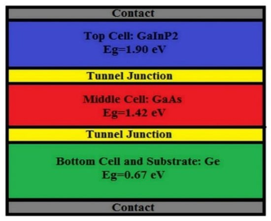
Figure 2.
Structure of triple junction cell based on GaInP2/GaAs/Ge [42].
Sadewasser et al. (2017) [43] conducted the heat management of CuInSe2 micro-concentrator solar cells. The micro-concentrator solar cells showed a significant benefit on heat management over the conventional CPV devices. With the devices are smaller than 200 µm, the temperature increase of micro-concentrator solar cell can be kept to below 10 °C above that of the regular flat panel solar cell. It is concluded that heat distribution can be improved by micro-meter size devices and thus eliminates the needs of any additional cooling systems.
Comprehensive review in the field of spectral beam splitting for photoelectric converting, including the application of multi-junction solar cells, has been presented by many researchers. It is obvious that regardless of the cost and manufacturability, many novel concept designs are proofed to considerably raise the bar for high energy conversion efficiency. Concentrator photovoltaics concept can make the utilisation of spectral separation technology cost-effective.
But there is a lack of the consideration for the spectral separation technology from the economic aspect. As Burhan et al. (2017) [44] indicated, there is no commercial tool available that can analyse CPV performance with the utilisation of multi-junction solar cell, and they proposed and techno-economically analysed a novel standalone CPV-hydrogen system utilizing multi-junction solar cell through a microgenetic algorithm (micro-GA). In addition, whether the reduced power generation costs with the cell efficiency improvement caused by cooling systems can offset or exceed the cooling costs needs to be investigated.
2.2. Spectral Beam Splitting Technology
Spectral beam splitting technology exposes the solar cells to the selected optimum spectrum band, in which the cells express higher performance. This method rejects the light-wavelength which cannot be converted to electricity before it is absorbed by the PV cell. It thus addresses the problem of battery overheating from the source and balances the uneven energy distribution on the surface of PV cell, but requires spectrum matching of the wavelength band and PV cells.
Mojiri et al. (2013) [14] summarised the approaches which can reduce the optical losses, by using a single device to concentrate and split the light into a single stage, the schematic is illustrated as below (Figure 3). The device can be made by a set of prisms based on a curved surface (as Figure 3a shows [45]) or a combination of different dichroic concentrating mirrors, as Figure 3b indicates [46]. The principle is directing the different wavelength bands which are separated by the spectral beam splitter to the most efficient collector. These arrangements make the device realise spectral splitting and produce concentrating effect in the meantime. The advantage is that can reduce the number of interfaces and consequently decrease the reflection losses.
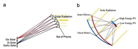
Figure 3.
Device of concentrating and splitting the spectral light into a single stage [14]. (a) A concentrating PV system with spectral separation using a set of prisms; 100× and 17.5× concentration levels for monochromatic and polychromatic (between 730 nm and 1000 nm) beams respectively were achieved [45]; (b) A concentrating PV system comprising a dish shaped 1 m2 reflector made of two layers of faceted mirrors to create two focal points 20 cm off each other; Inner mirror reflects wavelengths above 650 nm and transmits below that; the outer mirror reflects all wavelengths [46].
A novel spectrum splitting CPV system has been invented by Jaker et al. in 2013 [38]. In this system, single and low-cost optical materials with dispersive properties, such glass and plastic, are selected to produce the desired spectral separation. Simultaneously, reverse-ray tracing methods are utilised to optimise the shape of the solar concentrator’s top and bottom interfaces, to ensure that the desired split spectrum would be concentrated to the target PV cells. This novel system has been proved to overcome the efficiency and cost limitations of current spectrum splitting CPV systems, with aggregate cell conversion which exceeds 45%. It shows that the potential of mass production simultaneously meets the requirements for high-efficiency low-cost CPV system.
Similarly, Matthew et al. (2016) [47] retrofitted a standalone parabolic trough plant (PTC) to spectrum-splitting hybrid Concentrator photovoltaics-concentrated PV (CSP-CPV) system. Spectral filtering was adopted to transfer the sunlight which is unusable or poorly utilised for PV to a heat collection element, meanwhile reflect the useful sun rays to a concentrated PV receiver. According to the experimental validation and economic analysis, this hybrid CSP-PV power system expressed the capacity of higher efficiency and lower cost, with 10% output improvement at an expected investment cost of less than $1 per additional net Watt, when compared to existing PTC plants. Meanwhile, it preserved the dispatchability of the CSP system’s thermal energy storage.
Widyolar et al. (2018) [48] firstly simulated and optimized the hybrid solar CPV/CSP parabolic trough collector (PTC) systems (single stage and novel two stage design) with spectral and temperature optimization, which integrated with different spectral beam splitting (SBS) approaches (ideal, interference filter, and novel integrated semi-transparent/back-reflecting solar cell filters) with different solar cells (c-Si, CdTe, GaAs, InGaP), to maximise the solar-to-electric conversion. According to Yaping et al. (2015) [49] and Widyolar et al. (2017) [50], out-of-band transmission in a semi-transparent triple junction cell could be 87% (ignoring grid contact shading losses) [49], and out-of-band reflectance of a bare GaAs cell was reported to be 92% (closer to 83% with assumed encapsulent losses) [50]. Because typical c-Si and CdTe cells present high absorption for post-bandgap wavelengths that cannot be used as spectrum splitting devices [51], Widyolar et al. (2018) [48] novelly utilized semi-transparent or back-reflecting solar cells (GaAs, InGaP) as the beam splitters for a two-stage CPV/CSP parabolic trough collector (PTC) system, the schematic is shown in Figure 4.
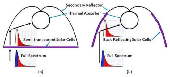
Figure 4.
Spectral beam splitting by solar cells (purple) in semi-transparent (a) and back-reflecting (b) configurations as part of a secondary concentrator. High energy photons are absorbed and low energy photons are either (a) transmitted into the secondary concentrator or (b) reflected towards the thermal absorber [48].
Results showed all cases show improvement and spectral beam splitting enhances solar-to-electric conversion 45% over traditional PTC CSP system. The hybrid CPV/CSP system thermally-generated electricity at a lower cost than current CSP by efficiently utilising the solar spectrum, and economic assessment pointed the installation cost of c-Si SBS PTC system using interference filters is $2.39/W. But the novel semi-transparent and back-reflecting solar cell beam splitters demonstrated lower conversion efficiencies than typical interference (dichroic) filter systems [48].
Table 1 summarised all the mentioned spectral separation techniques of solar energy above:

Table 1.
Summary of spectral separation techniques of solar energy.
3. Analysis on Design Considerations of Cooling Methods for CPV Systems
According to existing literature, the design considerations of cooling systems for CPVs are mainly divided into four aspects: temperature of solar battery, temperature uniformity, practicability and reliability of the cooling system, as well as economic and environmental impact.
3.1. Temperature of Solar Battery
Generally, the PV cell’s operation temperature, maximum temperature and temperature degradation coefficient would be provided by manufacturers. The heat dissipation system should decrease the cell temperature to the greatest extent with the satisfaction of the temperature limit, also need to balance the cooling cost. Temperature decrease has been proved can enhance the solar-to-electricity conversion efficiency, extend the solar cells’ service life and further reduce the cost of the CPV system.
3.2. Temperature Uniformity
The conversion efficiency is affected by the temperature uniformity of the solar cell to some extent. According to research, traditional solar concentrators including dish concentrators, parabolic trough concentrators (PTCs) and compound parabolic concentrators (CPCs) usually cannot produce a uniform concentration on the absorber’s surface [52]. Thus, “high-flux hot spot” usually occurs on the on the CPV module with the non-uniform concentration. These “hot spot” regions have a heat flux several times higher than the module average that causing exceedingly high temperatures and hence dramatically degrade the system performance and reliability [53,54]. Baig et al. (2012) [55] pointed out the uneven concentration of concentrating solar cells increases the cell temperature, cell resistance and causes power loss. As Figure 5 shows, an ideal solar cell would undergo a series of losses when placed under a CPV system, in which either the effect of non-uniform illumination or cell temperature on efficiency loss is obvious.
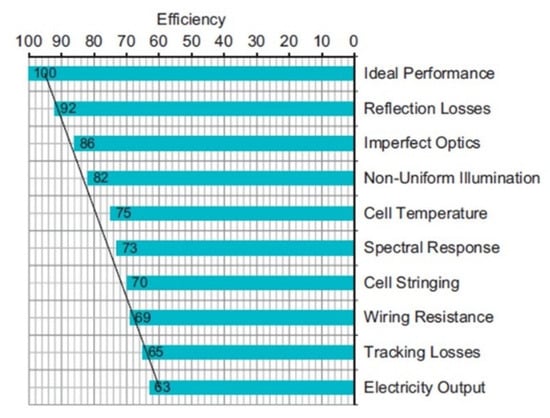
Figure 5.
Losses occurring in the CPV system [55].
Solar cells are usually paralleled after connected in series to enhance the power generation efficiency. As current is equal in the series circuit, in the case of certain output power, increase in the output voltage and decrease in the output current of the serial battery can minimize the energy loss from the cell resistance. Thus the output power of the entire assembled battery will be limited by the battery which has the highest resistance, and the cell that exhibits the highest cell temperature and the lowest efficiency will, therefore, limit the efficiency of the entire photovoltaic system. There are two common approaches to solve this problem. The first is adding bypass diodes to automatically cut-off the least efficient battery power output when the cell temperature achieved a certain value [56]. The second is adopting a heat-removal system to ensure the temperature uniformity of the battery pack. Under this circumstance, the thermal management system is necessary to be coupled with the CPV system for its proper functioning. Also, it should satisfy the excellent heat dissipation performance without making the temperature deviation worse.
3.3. Practicability and Reliability of the Cooling System
The thermal dissipation system is ultimately designed to improve the cell performance and reduce the generating cost. The initial investment, maintenance cost, energy consumption, material and simple construction, etc. factors should be taken into account for the practicability of the cooling system. As the power required of any active component of the cooling device is a parasitic loss for CPV system [57], it is necessary to guarantee that the cooling system’s energy consumption is lower than the CPV system’s efficiency improvement. The reliability of the heat removal system determines the efficiency, maintenance cost and service life of the solar cell. Thus extreme conditions, such as maximum temperature limit and system failure, should be considered when designing, while the weight also needs to be considered.
3.4. Economic and Environmental Impact
Environmental problems and cost-effectiveness are two crucial issues that can be faced with during the installation of the solar power systems [58]. For a solar power system, the major economic benefits arise from waste heat utilisation and cost savings during operations [59]. From an economic perspective, the cooling device increases the CPV system’s reliability and reduces the cost. Combined heat and power generation technology (also called cogeneration) make the waste heat can be used for other purposes. Combining the solar power system with other equipment can significantly reduce operating costs and environmental pollution [59].
However, as Bahaidarah et al. [60] pointed out that, based on the existing research, there is an absence of studies for analysing the CPV cooling systems from the economics and environmental aspects. Little research was founded in this area while the majority of research were only conducted from the technical direction.
4. Cooling Technologies of CPV Systems
4.1. Classification and Basic Working Principles
Cooling technologies of CPV system can be divided into two types: passive cooling and active cooling. Passive cooling system has the advantages of zero energy consumption, low cost and easy installation. Back metal plate of high conductivity material with or without fins and heat pipe cooling system are the representative models. According to previous works, metal plates were usually utilised as the heat sink for passive cooling the photovoltaic module [61,62,63]. Cheknane et al. (2006) [64] proposed a heat sink integrated with a heat pipe for cooling CPV cells. The passive cooling system has mainly been applied in low concentration ratio due to its limited cooling effect. Earlier studies of Royne et al. (2005) [35] on cooling methods of CPV system pointed that the passive cooling was insufficient for linear concentrator when CR above 20 suns.
Royne et al. (2005) [35] indicated active cooling system also uses thermally conductive heat sink to strengthen the heat transfer efficiency but the difference is the active system uses forced circulation, thus the additional electricity consumption is unavoidable. The active CPV cooling systems were proved can overcome the passive cooling system’s existing challenges and shows greater competitiveness on higher CR (above 100) [65]. Its characteristics of high heat dissipating capacity make it commonly adopted in high concentrated PV power generation system [65].
For the traditional cooling systems the working mediums usually are water or air. Table 2 compares air and water’s Convective Heat Transfer Coefficient (CHTC) under natural and forced convection situations. It is obvious that the Convective Heat Transfer Coefficient (CHTC) of active cooling systems is much higher than that of passive cooling systems and water is a better cooling medium compared to air. Thus, air is usually used in some low concentrating systems to alleviate the temperature [66].

Table 2.
Convective Heat Transfer Coefficient of Air and Water under natural and forced convection.
Air cooling either by forced or natural flow provides a low-cost and simple heat-dissipating way, but air’s poor thermo-physical characteristic offers a relatively low cooling efficiency [66,67]. The heat exchange performance of air cooling is related to the air flow rate, flow length and height etc. Higher heat transfer effect could be achieved by optimising these parameters. Brinkworth and Sandberg (2006) [68] indicated that for a certain length of a PV array, the best cooling performance would be achieved when the ratio of the PV array’s length (L) to the air flow’s hydraulic diameter (D) is 20 (L/D = 20), without consideration of the influence of other factors. This helps to choose the power rating of blower to avoid unnecessary energy waste.
Water cooling technology also can be divided into two types, natural and forced circulation cooling. The crucial factor of is to ensure the good heat conduction and keep the electric insulation between the PV cell and the surface of heat exchanger. The leakage problem of the working medium should also be taken into consideration. A typical water cooling system is composed by a heat exchanger, a water tank, valves etc. The basic schematic of is shown in Figure 6.
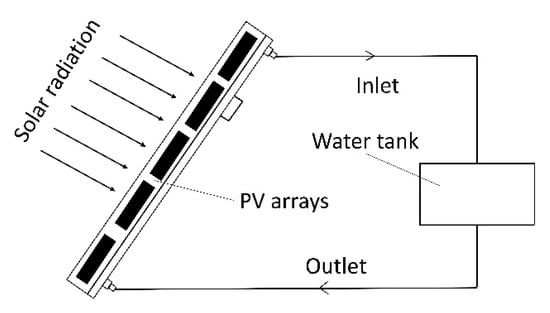
Figure 6.
Schematic of Water Cooling Technique.
4.2. General Comparison of Different Cooling Techniques for CPV System
The CPV cooling technologies are categorized into active and passive cooling. With the developing investigation of cooling technologies, besides the conventional air and water cooling methods, some advanced cooling technologies, such as microchannel cooling, impinging jet cooling, liquid immersion cooling, heat pipe cooling, phase change material, promising ground-coupled cooling as well as earth water heat exchanger cooling, are applied and assessed for cooling the CPV system. The advantages, disadvantages and applications of above various cooling technologies are discussed and represented in a tabular form. Combining the information of Jakhar et al. (2016) [22], Table 3 gives a comparative study of different cooling techniques for CPV system. This paper also introduces the impaction of spectral separation and cogeneration technology on CPV system. More on these different cooling technologies are later illustrated in the article.

Table 3.
Comparative study of different cooling techniques for CPV system.
5. Passive Cooling for CPV Systems
5.1. Air Cooling
Kraus and Bar-Cohen (1995) [69] demonstrated many earlier studies focused on natural convective heat transfer from heat sinks consisting of plate-fins. Araki, Uozumi and Yamaguchi [70] investigated the natural convection cooling performance of single PV cell under the concentration of 500 suns in 2002. The results demonstrated that the good thermal contact between batteries and aluminum plate is critical for the cell temperature decrease. Mittelman et al. (2007) [71] pointed the downward facing fin array has been neglected in the past as it is not the preferred orientation for effective natural convection. But the exploration of this heat sink has begun recently because they are specifically preferred by modern telecommunication equipment and CPV system.
Aldossary et al. (2016) [72] conducted a thermal simulation of a single CPV system to investigate the performance of the passive air-cooled device under high solar concentration (500 suns) in a harsh environment (like Saudi Arabia where the ambient temperature can reach up to 50 °C in summertime). Two types of heat sink, Round Pin Heat Sink (RPHS) and Straight Fins Heat Sink (SFHS), attached to a 3 × 3 mm size single triple junction III-V PV cell, the schematic are shown in Figure 7. The simulation revealed that although the PV temperature dropped dramatically after integrated with RPHS and SFHS heat sink (from about 922 °C to less than 117 °C, and to less than 96 °C respectively), both of these heat sinks are insufficient to maintain the required PV surface temperature and electrical efficiency especially under high ambient temperature. SFHS showed better performance than RPHS with surface temperature of 21 °C lower under the same situation. This proved that the design of the heat sink has significant impact on the heat dissipation performance.
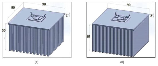
Figure 7.
Round pins heat sink (a) and Straight fins heat sink (b) [72].
Micro-fins have been identified as one of the most promising CPV cooling technology while there is still a lack of research about it. Micheli et al. (2016) [73], through the thermal modelling identified the most convenient fin geometry for CPV systems with 500 suns. A single CPV cell integrated micro-fins heat sink was tested under Concentrator Standard Test Conditions (CSTCs) and Worst Case Conditions (WCCs) with the heat transfer coefficients of 2.44 W/m2·K and 2.85 W/m2·K respectively. Results showed micro-fins improved the thermal performance and also reduced the weight of cooling system. Maximum cell’s temperatures of 73 °C and 103 °C are predicted under CSTCs and WCCs respectively. Under natural convection, the optimized fin array with the maximised fin effectiveness, causes maximum mass-specific heat transfer and leads to 50% increase in mass-specific power compared to an unfinned surface. This mass-specific power is six times higher than that calculated for standard CPV heat sinks. Figure 8 and Figure 9 introduce the geometry of micro-fin.

Figure 8.
Cross-sectional view of the micro-finned silicon wafer and zoom on the fins [73].

Figure 9.
The geometries of (a) unfinned silicon wafer; (b) micro-finned silicon wafer [73].
Research in the last few years [29,74,75] indicated the Crossed Compound Parabolic Concentrators (CCPCs) present good optical performance and lower cost than traditional Compound Parabolic Concentrators (CPCs). When integrated with PV module, air-filled CCPCs designed with high natural convective heat transfer coefficient can discharge the heat efficiently to the ambient air and maintain a low cell temperature. However, natural convective heat transfer in CCPC enclosures has attracted very little attention compared to CPCs so far [76]. For example, Mammo et al. (2013) [75] combined CCPC with PV cell, measured the optical, electric performance and temperature on the bottom cover, but ignored the natural convective heat transfer in the CCPC cavity.
Li et al. (2017) [76] numerical simulated and experimentally studied the natural convective heat transfer phenomenon in an isolated, walled CCPC integrated with PV. The irradiance was 1000 W/m2 with 28.5 °C ambient temperature and various incidences of 0°, 10°, 20°, 30° and 40°. The experimental setup is shown in detail as Figure 10. Results identified that the optical and heat transfer performances of CCPC were dependent on the incidence, as the PV cell was subject to the highest temperature with the incidences less than 20°.
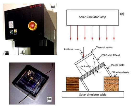
Figure 10.
WXS-210S-20 solar simulator (a), a picture of the Crossed Compound Parabolic Concentrators (CCPC) with PV cell (b) and a position of the CCPC in experiment (c) [76].
5.2. Liquid Immersion Cooling
Han et al. (2013) [77] developed and tested a CPV integrated with direct liquid-immersion cooling system, as Figure 11 shows. The long-term stability and performance of silicon PV cells (100 × 100 mm) were researched through four separate liquid immersion experiments respectively: ethyl acetate, dimethyl silicon oil, isopropyl alcohol (IPA) and De-ionized (DI) water. The experiments were under the concentration of 10 suns, 20 suns and 30 suns, and the results showed higher power output could be achieved with higher concentration ratios. The cell efficiency had increased by 8.5–15.2% with a 1.5 mm liquid film. But it was difficult for PV cell to maintain stable electrical performance when immersed in 9 mm liquid layer of deionized water, because more incident light was absorbed with the increase of thicker liquid layer. Besides, the interaction between the silicone sealant and IPA or ethyl acetate resulted performance decay of the silicon CPV solar in 1.5 mm test.
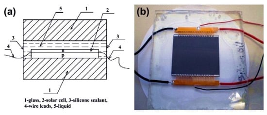
Figure 11.
(a) Schematic cross-section of mini-module; (b) one mini-module with silicon CPV solar cell (3 immersed in dimethyl silicon oil designed for 1.5 mm test) [77].
Xin et al. (2015) proposed an electrical characteristics investigation of a GaInP/GaInAs/Ge triple-junction PV cell (1 × 1 cm2) immersed in dimethyl silicon oil at 500 suns [78]. The silicon oil thickness varies from 1.0 to 30.0 mm, experimental results showed cell electrical performances reduced with the increase of oil thickness. The maximum increase of the output power and conversion efficiency were achieved with the solar cell immersed in 1.0 mm thickness, from 39.567% and 19.556 W to 40.572% and 20.083 W respectively. The cell efficiency and output power were less than those without liquid-immersion when the oil thickness exceeds 6.3 mm. However, according to CFD simulation (shown in Figure 12) the oil thickness should not less than 2.5 mm and mass flow rate no less than 20 kg/h to maintain the low and uniform cell temperature.
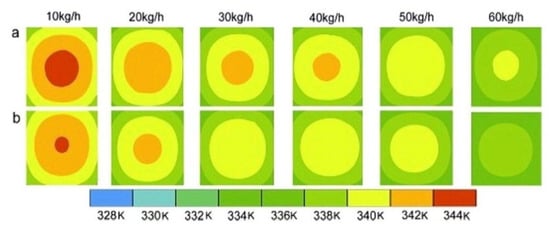
Figure 12.
Temperature distribution of concentrator triple-junction PV cell immersed in the 2.5 mm silicon oil thickness with different mass flow rates: (a,b) represents the front surface and the rear surface respectively [78].
A novel direct-contact phase-change liquid immersion cooling method for high concentrating photovoltaic (HCPV) system was conducted by Kang et al. (2016) [79]. In this study, ethanol was used as the phase change immersion cooling liquid. This cooling system can modulate automatically and run self-propelled steadily without consuming extra energy under the concentration ratio ranged between 219.8 and 398.4 suns. Experimental studies showed the temperature was well controlled in the range between 87.3°C and 88.5°C, and the PV cell’s surface heat transfer coefficient was up to 46.98 kW/m2·K under 398.4 suns. The dominant factor for the decline of electrical performance is the light loss at the interface between bubble and ethanol (shown in Figure 13), that Isc and Pmax decreased 10.2% and 7.3% respectively of triple-junction PV cells.
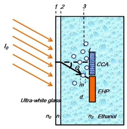
Figure 13.
The model of bubble effect on light (CCA: Concentrator Cell Assembly; EHP: Electric Heating Plate) [79].
5.3. Heat Pipe Cooling
Heat pipe has the characteristics of high heat transfer and high thermal conductivity ability makes it a good alternative to large heat sink, especially due to limited space [80]. Anderson et al. (2008) [81] designed, fabricated and tested a copper heat pipe integrated with aluminum fins for cooling a CPV system by natural convection at 30 suns, of which toluene, ammonia, pentane, methanol and water were the working fluids. The CFD software was used to decide the optimum spacings and fin sizes. Water was found as the best working medium compared to others. The heat pipe rejected the heat by natural convection with a total cell-to-ambient temperature rise of only 40 °C under a cell level waste heat flux of 40 W/cm2, while the single aluminum plate would have a ∆T of 110 °C.
A fabrication method of a novel hybrid-structure flat plate (NHSP) heat pipe was designed and investigated by Hsin-Jung et al. (2012) [82] for cooling CPV system. This NHSP heat pipe contained a flattened copper pipe and a sintered wick structure which was supported by a coronary-stent-like rhombic copper mesh. Experiments demonstrated the sintered capillary heat pipe can realise a thermal resistance reduction of approximately 72% compared to traditional copper mesh-screen heat pipe. The thermal resistance also can be decreased by 65% by adding the supporting structure. Thus, the NHSP heat pipe displayed the best performance that increased the conversion efficiency of CPV system by approximately 3.1% in a single PV cell compared to an aluminum substrate.
Dong et al. (2014) [32] proposed a CPV cooling system integrated an insulated aluminium thermal absorber with two heat pipes by. A 10 × 10 mm2 size InGaP, InGaAs and Ge triple-junction solar cell was placed on the thermal absorber while distilled water is the working fluid in the heat pipe. The experiments showed the PV temperature was 29.3 °C, 33.3 °C, 37.2 °C and 41.2 °C under the concentration ratio of 500 suns, 600 suns, 700 suns and 800 suns respectively. And the electrical and thermal efficiency of CPV system is 20% and 77% respectively.
5.4. Phase Change Material
Phase Change Material (PCM) can keep a relatively stable temperature during the heat absorption process, hence attracted an ever-increasing attention in thermal management [83]. Sharma et al. (2016) [84] firstly experimentally evaluated PCM via thermal regulation to enhance the performance of low-concentration Building-Integrated Concentrated Photovoltaic (BICPV) system. This work proposed and implemented a new analytical model for the in-house controlled experiments. Results showed that PCM effectiveness increase with the increase of irradiance. In comparison with naturally ventilated system, a rise in relative electrical efficiency by 7.7% and an average decline in module centre temperature by 3.8 °C were observed of BICPV-PCM integrated system under highly collimated continuous light source at 1000 W/m2.
Emam et al. (2017) [85] numerically simulated the performance of an inclined concentrated photovoltaic-phase change material (CPV-PCM) system, the schematic is shown in Figure 14. The CPV was integrated with phase change material with thickness of 50 and 200 mm, the inclination angle of CPV-PCM system was be settled in the range of −45° to 90° in an interval of 45°. With the concentration ratio of 5 and 20 suns, the results indicated that the inclination angle has a significant effect on the time of PCM required to reach the complete melting state, transient average PV cell temperature and temperature uniformity. With the inclination angle varies from 0° to 90° a remarkable decrease of the average PV cell temperature with enhanced uniformity is achieved, the most uniform temperature is observed at 90° with a reasonably low average temperature. The minimum average temperature and highest solar cell electrical efficiency can be obtained with reasonable uniformity at 45° for the whole time period until PCM’s complete melting, whereas the solar cell electrical efficiency is dramatically reduced with time at −45° (5% at −45° while 17% at 45°). Also the highest average cell temperature with the worst temperature uniformity is obtained when inclination angle is −45°. These results help to prevent the hot spots in the solar cell.
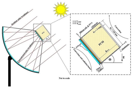
Figure 14.
Schematic of CPV-Phase Change Material (PCM) system [85].
A smallscale concentrating photovoltaic-thermal (CPV-T) system with PCM cooling was built by Su et al. (2018) [86] to on-site experimental measure the effects of using PCM cooling. Experiments demonstrated the effective enhancement could be improved by PCM cooling system, with the range of output power from solar irradiance more than 300 W/m2 to more than 50 W/m2. The present CPV-T system with PCM enhanced the electrical, thermal, and overall energy efficiencies by 10%, 5%, and 15% respectively, compared to the previous CPV-T system with water cooling.
Table 4 lists the summary of all the Passive Cooling Technologies mentioned above.

Table 4.
Summary of the Passive Cooling Technologies.
6. Active Cooling for CPV Technology
6.1. Conventional Cooling Technologies
6.1.1. Air Cooling
Amri and Mallick (2013) developed a heat transfer model [87] to predict the triple-junction GalnP/GaAs/Ge cell temperature under 100, 150 and 200 suns. A forced air cooling system with 1.5 mm thick aluminium plate was adopted in this experiment. Figure 15 is the schematic of the system. The results showed that this active air cooling system can adequately cool the PV cell under medium concentration ratios with maximum 50% temperature decrease. However, the 1.5 mm thick is less effective for high concentration ratios and the channel width needs to narrow to micro-meter value in order to achieve the required cooling efficiency. For example, the solar cell can be adequately cooled up to the concentration ratio of 200 and 345, when the channel width is narrowed to 1 mm and 0.5 mm respectively. Overall, the conjugation effect, air inlet velocity and channel width were found to have noticeable effects on PV temperature.
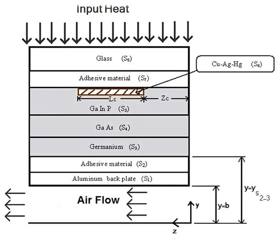
Figure 15.
Schematic of the multi-junction CPV system integrated with active cooling device [87].
One year later, Amri and Mallick (2014) [88] developed a numerical heat transfer model of a triple-junction CPV system coupled with a forced air cooling device, to investigate the cell temperature and thermal characteristics of the airflow under nonuniform incident illumination. The Schematic diagram is shown in Figure 16. It indicated that the nonuniform illumination caused hot spots in some regions on the surface of the solar cell, resulting in a drastic reduction in overall efficiency. At medium concentrations (100 suns), though the maximum PV temperature can be reduced by as much as 35% and 20% respectively with the increasing emissivity of the two duct walls and increasing Re, cell temperatures exposed to the region of the most incident light are overheated and caused degradation in solar cell efficiency. According to the results, a conventional plain channel cooling system was inefficient for cooling the PV cell under medium concentrations with the non-uniform light distribution. Thus, an innovative cooling system, such as introducing a secondary jet flow into the channel, could redistribute cell temperatures and reduce it to an acceptable value.
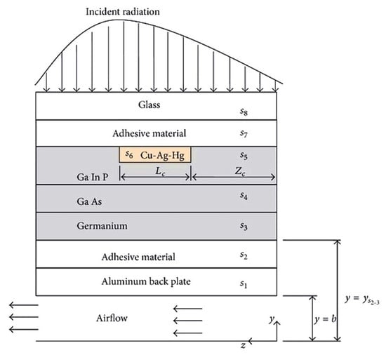
Figure 16.
Schematic of the triple-junction CPV system integrated with forced air cooling device [88].
Wang et al. (2017) experimental and numerical studied the passive and active cooling techniques for a novel CPV/CSP hybrid solar system [89]. The schematic of two cooling design options are illustrated in Figure 17. Heat pipes with annular fins presented better performances than with radial fins under the same conditions. But both of these two passive cooling methods can only handle the heat load below 50 W. In contrast, the active cooling method can maintain the average PV cell temperature below the target temperature of 75 °C even under 45 °C ambient with less than 2 W fan power consumption. From the aspect of temperature control results and system cost, active cooling design was selected for to dissipate a maximum waste heat of 84 W (21.8 W/cm2) because its capability of lower cost, lower PV temperature, and higher net energy efficiency gain. The passive cooling would become more attractive with the heat dissipation requirement of less than 50 W (13.0 W/cm2).
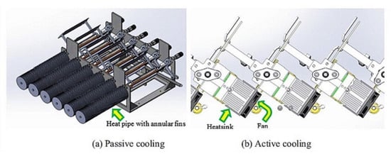
Figure 17.
Schematic of two cooling design options: (a) passive heat pipe cooling; (b) active fan cooling [89].
6.1.2. Water Cooling
Du et al. (2012) developed and actual tested a CPV with aluminum water-cooler [90]. Operating temperature, power output and efficiency were tested to investigate the PV module’s performance. The operational temperature was reduced under 60 °C, therefore, increased the efficiency of the CPV and produced the more electric power output. The cooling water flow rate was found that significantly affect the heat extraction rate and hence help manage the cell temperature. As Figure 18 shows, the electrical efficiency and the thermal efficiency increases rapidly with the raise of cooling water flow rate. Both the electrical and thermal efficiency has become almost constant when the flow rate above 0.03 kg/s. It was because the heat extracted by the cooling water reached a relatively saturated level at 0.03 kg/s.
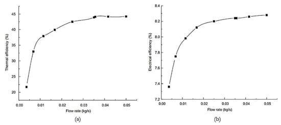
Figure 18.
Effect of water flow rate on thermal efficiency (a) and electrical efficiency (b) [90].
Sabry (2016) [91] presented a Computational Fluid Dynamics simulation of highly concentrated active water-cooled solar cells to investigate the effect of CHTC, water flow rate and tube internal diameter on PV temperature under 100, 200, 300 and 500 suns. Results showed that increasing CHTC significantly reduced PV temperatures at low flow rates with high concentration ratios, especially with increasing the number of PV cells connected to the tube, while increasing flow rates decreased the effect of CHTC on cell temperature. According to the Figure results, widening the internal diameter reduced cells temperatures at higher optical concentration ratios and at low flow rates.
Chaabane, Mhiri and Bournot (2016) [92] presented a 3D computational fluid dynamics model to predict the thermal and electrical performance of a water-cooled CPV system. To avoid the hot spots on the cell module, a rectangular channel was finally employed after increasing the number of cooling water pipes. The final optimum design presented a solar cell temperature of 315.15 K and a thermal and combined (thermal plus electrical) efficiency of 74.2% and 83.5% respectively. The results showed the number of pipes and water flow rate significantly affects the thermal electrical efficiency.
Aldossary et al. (2016) [72] simulated the active water cooling device of a single CPV system. Results proved 0.01 m/s water active cooling can maintain the solar cell surface temperature at around 60 °C and electrical efficiency at 39.5% under 500 suns, regardless of the ambient temperature. Active water cooling can be more cost-effective with the carried thermal energy being in thermal applications. It was found that when 14 single CPVs were placed above the cooling channel the outlet water average temperature rose to 90 °C, which made it possible for coupling a single stage absorption heat pump for cooling. Figure 19 shows the PV temperature profile for active cooling case when ambient temperature is 16.9 °C and water inlet temperature of 15.7 °C.
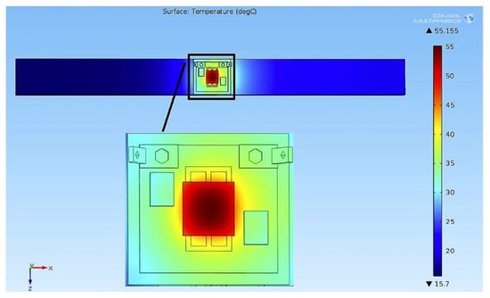
Figure 19.
PV temperature profile for active cooling case at 16.9 °C ambient temperature and water inlet temperature of 15.7 °C [72].
6.2. Ground-Coupled Central Panel Cooling System
The ground has been used as a heat sink for cooling for a long time, while it is indeed a brand-new perspective in the realm of the cooling of PV panels. Sahaya et al. (2013) [93] designed and optimised an innovative Ground-Coupled Central Panel Cooling System (GC-CPCS) for cooling Solar PV panels, of which air is the cooling medium. The arrangement is shown in Figure 20a and the schematic design is shown in Figure 20b. The air would be cooled by passing through the ground-coupled heat exchanger, and then driven by a blower to each solar panel through distributed pipes. In this layout the blower was run by power provided by a separate and dedicated PV cell that consumed 5% of the total power output. The new system proved to require less pumping power and provided low capital cost per watt output.
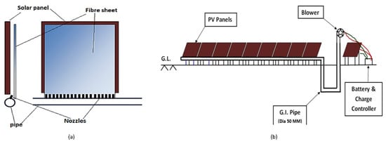
Figure 20.
Arrangement of solar panel, fibre sheet and nozzles (a) and schematic design of Ground-Coupled Central Panel Cooling System (GC-CPCS) (b) [93].
Sahaya et al. (2015) [94] then installed and actual tested the GC-CPCS system by using Smoke Flow Visualization technique to simulate the flow of air. Copper nozzle with 4 mm internal diameter was used in the test. Smoke was found uniformly distributed to all PV panels. With the optimized GC-CPCS cooling system, the efficiency of PV panel increased from 23.11% to 25.29% with PV temperature of 35 °C. However, because of the low thermal transfer and carrying capacity of air, large surface area and high electrical consumption were required for heat dissipation. Thus, more effective cooling performance and hence better conversion efficiency can be achieved by working fluid with high heat transfer capacity. It was unique to introduce the concept of Central cooling of PV panels. Also, it was the first time for Ground-coupled Heat Exchanger to be used in Solar PV Panel Cooling System.
6.3. Earth Water Heat Exchanger Cooling
Similarly to Ground-coupled Central Panel Cooling System mentioned before, the EWHE is also new in the field of the cooling of CPV system. A novel earth water heat exchanger (EWHE) has been designed and simulated by Jakhar et al. (2016) [95] for concentrated photovoltaic cooling under the local conditions of Pilani, Rajasthan (India). Parametric study of EWHE was conducted through changing the value of operating parameters, including mass flow rate, pipe diameter, pipe length, pipe material and burial depth. The soil temperature has been evaluated and indicated that the depth of 3.5 m is sufficient for pipe burial. The EWHE performance was found increased with the increase of pipe length, and decreased with the increase of mass flow rate. With the rising pipe diameter, the system performance increased but the economic factor also increased at the same time. According to the comparative study between three different materials, materials had lesser impact on the EWHE performance which means the cheapest High-Density Polyethylene pipe can be used. Then the simulated system was compared with existing cooling systems of CPV in the literature, estimated the effect of replaced the same by EWHE. Under the same condition of the referenced CPV setup in the literature, the temperature drop from 48.5 °C to 25.5 °C could be achieved by the EWHE system pipe with the length of 60 m. Results showed that the EWHE system gives better performance than the reference cooling system. It was concluded that coupled EWHE with CPV plants could realise economical and performance enhancer.
Jakhar et al. (2017) [96] then modelled and simulated the EWHE system based on the transient thermal analysis for ten hour operation during peak summer day (21 June). The variation in concentration ratio and mass flow rate has been investigated to estimate the CPV cell temperature and power output. Simulation showed the maximum CPV temperature reached 416.36 °C at 3 suns without any cooling, whereas the temperature reduced drastically to 85.28 °C with the mass flow rate of 0.022 kg/s after integrating the EWHE cooling. The CPV power gradually and temperature drop increases with mass flow rate increases, and the mass flow rate of 0.022 kg/s had been proved to be the optimum flow rate that may be used for the practical applications.
Jakhar et al. (2017) [97] also utilised the EWHE to cooled a new hybrid photovoltaic thermal solar (IPVTS) system. Experimental and theoretical analysis was conducted to investigate the electrical and thermal performance of IPVTS system coupled with EWHE cooling. The study indicated that the experimental electrical efficiency of the coupled IPVTS system increased 1.02–1.41% compared to which without EWHE cooling. The maximum PV temperature decreased drastically from 74.5 °C (without any cooling) to the range between 39.27 °C and 46.11 °C (with EWHE cooling) at the flow rate of 0.033 kg/s, and 0.033 kg/s was experimental proved as the optimum flow rate.
6.4. Microchannel Cooling
Research indicated that microchannel cooling technique can provide the utmost possible reduction of PV cell temperature compared to other cooling technologies [98]. A novel CPV cooling system using multi-layer manifold microchannel system was developed by Yang and Zuo (2015) [99] for improving the uniformity of surface temperature distribution. Figure 21 shows the schematic diagram of the multi-layer manifold microchannel testing unit, three common silicon solar cells were connected in series during the experiment. The results showed the CPV cell temperature reduced from 44.1 °C to 20.4 °C with the flow rate of 0.00535 kg/s to 0.0232 kg/s and would not change beyond the flow rate of 0.0232 kg/s under 28 suns. And performance slightly declined with water flow rate increased due to Ppump rise. This cooling system presented a heat transfer coefficient of 8235.84 W/m2·K with a pressure drop less than 3 kPa. Besides, it proposed a small surface temperature difference (less than 6.3 °C) of the CPV cells.
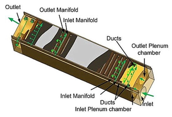
Figure 21.
Schematic diagram of the multi-layer manifold microchannel testing unit [99].
Radwan et al. (2016) [100] developed a new microchannel heat sink with nanofluids to cool the low concentrated photovoltaic-thermal (LCPV/T) systems, in which Al2O3-water and SiC-water were cooling mediums. The system was analysed under 10, 20 and 40 suns. Major temperature reduction of the PV cell was observed with the increase of nanoparticles’ volume fraction, and SiC-water nanofluid achieved a relatively higher decline in cell temperature than Al2O3-water nanofluid. The studies proved that LCPV/T system can realise better performance by using nanofluids than water with the cell temperature reduced to 38 °C and the electrical efficiency increased to 19%, especially at high solar concentration ratios.
Similarly, the performance of the LCPV/T system incorporated with a microchannel heat sink was investigated by a comprehensive thermal model at different operating conditions according to Radwan et al. (2016) [98], the schematic sketch is shown in Figure 22. It also has been proved that microchannel heat sink has strong abilities in solar cell temperature reduction and uniform temperature distribution. With the microchannel flow Reynolds number of 100, the CPV cell temperature varied between 33.5 and 35.6 °C at a concentration ratio of 20 suns, while at 40 suns it ranged from 37 and 41 °C. In addition, the electrical efficiency reached 18.5% with the thermal efficiency achieved the maximum of 62.5%, while the microchannel friction’s power loss was estimated to be about 0.4% of the electrical power output. For all values of concentration ratios, the performance of the LCPV/T system was significantly enhanced by the increase of cooling fluid Reynolds number, which was presented as higher electrical and thermal efficiency, and lower cell temperature.
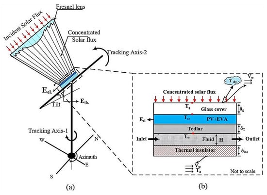
Figure 22.
A neat schematic sketch of the proposed physical domain (a) and components of CPV/T system (b) [98].
6.5. Jet Impingement Cooling
Jet impingement cooling can realise very low thermal resistances, generally is 105–106 Km2/W [101]. Its potential of achieving high heat transfer rates makes it becoming an attractive cooling method. A jet impingement cooling device was designed by Royne and Dey (2007) [102] for cooling densely packed PV cells under high concentration. They developed a model to predict the pumping power of different shape devices. The studies showed that the performance improved by increasing the nozzle number per unit area. Besides, Huber and Martin models were adopted for different concentration level. PV cell temperature reduced from 60 °C to 30 °C at 200 suns and from 110 °C to 40 °C at 500 suns in both models.
Barrau et al. (2011) [103] studied the performance of a novel hybrid jet impingement/micro-channel cooling device for densely packed PV cells under high concentration. It combined a slot jet impingement with non-uniform distributed micro-channels. Research showed the optimum Reynolds number of the coolant flow, for which the highest net PV output of the concentrator PV was obtained, up to the concentration level. The principle and operation is illustrated in Figure 23. The increase of the power produced by the concentrator PV would lower than the increase of the pumping power of the cooling system, when the Reynolds number higher than the optimum value. A minimum thermal resistance coefficient of 2.18 × 10⁻⁵ Km2/W was realised by this hybrid cooling device with the pressure drop lower than which of micro-channel systems. This characteristic caused net PV output when cooled by this hybrid device would be higher than which cooled by the micro-channel. Furthermore, the hybrid system can modify the internal geometry during the design stage to adapt the distribution of the heat removal capacity, that to improve the temperature uniformity. Whereas the micro-channel design can only reduce the PV temperature by increasing the flow rate of coolant.
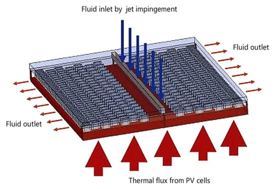
Figure 23.
Principle and operation of the hybrid cooling device [103].
In 2014, the hybrid jet impingement/micro-channel cooling device mentioned above was outdoor tested by Barrau et al. [104]. A dummy cell made by brass (size 29.75 mm × 29.75 mm with 2 mm thickness) was used instead of using a real solar cell for testing. The schematics are shown as Figure 24. According to the results, uniform temperature at flow rate of 0.049 kg/s was obtained under both concentration ratio of 373 and 537, and achieved low thermal resistance (about 6.2 × 10⁻⁵ Km2/W) with the same flow rate. Thus proved the thermal resistance coefficient and the temperature uniformity offered by this cooling system can meet the requirements of CPV receivers. The net PV output increased with the PV cell efficiency and concentration ratio (at 298.15 K), in the range of flow rates considered in this work. And they correlated the flow rate and concentration ratio as a function of temperature.
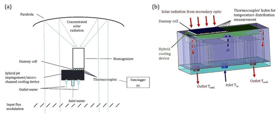
Figure 24.
Schematic of the concentration system (a) and cooling device (b) [104].
Table 5 lists the summary of the Active Cooling Technologies mentioned above.

Table 5.
Summary of the Active Cooling Technologies.
7. Cogeneration Power Technology
Cooling devices can resolve the issue of overheating, but the lower quality heat (about 50 to 60 °C) produced by the cooling process is the waste heat for the solar power system. Nevertheless, higher thermal energy produces higher heat load that results in higher performance requirement of the cooling system. As it was mentioned in chapter 2.4, adding the thermoelectric (TE) generator can maximise the utilisation of the waste heat and utilize solar energy in full spectra [105,106,107]. The results of Chávez-Urbiola et al. (2012) [108] simulated by the model considering the effect of radiation and convection validated the feasibility of the photovoltaic-thermoelectric (PV-TE) hybrid system. Generally, PV-TE hybrid systems are classified as two common types, the first is using spectrum-splitter and the other is sticking the TE generator at the bottom of the PV cell [109]. Lee et al. (2016) [110] fabricated highly conductive PEDOT: PSS film as the TE generator with PV cell to convert the heat generated in the organic solar cell to electrical energy. And the ambient temperature was recognised as the very important factor of the PV-TE hybrid system [111].
The thermoelectric technology was proved that can realise a significant impact on the CPV system. Teffah and Zhang (2017) [42] integrated the TEC-TEG module with the CPV-TE system, shown in Figure 25. The cooling capacity of the thermoelectric cooler helps the system to work in better condition. As experimental data presented, under the concentration of 300 and 1000 suns, the thermoelectric cooler cooled the triple junction solar cell from 368.2 K to about 322.6 K and 529 K to about 403 K respectively, with 1 W and 3 W increase of the corresponding total direct electrical power. Based on the Peltier effect and Seebeck effect, the TEC-TEG module enhanced the electrical generated efficiency by taking the advantage of the system’s excess heat. The wasted heat of the CPV-TE system is absorbed by the thermoelectric cooler and then transferred to the thermoelectric generator to be converted into electricity with a maximum efficiency of 5% (which is the state-of-art of the device). The thermoelectric generator acts as the heat sink of the thermoelectric cooler, its electric potential generated at about 0.40 V when concentration is 300 suns and reaching 0.95 V at 980 suns.
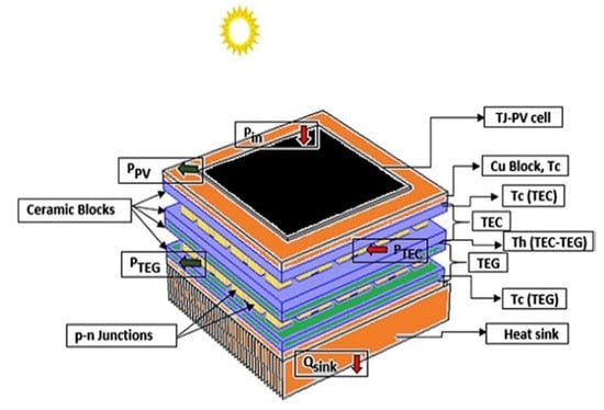
Figure 25.
COMSOL MULTIPHYSICS’s photovoltaic-thermoelectric (PV-TE) hybrid system model [42].
The traditional PV-TE hybrid system cannot always operate at the optimal operating temperature because of the fluctuation of the solar radiation. Thus Cui et al. (2016) [112] tried to utilise PCM to reduce the temperature variation. Unfortunately, the experimental results of Cui et al. (2017) [113] showed the PCM has less impact on the efficiency of the PV-PCM TE hybrid system. Under this circumstances Zhang and Xuan (2017) [114] proposed and experimentally tested a novel PV-TE hybrid system with adjustable cooling blocks under different concentrated radiation (from 15.8 to 31.4 W) to reduce the temperature fluctuation caused by variation of the solar radiation.
Four TE generators were designed and equipped with a water cooling block separately to utilize the generated heat. The cooling water is forced to flow through every water cooling block under high solar radiation, while at low solar radiation the cycles of water in some blocks was closed to reduce temperature variation. The schematic illustration of the experimental setup is shown as Figure 26. Experimental results demonstrated this novel PV-TE hybrid system could achieve a lower temperature fluctuation than traditional hybrid system, and the output power increased obviously by introducing the TE generator into the PV system [114].
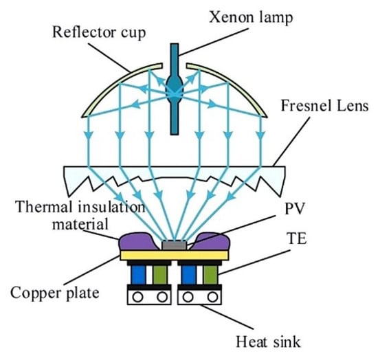
Figure 26.
Schematic illustration of the experimental setup of the novel PV-TE hybrid system [114].
Similarly, Mohsenzadeh et al. (2017) [115] experimentally investigated the novel concentrating PV/T collectors with TE modules, the whole system was cooled by water with the flow rate of 0.025 m/s. The cross-section schematic diagram is shown in Figure 27. In this integrated system, a larger portion of solar radiation was directly converted to electricity hence enhanced the performance, results showed that the daily average electrical and thermal efficiencies could reach 4.83% and 46.16% respectively with one-axis solar tracker. Measurements showed that the usage of glass cover tube on the receiver of the CPV/T+TE system reduced the heat dissipation to the ambient air and eventually increased the total efficiency, but it also increased the average PV cell temperature (7.89% higher than that of CPV/T+TE without cover hybrid system).
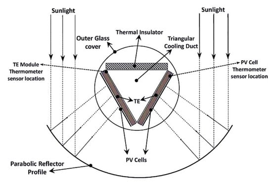
Figure 27.
Schematic diagram of the cross-section of CPV/T+TE hybrid collector [115].
Table 6 summaries the cogeneration power technologies mentioned above.

Table 6.
Summary of the cogeneration power technologies.
8. Future Prospect
Based on the existing literature, it is found that the majority of studies of the cooling systems for CPV systems are only being conducted from the technical direction, and there is an absence of research from the economics and environmental aspects. Whether the reduced power generation costs, causing by the cell efficiency improvement provided by cooling systems, can offset or exceed the cooling costs still needs to be investigated.
Limited research was found about the utilisation of heat pipe in CPV system cooling. And the heat pipe as a passive cooling device can only be used in low and medium concentration ratio. The potential of the heat pipe using for cooling CPV system can be further investigated. The Liquid immersion cooling can be used for high concentration ratio, but it has deposition problem of the salt that restrict its research potential in CPV cooling and need to be developed.
The characteristic of PCM for continuous supply of thermal energy provides a new research insight in CPV cooling field. But considering the high cost, the PCM can only be an option for widely used in CPV cooling in future after the material price drop. Thus the passive cooling technologies may focus on the research of hybrid cooling systems, which can express high cooling capacity also show other advantages. Such as hybrid jet impingement/micro-channel cooling device mention above.
The Ground-coupled Central Panel Cooling System and Earth Water Heat Exchanger Cooling take the advantage of the earth heat. Both of these two techniques are brand new aspects for cooling the CPV system that need to be developed. Based on gained results and existing technical solutions, both of them can realise cost and performance enhancement. Micro and Nano technologies show big potential in the CPV cooling field. The way of reducing the pumping power and pressure loss of these techniques has a significant influence on CPV system.
Cogeneration power technology is an example for combining the CPV system with other energy conversion systems. It was proved that it can maximise the utilisation of the waste heat that can decrease cell temperature and increase system output. The novel PV-TE hybrid system also has been proved can achieve a lower temperature fluctuation than traditional hybrid system. The combination of CPV with other systems provides a new perspective for improving system performance, reducing cell temperature and temperature fluctuation at the same time.
9. Conclusions
The concentrator photovoltaics concept makes the utilization of spectral separation technology cost-effective. And through the existing literature from the last few years can be found that multi-junction has attracted an ever rising attention and has been widely used in CPV system. But there is no available commercial tool to analyse the performance of CPV with multi-junction solar cell.
During the last few years, some new techniques have been commonly used in CPV system cooling, such as micro and nano technologies, jet impingement, liquid immersion, etc. Their high cooling capacity proceed the progress of resolving the overheat problems under the high concentration ratio. Currently, according to the gained results and existing technical solutions, the most viable passive cooling option, both from a technical and economic point of view, is the air-based cooling option with Al-fins mounted on the backside surface of the PV panel. Combining the technical and economic aspects, the air-based cooling systems mounted with metal fins on the backside of PV, is currently the most viable passive cooling technique for CPV cooling. As a heat sink material, aluminium has been found that performs better than copper in terms of weight and cost. The good thermal contact between batteries and aluminium plate is critical for cell temperature decrease and the design of heat sink has efficient impact on heat dissipation performance.
Microchannel heat sink shows the strong abilities in solar cell temperature reduction and uniform temperature distribution. And hybrid jet impingement/micro-channel cooling device can modify the internal geometry during the design stage to adapt the distribution of the heat removal capacity to improve the temperature uniformity, while the micro-channel design can only reduce the PV temperature by increasing the flow rate of coolant. At the aspect of average increase in efficiency, PCM based cooling systems are very similar to air-based cooling systems, while PCM are more expensive and complex to construct. Besides, the acidification impact of PCM to the environment is the most emphasized and highest in magnitude, whereas the least environment harmful technology is air cooling. But PCM can store and deliver the thermal energy on demand, take the maximum utilisation of waste heat can realise a win-win situation between cell temperature decrease and system output increase. The wasted heat of CPV-TE system was absorbed by the thermoelectric cooler and transferred to thermoelectric generator, and was converted into electricity with a maximum efficiency of 5% (which is the state-of-art of the device).
Concentrated photovoltaic (CPV) systems require efficient cooling devices to ensure the PV cell works within the nominal operating temperature range. The cooling system for CPV must to have low thermal resistance coefficients, also need to provide good cell temperature uniformity that can maximize the efficiency and maintain the reliability of the whole system. Besides, the factors of power consumption, convenient installation, and high reliability of cooling system should also be taken into consideration. The choice of the cooling technique depends on the target and actual situation. The recent development of various cooling technologies, including commonly used air cooling and water cooling, the promising Ground-coupled Cooling, Earth Water Heat Exchanger Cooling, Impinging Jet Cooling, Liquid Immersion Cooling, Microchannel Cooling, Heat Pipe Cooling and Phase Change Material systems etc., has been analysed in this work. It is expected that this paper could define the aspects that need to be considered in future developments.
Author Contributions
This work is the combined effort of both of the authors. M.X. collected the published literature about the fault diagnosis and wrote the initial manuscript; L.T. and X.Z., revised the manuscript and added their views; review and editing were done by I.Y.F.L. and Y.Y.
Funding
The authors would like to acknowledge their sincere appreciation for the financial support from Beijing Natural Science Foundation of China (Grant No. 3172041), Ningbo Science & Technology Bureau Innovation Team project (Grant No. 2015B11011) and the IDIC (International Doctoral Innovation Centre) program of the University of Nottingham Ningbo China.
Conflicts of Interest
The authors declare no conflicts of interest.
References
- Agency, I.E. World Energy Outlook 2010; International Energy Agency: Paris, France, 2010; p. 7. ISBN 9789264086241. [Google Scholar]
- Ummadisingu, A.; Soni, M.S. Concentrating solar power—Technology, potential and policy in India. Renew. Sustain. Energy Rev. 2011, 15, 5169–5175. [Google Scholar] [CrossRef]
- Soni, M.S.; Gakkhar, N. Techno-economic parametric assessment of solar power in India: A survey. Renew. Sustain. Energy Rev. 2014, 40, 326–334. [Google Scholar] [CrossRef]
- Gakkhar, N.; Soni, M.S.; Jakhar, S. Second law thermodynamic study of solar assisted distillation system: A review. Renew. Sustain. Energy Rev. 2016, 56, 519–535. [Google Scholar] [CrossRef]
- Agency, I.E. Technology Roadmap Solar Photovoltaic Energy; International Energy Agency: Paris, France, 2014. [Google Scholar]
- Hernandez, R.R.; Hoffacker, M.K.; Murphy-Mariscal, M.L.; Wu, G.C.; Allen, M.F. Solar energy development impacts on land cover change and protected areas. Proc. Natl. Acad. Sci. USA 2015, 112, 13579–13584. [Google Scholar] [CrossRef]
- Ong, S.; Campbell, C.; Denholm, P.; Margolis, R.; Heath, G. Land-Use Requirements for Solar Power Plants in the United States; National Laboratory of the U.S. Department of Energy: Washington, DC, USA, 2013.
- Pérez-Higueras, P.; Muñoz, E.; Almonacid, G.; Vidal, P.G. High Concentrator PhotoVoltaics efficiencies: Present status and forecast. Renew. Sustain. Energy Rev. 2011, 15, 1810–1815. [Google Scholar] [CrossRef]
- Lovegrove, K.; Csiro, W.S. 1—Introduction to concentrating solar power (CSP) technology. In Concentrating Solar Power Technology; Woodhead Publishing: Sawston, UK, 2012; pp. 3–15. [Google Scholar] [CrossRef]
- Soni, M.S.; Mellacheruvu, P. Concentrating Solar Photovoltaic. In Proceedings of the International Conference Advanced Energy Research, Mumbai, India, 10–12 December 2013; pp. 376–384. [Google Scholar]
- Solanki, C.S.; Sangani, C.S.; Gunashekar, D.; Antony, G. Enhanced heat dissipation of V-trough PV modules for better performance. Sol. Energy Mater. Sol. Cells 2008, 92, 1634–1638. [Google Scholar] [CrossRef]
- Turchi, C.; Mehos, M.; Ho, C.K.; Kolb, G.J. Current and Future Costs for Parabolic Trough and Power Tower Systems in the US Market. In Proceedings of the SolarPACES 2010, Perpignan, France, 21–24 September 2010. [Google Scholar]
- Goodrich, A.; James, T.; Woodhouse, M. Residential, commercial, and utility-scale photovoltaic (pv) system prices in the united states: Current drivers and cost-reduction opportunities. Contract 2012, 303, 275–3000. [Google Scholar]
- Mojiri, A.; Taylor, R.; Thomsen, E.; Rosengarten, G. Spectral beam splitting for efficient conversion of solar energy—A review. Renew. Sustain. Energy Rev. 2013, 28, 654–663. [Google Scholar] [CrossRef]
- Teo, H.G.; Lee, P.S.; Hawlader, M.N.A. An active cooling system for photovoltaic modules. Appl. Energy 2012, 90, 309–315. [Google Scholar] [CrossRef]
- Würfel, P.; Würfel, U. Physics of Solar Cells: From Basic Principles to Advanced Concepts; WILEY-VCH Verlag GmbH & Co. KGaA: Weinheim, Germany, 2009. [Google Scholar]
- Dubey, S.; Sarvaiya, J.N.; Seshadri, B. Temperature Dependent Photovoltaic (PV) Efficiency and Its Effect on PV Production in the World—A Review. Energy Procedia 2013, 33, 311–321. [Google Scholar] [CrossRef]
- He, W.; Chow, T.-T.; Ji, J.; Lu, J.; Pei, G.; Chan, L.-S. Hybrid photovoltaic and thermal solar-collector designed for natural circulation of water. Appl. Energy 2006, 83, 199–210. [Google Scholar] [CrossRef]
- Do, K.H.; Kim, T.H.; Han, Y.-S.; Choi, B.-I.; Kim, M.-B. General correlation of a natural convective heat sink with plate-fins for high concentrating photovoltaic module cooling. Sol. Energy 2012, 86, 2725–2734. [Google Scholar] [CrossRef]
- Wang, Y.; Liu, Z.; Chatsko, M.A.R.; Liu, S. Ethanol Fermentation by Escherichia Coli FBWHR Using Hot-Water Sugar Maple Wood Exact Hydrolyzate as Substrate: A Batch Fermentation and Kinetic Study. J. Bioprocess Eng. Biorefin. 2013, 2, 20–26. [Google Scholar] [CrossRef]
- Davidsson, H.; Perers, B.; Karlsson, B. Performance of a multifunctional PV/T hybrid solar window. Sol. Energy 2010, 84, 365–372. [Google Scholar] [CrossRef]
- Jakhar, S.; Soni, M.S.; Gakkhar, N. Historical and recent development of concentrating photovoltaic cooling technologies. Renew. Sustain. Energy Rev. 2016, 60, 41–59. [Google Scholar] [CrossRef]
- Wu, Y.; Connelly, K.; Liu, Y.; Gu, X.; Gao, Y.; Chen, G.Z. Smart solar concentrators for building integrated photovoltaic façades. Sol. Energy 2016, 133, 111–118. [Google Scholar] [CrossRef]
- Lu, W.; Wu, Y.; Eames, P. Design and development of a Building Façade Integrated Asymmetric Compound Parabolic Photovoltaic concentrator (BFI-ACP-PV). Appl. Energy 2018, 220, 325–336. [Google Scholar] [CrossRef]
- Mallick, T.K.; Eames, P.C. Electrical performance evaluation of low-concentrating non-imaging photovoltaic concentrator. Progress Photovolt. Res. Appl. 2008, 16, 389–398. [Google Scholar] [CrossRef]
- Kocher-Oberlehner, G.; Bardosova, M.; Pemble, M.; Richards, B.S. Planar photonic solar concentrators for building-integrated photovoltaics. Sol. Energy Mater. Sol. Cells 2012, 104, 53–57. [Google Scholar] [CrossRef]
- Gleckman, P. A high concentration rooftop photovoltaic system. Proc. SPIE 2007, 6649, 664903. [Google Scholar]
- Gleckman, P. Rooftop Photovoltaic System Using High Concentration: An Optical Perspective. In Proceedings of the Workshop on Concentrating Photovoltaic Power Plants: Optical Design and Grid Connection, Marburg, Germany, 11 October 2007. [Google Scholar]
- Sellami, N.; Mallick, T.K. Optical efficiency study of PV Crossed Compound Parabolic Concentrator. Appl. Energy 2013, 102, 868–876. [Google Scholar] [CrossRef]
- Li, W.; Paul, M.C.; Rolley, M.; Sweet, T.; Gao, M.; Baig, H.; Fernandez, E.F.; Mallick, T.K.; Montecucco, A.; Siviter, J.; et al. A coupled optical-thermal-electrical model to predict the performance of hybrid PV/T-CCPC roof-top systems. Renew. Energy 2017, 112, 166–186. [Google Scholar] [CrossRef]
- Abdelaziz, E.A.; Saidur, R.; Mekhilef, S. A review on energy saving strategies in industrial sector. Renew. Sustain. Energy Rev. 2011, 15, 150–168. [Google Scholar] [CrossRef]
- Lee, D.I.; Oh, G.S.; Baek, S.W. Development of a heating device using CPV and heat pipe. In Proceedings of the 10th International Conference on Heat Transfer, Fluid Mechanics and Thermodynamics, Orlando, FL, USA, 14–16 July 2014. [Google Scholar]
- Hasan, A.; McCormack, S.; Huang, M.; Norton, B. Energy and Cost Saving of a Photovoltaic-Phase Change Materials (PV-PCM) System through Temperature Regulation and Performance Enhancement of Photovoltaics. Energies 2014, 7, 1318–1331. [Google Scholar] [CrossRef]
- Huang, M.J.; Eames, P.C.; Norton, B. Phase change materials for limiting temperature rise in building integrated photovoltaics. Sol. Energy 2006, 80, 1121–1130. [Google Scholar] [CrossRef]
- Royne, A.; Dey, C.J.; Mills, D.R. Cooling of photovoltaic cells under concentrated illumination: A critical review. Sol. Energy Mater. Sol. Cells 2005, 86, 451–483. [Google Scholar] [CrossRef]
- Hasan, A.; Sarwar, J.; Shah, A.H. Concentrated photovoltaic: A review of thermal aspects, challenges and opportunities. Renew. Sustain. Energy Rev. 2018, 94, 835–852. [Google Scholar] [CrossRef]
- Hu, F.; Liu, Y.; Zhang, Q.; Chen, Z. Solar Concentration and Frequency Division Photovoltaic Photo-Thermal Comprehensive Utilization Device. CN103236463A, 7 August 2013. [Google Scholar]
- Taudien, J.Y.; Kern, L.A. Concentrating and spectrum splitting optical device in high efficiency CPV module with five bandgaps. Proc. SPIE 2013, 8821, 88210A. [Google Scholar]
- Van Sark, W.G.J.H.M.; Barnham, K.W.J.; Slooff, L.H.; Chatten, A.J.; Büchtemann, A.; Meyer, A.; McCormack, S.J.; Koole, R.; Farrell, D.J.; Bose, R.; et al. Luminescent solar concentrators—A review of recent results. Opt. Express 2008, 16, 21773–21792. [Google Scholar] [CrossRef]
- Zhu, L.; Yoshita, M.; Nakamura, T.; Imaizumi, M.; Kim, C.; Mochizuki, T.; Chen, S.; Kanemitsu, Y.; Akiyama, H. Characterization and modeling of radiation damages via internal radiative efficiency in multi-junction solar cells. Phys. Simul. Photonic Eng. Photovolt. Devices V 2016, 9743, 97430U. [Google Scholar]
- Rey-Stolle, I.; Olson, J.M.; Algora, C. Concentrator Multijunction Solar Cells. In Handbook of Concentrator Photovoltaic Technology; John Wiley & Sons, Ltd.: Hoboken, NJ, USA, 2016; pp. 59–136. [Google Scholar] [CrossRef]
- Teffah, K.; Zhang, Y. Modeling and experimental research of hybrid PV-thermoelectric system for high concentrated solar energy conversion. Sol. Energy 2017, 157, 10–19. [Google Scholar] [CrossRef]
- Sadewasser, S.; Salomé, P.M.P.; Rodriguez-Alvarez, H. Materials efficient deposition and heat management of CuInSe2 micro-concentrator solar cells. Sol. Energy Mater. Sol. Cells 2017, 159, 496–502. [Google Scholar] [CrossRef]
- Burhan, M.; Shahzad, M.W.; Ng, K.C. Development of performance model and optimization strategy for standalone operation of CPV-hydrogen system utilizing multi-junction solar cell. Int. J. Hydrogen Energy 2017, 42, 26789–26803. [Google Scholar] [CrossRef]
- Stefancich, M.; Zayan, A.; Chiesa, M.; Rampino, S.; Roncati, D.; Kimerling, L.; Michel, J. Single element spectral splitting solar concentrator for multiple cells CPV system. Opt. Express 2012, 20, 9004–9018. [Google Scholar] [CrossRef]
- Vincenzi, D.; Busato, A.; Stefancich, M.; Martinelli, G. Concentrating PV system based on spectral separation of solar radiation. Physica Status Solidi A 2009, 206, 375–378. [Google Scholar] [CrossRef]
- Orosz, M.; Zweibaum, N.; Lance, T.; Ruiz, M.; Morad, R. Spectrum-splitting hybrid CSP-CPV solar energy system with standalone and parabolic trough plant retrofit applications. AIP Conf. Proc. 2016, 1734, 070023. [Google Scholar]
- Widyolar, B.; Jiang, L.; Winston, R. Spectral beam splitting in hybrid PV/T parabolic trough systems for power generation. Appl. Energy 2018, 209, 236–250. [Google Scholar] [CrossRef]
- Yaping, J.; Ollanik, A.; Farrar-Foley, N.; Qi, X.; Madrone, L.; Lynn, P.; Romanin, V.; Codd, D.; Escarra, M. Transmissive spectrum splitting multi-junction solar module for hybrid CPV/CSP system. In Proceedings of the 2015 IEEE 42nd Photovoltaic Specialist Conference (PVSC), New Orleans, LA, USA, 14–19 June 2015; pp. 1–5. [Google Scholar]
- Widyolar, B.K.; Abdelhamid, M.; Jiang, L.; Winston, R.; Yablonovitch, E.; Scranton, G.; Cygan, D.; Abbasi, H.; Kozlov, A. Design, simulation and experimental characterization of a novel parabolic trough hybrid solar photovoltaic/thermal (PV/T) collector. Renew. Energy 2017, 101, 1379–1389. [Google Scholar] [CrossRef]
- Sun, X.; Silverman, T.J.; Zhou, Z.; Khan, M.R.; Bermel, P.; Alam, M.A. Optics-Based Approach to Thermal Management of Photovoltaics: Selective-Spectral and Radiative Cooling. IEEE J. Photovolt. 2017, 7, 566–574. [Google Scholar] [CrossRef]
- Chen, J.; Yang, L.; Zhang, Z.; Wei, J.; Yang, J. Optimization of a uniform solar concentrator with absorbers of different shapes. Sol. Energy 2017, 158, 396–406. [Google Scholar] [CrossRef]
- Anton, I.; Sala, G.; Pachon, D. Correction of the Voc vs. temperature dependence under non-uniform concentrated illumination. In Proceedings of the 17th European Photovoltaic Solar Energy Conference, Munich, Germany, 22–26 October 2001; pp. 156–159. [Google Scholar]
- Shakouri, A.; Yan, Z. On-chip solid-state cooling for integrated circuits using thin-film microrefrigerators. IEEE Trans. Compon. Packag. Technol. 2005, 28, 65–69. [Google Scholar] [CrossRef]
- Baig, H.; Heasman, K.C.; Mallick, T.K. Non-uniform illumination in concentrating solar cells. Renew. Sustain. Energy Rev. 2012, 16, 5890–5909. [Google Scholar] [CrossRef]
- Edenburn, M.W.; Burns, J.R. Shading analysis of a photovoltaicc ell string illuminated by a parabolic through concentrator. In Proceedings of the 15th IEEE PVSC, Orlando, FL, USA, 11–15 May 1981; pp. 63–68. [Google Scholar]
- Faiman, D. Large-area concentrators. In Proceedings of the Second Workshop on the Path to Ultrahigh Efficiency Photovoltaics, JRC-Ispra, Italy, 3–4 October 2002. [Google Scholar]
- Hosenuzzaman, M.; Rahim, N.A.; Selvaraj, J.; Hasanuzzaman, M.; Malek, A.B.M.A.; Nahar, A. Global prospects, progress, policies, and environmental impact of solar photovoltaic power generation. Renew. Sustain. Energy Rev. 2015, 41, 284–297. [Google Scholar] [CrossRef]
- Cucchiella, F.; D’Adamo, I.; Rosa, P. End-of-Life of used photovoltaic modules: A financial analysis. Renew. Sustain. Energy Rev. 2015, 47, 552–561. [Google Scholar] [CrossRef]
- Bahaidarah, H.M.S.; Baloch, A.A.B.; Gandhidasan, P. Uniform cooling of photovoltaic panels: A review. Renew. Sustain. Energy Rev. 2016, 57, 1520–1544. [Google Scholar] [CrossRef]
- Gray, A.; Boehm, R.; Stone, K.W. Modeling a Passive Cooling System for Photovoltaic Cells Under Concentration. In Proceedings of the ASME/JSME 2007 Thermal Engineering Heat Transfer Summer Conference, Vancouver, BC, Canada, 8–12 July 2007; pp. 447–454. [Google Scholar] [CrossRef]
- Cui, M.; Chen, N.; Yang, X.; Wang, Y.; Bai, Y.; Zhang, X. Thermal analysis and test for single concentrator solar cells. J. Semicond. 2009, 30, 044011. [Google Scholar]
- Sun, J.; Israeli, T.; Reddy, T.A.; Scoles, K.; Gordon, J.M.; Feuermann, D. Modeling and experimental evaluation of passive heat sinks for miniature high-flux photovoltaic concentrators. J. Sol. Energy Eng. 2005, 127, 138–145. [Google Scholar] [CrossRef]
- Cheknane, A.; Benyoucef, B.; Chaker, A. Performance of concentrator solar cells with passive cooling. Semicond. Sci. Technol. 2006, 21, 144. [Google Scholar] [CrossRef]
- Yeom, J.; Shannon, M.A. 3.16—Micro-Coolers A2—Gianchandani, Yogesh B. In Comprehensive Microsystems; Tabata, O., Zappe, H., Eds.; Elsevier: Oxford, UK, 2008; pp. 499–550. [Google Scholar] [CrossRef]
- Mallick, T.K.; Eames, P.C.; Norton, B. Using air flow to alleviate temperature elevation in solar cells within asymmetric compound parabolic concentrators. Sol. Energy 2007, 81, 173–184. [Google Scholar] [CrossRef]
- Tonui, J.K.; Tripanagnostopoulos, Y. Air-cooled PV/T solar collectors with low cost performance improvements. Sol. Energy 2007, 81, 498–511. [Google Scholar] [CrossRef]
- Brinkworth, B.J.; Sandberg, M. Design procedure for cooling ducts to minimize efficiency loss due to temperature rise in PV arrays. Sol. Energy 2006, 80, 89–103. [Google Scholar] [CrossRef]
- Kraus, A.D.; Bar-Cohen, A. Design and Analysis of Heat Sinks; Wiley-Interscience: New York, NY, USA, 1995. [Google Scholar]
- Araki, K.; Uozumi, H.; Yamaguchi, M. A simple passive cooling structure and its heat analysis for 500/spl times/concentrator PV module. In Proceedings of the Twenty-Ninth IEEE Photovoltaic Specialists Conference, New Orleans, LA, USA, 19–24 May 2002. [Google Scholar]
- Mittelman, G.; Dayan, A.; Dado-Turjeman, K.; Ullmann, A. Laminar free convection underneath a downward facing inclined hot fin array. Int. J. Heat Mass Transf. 2007, 50, 2582–2589. [Google Scholar] [CrossRef]
- Aldossary, A.; Mahmoud, S.; Al-Dadah, R. Technical feasibility study of passive and active cooling for concentrator PV in harsh environment. Appl. Therm. Eng. 2016, 100, 490–500. [Google Scholar] [CrossRef]
- Micheli, L.; Reddy, K.S.; Mallick, T.K. Plate Micro-fins in Natural Convection: An Opportunity for Passive Concentrating Photovoltaic Cooling. Energy Procedia 2015, 82, 301–308. [Google Scholar] [CrossRef]
- Cooper, T.; Dähler, F.; Ambrosetti, G.; Pedretti, A.; Steinfeld, A. Performance of compound parabolic concentrators with polygonal apertures. Sol. Energy 2013, 95, 308–318. [Google Scholar] [CrossRef]
- Mammo, E.D.; Sellami, N.; Mallick, T.K. Performance analysis of a reflective 3D crossed compound parabolic concentrating photovoltaic system for building façade integration. Prog. Photovolt. Res. Appl. 2013, 21, 1095–1103. [Google Scholar] [CrossRef]
- Li, W.; Paul, M.C.; Sellami, N.; Mallick, T.K.; Knox, A.R. Natural convective heat transfer in a walled CCPC with PV cell. Case Stud. Therm. Eng. 2017, 10, 499–516. [Google Scholar] [CrossRef]
- Han, X.; Wang, Y.; Zhu, L. The performance and long-term stability of silicon concentrator solar cells immersed in dielectric liquids. Energy Convers. Manag. 2013, 66, 189–198. [Google Scholar] [CrossRef]
- Xin, G.; Wang, Y.; Sun, Y.; Huang, Q.; Zhu, L. Experimental study of liquid-immersion III–V multi-junction solar cells with dimethyl silicon oil under high concentrations. Energy Convers. Manag. 2015, 94, 169–177. [Google Scholar] [CrossRef]
- Kang, X.; Wang, Y.; Huang, Q.; Cui, Y.; Shi, X.; Sun, Y. Study on direct-contact phase-change liquid immersion cooling dense-array solar cells under high concentration ratios. Energy Convers. Manag. 2016, 128, 95–103. [Google Scholar] [CrossRef]
- Peterson, G.P. An Introduction to Heat Pipes: Modeling, Testing, and Applications; John Wiley & Sons: Etobicoke, ON, Canada, 1994. [Google Scholar]
- Anderson, W.G.; Dussinger, P.M.; Sarraf, D.B.; Tamanna, S. Heat pipe cooling of concentrating photovoltaic cells. In Proceedings of the 2008 33rd IEEE Photovoltaic Specialists Conference, San Diego, CA, USA, 11–16 May 2008; pp. 1–6. [Google Scholar]
- Huang, H.-J.; Shen, S.-C.; Shaw, H.-J. Design and Fabrication of a Novel Hybrid-Structure Heat Pipe for a Concentrator Photovoltaic. Energies 2012, 5, 4340–4349. [Google Scholar] [CrossRef]
- Kandasamy, R.; Wang, X.-Q.; Mujumdar, A.S. Application of phase change materials in thermal management of electronics. Appl. Therm. Eng. 2007, 27, 2822–2832. [Google Scholar] [CrossRef]
- Sharma, S.; Tahir, A.; Reddy, K.S.; Mallick, T.K. Performance enhancement of a Building-Integrated Concentrating Photovoltaic system using phase change material. Sol. Energy Mater. Sol. Cells 2016, 149, 29–39. [Google Scholar] [CrossRef]
- Emam, M.; Ookawara, S.; Ahmed, M. Performance study and analysis of an inclined concentrated photovoltaic-phase change material system. Sol. Energy 2017, 150, 229–245. [Google Scholar] [CrossRef]
- Su, Y.; Zhang, Y.; Shu, L. Experimental study of using phase change material cooling in a solar tracking concentrated photovoltaic-thermal system. Sol. Energy 2018, 159, 777–785. [Google Scholar] [CrossRef]
- Al-Amri, F.; Mallick, T.K. Alleviating operating temperature of concentration solar cell by air active cooling and surface radiation. Appl. Therm. Eng. 2013, 59, 348–354. [Google Scholar] [CrossRef]
- Al-Amri, F.; Mallick, T.K. Effects of Nonuniform Incident Illumination on the Thermal Performance of a Concentrating Triple Junction Solar Cell. Int. J. Photoenergy 2014, 2014, 12. [Google Scholar] [CrossRef]
- Wang, S.; Shi, J.; Chen, H.-H.; Schafer, S.R.; Munir, M.; Stecker, G.; Pan, W.; Lee, J.-J.; Chen, C.-L. Cooling design and evaluation for photovoltaic cells within constrained space in a CPV/CSP hybrid solar system. Appl. Therm. Eng. 2017, 110, 369–381. [Google Scholar] [CrossRef]
- Du, B.; Hu, E.; Kolhe, M. Performance analysis of water cooled concentrated photovoltaic (CPV) system. Renew. Sustain. Energy Rev. 2012, 16, 6732–6736. [Google Scholar] [CrossRef]
- Sabry, M. Temperature optimization of high concentrated active cooled solar cells. NRIAG J. Astron. Geophys. 2016, 5, 23–29. [Google Scholar] [CrossRef]
- Chaabane, M.; Mhiri, H.; Bournot, P. Performance Optimization of Water-Cooled Concentrated Photovoltaic System. Heat Transf. Eng. 2016, 37, 76–81. [Google Scholar] [CrossRef]
- Sahay, A.; Sethi, V.K.; Tiwari, A.C. Design, optimisation and system integration of low cost Ground Coupled Central Panel Cooling System (GC-CPCS). Int. J. Curr. Eng. Technol. 2013, 3, 1473–1479. [Google Scholar]
- Sahay, A.; Sethi, V.K.; Tiwari, A.C.; Pandey, M. A review of solar photovoltaic panel cooling systems with special reference to Ground coupled central panel cooling system (GC-CPCS). Renew. Sustain. Energy Rev. 2015, 42, 306–312. [Google Scholar] [CrossRef]
- Jakhar, S.; Soni, M.S.; Gakkhar, N. Performance Analysis of Earth Water Heat Exchanger for Concentrating Photovoltaic Cooling. Energy Procedia 2016, 90, 145–153. [Google Scholar] [CrossRef]
- Jakhar, S.; Soni, M.S.; Gakkhar, N. Modelling and Simulation of Concentrating Photovoltaic System with Earth Water Heat Exchanger Cooling. Energy Procedia 2017, 109, 78–85. [Google Scholar] [CrossRef]
- Jakhar, S.; Soni, M.S.; Gakkhar, N. An integrated photovoltaic thermal solar (IPVTS) system with earth water heat exchanger cooling: Energy and exergy analysis. Sol. Energy 2017, 157, 81–93. [Google Scholar] [CrossRef]
- Radwan, A.; Ookawara, S.; Ahmed, M. Analysis and simulation of concentrating photovoltaic systems with a microchannel heat sink. Sol. Energy 2016, 136, 35–48. [Google Scholar] [CrossRef]
- Yang, K.; Zuo, C. A novel multi-layer manifold microchannel cooling system for concentrating photovoltaic cells. Energy Convers. Manag. 2015, 89, 214–221. [Google Scholar] [CrossRef]
- Radwan, A.; Ahmed, M.; Ookawara, S. Performance enhancement of concentrated photovoltaic systems using a microchannel heat sink with nanofluids. Energy Convers. Manag. 2016, 119, 289–303. [Google Scholar] [CrossRef]
- Rohsenow, W.M.; Hartnett, J.P.; Cho, Y.I. Handbook of Heat Transfer, 3rd ed.; McGraw-Hill: New York, NY, USA, 1998. [Google Scholar]
- Royne, A.; Dey, C.J. Design of a jet impingement cooling device for densely packed PV cells under high concentration. Sol. Energy 2007, 81, 1014–1024. [Google Scholar] [CrossRef]
- Barrau, J.; Rosell, J.; Chemisana, D.; Tadrist, L.; Ibañez, M. Effect of a hybrid jet impingement/micro-channel cooling device on the performance of densely packed PV cells under high concentration. Sol. Energy 2011, 85, 2655–2665. [Google Scholar] [CrossRef]
- Barrau, J.; Perona, A.; Dollet, A.; Rosell, J. Outdoor test of a hybrid jet impingement/micro-channel cooling device for densely packed concentrated photovoltaic cells. Sol. Energy 2014, 107, 113–121. [Google Scholar] [CrossRef]
- Benghanem, M.; Al-Mashraqi, A.A.; Daffallah, K.O. Performance of solar cells using thermoelectric module in hot sites. Renew. Energy 2016, 89, 51–59. [Google Scholar] [CrossRef]
- Dallan, B.S.; Schumann, J.; Lesage, F.J. Performance evaluation of a photoelectric–thermoelectric cogeneration hybrid system. Sol. Energy 2015, 118, 276–285. [Google Scholar] [CrossRef]
- Zhang, Y.; Fang, J.; He, C.; Yan, H.; Wei, Z.; Li, Y. Integrated energy-harvesting system by combining the advantages of polymer solar cells and thermoelectric devices. J. Phys. Chem. C 2013, 117, 24685–24691. [Google Scholar] [CrossRef]
- Chávez-Urbiola, E.; Vorobiev, Y.V.; Bulat, L. Solar hybrid systems with thermoelectric generators. Sol. Energy 2012, 86, 369–378. [Google Scholar] [CrossRef]
- Huen, P.; Daoud, W.A. Advances in hybrid solar photovoltaic and thermoelectric generators. Renew. Sustain. Energy Rev. 2017, 72, 1295–1302. [Google Scholar] [CrossRef]
- Lee, J.J.; Yoo, D.; Park, C.; Choi, H.H.; Kim, J.H. All organic-based solar cell and thermoelectric generator hybrid device system using highly conductive PEDOT: PSS film as organic thermoelectric generator. Sol. Energy 2016, 134, 479–483. [Google Scholar] [CrossRef]
- Attivissimo, F.; Di Nisio, A.; Lanzolla, A.M.L.; Paul, M. Feasibility of a photovoltaic–thermoelectric generator: Performance analysis and simulation results. IEEE Trans. Instrum. Meas. 2015, 64, 1158–1169. [Google Scholar] [CrossRef]
- Cui, T.; Xuan, Y.; Li, Q. Design of a novel concentrating photovoltaic–thermoelectric system incorporated with phase change materials. Energy Convers. Manag. 2016, 112, 49–60. [Google Scholar] [CrossRef]
- Cui, T.; Xuan, Y.; Yin, E.; Li, Q.; Li, D. Experimental investigation on potential of a concentrated photovoltaic-thermoelectric system with phase change materials. Energy 2017, 122, 94–102. [Google Scholar] [CrossRef]
- Zhang, J.; Xuan, Y. Performance improvement of a photovoltaic—Thermoelectric hybrid system subjecting to fluctuant solar radiation. Renew. Energy 2017, 113, 1551–1558. [Google Scholar] [CrossRef]
- Mohsenzadeh, M.; Shafii, M.B.; Jafari Mosleh, H. A novel concentrating photovoltaic/thermal solar system combined with thermoelectric module in an integrated design. Renew. Energy 2017, 113, 822–834. [Google Scholar] [CrossRef]
© 2018 by the authors. Licensee MDPI, Basel, Switzerland. This article is an open access article distributed under the terms and conditions of the Creative Commons Attribution (CC BY) license (http://creativecommons.org/licenses/by/4.0/).