Article

Performance Study of a Novel Integrated Solar Combined Cycle System

Key Laboratory of Condition Monitoring and Control for Power Plant Equipment of Ministry of Education, National Thermal Power Engineering & Technology Research Center, School of Energy, Power and Mechanical Engineering, North China Electric Power University, Beijing 102206, China
*
Author to whom correspondence should be addressed.
Energies 2018, 11(12), 3400; https://doi.org/10.3390/en11123400
Submission received: 1 November 2018 / Revised: 27 November 2018 / Accepted: 1 December 2018 / Published: 4 December 2018
(This article belongs to the Section F: Electrical Engineering)

Abstract

:
Based on a traditional integrated solar combined cycle system, a novel integrated solar combined cycle (ISCC) system is proposed, which preferentially integrates the solar energy driven lithium bromide absorption refrigeration system that is used to cool the gas turbine inlet air in this paper. Both the Aspen Plus and EBSILON softwares are used to build the models of the overall system. Both the thermodynamic performance and economic performance of the new system are compared with those of the traditional ISCC system without the inlet air cooling process. The new system can regulate the proportions of solar energy integrated in the refrigerator and the heat recovery steam generator (HRSG) based on the daily meteorological data, and the benefits of the solar energy integrated with the absorption refrigeration are greater than with the HRSG. The results of both the typical day performance and annual performance of different systems show that the new system has higher daily and annual system thermal efficiencies (52.90% and 57.00%, respectively), higher daily and annual solar photoelectric efficiencies (31.10% and 22.31%, respectively), and higher daily and annual solar photoelectric exergy efficiencies (33.30% and 23.87%, respectively) than the traditional ISCC system. The solar energy levelized cost of electricity of the new ISCC system is 0.181 $/kW·h, which is 0.061 $/kW·h lower than that of the traditional ISCC system.

1. Introduction

Currently, air pollution and climate change problems due to the massive use of fossil fuels are increasing rapidly [1]. To solve these problems, the most effective solution is the massive use of renewable energy [2]. Among the various forms of renewable energy, solar energy has become one of the most promising energy sources due to its nearly unlimited reserves and clean and pollution-free characteristics, and solar thermal power generation is regarded as the most reasonable and effective technology. However, the independent solar thermal power generation technology has some inherent problems such as high cost, unstable operation, low solar photoelectric efficiency and low solar thermoelectric efficiency. Integrating solar energy with traditional fossil fuel-fired power generation systems has become an effective way to further reduce the use of fossil fuel, improve the thermal performance of the traditional power generation system and exploit solar energy. The integrated solar combined cycle (ISCC) system was initially proposed by Johansson TB et al. [3] in the early 1990s. Solar energy was coupled with the traditional gas turbine combined cycle (GTCC) system. It has been proven that the ISCC system can improve solar photoelectric efficiency, save the investment cost and reduce the fossil fuel consumption by integrating the solar energy [4,5]. Now the ISCC system has been applied and demonstrated around the world and is developing larger capacity and higher efficiency [6].
The thermodynamic performance of the first ISCC system built in Angola was analyzed by Omar Behar et al. [7]. The study showed that the ISCC system output power increased by 17% and the thermal cycle efficiency increased by 16.5% compared with the traditional GTCC system. M.J. Montes and Rovira [8] designed an ISCC system with the direct steam generation system (DSG) and compared it with the ISCC system with the heat transfer fluid (HTF). They concluded that the DSG technology had advantages in thermodynamic and economic performances. Antonio Rovira [9] et al. studied the performances of integrating the solar energy into different boiler heating surfaces of the combined cycle system with DSG. The results showed that the integration of high-pressure heating surfaces had higher thermal efficiency than the integration of low-pressure heating surfaces and the single integration with the high-pressure evaporator had advantages in both the thermodynamic performance and cost. A. Baghernejad and M. Yaghoubi [10] analyzed the exergy economic performance and sensitivity of the ISCC system with HTF trough solar technology and obtained a series of system optimization measures. A. Baghernejad, M. Yaghoubi [11] and G.C. Bakos, D. Parsa [12] have made some economic performance analyses of solar energy trough technology integrated with the Rankine cycle. They analyzed the process of exergy loss and revealed the relationships between the cost of electricity and integration modes. Yuanyuan Li [13,14] proposed a novel two-stage ISCC system. The results showed that the system had better thermodynamic performance. Giovanni Manente and Sergio Rech et al. [15] made thermodynamic and exergy analyses on different heating surfaces of the solar energy integrated into the high-pressure feeding water supply section of the heat recovery steam generator (HRSG) and found that the high pressure boiler (HPB) in the solar single-stage integrated HRSG had higher photoelectric conversion efficiency and output power. The simulation results from Popov [16] showed that with enough direct normal irradiance (DNI), for single-pressure or dual-pressure HRSG, the higher the pressure of the solar energy integration section was, the greater the energy level of the solar energy was, and the higher the thermoelectric conversion efficiency was. Omar Aboelwafa and Seif-Eddeen K. Fateen et al. [17] reviewed the researches on the solar Rankine cycle systems for power generation and focused on the working fluids and the application of these systems in water pumping and water desalination.
As we know, the ambient temperature has an important effect on the power output of the gas turbine. The maximum volume flow rate of the air compressor is limited by the inlet cross-section. Therefore, the volume flow rate of the air compressor remains almost unchanged. With the same inlet volume, the air density will be increased by cooling the inlet air temperature of the compressor. So, with the increase of the ambient temperature, the inlet air mass flow rate is greatly reduced. For the GTCC system, the thermodynamic performance of the gas turbine greatly depends on the ambient temperature [18].
For the gas turbine inlet air cooling technologies, there are many different technologies, such as refrigeration cooling (vapor compression chillers and absorption), fogging systems and evaporative cooling, that have been studied by researchers. Among them, the absorption refrigeration method can be realized by using the waste heat of the power plant, and then cold energy is provided to the gas turbine (GT). Li-Br absorption refrigeration and ammonia absorption refrigeration are two typical absorption refrigeration types. The Iranian Chababar power station adopted the Li-Br absorption refrigeration technology, generating power of more than 14,000 W·h per year, an increase of 11.3% in output power and an internal rate of return of 23.4%. China’s Shenzhen Jingang power plant also uses the Li-Br absorption refrigeration technology, so that the PG6541B gas turbine inlet temperature can be reduced from 31 °C to 17 °C.
Bhavesh Patel, Nishith B. Desai et al. [19] proposed and analyzed a novel solar-biomass organic Rankine cycle (ORC) powered cascaded vapor compression–absorption system, and the result shows that compared with the standalone cooling and heating, the system has higher cooling capacity, and the system can avail itself of the advantages of a lower break-even point and better thermo-economic performance. Evangelos Bellos and Christos Tzivanidis [20] analyzed a solar-driven trigeneration system with parabolic trough collectors, and the system was evaluated in energetic and exergetic terms. The results showed that the use of nanofluids as working fluids in the solar field can lead to a higher exergetic performance in trigeneration systems.
Popov [21] proposed and compared two ISCC layouts with inlet temperature cooling, and analyzed its thermodynamic performance at deign point and its cost advantages. The research results showed that a system with an absorption refrigerator has a lower levelized cost of electricity than the traditional ISCC system.
This paper presents a novel ISCC system, which use the solar thermal energy integrated into the chiller for cooling the gas turbine inlet temperature and the HRSG for increasing the system power output simultaneously. Based on the changes of the environmental temperature and DNI, the new system preferentially integrates solar energy into the Li-Br absorption refrigeration system. When the gas turbine inlet temperature drops to 5 °C, then the redundant collector mirrors are integrated into the HPB section of the HRSG. Through the performance calculations of a typical summer’s day and a typical year, both the thermodynamic and economic advantages of the new system are deeply analyzed.
2. System Description

2.1. The Traditional ISCC System

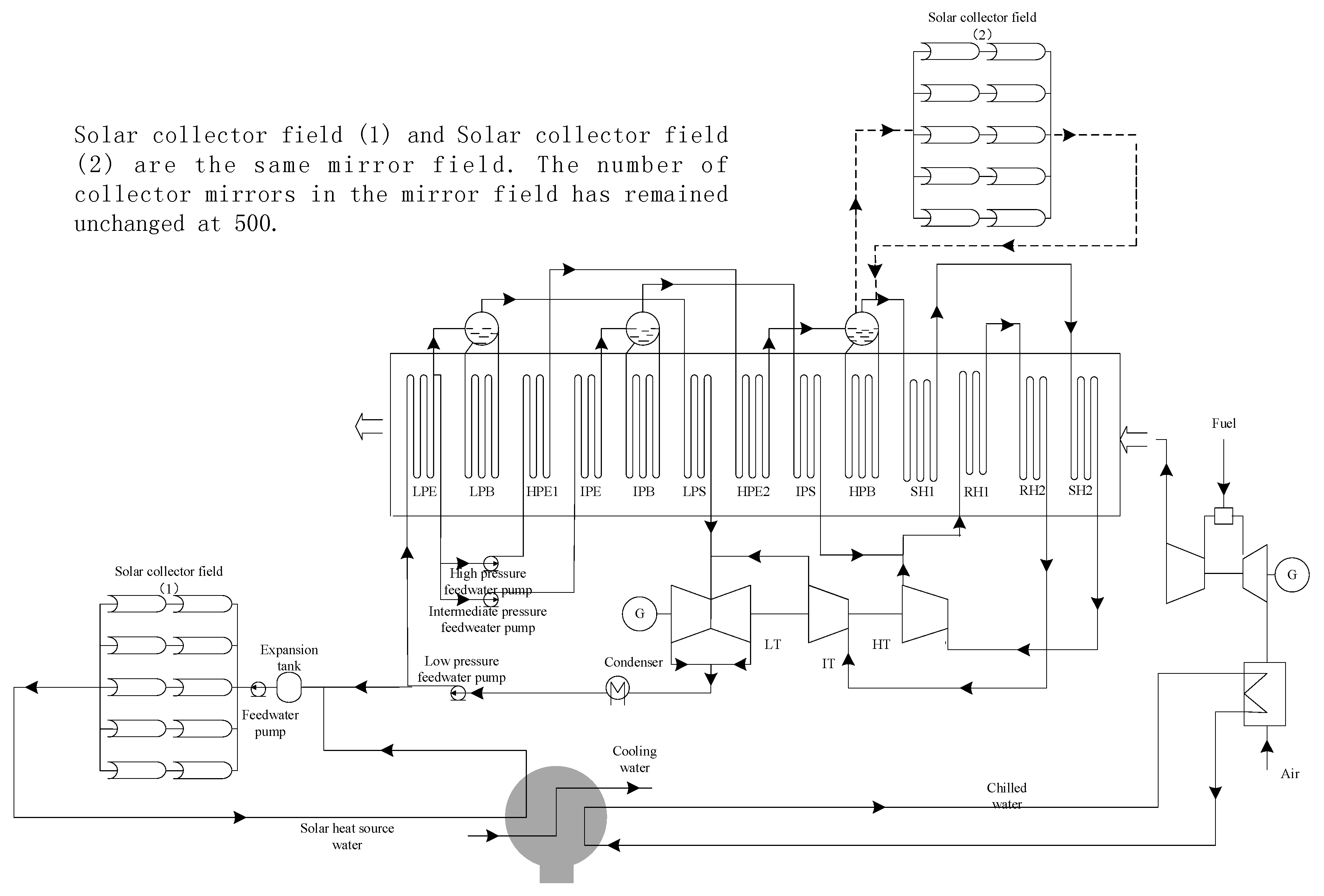
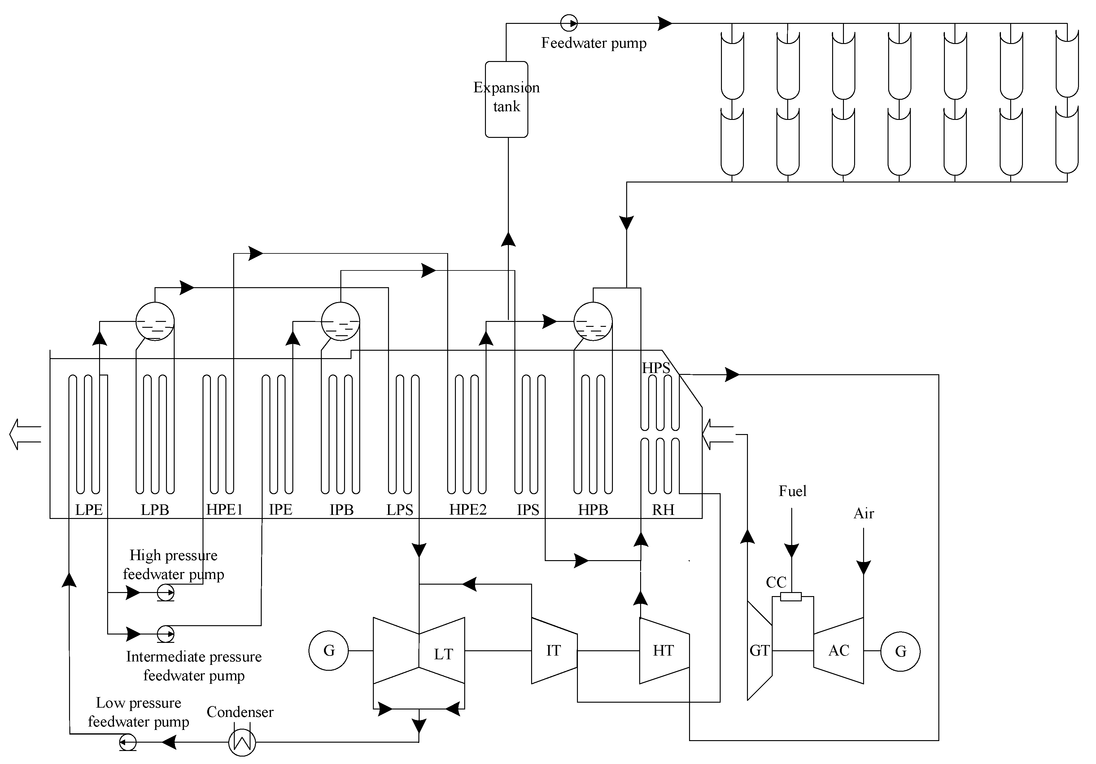
Figure 1 shows the traditional ISCC system flowchart. The ISCC system use the DSG technology with a trough parabolic field. The trough solar collector system is intergraded into the HPB section of the HRSG using the DSG technology. The working medium (water) is divided into two parts by the high pressure economizer 2 (HPE2). One part flows into the HPB, and the other part flows into the parabolic trough collectors (PTC) to absorb the solar thermal energy. Finally, these two parts mix and enter into the HRSG to be superheated. As shown in Figure 1, HP is the high pressure, IP is the intermediate pressure, LP is the low pressure, S is the superheater, B is the boiler, E is the economizer, RH is the reheater, CC is the combustion chamber, AC is the air compressor, GT is the gas turbine, HT is the high pressure steam turbine, IT is the intermediate pressure steam turbine, LT is the low pressure steam turbine, and G is the generator.

2.2. The New System

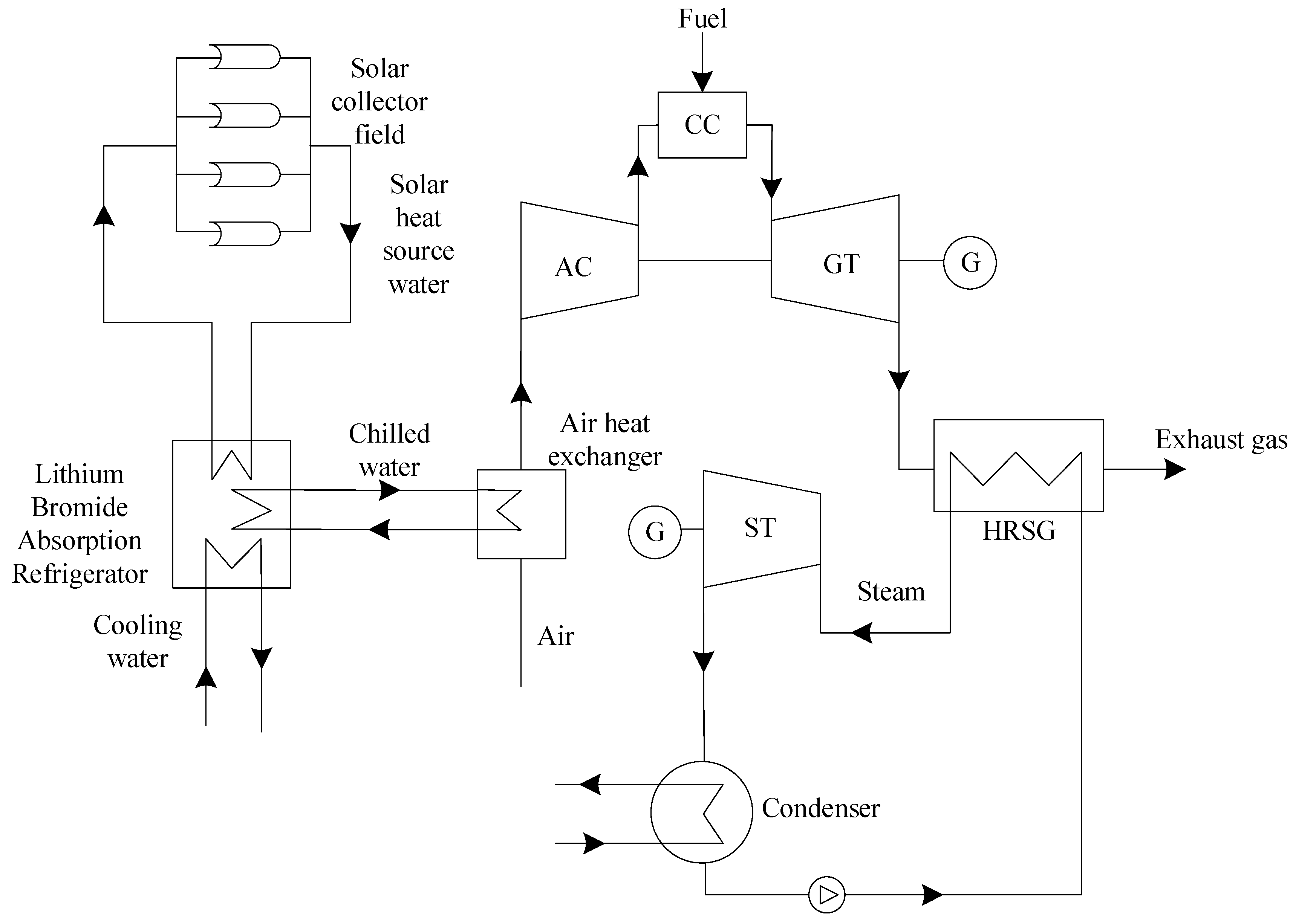
The Li-Br absorption refrigerator has the advantages of a simple structure, fewer moving parts, a wider range of cooling and good environmental performance, so it is widely used at present. At the same time, it has a larger cooling capacity compared with the ammonia–water absorption refrigerator and is more suitable for the gas turbine inlet air cooling which requires a larger cooling capacity. The literature [22] proposes an integration system which integrates the solar-driven single effect Li-Br absorption refrigeration into GTCC. As shown in Figure 2, the refrigeration system produces the heat source water for driving the absorption refrigerator, and the compressor inlet air is cooled by the produced chilled water.
The integration of chiller with gas turbine may solve a series of problems caused by the increase of ambient temperature. However, the operating temperature of Li-Br absorption refrigerator should be above 5 °C. And the surface air cooler will frost under the triple point temperature of water, which greatly reduces the heat transfer efficiency. So, the simple cooling system proposed by the literature [22] cannot operate in winter and other periods when the environmental temperature is too low. The solar energy-driven chiller combined cycle (SCCC) system has a lower annual solar energy utilization rate.
Thus, a new system is proposed in this paper. The new system is based on the traditional ISCC system, in which the solar thermal energy is integrated into the chiller for cooling the gas turbine inlet air and the HRSG for increasing the system power output simultaneously. Based on the changes in the environmental temperature and DNI, the new system preferentially integrates solar energy into the Li-Br absorption refrigeration system. The new system can regulate the proportions of solar energy used in the chiller system and HRSG based on the per half month meteorological data, which preferentially integrates the solar energy into the Li-Br absorption refrigeration system. The proposed system not only increases the solar photoelectric efficiency but also reduces the solar energy levelized cost of electricity. Figure 3 shows the new system flowchart of simultaneous integration of solar energy into the absorption refrigerator and HRSG system of the combined cycle.

3. Design Conditions and Mathematical Model

3.1. Solar Collector Subsystem

This paper applies the parabolic trough collectors with the LS-2 type produced by Luz International Limited company. The trough solar thermal field model is referenced to the 30 MW SEGS V1 power plant in the United States. The parabolic trough solar mirror field parameters are listed in Table 1.

3.2. GTCC Design Conditions

The PG9351FA gas turbine design data are listed in Table 2. The traditional GTCC system simulation results are listed in Table 3. The relative errors between the simulation results and the data in Reference [22] are less than 2%, as shown in Table 4. The simulation result and the design parameter error are within the allowable range, so the system simulation model is reliable.

3.3. Single-Effect Li-Br Absorption Refrigeration System

3.3.1. Basic Form of the Absorption Refrigeration Cycle

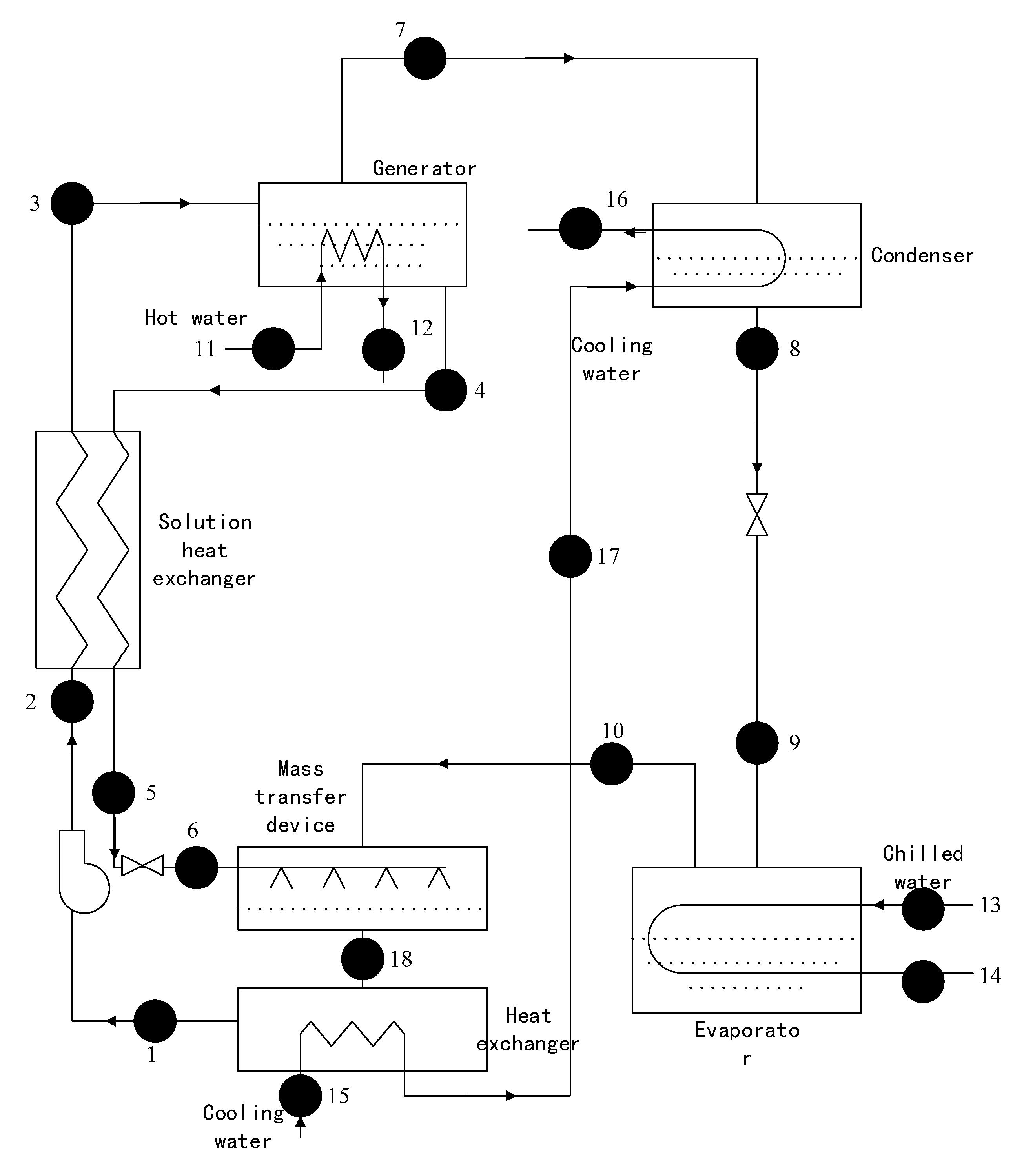
The single-effect Li-Br absorption refrigeration is one of the most popular refrigeration machines in solar cooling due to its low heat source temperature requirement. The single-effect Li-Br absorption refrigeration system can make use of solar energy. Figure 4 shows the flowchart of the single-effect Li-Br absorption refrigeration. Both the main components and the state points on the connecting lines are labeled. The Li-Br absorption refrigeration cycle uses the H2O as the refrigerant and (Li-Br/LiNO3) as the absorbent.

3.3.2. Simulation Model

To simplify the simulation calculation model, some assumptions are used as follows [23]:
(1)
Ignore the pressure drop of fittings and components;
(2)
Ignore the heat loss of fittings and components;
(3)
The absorption pressure pa is equal to the evaporation pressure p0; the generator pressure pg is equal to the condensation pressure pk;
(4)
Both the dilute solution from the absorber and the concentrated solution from the generator are saturated solutions;
(5)
Apply the heat and mass transfer separation model for the solution absorption process;
(6)
Ignore the power consumption of the solution pump.

3.3.3. The Mathematical Model of Each Component

The mathematical models of the absorption refrigeration components are as follows:
(1) Solvent generator
Energy conservation equation:
q g = m 11 C p ( t 11 t 12 ) = m 7 h 7 + m 4 h 4 m 3 h 3
Heat transfer equation:
q g = K g A g Δ t mg
Solute mass conservation equation:
m 3 ξ a = m 4 ξ w = ( m 3 m 7 ) ξ w
The range of vent:
Δ ξ = ξ a ξ w
The circulation rate:
f = m 7 m 3 = ξ w ξ a ξ w
(2) Condenser
Energy conservation equation:
q c = m 16 C p ( t 16 t 17 ) = m 7 h 7 m 9 h 9
Heat transfer equation:
q c = K c A c Δ t mc
(3) Evaporator
Energy conservation equation:
q e = m 13 C p ( t 13 t 14 ) = m 10 h 10 m 9 h 9
Heat transfer equation:
q e = K e A e Δ t me
(4) Solution heat exchanger
Energy conservation equation:
q ex = m 4 h 4 m 5 h 5 = m 3 h 3 m 2 h 2
Heat transfer equation:
q ex = K ex A ex Δ t mex
The heat exchanger efficiency:
ε = t 4 t 5 t 4 t 2
(5) Absorbers
(1) Mass transfer device:
Energy conservation equation:
m 10 h 10 + m 6 h 6 = m 18 h 18
Solute mass conservation:
m 6 ξ a = m 18 ξ w = ( m 3 + m 10 ) ξ w
(2) Heat transfer device:
Energy conservation equation:
q a = m 18 h 18 m 1 h 1 = m 15 C p ( t 17 t 15 )
Heat transfer equation:
q a = K ah A ah Δ t mah
(6) Pump (ignoring the pump power in this paper):
h 1 = h 2
(7) Solution throttle:
h 8 = h 9
Refrigerant throttle:
h 5 = h 6
(8) Heat balance equation:
Considering the calculation error, the unit thermal balance in the simulation results should satisfy the following equation:
| ( q g + q 0 ) ( q k + q a ) | q g + q 0 1 %
(9) Calculation of air temperature drop:
m C p Δ t = Q net · C O P · η
where m is the gas turbine inlet air mass flow; Cp is the specific air heat capacity; Qnet is the working medium heat absorption in the solar collector field; COP is the refrigeration coefficient of the absorption refrigeration system; η is the surface air cooler heat transfer efficiency; and ξ is the solution concentration. Subscript: 1~18 represent the state points in Figure 4.
Table 5 shows that the relative errors between the simulation results and the data in reference from Beiping Jia, Yunxia Qu, Zhaoyue Lv et al. [23] are less than 2%. The simulation results and the design parameter error are within the allowable range, so the model is feasible and reliable. The initial parameters of a single-effect Li-Br absorption refrigeration system are shown in Table 6.

3.4. Performance Evaluation Criteria

Solar power generation (Psolar) is calculated as follows:
P solar = P ISCC P GTCC F fuel ,   ISCC F fuel ,   GTCC
where both PISCC and PGTCC are the power output of the ISCC system and the traditional GTCC system, respectively; both Ffuel,ISCC and Ffuel,GTCC are the fuel consumptions of the ISCC system and the traditional GTCC system, respectively.
Solar photoelectric efficiency (ηsolar) is calculated as follows [24]:
η solar = P solar Q radio
where Qradio is the received solar radiation energy of system, Qradio = Qsolar/ηcol.
Solar photoelectric exergy efficiency (ηf) is calculated as follows [25]:
η f = P solar Q radio ψ
where ψ is the energy grade of solar energy, ψ = 1 − (4/3) × (T0/Ts) + (1/3) × (T04/Ts4); both Ts and T0 are the temperature of the solar surface and ambient, respectively.
Thermal efficiency of the overall system (ηnet) is calculated as follows:
η net = P I S C C Q solar + F fuel ,   ISCC × L H V f × 100 %
where LHVf is the lower heating value of natural gas.
Solar energy contribution of the overall system (Xsolar) is calculated as follows:
X solar = Q solar Q solar + F fuel ,   SCC × L H V f × 100 %
Solar energy LCOE is defined as:
L C O E = L C I N V + L C O & M Δ E annual
where ΔEannual is the annual increment of electricity production of the power plant.
The LCINV is defined as:
L C I N V = C R F I N V = i eff ( 1 + i eff ) n ( 1 + i eff ) n 1 I N V
where CRF is the capital-recovery factor; INV is the total investment; ieff is the effective discount rate, and n is the economic life of the power plant, 15 in this paper.
The LCO&M is defined as:
L C O & M = C 0 O & M C E L F O & M = C 0 O & M k O & M ( 1 k O & M n ) 1 k O & M C R F
k = 1 + r n 1 + i eff
r n = ( 1 + r r ) ( 1 + r i ) 1
where C0 is the cost; CELF is the constant-escalation levelization factor; rn is the nominal escalation rate consists of the real escalation rate rr and average annual inflation rate ri, and k is the parameter. Subscripts: INV and O and M are both the investment and operation and maintenance, respectively.

4. Result Analysis

4.1. Meteorological Parameters

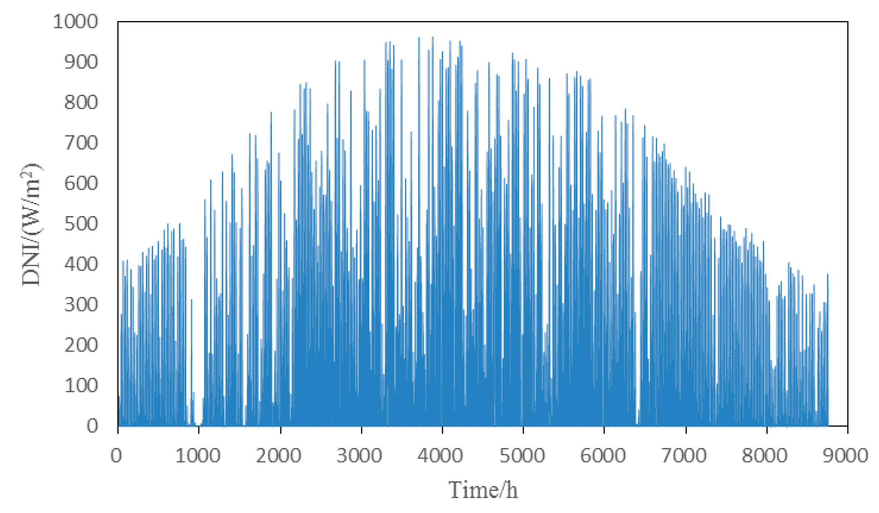
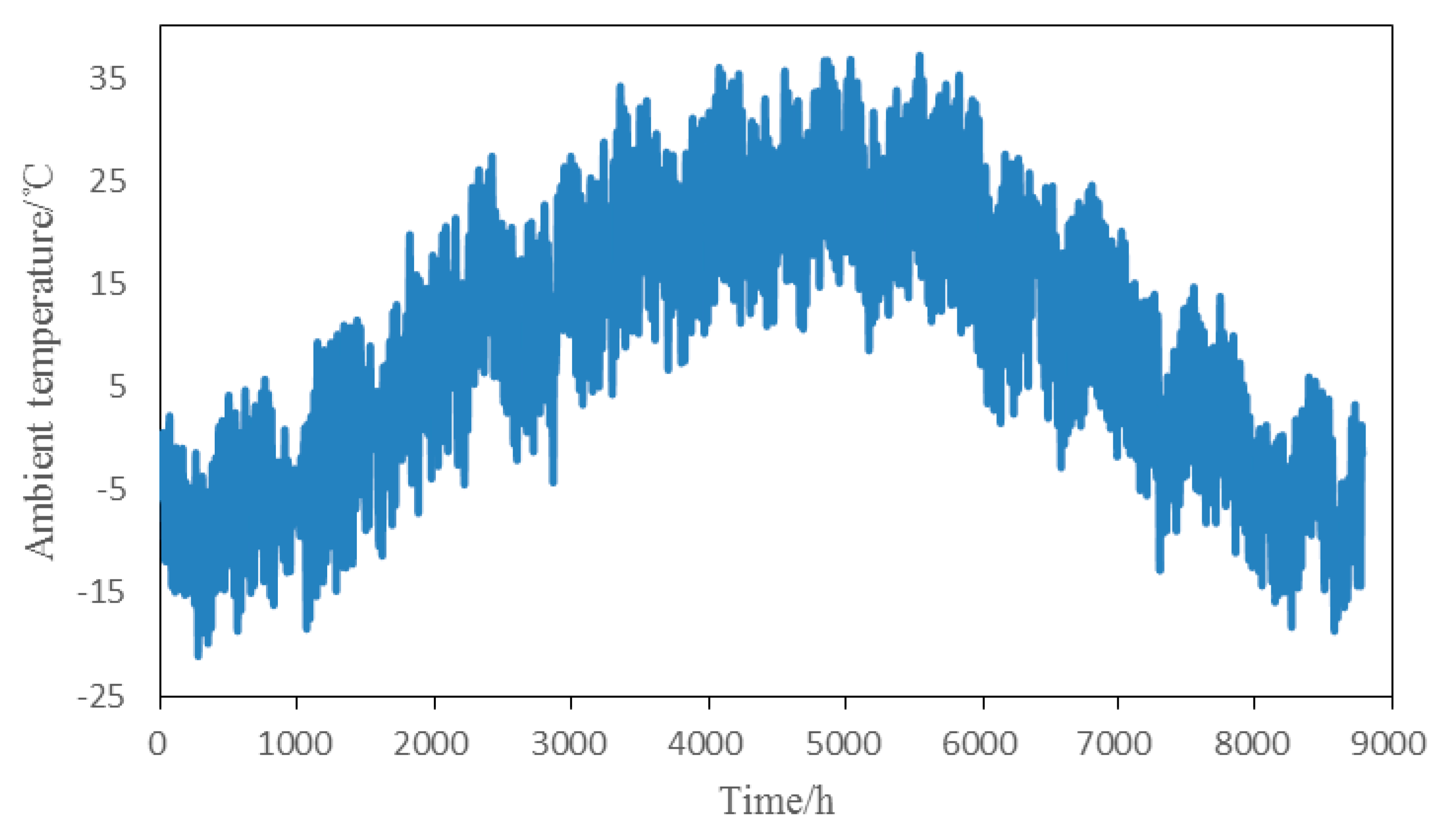
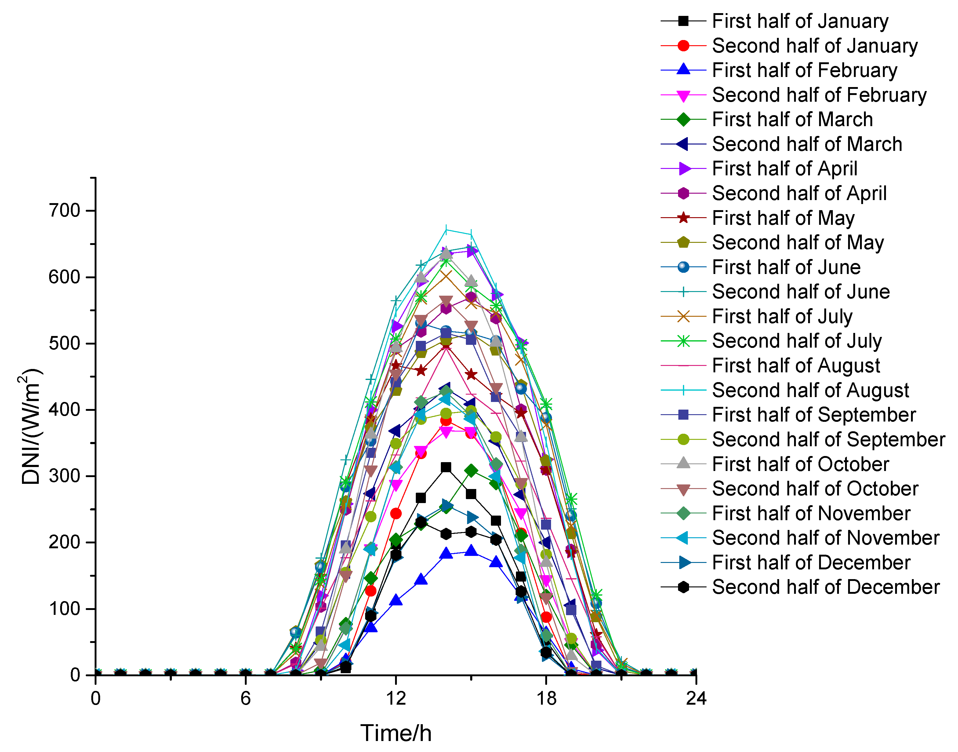
The meteorological data of Dunhuang in this paper from the TRNSYS meteorological database. Figure 5 shows the annual solar radiation. Figure 6 shows the ambient temperature change. Dunhuang with its rich solar energy resource is located at 40.13° N and 94.15° E. The annual climate is relatively dry.

4.2. The Typical Summer Day Performance Calculation

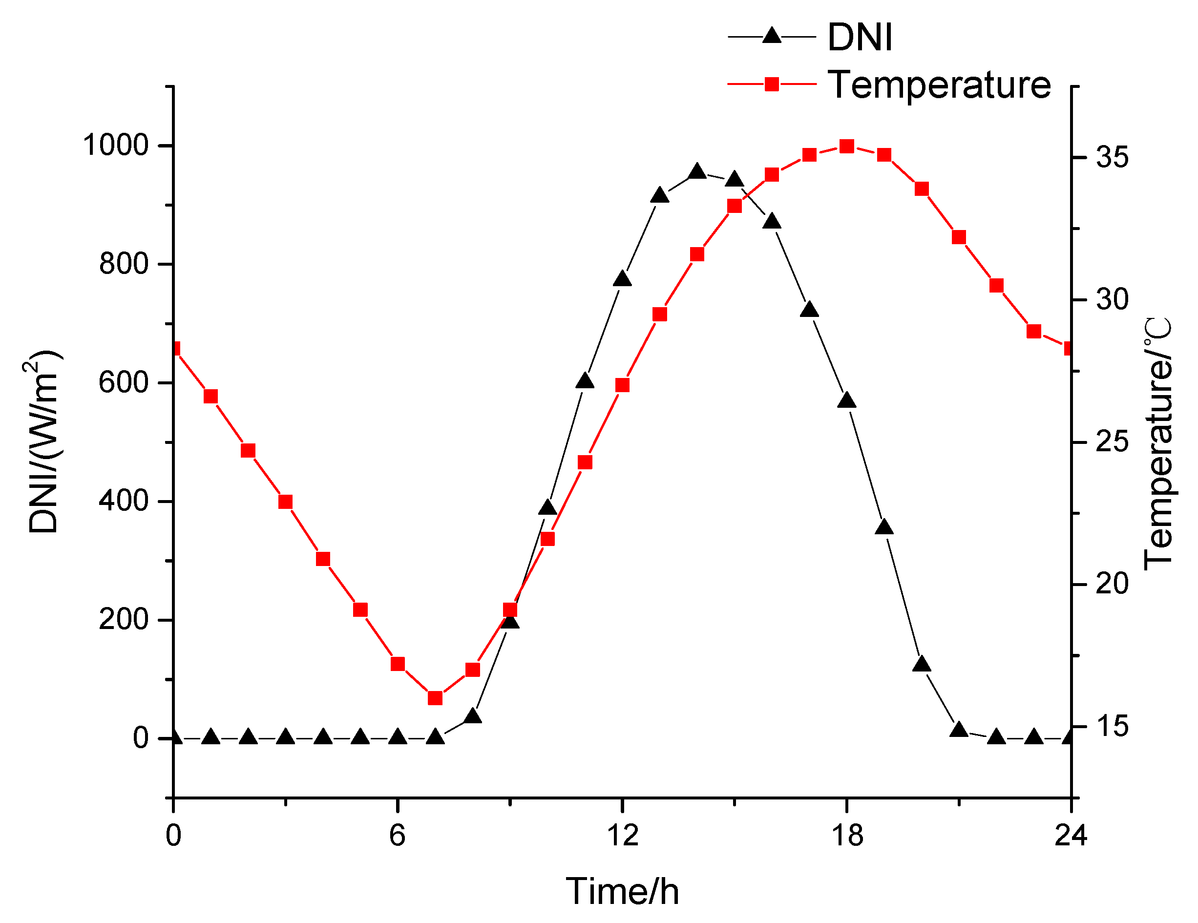
Figure 7 shows the meteorological data for a typical summer day. This research takes five minutes as a time step to simulate a full-day operating performance of both the new ISCC system and the traditional ISCC system with enough consideration of the changes of DNI, meteorological conditions and solar azimuth angle.
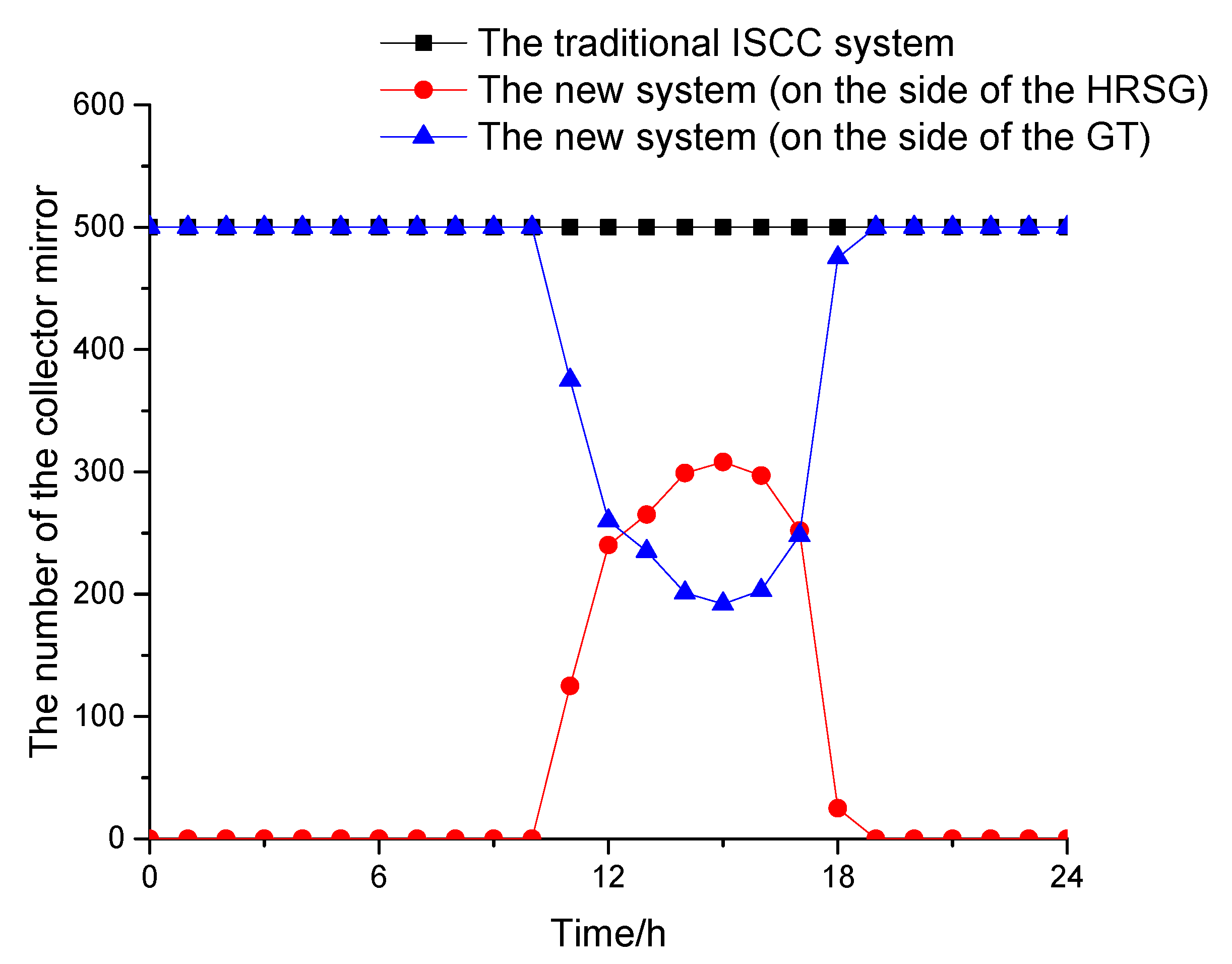
Figure 8 shows the number of the collector mirrors integrated into the side of the HRSG in a typical summer day. As can be seen from the figure, the number of collector mirrors integrated into the HPB of the new system increases at the beginning and then decreases with the change of DNI. With the increase of DNI, the number of the collector mirrors required for the single-effect Li-Br absorption refrigeration unit decreases, the inlet air temperature of the gas turbine compressor can be cooled to the specified temperature by a small number of collector mirrors. Due to that, the total number of the collector mirrors in the solar field is constant, so the number of the collector mirrors integrated into HPB of HRSG will increase.
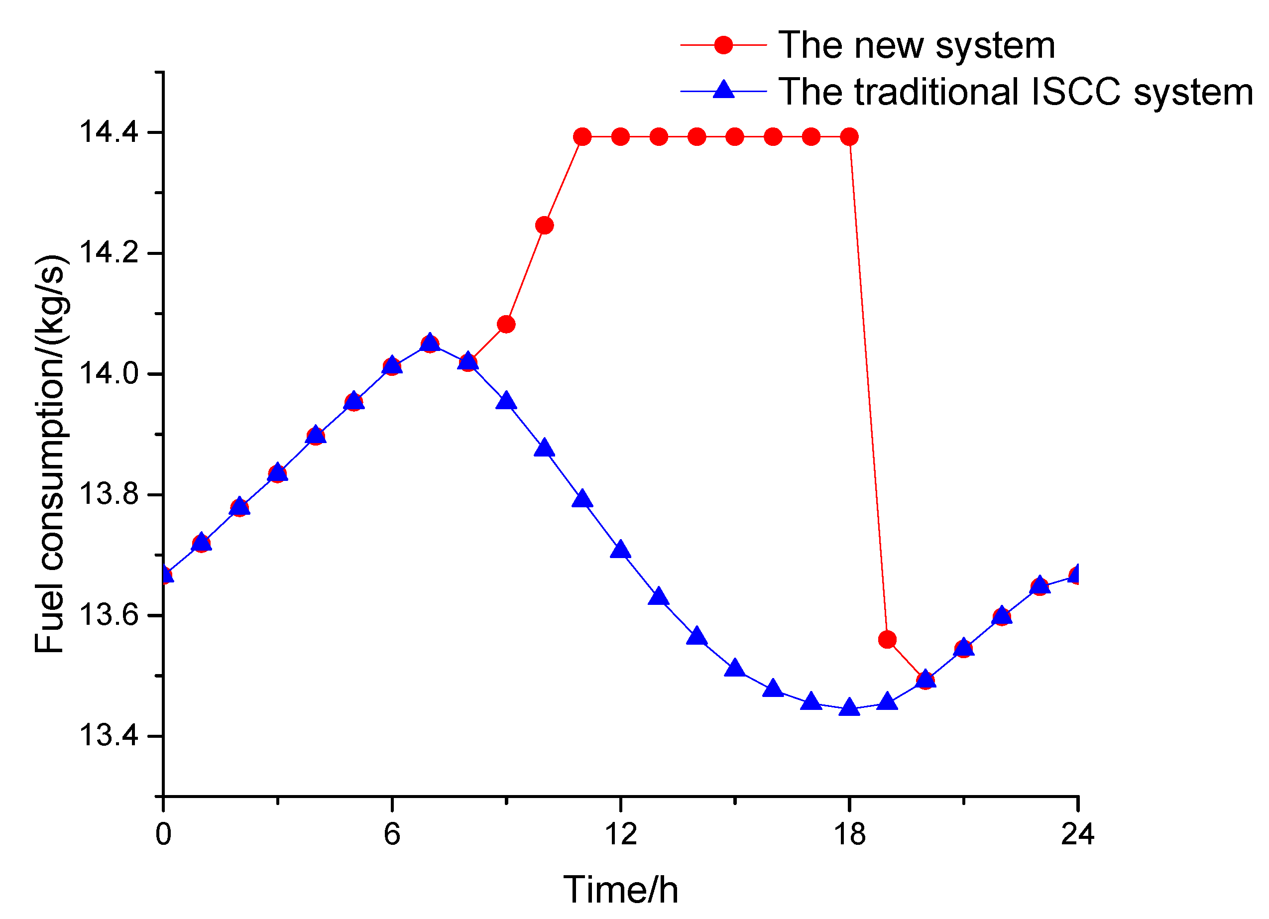
The variation rules of the fuel consumptions of these two systems for the typical summer day are shown in Figure 9. The fuel consumption of the traditional ISCC system decreases as the ambient temperature increases, as shown in Figure 9. The fuel consumption of the new system increases first with the increase of the ambient temperature, then remains unchanged and lastly decreases.
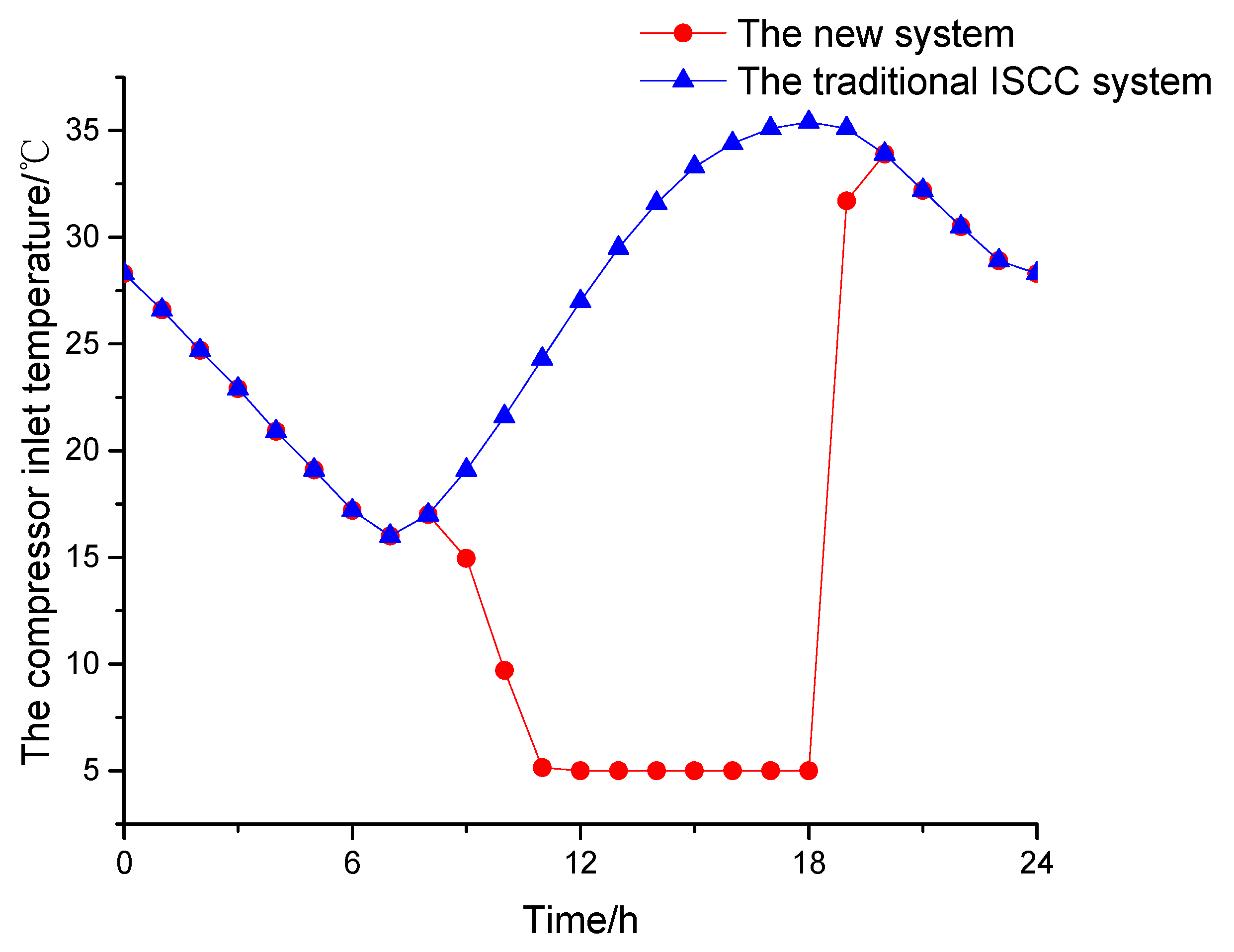
The variation rules of the gas turbine inlet temperatures of these two systems for the typical summer day are shown in Figure 10. The inlet temperature variation trend of the traditional ISCC system is the same as that of the ambient temperature. The inlet temperature of the new system markedly decreases at first, then remains unchanged, and finally increases with the decrease of the ambient temperature. As it is known, the air volume changes with the change of the ambient temperature. When the ambient temperature rises, the specific volume increases and the mass flow decreases, and vice versa. The curves of both Figure 9 and Figure 10 show that when the inlet temperature of the gas turbine drops to 5 °C, the fuel quantity remains unchanged, and the excess solar radiation energy except for the required energy for the gas turbine inlet cooling is integrated into the HPB.
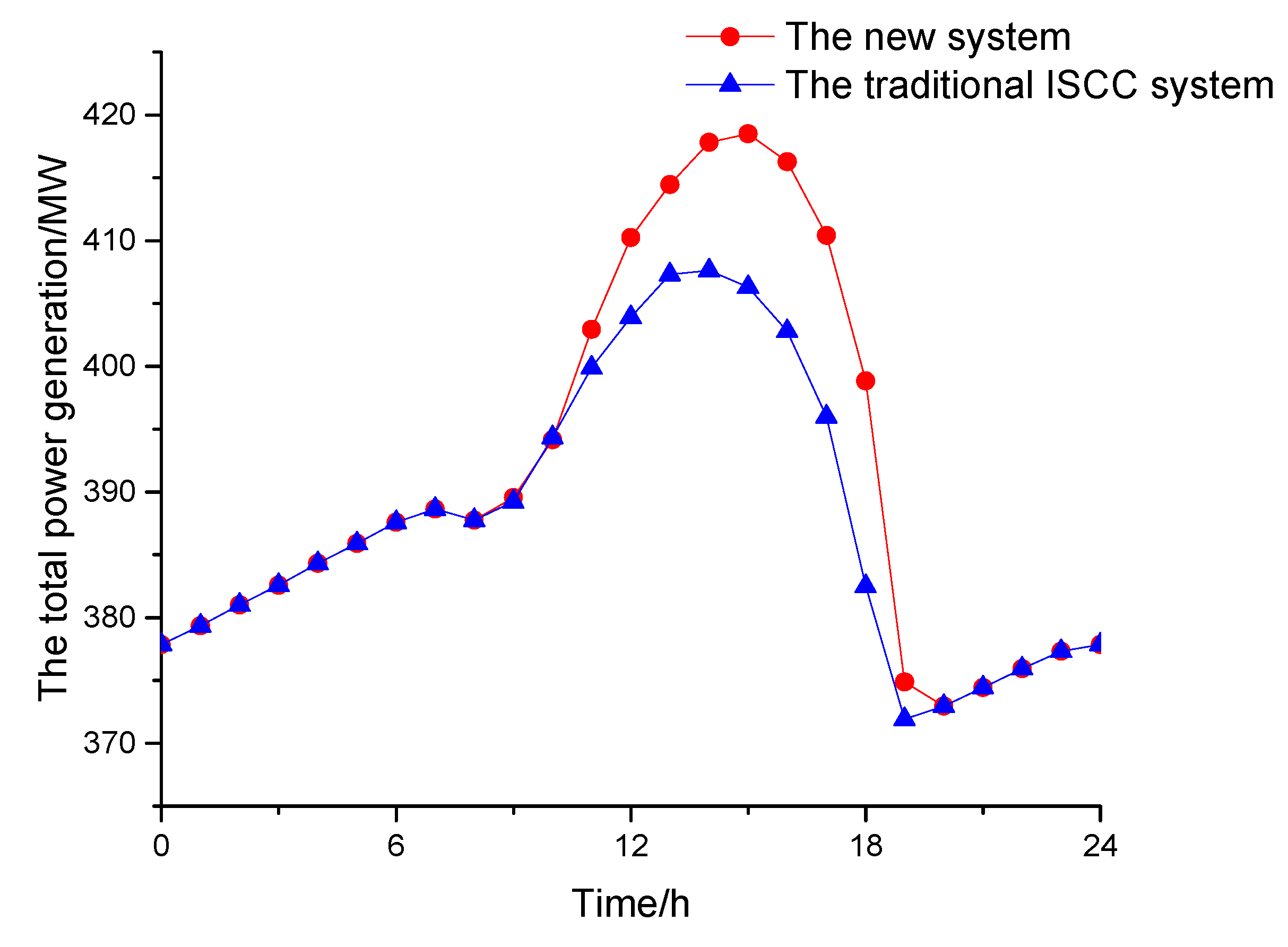
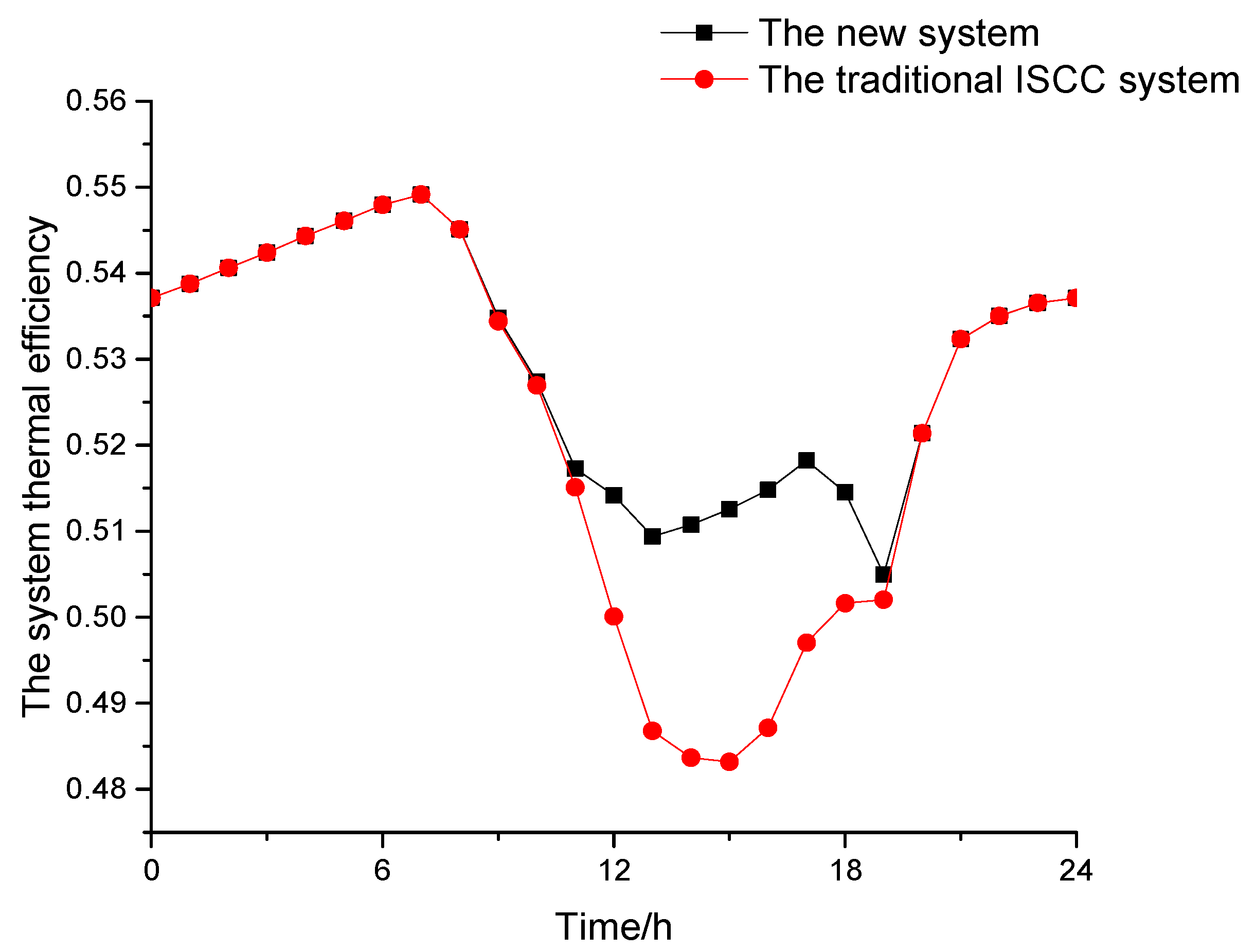
The variation rules of the total power generations of both the new system and traditional ISCC system for the typical summer day are shown in the curves of Figure 11. The variation ranges of the two systems corresponding to the total power generation are 372.96 MW~418.50 MW and 371.92 MW~407.62 MW, respectively. The variation rules of the system thermal efficiencies of both the new system and traditional ISCC system for the typical summer day are shown in Figure 12. The variation ranges of the two systems corresponding to the system thermal efficiency are 50.50%~54.91% and 48.32%~54.91%, respectively. In the case with the solar radiation, the total power generations of both the traditional ISCC system and new ISCC systems are greater than that of the GTCC system. And the new ISCC system has higher total power generation than the traditional ISCC system, and the maximum power generation difference between these two systems is 16.34 MW. There are two main reasons: First, the new system consumes more fuel than the traditional ISCC system as above described; second, the new system has a higher solar thermal efficiency. Figure 12 shows that in the case of with the solar radiation, the system thermal efficiency of the new ISCC system is greater than that of the traditional ISCC system, the maximum system efficiency difference between these two systems is 2.94%. The reason is that the new system preferentially integrates the solar energy into the Li-Br absorption refrigeration system, and the traditional ISCC system integrates all solar energy into the HRSG. Integrating the solar energy into the chiller for cooling the gas turbine inlet temperature has a higher energy conversion efficiency than integrating the solar energy with the HRSG. However, due to the solar thermal energy, density is lower than that of fossil fuels, and the greater the solar thermal energy input is, the lower the system thermal efficiency of the ISCC system is.
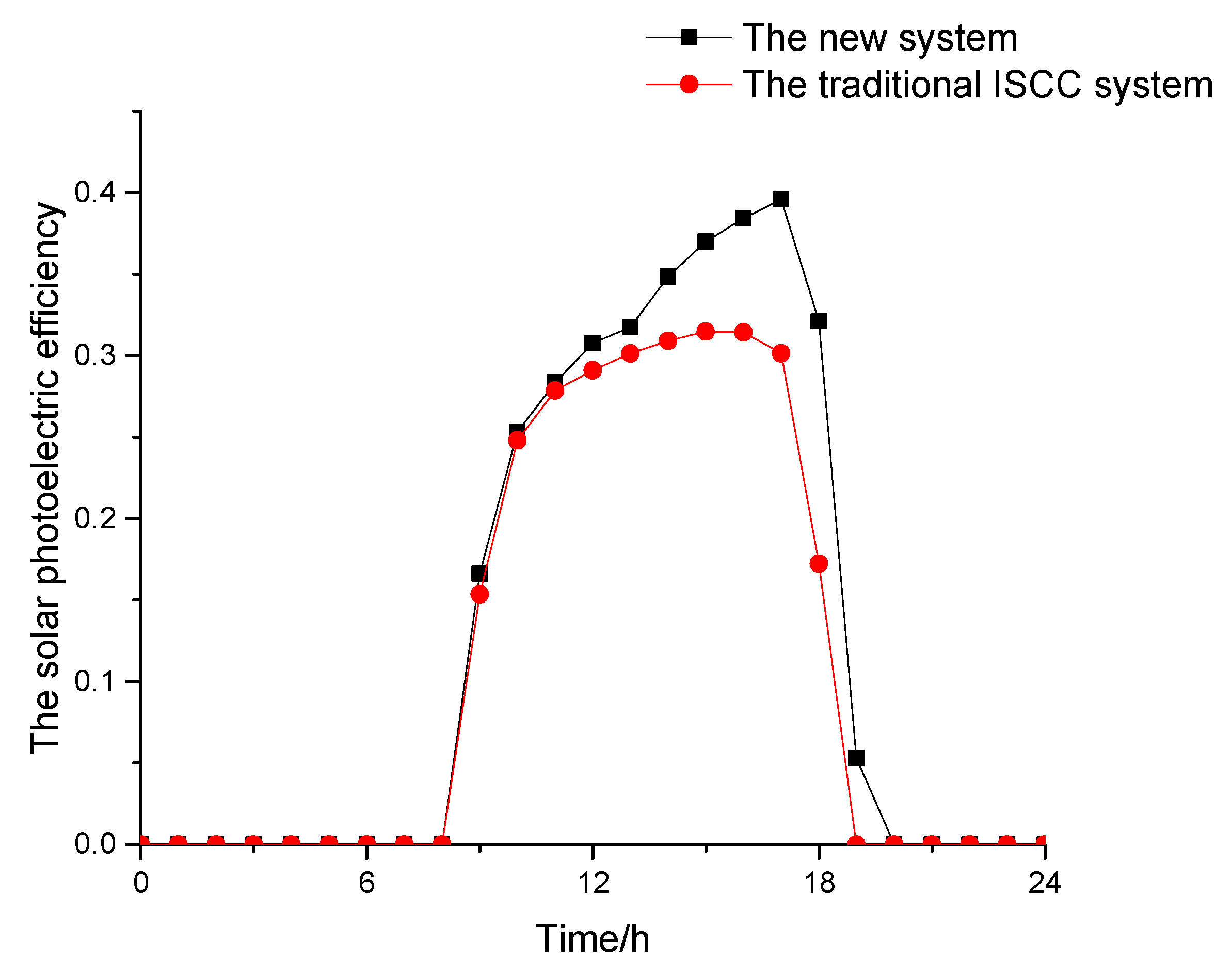
Figure 13 shows the solar photoelectric efficiencies of traditional ISCC system and the new system for the typical summer day. Figure 13 shows that the variation ranges of these two systems corresponding to the solar photoelectric efficiency are 0%~31.49% and 0%~39.60%, respectively. Due to the received solar radiation energy of two systems are the same, and the new ISCC system has higher solar net power generation, according to the Formula (24), the solar photoelectric efficiency of the new ISCC system is obviously higher compared with the traditional ISCC system. The maximum efficiency difference between these two systems is 9.44%. Therefore, under the same solar irradiation condition and mirror field settings, the integration mode of the new ISCC system is superior in thermodynamic performance than the traditional ISCC system. Reducing the inlet air temperature of the compressor will help to improve the solar photoelectric efficiency.
The thermodynamic performances of both the new system and traditional ISCC system during the typical summer day are compared in Table 7.

4.3. The Typical Year Performance Analysis

From the above section, compared with the traditional ISCC system, the new system has better thermodynamic performance. During a year, both the ambient temperature and DNI are constantly changing. The new system’s advantage is that solar energy can be used as much as possible under the same operation condition throughout a year, so it is necessary to adjust the number of the collector mirrors integrated in the side of the HRSG according to different weather data. In Figure 3, both the solar collector field (1) and solar collector field (2) belong to the same big mirror field. The total number of collector mirrors of the two solar collector fields is 500 and remains unchanged.
In addition, this paper takes half a month as a time step to simulate a full-year operating performance for both the new system and traditional ISCC system. The distribution proportions of solar energy integrated in refrigerator and HRSG of the new system are determined in every half a month according to the statistics of the weather data, which will make both the annual solar energy utilization rate and annual solar power generation maximize.
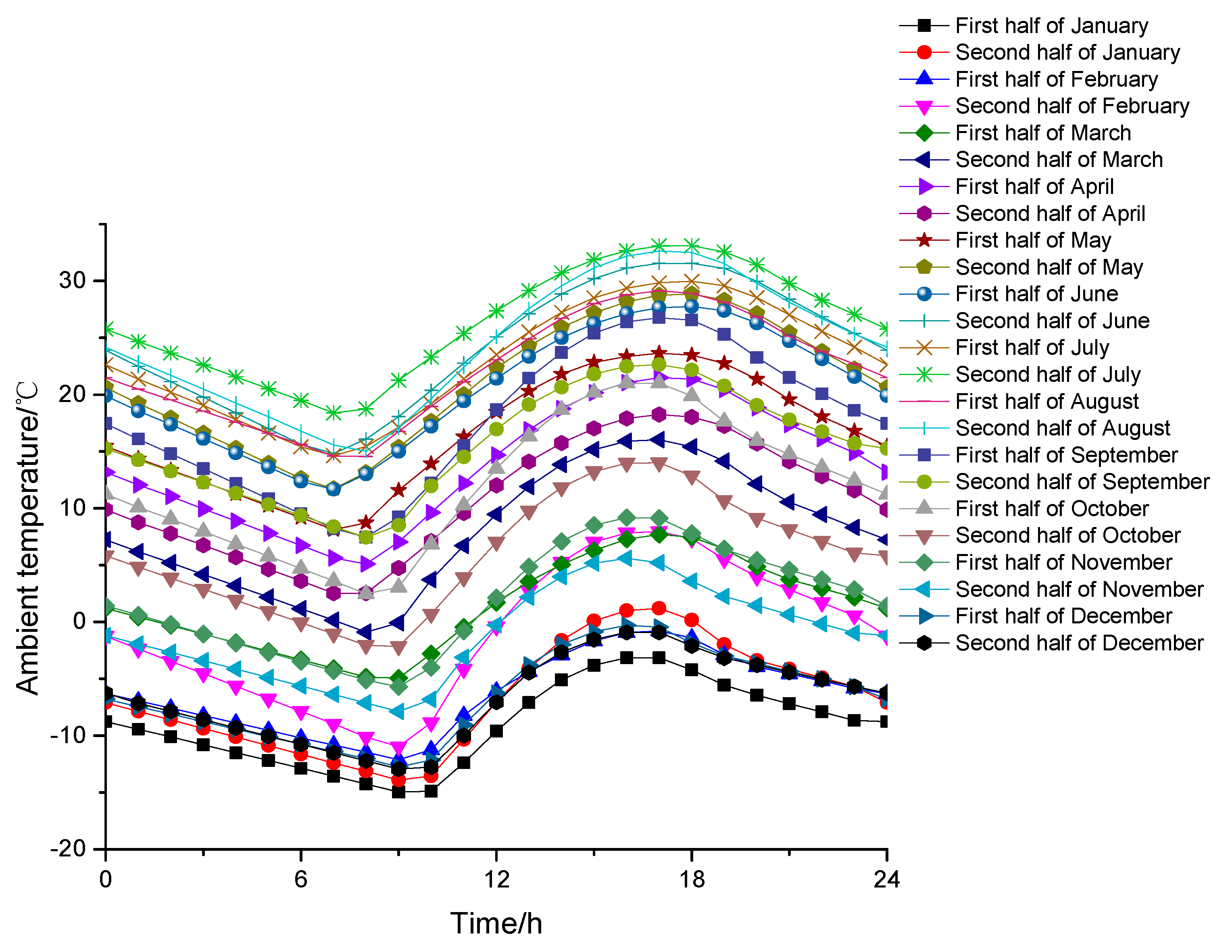
The changes in the average ambient temperature every half a month of the year are shown in Figure 14. The changes in the average DNI every half a month of the year are shown in Figure 15. The ambient temperatures in December, January, and the first half of February are all below 5 °C. During these periods, in consideration of the problem of the surface heat exchanger frosting, ISCC system is not suitable for integrating with the absorption refrigeration, so the total solar field heat is used to integrate with the HRSG.
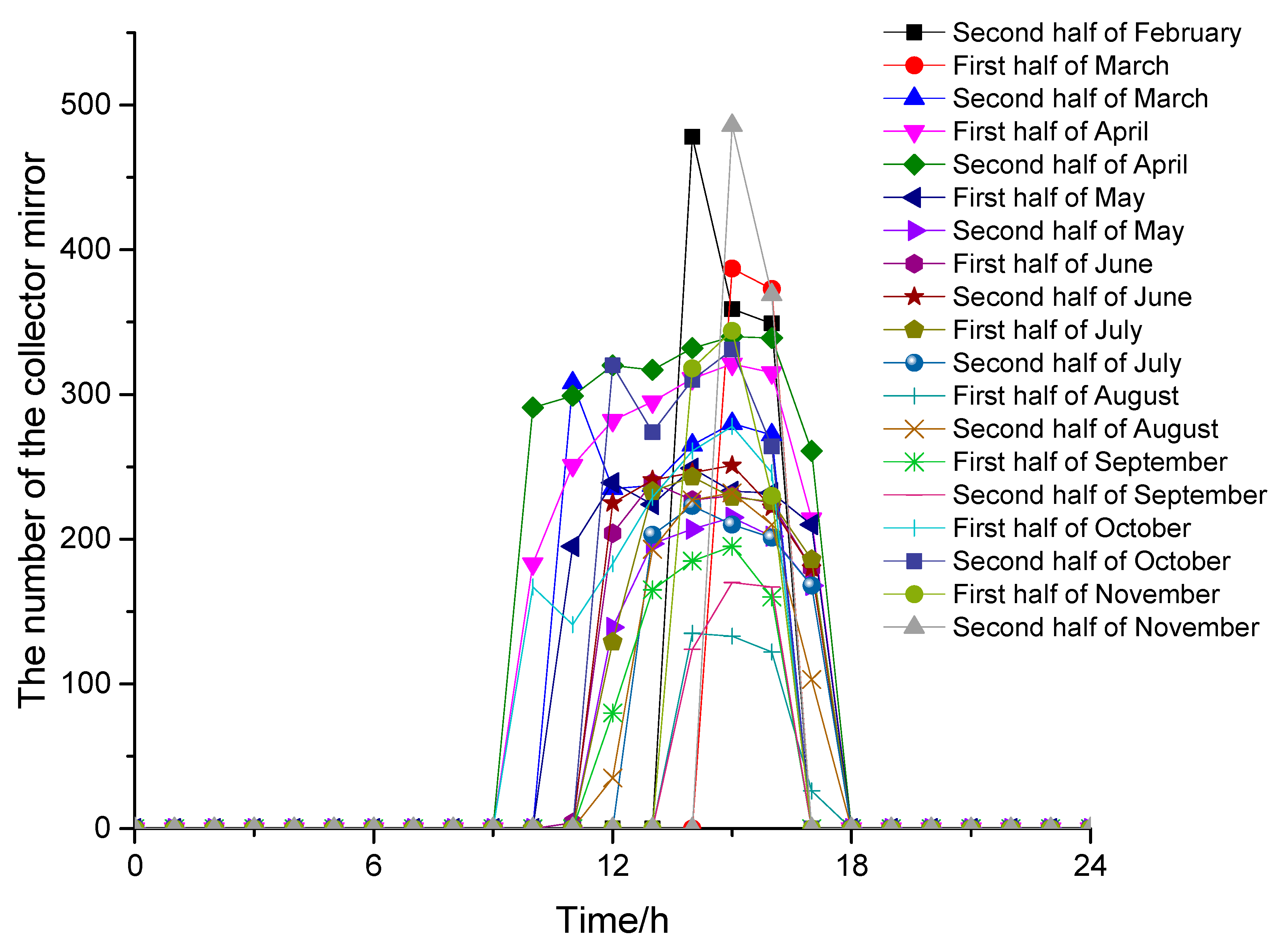
Figure 16 shows the number of the collector mirror integrated in the side of the HRSG in every half a month. It can be seen from Figure 16 that in different months, the number of collector mirrors integrated with HPB of HRSG varies with the changes of both the ambient temperature and DNI. And it can be seen that in spring and summer months with the relatively high DNI, the time of the solar energy integrated into the HPB of HRSG is longer. When the gas turbine inlet temperature reaches the required value, the extra solar energy can be integrated into the HPB of the HRSG at the same time. So, compared with the traditional ISCC system, the new system improves the annual solar energy utilization rate enormously.
Table 8 shows the comparison of thermodynamic performance parameters of the two systems in a typical year. So, cooling the gas turbine inlet air contributes to increasing the system power generation, solar photoelectric efficiency and solar photoelectric exergy efficiency.

4.4. Economic Performance Analysis

The proposed system not only has better thermodynamic advantages but also has better economic performance. To fully compare the solar energy levelized cost of electricity (LCOE) of the new ISCC system and the traditional ISCC system, an economic performance analysis has been done on the base of the equations of [26,27]. The economic assumptions and parameters used in the economic performance analysis are summarized in Table 9.
Table 10 shows the economic performance results. Among them, the LCOE of the new ISCC system is 0.181 $/kW·h, and the LCOE of traditional ISCC system is 0.242 $/kW·h. The solar energy LCOE of the new ISCC system decreased 0.061 $/kW·h compared with that of the traditional ISCC system. The results show that the new ISCC system exhibits economic superiority compared with the traditional ISCC system.

5. Conclusions

The traditional ISCC system operating performance is greatly affected by the meteorological conditions. According to the characteristics of ambient temperature and DNI variation, and at the same time, on the basis of the traditional ISCC system that integrates the solar energy using the DSG system, this paper proposed a novel ISCC system, in which the solar thermal energy is integrated into the chiller for cooling the gas turbine inlet temperature and the HRSG for increasing the system power output simultaneously. Based on the changes in the environmental temperature and DNI, the new system preferentially integrates solar energy into the Li-Br absorption refrigeration system. Compared with the traditional ISCC system, the new ISCC system has better thermodynamic performance and economic performance. The main conclusions are as follows:
(1)
The new system has high solar heat energy utilization, because the benefit of the solar energy integrated with the absorption refrigeration is greater than with the HRSG, so the solar radiation energy preferentially integrates with the Li-Br absorption refrigeration system and then integrates with the HRSG, and the absorption refrigeration can make full use of solar energy;
(2)
The results of the typical summer day of different systems show that the new system has higher system thermal efficiency (52.90%), solar photoelectric efficiency (31.10%), and solar photoelectric exergy efficiency (33.30%) than the traditional ISCC system;
(3)
The results of the typical year of different systems show that the new system has higher system thermal efficiency (57.00%), solar photoelectric efficiency (22.31%), and solar photoelectric exergy efficiency (23.87%) than the traditional ISCC system;
(4)
The solar energy utilization hours of the new system are longer throughout a year, and the solar energy can be used as much as possible, which greatly reduces the average cost of the heat collection mirror;
(5)
The results show that the solar energy LCOE of new ISCC system is 0.181 $/kW·h, 0.061 $/kW·h lower than that of the traditional ISCC system.

Author Contributions

L.D. and Z.W. have worked together in all steps of this paper. They have the same contribution in all the parts of this work.

Funding

This research was funded by the National Nature Science Foundation Project of China, grant number 51576062.

Acknowledgments

This study has been supported by the National Nature Science Foundation Project of China (No. 51576062).

Conflicts of Interest

The authors declare no conflict of interest.

Nomenclatures

Abbreviation
ACAir compressor
CCCombustion chamber
DSGDirect steam generation
DNIDirect normal irradiance
GGenerator
GTCCGas turbine combined cycle
HPHigh pressure
HPBHigh pressure boiler
HPE1High pressure economizer 1
HPE2High pressure economizer 2
HPSHigh pressure super-heater
HRSGHeat recovery steam generator
HTHigh pressure turbine
HTFHeat transfer fluid
IPIntermediate pressure
IPBIntermediate pressure boiler
IPEIntermediate pressure economizer
ITIntermediate pressure turbine
ISCCIntegrated solar combined cycle
LPLow pressure
LPBLow pressure boiler
LPELow pressure economizer
LTLow pressure turbine
RHRe-heater
Symbols
AHeat transfer, m2
C0Cost of the operation and maintenance
cpSpecific heat capacity, kJ/kg·K
CELFConstant escalation levelization factor
COPThe coefficient of performance of absorption refrigeration
CRFCapital recovery factor
fCirculation rate
FMass flow, kg/s
Ffuel,ISCCFuel mass flow of ISCC, kg/s
Ffuel,GTCCFuel mass flow of GTCC, kg/s
ieffEffective discount rate
INVTotal investment
hEnthalpy, kJ/kg
KHeat transfer coefficient, W
LCOELevelized cost of electricity
LCINVLevelized costs of the investment
LCO&MLevelized costs of the operation and maintenance
LHVfLower heating value, kJ/kg
mMass flow, kg/s
nEconomic life, year
qHeat energy, kW
QnetHeat absorption of the working medium in the solar collector field, kJ
QradioSolar radiation energy, MW
QsolarSolar thermal energy, MW
PISCCPower output of ISCC, MW
PGTCCPower output of GTCC, MW
riAverage annual inflation rate
rnNominal escalation rate
rrReal escalation rate
tTemperature, K
ΔtHeat exchange temperature difference
Greek Symbols
ηThe heat transfer efficiency of the surface air cooler
ηsolarSolar thermal efficiency
ηnetSystem thermal efficiency
Δ ξ The range of exhalation
ξ a Dilute solution mass concentration
ξ w Concentrated solution mass concentration
ψSolar energy grade
Subscripts and Superscripts
gGenerator
cCondenser
eEvaporator
ahAbsorber
exExchanger

References

  1. Wang, J.; Lu, Y.; Yang, Y.; Mao, T. Thermodynamic performance analysis and optimization of a solar-assisted combined cooling, heating and power system. Energy 2016, 115, 49–59. [Google Scholar] [CrossRef]
  2. Bellos, E.; Tzivanidis, C.; Moschos, K.; Antonopoulos, K.A. Energetic and financial evaluation of solar assisted heat pump space heating systems. Energy Convers. Manag. 2016, 120, 306–319. [Google Scholar] [CrossRef]
  3. Johansson, T.B. Renewable Energy, Sources for Fuels and Electricity; Island Press: Washington, DC, USA, 1993; Chapter 5; pp. 234–235. [Google Scholar]
  4. Zhu, G.; Neises, T.; Turchi, C.; Bedilion, R. Thermodynamic evaluation of solar integration into a natural gas combined cycle power plant. Renew. Energy 2015, 74, 815–824. [Google Scholar] [CrossRef] [Green Version]
  5. Lewis, N. Toward cost-effective solar energy use. Science 2007, 315, 798–801. [Google Scholar] [CrossRef] [PubMed]
  6. Bianchini, A.; Pellegrini, M.; Saccani, C. Solar steam reforming of natural gas integrated with a gas turbine power plant. Sol. Energy 2013, 96, 46–55. [Google Scholar] [CrossRef]
  7. Behar, O.; Kellaf, A.; Mohamedi, K.; Belhamel, M. Instantaneous performance of the first Integrated Solar Combined Cycle System in Algeria. Energy Procedia 2011, 6, 185–193. [Google Scholar] [CrossRef]
  8. Rovira, A.; Montes, M.J.; Varela, F.; Gil, M. Comparison of Heat Transfer Fluid and Direct Steam Generation technologies for Integrated Solar Combined Cycles. Appl. Therm. Eng. 2013, 52, 264–274. [Google Scholar] [CrossRef]
  9. Montes, M.J.; Rovira, A.; Muñoz, M.; Martínez-Val, J.M. Performance analysis of an Integrated Solar Combined Cycle using Direct Steam Generation in parabolic trough collectors. Appl. Energy 2011, 88, 3228–3238. [Google Scholar] [CrossRef]
  10. Baghernejad, A.; Yaghoubi, M. Exergoeconomic analysis and optimization of Integrated Solar Combined Cycle System (ISCCS) using genetic algorithm. Energy Convers. Manag. 2011, 52, 2193–2203. [Google Scholar] [CrossRef]
  11. Baghernejad, A.; Yaghoubi, M. Exergy analysis of an integrated solar combined cycle system. Renew. Energy 2010, 35, 2157–2164. [Google Scholar] [CrossRef]
  12. Bakos, G.C.; Parsa, D. Technoeconomic assessment of an integrated solar combined cycle power plant in Greece using line-focus parabolic trough collectors. Renew. Energy 2013, 60, 598–603. [Google Scholar] [CrossRef]
  13. Li, Y.; Yang, Y. Thermodynamic analysis of a novel integrated solar combined cycle. Appl. Energy 2014, 122, 133–142. [Google Scholar] [CrossRef]
  14. Li, Y.; Yang, Y. Impacts of solar multiples on the performance of integrated solar combined cycle systems with two direct steam generation fields. Appl. Energy 2015, 160, 673–680. [Google Scholar] [CrossRef] [Green Version]
  15. Manente, G.; Rech, S.; Lazzaretto, A. Optimum choice and placement of concentrating solar power technologies in integrated solar combined cycle systems. Renew. Energy 2016, 96, 172–189. [Google Scholar] [CrossRef]
  16. Popov, D. An option for solar thermal repowering of fossil fuel fired power plants. Sol. Energy 2011, 85, 344–349. [Google Scholar] [CrossRef]
  17. Aboelwafa, O.; Fateen, S.E.K.; Soliman, A.; Ismail, I.M. A review on solar Rankine cycles: Working fluids, applications, and cycle modifications. Renew. Sustain. Energy Rev. 2018, 82, 868–885. [Google Scholar] [CrossRef]
  18. Arrieta, F.R.P.; Lora, E.E.S. Influence of ambient temperature on combined-cycle power-plant performance. Appl. Energy 2005, 80, 261–272. [Google Scholar] [CrossRef]
  19. Patel, B.; Desai, N.B.; Kachhwaha, S.S. Thermo-economic analysis of solar-biomass organic Rankine cycle powered cascaded vapor compression-absorption system. Sol. Energy 2017, 157, 920–933. [Google Scholar] [CrossRef]
  20. Bellos, E.; Tzivanidis, C. Optimization of a Solar-Driven Trigeneration System with Nanofluid-Based Parabolic Trough Collectors. Energies 2017, 10, 848. [Google Scholar] [CrossRef]
  21. Popov, D. Innovative solar augmentation of gas turbine combined cycle plants. Appl. Therm. Eng. 2014, 64, 40–50. [Google Scholar] [CrossRef]
  22. Kesser, K.F.; Hoffman, M.A.; Baughn, J.W. Analysis of a Basic Chemically Recuperated Gas Turbines Power Plant. ASME J. Eng. Gas Turbines Power 1994, 116, 227–284. [Google Scholar] [CrossRef]
  23. Jia, B.P.; Qu, Y.X.; Lv, Z.Y.; Feng, F.S. Simulation Analysis of Solar Li-Br absorption Refrigeration system based on Aspen Plus. Energy Eng. 2014, 30–34. [Google Scholar]
  24. Hong, H.; Jin, H.; Ji, J.; Wang, Z.; Cai, R. Solar thermal power cycle with integration of methanol decomposition and middle-temperature solar thermal energy. Sol. Energy 2005, 78, 49–58. [Google Scholar] [CrossRef]
  25. Petela, R. Exergy analysis of the solar cylindrical-parabolic cooker. Sol. Energy 2005, 79, 221–233. [Google Scholar] [CrossRef]
  26. Nezammahalleh, H.; Farhadi, F.; Tanhaemami, M. Conceptual design and technoeconomic assessment of integrated solar combined cycle system with DSG technology. Sol. Energy 2010, 84, 1696–1705. [Google Scholar] [CrossRef]
  27. Bejan, A.; Tsatsaronis, G.; Moran, M. Thermal Design and Optimization; John Wiley and Sons: Hoboken, NJ, USA, 1996; ISBN 0-471-58467-3. [Google Scholar]
Figure 1. The traditional integrated solar combined cycle (ISCC) system integrated with high pressure boiler (HPB).
Energies 11 03400 g001
Figure 2. Solar-driven single effect Li-Br absorption refrigeration integrated into gas turbine combined cycle (GTCC).
Energies 11 03400 g002
Figure 3. The flowchart of simultaneous integration solar energy into refrigerator and HRSG combined cycle.
Energies 11 03400 g003
Figure 4. Single effect Li-Br absorption refrigeration cycle.
Energies 11 03400 g004
Figure 5. The direct normal irradiance (DNI) data of Dunhuang over a typical year.
Energies 11 03400 g005
Figure 6. The ambient temperature data of Dunhuang over a typical year.
Energies 11 03400 g006
Figure 7. Meteorological data in a typical summer day.
Energies 11 03400 g007
Figure 8. The number of collector mirrors in a typical summer day.
Energies 11 03400 g008
Figure 9. Fuel consumption of the traditional ISCC and the new system in a typical summer day.
Energies 11 03400 g009
Figure 10. Compressor air inlet temperature change of the traditional ISCC and the new system in a typical summer day.
Energies 11 03400 g010
Figure 11. The total power generations of the traditional ISCC and the new system in a typical summer day.
Energies 11 03400 g011
Figure 12. The system thermal efficiencies of the traditional ISCC and the new system in a typical summer day.
Energies 11 03400 g012
Figure 13. Solar photoelectric efficiencies of the traditional ISCC and the new system in a typical summer day.
Energies 11 03400 g013
Figure 14. The changes of average ambient temperature every half a month of the year.
Energies 11 03400 g014
Figure 15. The changes of average DNI every half a month of the year.
Energies 11 03400 g015
Figure 16. The average number of the collector mirror on the side of the HRSG for every half month.
Energies 11 03400 g016
Table 1. The parameters of LS-2 collector.
ParameterValue
Trough mirrorNumber500
Width (m)5
Length (m)47.1
Focal length (m)1.49
Row spacing (m)13
Reflectivity (%)94
Cleanliness (%)95.1
Collector receiverInternal diameter (mm)55
Outer diameter (mm)70
Table 2. The design data of PG9351FA gas turbine.
ParametersValues
CompressorInlet temperature (°C)15
Pressure ratio15.4
Inlet flow (kg/s)621.58
TurbineInlet temperature (°C)1327
Outlet temperature (°C)610
Gas turbineOutput power (MW)255.6
System thermal efficiency (%)36.9
Table 3. Design and simulation data of gas turbine combined cycle (GTCC) system.
ParametersValues
CompressorPressure loss (%)1
Pressure ratio15.4
Isentropic efficiency (%)87
Mechanical efficiency (%)98
CombustorPressure loss (%)3
Gas TurbinePressure loss (%)1
Isentropic efficiency (%)90
Gas TurbineMechanical efficiency (%)98
Inlet air temperature (°C)1327
Exhaust gas temperature (°C)610
Steam TurbineIsentropic efficiency (HP/IP/LP) (%)87.5/89.5/89
HRSGPinch temperature difference (°C)12
Approach temperature difference (°C)8
Hot end temperature difference (°C)45
Exhaust flue gas temperature (°C)86.08
Steam pressure (HP/IP/LP)(MPa)16.5/3.5/0.4
Superheated steam temperature (HP/IP/LP) (°C)565/350/265
Brayton cycleOutput Power (MW)255.6
Thermal efficiency (%)36.90
Rankine cycleOutput Power (MW)132.52
Combined cycleOutput Power (MW)388.12
Thermal efficiency (%)55.27
Table 4. Comparison of thermodynamic calculation results of the GTCC system.
ParameterValue (Design)Value (Simulation)
Compressor inlet flow (kg/s)621.58621.58
Compressor pressure ratio15.415.4
Gas turbine inlet air temperature (°C)13271327
Gas Turbine exhaust gas temperature (°C)610609.5
Gas Turbine exhaust flow (kg/s)635.66635.88
Superheated steam temperature (HP/IP/LP) (°C)565/350/265565/350/265
Superheated steam flow (HP/IP/LP) (kg/s)73.02/10.97/17.0172.89/11.08/16.94
HRSG exhaust flue gas temperature (°C)86.0885.84
Gas turbine output power (MW)255.6254.14
Steam turbine output power (MW)132.52133.11
Gas turbine cycle efficiency (%)36.9036.69
Combined cycle efficiency (%)55.2755.67
Table 5. Comparison of thermodynamic calculation results of the refrigeration system.
ParameterValue (Reference)Value (Simulation)
Dilute solution flow (kg/s)1010
Dilute solution pressure (kPa)9.69.6
Concentrated solution (kg/s)9.39.29
Concentrated solution pressure (kPa)9.69.6
Chilled water flow (kg/s)75.875.83
Generator load (kW)26.5926.81
Absorber load (kW)25.5325.73
Condenser load (kW)21.2421.64
Solution heat exchanger load (kW)7.27.3
COP0.750.75
Table 6. Initial specification parameters for simulation operation.
Single Effect Li-Br Absorption Refrigeration ModelValues
Solar heat source water supply temperature (°C)118.6
Cooling water inlet temperature (°C)30
Dilute solution flow (kg/s)10
Dilute solution mass fraction (LiBr/LiNO3) before solution pump (%)59.5
LiBr/LiNO3 molar ratio4:1
Evaporation temperature (°C)5
Condensation temperature (°C)40
Deflated range (%)4.5
Temperature difference between heat flow outlet and cold flow inlet of solution heat exchanger (°C)15
Table 7. Thermodynamic performance parameters for a typical summer day.
The New SystemThe Traditional ISCC System
Total power generation (MW·h)9.211 × 1049.031 × 104
Solar net power generation (MW·h)256.355133.53
Solar energy contribution (%)6.323.62
Solar photoelectric efficiency (%)31.124.4
Solar photoelectric exergy efficiency (%)33.3026.12
System thermal efficiency (%)52.952.2
Table 8. Annual thermal performance data.
The New SystemThe Traditional ISCC Systems
Total power generation (MW·h)3.38 × 1063.36 × 106
System thermal efficiency (%)57.0056.84
Solar photoelectric efficiency (%)22.3116.67
Solar photoelectric exergy efficiency (%)23.8717.83
Table 9. Cost assumption data used for the economic analysis.
InvestmentValueFinancial ParametersValue
Specific investment cost for solar field ($/m2)206.8ieff (%)10
Specific land cost ($/m2)2.03n (years)15
Specific Li-Br fluid cost ($/kg)2.03ri (%)3
Surcharge for construction, engineering and contingencies (%)10rr (%)1
Specific Li-Br absorption refrigerator cost ($/kW) 13
Operation and Maintenance
Solar field specific O and M costs ($/m2·year)9.26O and M equipment cost percentage of investment per year (%)1
Table 10. The solar energy levelized cost of electricity (LCOE) of different systems.
ParametersValue
LCOE ($/kW·h) of the traditional ISCC system0.242
LCOE ($/kW·h) of the new system0.181