Article

Method for the Energy Storage Configuration of Wind Power Plants with Energy Storage Systems used for Black-Start

1
Electrical Engineering College, Northeast Electric Power University, Jilin 13012, China
2
Key Laboratory of Modern Power System Simulation and Control & Renewable Energy Technology, Ministry of Education (Northeast Electric Power University), Jilin 132012, China
3
NARI Technology Development Limited Company, Jiangsu Province, Nanjing 210061, China
4
Hohhot Power Supply Bureau, State Grid Inner Mongolia Electric Power Company Limited, Hohhot 010020, China
*
Author to whom correspondence should be addressed.
Energies 2018, 11(12), 3394; https://doi.org/10.3390/en11123394
Submission received: 19 October 2018 / Revised: 17 November 2018 / Accepted: 29 November 2018 / Published: 4 December 2018
(This article belongs to the Section D: Energy Storage and Application)

Abstract

:
With the increasing participation of wind generation in the power system, a wind power plant (WPP) with an energy storage system (ESS) has become one of the options available for a black-start power source. In this article, a method for the energy storage configuration used for black-start is proposed. First, the energy storage capacity for starting a single turbine was determined. Then, a hierarchical planning model was established. This model did not consider the starting efficiency of the WPP, but it did consider the layout of the energy storage in the WPP and the balance of the terminal voltage when starting the WPP. Finally, the feasibility and value of the proposed method and model were verified in a 49.5 MW WPP with an ESS (a power rating of 2.24 MW and energy capacity of about 1.68 MWh). The result suggests that configuring an ESS with a small capacity on the side of the turbine can achieve black-start for a WPP with an ESS as the power source.

1. Introduction

While power systems benefit greatly from large-scale interconnections [1], they have the potential for a risk of blackout due to natural disasters, equipment failures, maloperation, and grid-connected renewable energy sources [2,3]. Recently, several large-area blackouts (causing serious social impacts and economic losses) have occurred all over the world, such as the blackout in Taiwan, China on 15 August 1999, the blackout in the USA and Canada on 14 August 2003, and the blackout in Brazil on 21 August 2018 [4,5]. Black-start, the procedure to restore a power system by self-starting black-start units, is the most important task after a large-area blackout [6]. So, a black-start strategy that starts multiple self-starting power sources at the same time can improve the recovery efficiency of power grid. To this point, the key technology of black-start [7], the subsystem partitioning based on self-starting power [8], and the optimization of the network framework reconfiguration around the recovery sequence of wind turbines [9,10] have been studied to various degrees.
The traditional black-start power supply (thermal power, nuclear power and hydropower) gives priority to hydropower, which has advantages of less auxiliary power consumption and high starting speed. Although wind power and other renewable energy sources have small starting power and high starting speed, they are seldom considered as black-start power because of their unstable output, which brings the grid-connected renewable energy sources problems [11]. With regard to the grid-connected renewable energy sources, various algorithms have been studied; such as a control technique based on inherent characteristics of synchronous generators for control of interfaced converters with high penetration of renewable energy resources into the power grid [12], a novel COS simulation framework for regional power systems with high penetration of renewable energies using meteorological data, which consists of the following three steps: data preparation, modeling and solving, and result output [13], a synchronous resonant control strategy based on the inherent characteristics of permanent magnet synchronous generators for the control of power converters to provide stable operating conditions for the power grid under high penetration of renewable energy resources [14], a control model based on direct Lyapunov control theory for integration of distributed generation sources into the power grid [15], a comprehensive dynamic model based on Direct-Quadrature rotating frame which is used along with a capability curve based on the active and reactive power to control a grid-connected single-phase voltage source inverter [16].
With the increasing participation of wind power in the power system, the possibility of wind power participating in black-start is gradually increasing. Especially those that lack traditional black-start power sources, if wind power can participate in black-start smoothly, it will greatly accelerate the process of black-start [6].
Energy storage technology can respond flexibly to power at different time scales. With the advance of wind storage technology, the output voltage and power of a WPP are more stable [17]. Due to the low power density characteristics of wind energy and the fact that wind turbines are under light load for most time, the doubly fed induction generator (DFIG) are used to take part in reactive power regulation [18,19].
Several studies have been reported in the literature with respect to wind power plants with energy storage systems as the black-start resources [20,21,22,23,24,25,26,27,28,29]. Based on the special geographical position of the local power network in Jiangsu China, the literature [20] analyzes the feasibility of a WPP with diesel engine used as a black-start power source. Then literature [21] discussed the feasibility of a WPP with an ESS as a power source for black-start, in which the Daliang wind farm is used as the black-start resource with high-capacity BESS configured. Furthermore, in the black-start system, various publications [22,23] have designed and simulated the strategy of automatic power balance control and voltage control for a converter station based on the renewable energy respectively. Moreover, the energy storage capacity of a WPP with an ESS is proposed in [24], which configure the storage power station based on maximum power fluctuation of initial restoration system at WPP access point. Additionally, the related literatures have studied the key technologies of the charging control strategy of transformer [25], the charge and discharge characteristic of an ESS [26], the cooperative frequency control [27,28], the optimal configuration of energy storage [29], the reactive voltage control [30,31], the optimal allocation of output transmission capacity and energy storage capacity of WPP [32,33], and the specific battery modeling technology [34].
Research on the auxiliary participation of a WPP with an ESS in black-start, in the above literature, is based on an ideal large-capacity energy storage power station. For a WPP with an ESS as the direct starting power, the allocation method of energy storage does not have pertinent research. Research on the energy storage configuration is mainly on configuring the energy storage system at the bus-connected outlet of the WPP, or on building large-scale storage power stations at the station of grid-connected renewable energy sources, which is the redevelopment and utilization of the function of an energy storage power station. Moreover, as a WPP with an ESS-applied black-start is not economical enough to allocate a large-capacity energy storage power station, it is necessary to optimize the energy storage configuration.
A method of configuring an ESS with small capacity on the side of the turbine is proposed, which can achieve black-start for a WPP with small energy storage cabinets as the power source. In this method, reducing the costly cost of building large-scale energy storage power stations and solving the problem of wind power being used as black-start sources is achievable.
Based on the analysis of the energy storage configuration and the black-start process of a WPP with an ESS, an energy storage configuration model is established. This model not only contains the energy storage capacity configuration and the optimization of an energy storage layout, but it also considers the starting sequence of turbines that are influenced by the reactive power variation.
The remains of this paper are as follows: The black-start progress and the traditional energy storage configuration are introduced in Section 2. The method for energy storage configuration based on the hierarchical planning model are given in Section 3. The hierarchical planning model of the energy storage configuration is shown in Section 4. Case simulations and further discussion is implemented in Section 5. Finally, some conclusions are offered in Section 6.

2. WPP with ESS in Black-Start

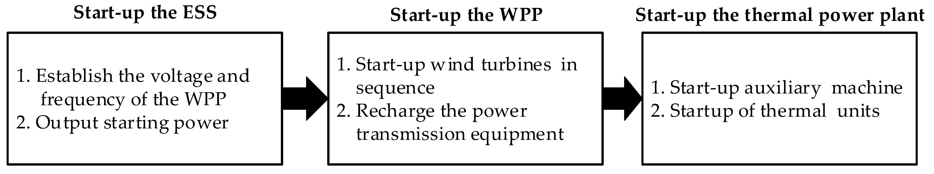
2.1. The Process of Black-Start

After getting the command to match the black-start, the WPP first uses its own power source to realize the operation of the plant control system; second, to control the self-starting of the ESS; third, to establish the bus voltage of the plant and to restore the electricity of the plant and turbine; and finally, to complete the start-up of the wind turbine. Since then, the WPP with ESS as the initial power completes the recovery of the subsequent network frame and load.
The black-start process and specific wiring diagram of the network, based on the WPP with ESS, are shown in Figure 1 and Figure 2 separately.
When the WPP with ESS is used as the starting power for black-start, in a full black state, the voltage and frequency of the starting wind turbine and the electrical energy of the self-system will all originate in the ESS.

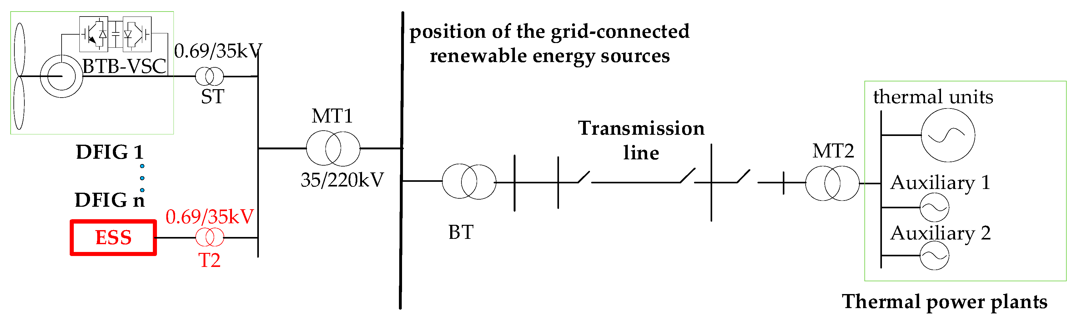
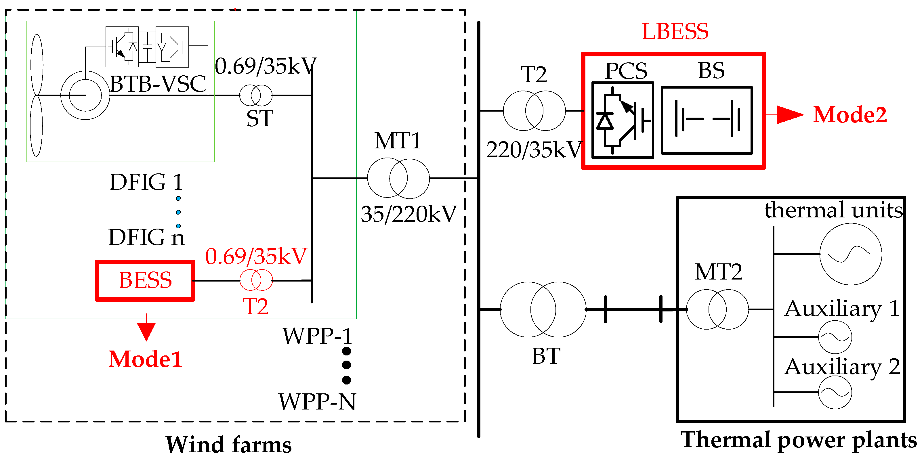
2.2. The Configuration Mode of Energy Storage

As shown in Figure 3, there are two ways to study the energy storage configuration of WPP participating in black-start.
Mode 1 of the energy storage configuration: the ESS is equipped in the position of the bus-connected outlet of the WPP. It is meant to stabilize the total output power and voltage fluctuation of the WPP, and reduce the influence of wind power integration on the stability of the network, and the power quality.
Mode 2 of the energy storage configuration: the ESS is established in the position of the grid-connected renewable energy sources. This large energy storage power station has many functions: smooth output, plan tracking, automatic generation control, frequency modulation, peak load shifting, and so on.
The above two models redevelop and reuse the power station, but there are still some disadvantages when these modes are applied to black-start.
  • When starting the wind turbine, multiple voltage conversions are needed. Three voltage conversions are required simultaneously in mode 2, which causes operational problems.
  • The energy storage power station is multi-tasked and cannot ensure the reliability of the black-start. For example, the residual energy of the system that is involved in peak shaving cannot meet the demand from the wind turbines.
  • In the black start, the energy storage capacity has not been determined. Each wind farm has its own energy storage demand in the black start, and there is no clear demand for energy storage. However, it is relatively easy to build energy storage power stations at the position of the grid-connected renewable energy sources, which are mainly used to stabilize renewable energy sources fluctuations. Moreover, considering the high cost of energy storage power station construction, it will create a situation, which is a demonstration project that has already been built in mode 2, but it is still being researched in mode 1.

3. Method for the Energy Storage Configuration Based on the Hierarchical Planning Model

For the condition of a WPP with an ESS as the black-start power source, the capacity and layout of the energy storage, and the reactive power distribution should be taken into consideration in order to obtain the whole energy storage configuration method. In the above method, the energy storage with a small capacity can start the entire WPP.

3.1. Energy Storage Capacity and Configuration, and the Starting Efficiency Analysis of the WPP

As shown in Figure 3, the ESS is installed on the low voltage side of the boost transformer by means of a small capacity storage cabinet. The energy storage cabinet is used as a stand-by heat power supply to establish the reference information of the grid during the black start, and provide the plant demand for a turbine, in order to assist with starting the turbines. Subsequently, the turbines with energy storage are used as the initial power to start the other turbines in turn, and to complete the start-up of the WPP.
On these grounds, a starting efficiency model based on the starting power of a single wind turbine is established.
With some assumptions: (1) the wind speed does not change in the span of one minute; (2) the turbine is continuously rotating; and (3) the starting time and capacity of each turbine are identical, the relationship between the output power Pw of the turbine and the number of starting turbines, n, at the same time can be obtained from the following formula:
P w = 1 2 π R 2 ρ V m 3 C p
P w P Z α 1 n P Z - I m + 1 n P Z - R > n     ( n N * )
where R is the radius of the wind wheel, ρ is the air density, and Vm is the average wind speed of the initially starting turbine that takes the average wind speed within the maximum load period of the power grid. PZ is the power of the plant demand for the starting turbine demand, PZ-Im and PZ-R are the power of the asynchronous motor and the other equipment, respectively, and PZ = PZ-Im + PZ-R is the power for same-type turbines. Cp is the wind energy utilization coefficient, taking the wake effect into account, which is 0.48, α is the capacity margin used by the small power generator to start the asynchronous motor of the small power directly, and according to the code for the design of the distribution system in GB50052-2009, α is taken as 6.5.
The increasing relationship between the number of turbines, x, the initially equipped energy storage, and the number of starting turbines, n, can be given by:
x ( n + 1 ) k > N
where k is the starting batch, and N is the number of turbines.
The starting-time constraint Tall of the WPP can be expressed as:
( k + 1 ) t f T a l l
where tf is the total time length of the wind turbine from the starting turbine to stable output, Tall is the starting constraint time of the WPP, referencing the black-start test data of the hydroelectric unit from the start to the stable output [35], and Tall is taken as 240 s.

3.2. Configuration and Layout of the Energy Storage

The spatial and temporal differences of wind energy distribution lead to a decentralized operation state of wind turbines in large scale WPPs. In a heavy load period (with a pressure drop caused by the cooling demand in 7~9 months), the layout of the energy storage is optimized by analyzing the distribution of the wind energy in the WPP.
The design of the energy storage configuration should take into account the elements that follow.
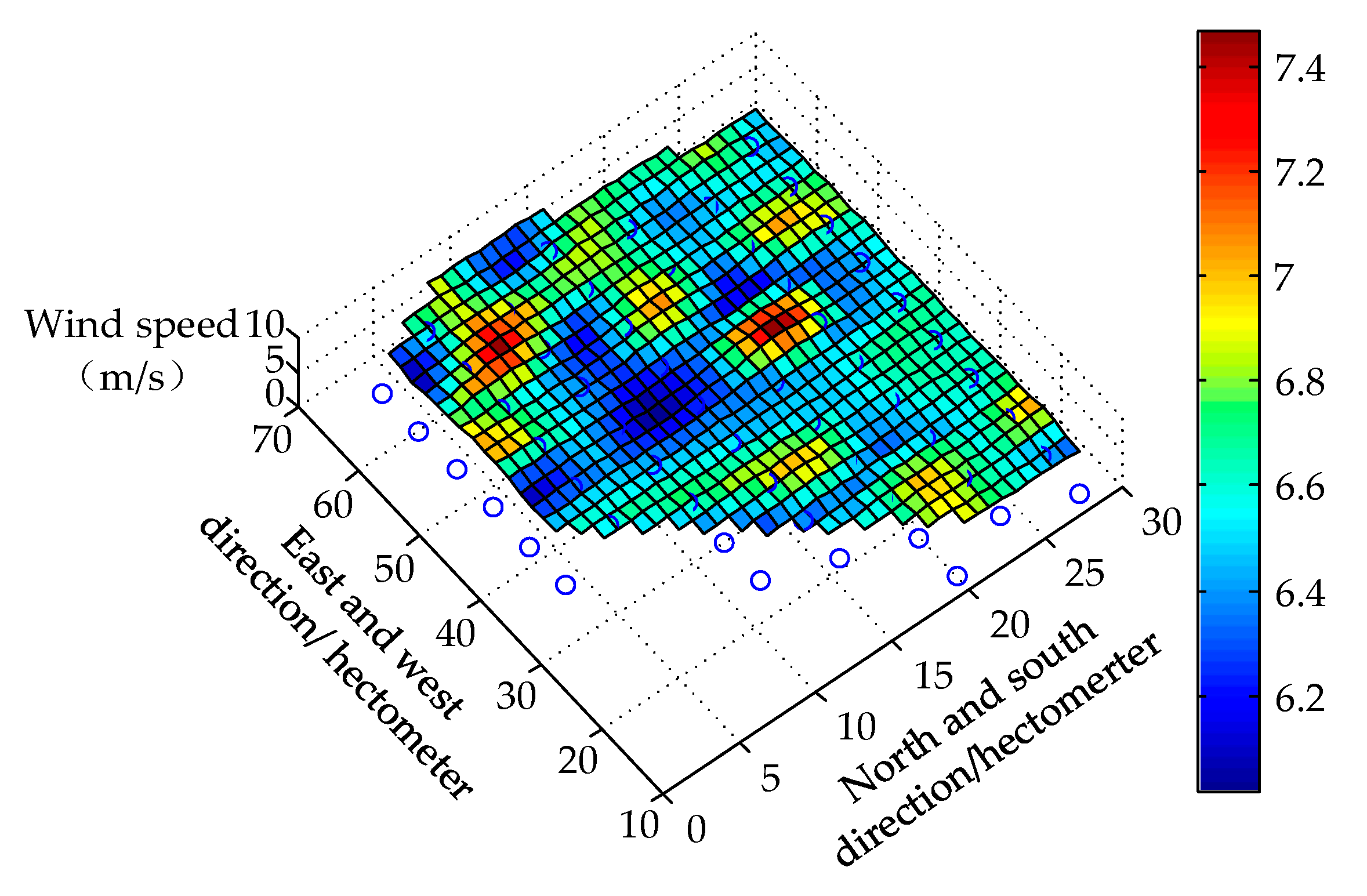
  • Considering the position of the turbine in the WPP, the wake effect leads to a difference in the wind energy distribution.
  • Excluding dispatching, the historical output duration of the turbine reflects the “health” situation of the turbines.
  • The matching degree between the historical wind speed and the historical output of the turbine reflects the comprehensive utilization efficiency of the wind speed for the turbines.
In order to complete the configuration and layout of the energy storage, the wind turbines are classified, and the turbines with energy storage are selected according to their “excellent” degree.

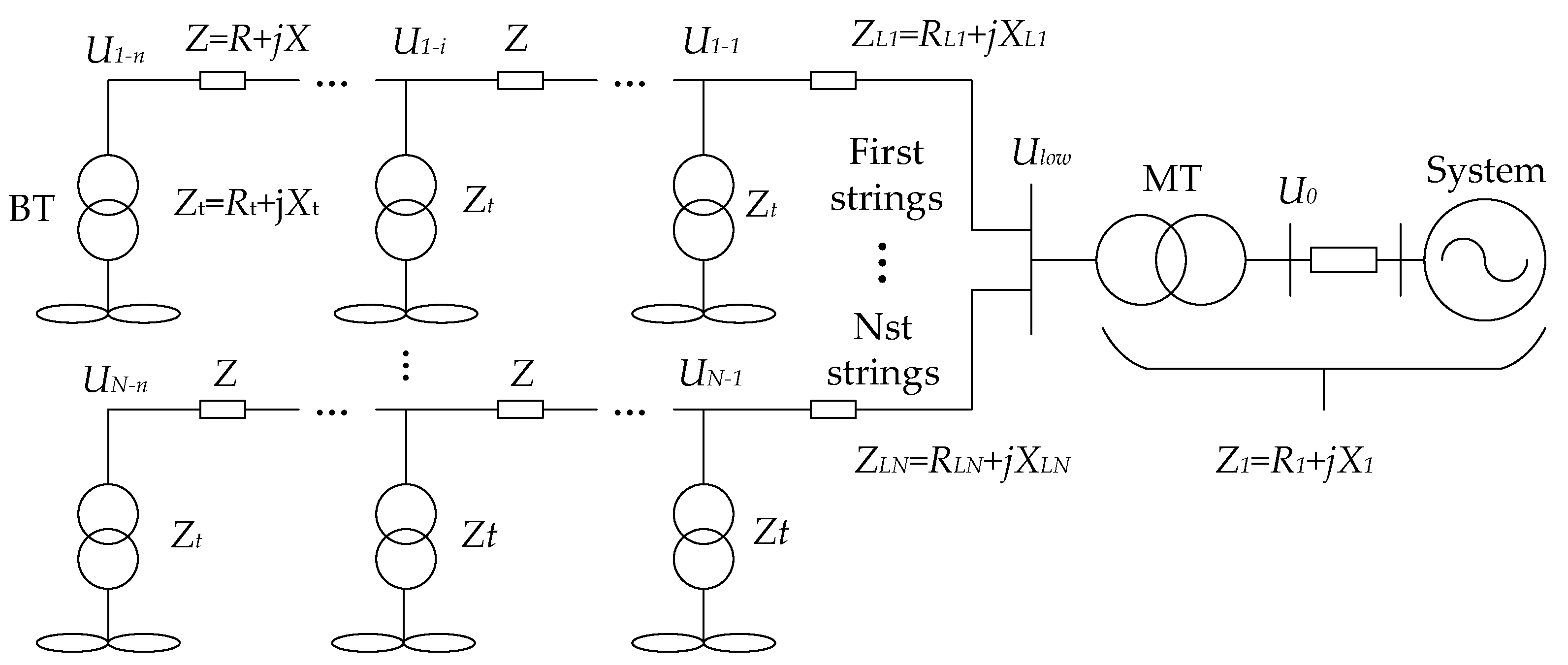
3.3. Reactive Power of the Collector System in the WPP—Voltage Characteristics

During the special period of a blackout, the system cannot provide strong support for the reactive power regulation of the WPPs in a black start. Under a heavy load, a terminal voltage fluctuation of 0.1 p.u will cause the protection circuit of the operating turbine to cut off. Therefore, it is extremely necessary to make full use of the reactive power adjustment capacity of the DFIG. The stability of the terminal voltage must be taken into consideration, to ensure the reliability of the start-up of the WPP.
The topology of the collector line is given in Figure 4. The relationship between the terminal voltage of other turbines and the topology of the collection system is influenced by the reactive power regulation capacity of the DFIG and the reactive power variation of turbines, which is shown in Equation (5).
{ U G - k j Q G - i j = X L j + ( k 1 ) X U Low j R L j U Low     ( i > k ) U G - k j Q G - i j = X L j + ( i 1 ) X U Low j R L j U Low     ( i < k ) U G - k s Q G - n j = X L j + ( n 1 ) X U Low j R L j U Low
where X L j and R L j are the inductance and impedance, respectively, of the first turbine of the collector line j to the converging bus, X is the inductance between the adjacent turbines on the same collector line, ULow is the converging bus voltage, ∂ U G - k j is the terminal voltage variation of turbine k on the collector line j, ∂ Q G - i j is the reactive variation of turbine i on the collector line j, ∂ U G - k s is the terminal voltage variation of turbine k on the collector line s, and ∂ Q G - n j is the reactive variation of turbine n on collector line j.
According to the above equation, the terminal voltage of all of the wind turbines impacted by another turbine’s reactive power output is mainly divided into two types. The first type is the terminal voltage on the same collector line, which is affected by the distance between the two turbines. The longer the distance from turbine to the bus-rod is, the bigger the effect is. The second type of terminal voltage occurs for two turbines on a different collector line. With the increase of the electrical distance between two turbines to the bus-rod, the effect of one turbine’s reactive power variation on the terminal voltage of the other turbine increases.
After the location of the turbine is determined, according to the above analysis, the starting sequence of the turbine is reasonably planned using a reactive power variation when starting turbines.

4. Hierarchical Planning Model of the Energy Storage Configuration

Expanding the two-layered planning model, the hierarchical planning model of the energy storage configuration is established. Three non-linear and coupling factors should be taken into consideration: The number of the starting turbines with energy storage, the optimal positioning of the starting turbine, and the starting sequence for the condition of the reactive power fluctuation constraint.

4.1. Constructing the Capacity Optimization Layer

The upper objective function of the energy storage capacity planning is the maximum starting power PS, which is defined in Equation (6):
max P s = 1 i P i     ( i = 1 , , x ( n + 1 ) k )
The starting time efficiency constraints are given in Equations (3) and (4).
Using the monthly average wind speed as the wind speed condition of the generating turbine in a heavy load month and the number of turbines, X, the initially equipped energy storage can be calculated by Equations (1)–(3). The energy storage capacity CS can then be calculated using Equations (7) and (8):
C S = x P C S - N
P C S - N = α P z - I m + P z - R
where PCS-N is the rated power of the energy storage.

4.2. Energy Storage Capacity and Configuration, and the Starting Efficiency Analysis of the WPP

According to the analysis in Section 2.2, in order to reflect the power loss caused by the causes of scheduling and failure, there are some assumptions being made.
  • The yaw system can capture the wind energy of the wind turbine most of the time.
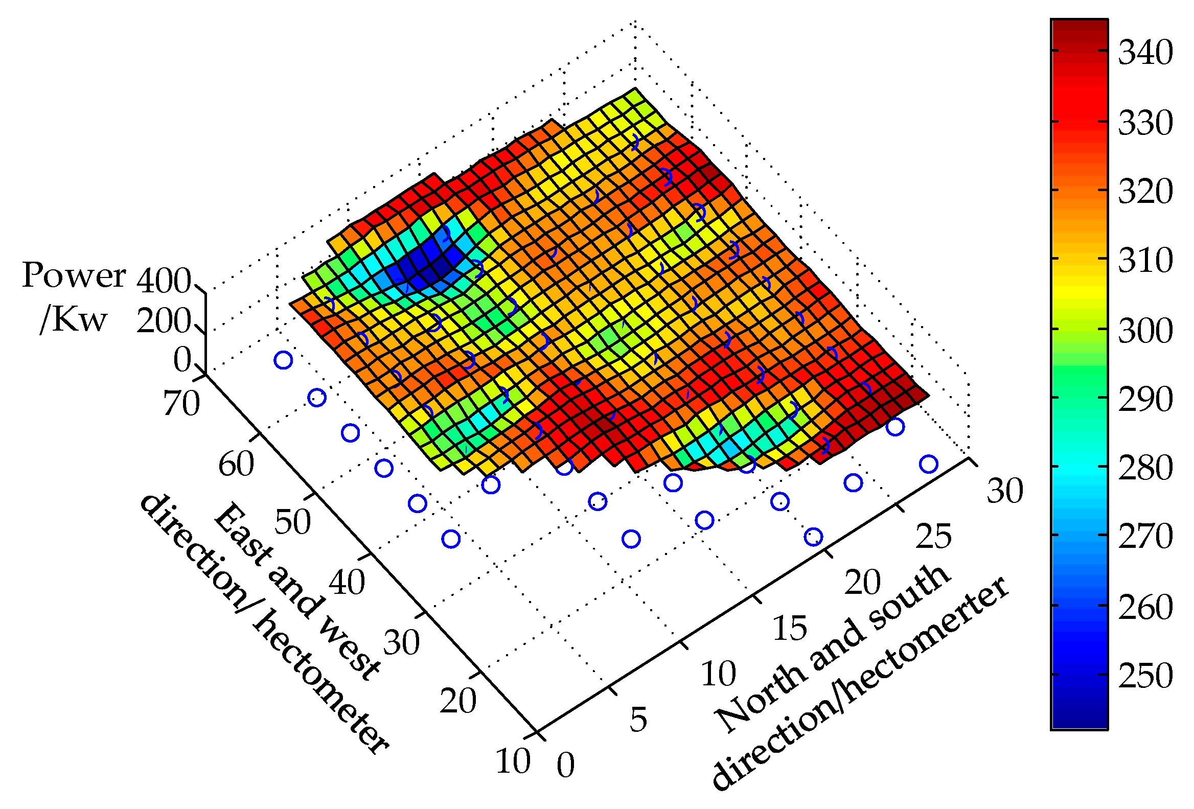
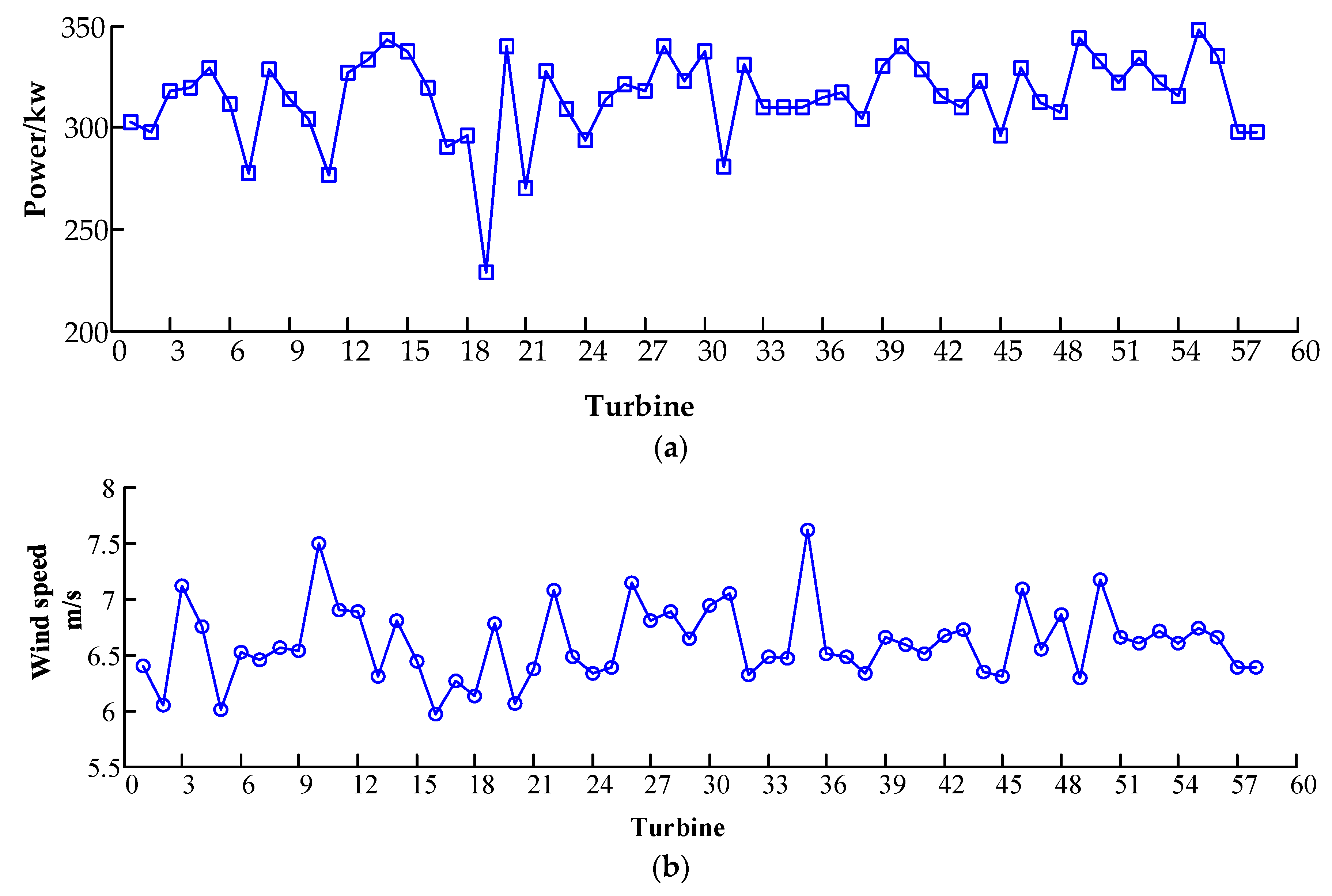
  • The power of each turbine can reflect the overall operation of the turbine.
  • The wind speed can reflect the basic external conditions of the generating turbine to embody the power loss caused by the dispatch and breakdown.
First, under the boundary conditions of the wind speed (Vm-i), the output power (Pw-i), the matching degree between the wind speed, and the output power (η), the wind turbine can be classified and optimized by the SOFM algorithm (a self-organizing feature mapping neural network that effectively solves the obscure and intermixed nonlinear distribution information). Second, the classified turbines should be analyzed and calculated by the size of the correlation factor. In addition, the size of the correlation factors characterizes the influence of the turbines on the wind speed and the output power of the other turbines. Furthermore, the turbine with energy storage is ultimately determined according to the size of the correlation factor.
In order to eliminate the influence of the characteristic differences of an individual turbine on the output results, the input value of the algorithm is the mean value and root-mean-square error after the normalization. The specific flow chart is given in Figure 5.

4.3. The Starting Order Constraint Conditions of the Turbine

In the range of the reactive power regulation capacity of DFIG, the drop value of the terminal voltage must be satisfied with the Equation (9):
max { U G - k j Q G - i j ¯ · Δ Q G - i j , U G - k s Q G - i j ¯ · Δ Q G - i j } 0.06
where Δ Q G - i j is the reactive power variation when starting turbines.
Under heavy load conditions, a terminal voltage fluctuation of 0.1 p.u. will cause the turbine to stop and remove the net. Therefore, in the special period of non-grid support, we should keep a certain margin to ensure the start-up reliability. The drop value of terminal voltage is 0.06 p.u.

4.4. The Solving Method for the Entire Model

First, according to the number, type, self-system power of turbines, and stating performance, at a certain wind speed, the number of turbines with energy storage is determined by Equation (3). Then, the capacity of the energy storage configuration can be determined.
Second, according to the statistical data of the wind speed and the output power of each turbine, in a specific period, the energy storage configuration is determined through the related factors.
Finally, considering the terminal voltage fluctuation constraint, the starting sequence of the turbines is established.

5. Case Study

The effectiveness of the proposed approach was tested on the western Jilin (China) power system. Data from the western Jilin power system for the WPP and the self-system of the turbines are shown in Table 1 and Table 2, respectively.
The wind speed and the output power of each turbine, at sampling intervals of one minute from July to September 2016, are used as the essential data for the classification and optimization of the wind turbines.

5.1. Energy Storage Configuration and Capacity

According to the parameters in Table 2, the following data can be calculated: PZ-Im is 15.2 kW, PZ-R is 3.8 kW, and PZ is 19.0 kW. According to the field measurement, the starting time of a wind turbine is 80 s, which proceeds from receiving the start command to achieving the stable output. Under the condition that average wind speed is 6.6 m/s in July–September, the following data can be calculated from Equation (1): the active power Pw is 300 kW, the power factor cosφ is 0.95, and the apparent power S is 315 kVA. As a result, there are two turbines that can be started at the same time, according to Equation (2).
In a WPP with 58 turbines, the analysis of the number of turbines with store energy is shown in Figure 6, using Equations (3) and (4).
As shown in Figure 6, if all wind turbines are started in 240 s, the WPP needs to have at least seven energy storage cabinets configured. According to Equations (7) and (8), an ESS with a rated power of 320 kW/240 kWh can start a single turbine. Thus, for this WPP, an ESS (a power rating of 2.24 MW and energy capacity of about 1.68 MWh) is required for the black-start.

5.2. Turbines with Energy Storage

Figure 7 is the monthly average wind power distribution, and Figure 8 is the monthly average power distribution. The color columns of the two pictures are identical. If the wind speed and output power are only a direct proportional relationship, the color of the two pictures is the same. However, the actual analysis is not exactly so, and the utilization of wind energy is different in different wind turbines. So, from analyzing the energy storage configuration, we should overall consider the wind condition and the output power.
As shown in Figure 9, the input layer of the SOFM algorithm is the value of the mean square error, the root mean square error of the output power, and the wind speed. The nerve layer is Vm-i, Pw-i and η, and the output layer is class 3. After 1000 iteration calculations, the turbine is divided into three categories in Figure 10.
Table 3 shows the difference between the SOFM algorithm and the traditional empirical formula. The traditional empirical formula determined the classification of units according to the size of Cp, which can be calculated by the Equation (10):
C p = P W P Z 1 2 π V m 3
Traditional empirical formula only considers the relationship between average wind speed and average power; however, SOFM algorithm considers the non-linear relationship between the wind speed (Vm-i), the output power (Pw-i), the matching degree between the wind speed, and the output power (η). From Table 3, we can see the difference of the classification results by (a) calculating the Cp, and (b) using the SOFM, in which the red font is the first class of unit by analyzing the SOFM. The first class used by SOFM is stray distribution in various categories by traditional empirical formula. So, the correctness of SOFM solving the obscure and intermixed nonlinear distribution information is verified.
As shown in Figure 9 and Figure 10, 19 turbines are selected as first class turbines by the SOFM algorithm. The following is the correlation analysis based on the eigenvalues.
  • Between the correlation coefficients of turbine 4 and turbine 3, 35 is slightly lower, and the correlation coefficient between turbine 4 and the other turbines is greater than 0.9.
  • The average correlation coefficient between turbine 28 and the other turbines is 0.87. The average correlation coefficient between turbine 28 and the other turbines is 0.78.
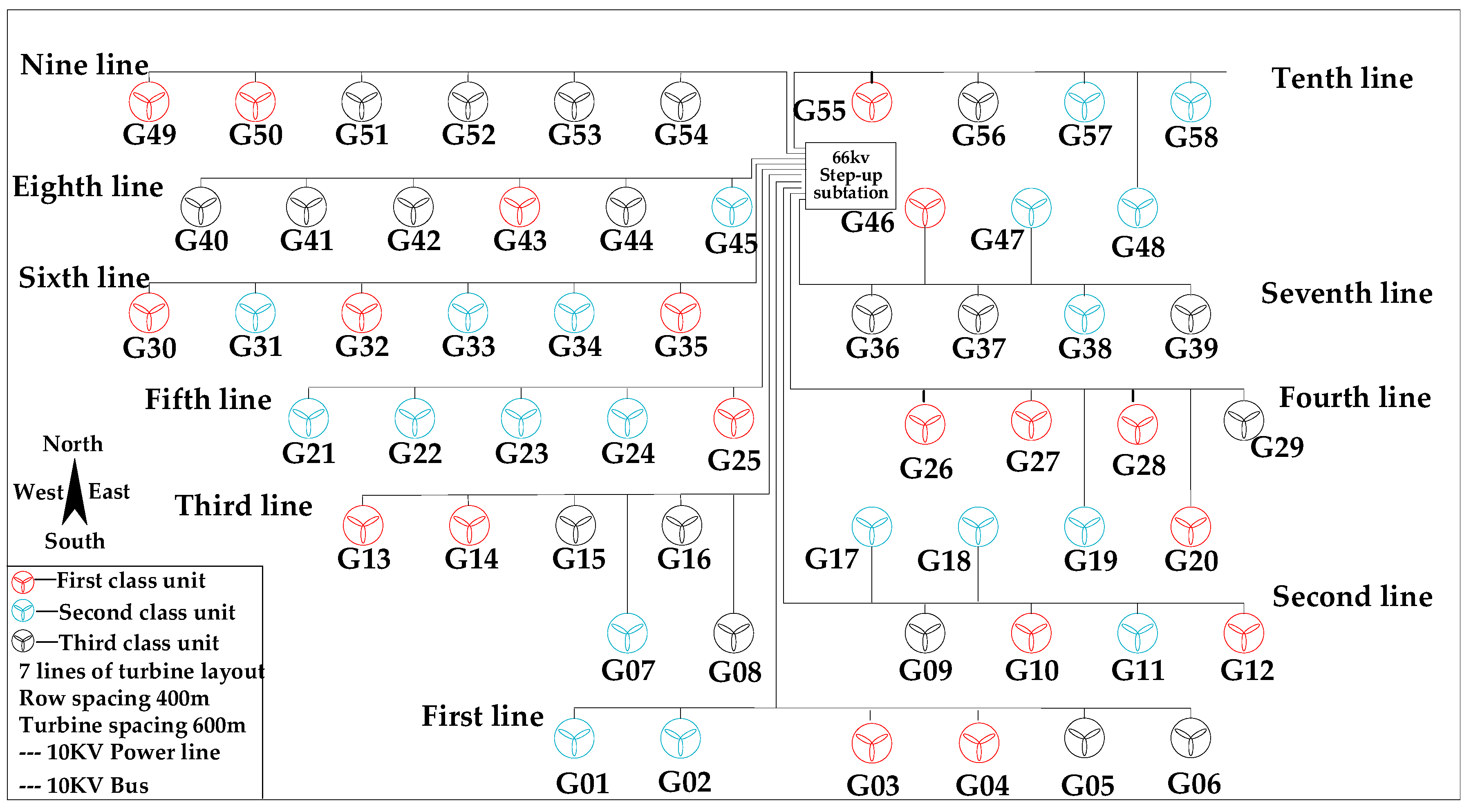
  • Therefore, we select a turbine whose the correlation coefficient is greater than 0.7. The priority turbines are then 3, 4, 25, 26, 28, 46, and 55.

5.3. Plan for the Starting Sequence of the Turbines

According to the field testing and the data provided by wind turbine manufacturers, the maximum reactive power variation of G58-850 DFIG is 0.22 MW.
  • For the condition of i < 3 from Equations (5) and (9), the following steps are the plan for the starting sequence of the turbine.
  • For turbines on the same collector line: When a turbine with energy storage is preferentially started, the other turbines are started in sequence from near to far, according to the distance of the bus-bar.
  • For turbines on different collector lines: Other collector lines that are unequipped with stored energy are started in sequence from near to far, according to the distance of the bus-bar.
According to the above starting sequence planning principles, such as the power generation of line 5, for the same collector lines, the turbines are started according to the sequence of G25 to G24, G23, G22, and G21. When all of the turbines with energy storage are started completely, the other lines are launched from power generation line 9, power generation line 8, and power generation line 6 to power generation line 3.

6. Conclusions

In this paper, a method for energy storage configuration based on the analytic hierarchy process (AHP) is proposed. Starting from the self-system of a single turbine demand, the method was verified by the measured data of the WPP. The results of this study can be summarized as follows.
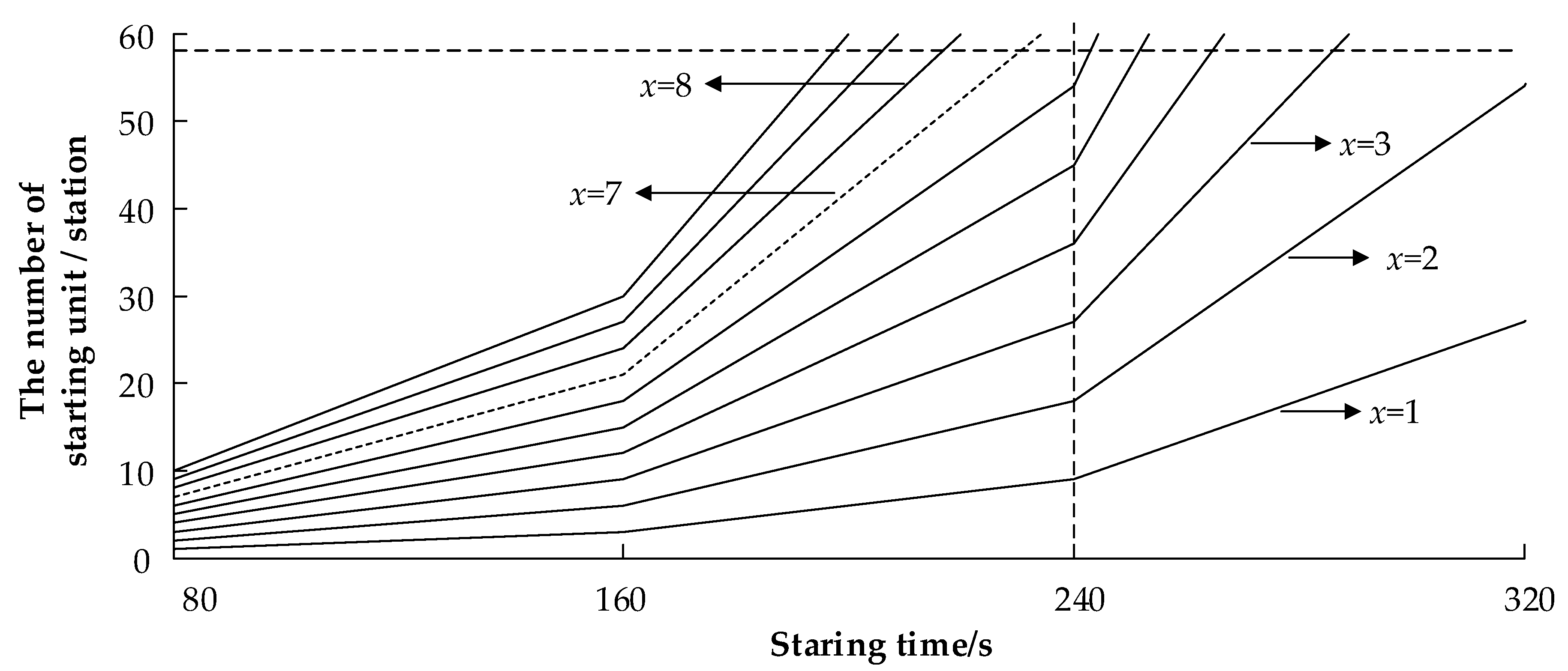
  • With respect to the energy storage configuration and capacity, a single turbine with the energy storage to drive other turbines is adopted. In 240 s, seven wind turbines with ESSs (a power rating of 2.24 MW and energy capacity of 1.68 MWh) are available in a 49.5 MW WPP.
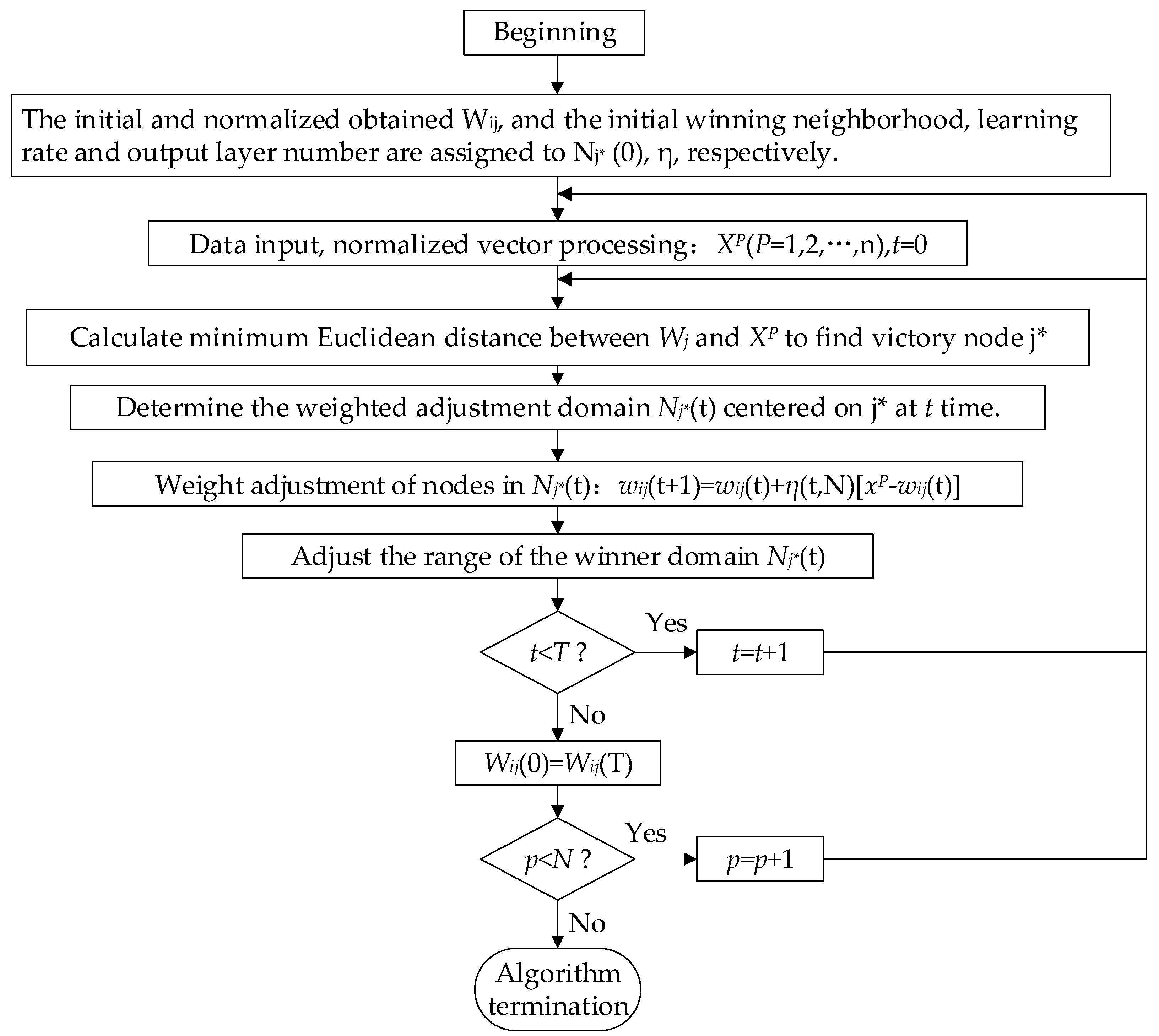
  • In terms of the distribution of the energy storage, according to the historical operation state of the turbine, the turbines are optimized and classified by the SOFM algorithm under the boundary conditions of the wind speed (Vm-i), the output power (Pw-i), and the matching degree between the wind speed and the output power (η). Next, a turbine with a correlation coefficient of greater than 0.7 is selected. This is accomplished in order to complete the energy storage layout and utilization maximization of the initial power.
  • In order to solve the starting sequence of the turbines caused by the configuration and layout of the energy storage, the following conditions are required, in order to complete the self-starting of the WPP. First, a turbine with energy storage is used as the initial power source. Second, other turbines on the same collector line are started using the starting sequence of ‘n + 1’. The maximum reactive power variation of the turbine is 0.22 MW, and terminal voltage fluctuation is 0.06 p.u.
  • In order to reduce the capacity of the frequency converter of the battery energy storage system, the reactive power compensation device in the WPP can be constructed or fully utilized.
The new method proposed in our article is that the ESS is configured with a small capacity on the side of the turbine, which can achieve the black-start for a WPP with small energy storage cabinets as the power source. Although it solves the problems of high cost, multi-job energy storage, and technology, this method should be based on the transformation of wind turbines. So far, we haven’t found a perfect way to achieve this goal, which is the main direction of our next research.

Author Contributions

C.L., J.L., and H.Y. proposed this study; S.Z. and J.Z. wrote the paper; J.Q. and Q.G. reviewed and edited the manuscript. All authors read and approved the manuscript.

Funding

This research was funded by the National Natural Science Foundation of China (U1766204), Industrial Innovation of Jilin Province Development and Reform Commission (2017C017-2), and Important Subject for Reform and Development of Inner Mongolia Power Supply Bureau (Research on Energy Storage Technology and Black Start Scheme of Western Mongolia Power Grid, DK-ZXZB-2018-DLJSYJS0401-0077).

Acknowledgments

This research was funded by the National Natural Science Foundation of China (U1766204), Industrial Innovation of Jilin Province Development and Reform Commission (2017C017-2), and Important Subject for Reform and Development of Inner Mongolia Power Supply Bureau (Research on Energy Storage Technology and Black Start Scheme of Western Mongolia Power Grid).

Conflicts of Interest

The authors declare no conflict of interest.

Nomenclature

Variables
RRadius of the wind wheel
ρAir density
VmAverage wind speed of the initially starting turbine
PZPower of the plant demand for the starting turbine demand
PZ-ImPower of the synchronous motor
PZ-RPower of the other equipment
PZSelf-starting power of wind turbine
CpWind energy utilization coefficient
αCapacity margin
xNumber of turbines initially starting
nNumber of starting turbines initially equipped energy storage
kStarting batch
NTurbine number
tfTotal time length of the wind turbine from starting turbine to stable output
TallStarting constraint time of the wpp
X L j Inductance of the first turbine of collector line to the converging bus
R L j Impedance of the first turbine of collector line to the converging bus
jLine j
sLine s
XInductance between the adjacent turbines on the same collector line
ULowConverging bus voltage
U G - k j Terminal voltage variation of turbine k on the collector line j
Q G - i j Reactive variation of turbine i on the collector line j
Q G - k s Terminal voltage variation of turbine k on the collector line s
Q G - n j Reactive variation of turbine on the collector line j
iNumber of the wind turbine
kNumber of the wind turbine
PSMaximum power
PiStarting power of turbine i
CsCapacity of the energy storage
Vm-iWind speed
Pw-iOutput power
ηMatching degree
Q G - i j Reactive power variation
PWActive power
SApparent power
Abbreviation
WPPWind power plant
ESSEnergy storage system
DFIGDoubly fed induction generator

References

  1. Leng, Y.J.; Lu, Q.; Liang, C.Y. Black-start decision making based on collaborative filtering for power system restoration. Int. J. Electr. Power Energy Syst. 2018, 100, 279–286. [Google Scholar] [CrossRef]
  2. Sun, P.; Liu, Y.; Qiu, X.; Wang, L. Hybrid multiple attribute group decision-making for power system restoration. Expert Syst. Appl. 2015, 42, 6795–6805. [Google Scholar] [CrossRef]
  3. Qu, H.; Liu, Y. Maximizing restorable load amount for specific substation during system restoration. Int. J. Electr. Power Energy Syst. 2012, 43, 1213–1220. [Google Scholar] [CrossRef]
  4. Liu, Y.; Gu, X. Skeleton-network reconfiguration based on topological characteristics of scale-free networks and discrete particle swarm optimization. IEEE Trans. Power Syst. 2007, 22, 1267–1274. [Google Scholar] [CrossRef]
  5. Chou, Y.T.; Liu, C.W.; Wang, Y.J. Development of a black-start decision supporting system for isolated power systems. IEEE Trans. Power Syst. 2013, 28, 2202–2210. [Google Scholar] [CrossRef]
  6. Liu, Y.T.; Wang, H.T.; Hua, Y.E. Power System Restoration Theory and Technology, 1st ed.; Science Press: Beijing, China, 2014; pp. 15–16. [Google Scholar]
  7. Li, J.H.; Kong, M.; Mu, G. Overview of re-searches on key technologies of power system black-start. South. Power Syst. Technol. 2017, 11, 68–77. [Google Scholar] [CrossRef]
  8. Liang, H.; Gu, X.P. Black-start network partitioning based on spectral clustering. Power Syst. Technol. 2013, 37, 372–377. [Google Scholar]
  9. Jiao, J.; Liu, Y. Optimization of units’ restoration sequence during network reconfiguration process based on robust optimization. Trans. China Electrotech. Soc. 2017, 32, 77. [Google Scholar] [CrossRef]
  10. Jerry, J.A. A framework for power system restoration following amajor power failure. IEEE Trans. Power Syst. 1995, 9, 1480–1485. [Google Scholar] [CrossRef]
  11. Liu, J.; Wen, J.Y.; Yao, W.Y.; Long, Y. Solution to short-term frequency response of wind farms by using energy storage systems. IET Renew. Power Gener. 2016, 10, 669–678. [Google Scholar] [CrossRef]
  12. Mehrasa, M.; Pouresmaeil, E.; Sepehr, A.; Pournazarian, B.; Marzband, M.; Catalão, J.P. Control Technique for the Operation of Grid-Tied Converters with High Penetration of Renewable Energy Resources. Electr. Power Syst. Res. 2019, 166, 18–28. [Google Scholar] [CrossRef]
  13. Liao, S.W.; Yao, W.; Han, X.N.; Wen, J.Y.; Cheng, S.J. Chronological operation simulation framework for regional power system under high penetration of renewable energy using meteorological data. Appl. Energy 2017, 203, 816–828. [Google Scholar] [CrossRef]
  14. Mehrasa, M.; Pouresmaeil, E.; Pournazarian, B.; Sepehr, A.; Marzband, M.; Catalão, J. Synchronous Resonant Control Technique to Address Power Grid Instability Problems Due to High Renewables Penetration. Energies 2018, 11, 2469. [Google Scholar] [CrossRef]
  15. Mehrasa, M.; Adabi, M.E.; Pouresmaeil, E.; Adabi, J.; Jørgensen, B.N. Direct Lyapunov control (DLC) technique for distributed generation (DG) technology. Electr. Eng. 2014, 96, 309–321. [Google Scholar] [CrossRef]
  16. Mehrasa, M.; Rezanejhad, M.; Pouresmaeil, E.; Catalão, J.P.; Zabihi, S. Analysis and control of single-phase converters for integration of small-scaled renewable energy sources into the power grid. In Proceedings of the 2016 7th Power Electronics and Drive Systems Technologies Conference, Tehran, Iran, 16–18 February 2016; pp. 384–389. [Google Scholar] [CrossRef]
  17. Zareifard, M.T.; Savkin, A.V. Model predictive control for output smoothing and maximizing the income of a wind power plant integrated with a battery energy storage system. In Proceedings of the 2016 35th Chinese Control Conference (CCC), Chengdu, China, 27–29 July 2016. [Google Scholar] [CrossRef]
  18. Yan, G.G.; Sun, Z.J.; Mu, G. Collector system voltage regulation oriented reactive power control strategy for WPP. Trans. China Electrotech. Soc. 2015, 30, 140–146. [Google Scholar] [CrossRef]
  19. Zhu, Y.; Zang, H.; Cheng, L. Output power smoothing control for a wind farm based on the allocation of wind turbines. Appl. Sci. 2018, 8, 980. [Google Scholar] [CrossRef]
  20. Dai, J.F.; Tang, Y.; Wang, Q. Black-start technology for local power grid via PMSG-based wind power generation. In Proceedings of the 2016 Future Energy Electronics Conference & ECCE Asia, Kaohsiung, Taiwan, 1–6 June 2016. [Google Scholar] [CrossRef]
  21. Liu, L.; Wu, J.; Mi, Z. A feasibility study of applying storage-based wind farm as black-start power source in local power grid. In Proceedings of the 6th International Conference on Smart Grid and Clean Energy Technologies, Chengdu, China, 19–22 October 2016. [Google Scholar] [CrossRef]
  22. Lin, W.X.; Jovcic, D. Power balancing and dc fault ride through in DC grids with dc hubs and WPPs. IET Renew. Power Gener. 2015, 9, 847–856. [Google Scholar] [CrossRef] [Green Version]
  23. Mohammad, B.D.; Sajjad, S.M.; Amirnaser, Y. Fractional-order Sliding-Mode Control of Islanded Distributed Energy Resource Systems. IEEE Trans. Sustain. Energy 2016, 4, 1482–1491. [Google Scholar] [CrossRef]
  24. Du, K.; Liu, Y.; Ye, M. Capacity configuration strategy of energy storage power station when assisting the WPP in integrating into the preliminary black-start. Power Syst. Protect. Control 2017, 45, 62–68. [Google Scholar] [CrossRef]
  25. Yuan, H.; Mi, Z.; Du, P. Research of the transformer energization control strategy applied for storage-based wind farm self-start. In Proceedings of the 2016 IEEE Information Technology, Networking, Electronic and Automation Control Conference, Chongqing, China, 20–22 May 2016; pp. 543–547. [Google Scholar] [CrossRef]
  26. Sun, F.; Zhao, Y.; Wang, G. Study on charging and discharging characteristics of ESS in wind storage power plant under the condition of black-start. Adv. Mater. Res. 2015, 70, 443–448. [Google Scholar] [CrossRef]
  27. Tang, Y.; Dai, J.F.; Feng, Y.X. Cooperative frequency control strategy for WPP black-start based on virtual inertia. Autom. Electr. Power Syst. 2017, 41, 19–24. [Google Scholar] [CrossRef]
  28. Li, J.H.; Fan, X.K.; Mu, G. Economic Analysis of Energy Storage Applied to Grid Frequency Regulation. J. Glob. Energy Interconnect. 2018, 1, 355–360. [Google Scholar] [CrossRef]
  29. Li, J.H.; Ma, Y.B.; Mu, G.; Feng, X.C.; Yan, G.G.; Guo, G.; Zhang, T.Y. Optimal Configuration of Energy Storage System Coordinating Wind Turbine to Participate Power System Primary Frequency Regulation. Energies 2018, 11, 1396. [Google Scholar] [CrossRef]
  30. Li, C.P.; Cao, P.J.; Li, J.H.; Zhao, B. Review on reactive voltage control methods for large-scale distributed PV integrated grid. J. Northeast Dianli Univ. 2017, 37, 82–88. [Google Scholar] [CrossRef]
  31. Li, J.H.; Zhang, T.Y.; Qi, L.; Yan, G.G. A Method for the Realization of an Interruption Generator Based on Voltage Source Converters. Energies 2017, 10, 1642. [Google Scholar] [CrossRef]
  32. Wang, Y.B.; Ye, R.L.; Zhang, S. Study on the optimal allocation of output transission capacity and energy storage capacity of WPP based on CVaR. Electr. Eng. 2017, 18, 69–74. [Google Scholar]
  33. Ai, X.M.; Li, JM.; Fang, J.K.; Yao, W.; Xie, H.L.; Cai, R.; Wen, J.Y. Multi-Time-Scale Ramp-Rate Control for Photovoltaic Plants Equipped with Battery Energy Storage. IET Renew. Power Gener. 2018, 12, 1390–1397. [Google Scholar] [CrossRef]
  34. Li, J.H.; Gao, F.J.; Yan, G.G.; Zhang, T.Y.; Li, J.L. Modeling and SOC estimation of lithium iron phosphate battery considering capacity loss. Protect. Control Mod. Power Syst. 2018, 3, 61–69. [Google Scholar] [CrossRef]
  35. Wu, T.; Li, H.W. Investigation of black-start for north China power system by shisanling hydroelectric generating sets. Power Syst. Technol. 2001, 25, 56–58. [Google Scholar]
Figure 1. Black-start process based on the wind power plant (WPP) with energy storage system (ESS).
Energies 11 03394 g001
Figure 2. Structure diagram of wind-storage generation system in the black-start.
Energies 11 03394 g002
Figure 3. Energy storage configuration of WPP with ESS.
Energies 11 03394 g003
Figure 4. Topology of a collector line in WPP.
Energies 11 03394 g004
Figure 5. Flow chart for the self-organizing feature mapping (SOFM) algorithm.
Energies 11 03394 g005
Figure 6. The number of initial configuration turbines.
Energies 11 03394 g006
Figure 7. Monthly average wind power distribution.
Energies 11 03394 g007
Figure 8. Monthly average power distribution.
Energies 11 03394 g008
Figure 9. The wind power fluctuation of the turbine about (a) wind power and (b) wing speed.
Energies 11 03394 g009
Figure 10. Turbine layout.
Energies 11 03394 g010
Table 1. The parameters of WPP.
ParameterValueUnit
Installed capacity49.5MW
Space between turbine400m
Voltage10.5kV
Installed sets58-
Type of turbineG58-850-
Row number of turbine7-
Collector line10-
Line modelLGJ-125/20-
Table 2. The parameters of G58-850’DFIG.
ParameterValueUnit
Ventilator2kW
Heating cabinet1kW
Lighting cabinet0.2kW
Converter0.4kW
Radiator transfer2.8kW
Pressure transfer1.5kW
Circulating pump1.2kW
Heater2kW
Yaw motor6kW
Heating engine room0.8kW
Lubricating oil pump0.6kW
Fluid pump1.1kW
Table 3. Comparison of classification results by (a) calculating the Cp, and (b) using the SOFM.
(a)(b)
First class2, 5, 13, 15, 16, 18, 20, 25, 32, 38, 41, 44, 49First class3, 4, 10, 12, 13, 14, 20, 25, 26, 27, 28, 30, 32, 35, 43, 46, 49, 50, 55
Second class1, 6, 8, 9, 17, 23, 24, 33, 34, 36, 37, 39, 40, 45, 47, 52, 55, 56, 57, 58Second class1, 2, 7, 11, 17, 18, 19, 21, 22, 23, 24, 31, 33, 34, 38, 45, 47, 48, 57, 58
Third class3, 4, 7, 10, 11, 12, 14, 19, 21, 22, 26, 27, 28, 29, 30, 31, 35, 42, 43, 46, 48, 50, 51, 53, 54Third class5, 6, 8, 9, 15, 16, 29, 36, 37, 39, 40, 41, 42, 42, 44, 51, 52, 53, 54, 56

