Abstract
The crossflow turbines commonly used in small hydropower systems have a single nozzle. We are unaware of any studies of double-nozzle crossflow turbines which could have twice the power output of the single-nozzle design by doubling the flow through the same runner, with a high maximum efficiency. We present a computational analysis of a double-nozzle crossflow turbine, to determine the turbine efficiency and fundamental flow patterns. This work was based on a single-nozzle crossflow turbine with a maximum efficiency of 88%, one of the highest reported in the open literature through extensive experimental measurements. Previous numerical studies on this turbine have shown that the water flow in the runner was confined to less than half the runner periphery, implying that the other half could be used to double the runner power output by employing a second nozzle. We show that adding a second, identical nozzle without making any other changes to the design achieves a doubling of the power output. The dual-nozzle turbine, therefore, has the same efficiency as the original turbine. We also investigate the use of a slider to control the flow at part-load and show that part-load efficiency of the double-nozzle is very similar to that of the original turbine. This demonstrates the feasibility of using two nozzles for crossflow turbines.
1. Introduction
Crossflow turbines are used in small hydropower systems, mainly in the remote locations in developing countries, due to their inherent simplicity in design and low manufacturing cost. One major practical problem is that they suffer from lower efficiency than Pelton and Francis turbines, which can achieve maximum efficiency of 90% or above. Most practical crossflow turbines operate at 70–85% efficiency [1,2,3,4]. Although Desai [5] and Totapally and Aziz [6] achieved a maximum efficiency of and respectively for a small-scale 0.53 kW turbine through extensive experimental development, no larger turbines of similar performance have been built and tested. We speculate that this is due to a lack of understanding of the design principles for achieving high efficiency, as developed by Adhikari and Wood [7] for the nozzle and by Adhikari and Wood [8] for the nozzle and the runner designs.
A conventional crossflow turbine has a single nozzle as shown in Figure 1. The turbine works on the principle that head is converted into kinetic energy in the nozzle before the flow enters the runner which operates at atmospheric pressure, Adhikari and Wood [7]. This is similar to the operation of Pelton turbines which can achieve more than 90% efficiency and are often designed with multi-jets, Zhang [9]. The major differences between the two are that the flow in crossflow turbines passes twice through the runner and is parallel to the blades unlike the impulsive action of the water jet on Pelton buckets. Adhikari and Wood [7] noted that the most efficient crossflow turbines had an entry arc, , for water passing to the first stage of the runner, of as indicated in Figure 1. It is shown in the Appendix A that a high efficiency crossflow turbine will have a second stage smaller than the first, so the periphery of the two stages is less than , implying that the remaining blades of the runner can be utilized by a second nozzle which should not interfere with the flow due to the first, provided that the two stages are contiguous. This occurred in the simulations of Adhikari [10]. No previous study has considered a crossflow turbine with two nozzles, similar to a multi-jet Pelton turbine. Here, we present a computational analysis of a double-nozzle crossflow turbine, with the primary objective of evaluating the turbine efficiency and internal flow patterns at constant head H with flowrate Q varying up to the maximum . This study is based on the single-nozzle turbine with very high efficency, , studied experimentally by Desai [5] and numerically by Adhikari [10].
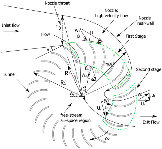
Figure 1.
A schematic illustration of a single-nozzle crossflow turbine.
A second, identical nozzle was added and no modifications were made to the runner. This allowed a systematic comparison with the performance and flow features between the single and double nozzle turbines.
The possible advantages of the double-nozzle crossflow turbine are: (1) a more compact runner utilizing more blades at twice the flow rate of a single-nozzle runner, (2) runner vibration should be reduced because of more uniform loading of the runner, and (3) easier part-load control as one nozzle can be closed if . If the double-nozzle crossflow turbine maintains the high efficiency of the single-nozzle design, these advantages can be practically realized. Thus the main purpose of this paper is to evaluate the maximum efficiency of the double-nozzle design at maximum and part-flow operations compared to the single-nozzle case of [5] as studied by Adhikari [10] and Adhikari and Wood [8]. The reader is referred to those references for the detailed performance and flow analysis of the single-nozzle turbine. A comprehensive review of the design of efficient single-nozzle turbines is provided in [8], and for brevity, the literature on single-nozzle turbines is not reviewed here. The relevant results to this work are briefly discussed in the results section.
The remainder of this paper is organized as follows. Section 2 describes the design principle of the double-nozzle turbine. Section 3 describes the computational methodology by which we investigate the performance of the double-nozzle design. Section 4 presents the results of the computational studies in which turbine performance and important flow features of the double-nozzle turbine are analyzed and finally, Section 5 summarizes the findings.
2. Double-Nozzle Design
References [7,8,10] provide a detailed computational analysis of the performance and flow of the single-nozzle 0.53 kW turbine with , which was experimentally tested by Desai [5]. An examination of the computed flow in the runner at maximum efficiency suggested that double-nozzle runner of similar maximum efficiency could be designed. Figure 2 shows the two nozzles identical to those used by Desai [5], placed 180 apart on the periphery of the rotating runner. The nozzles accelerate the inlet flow and direct it to the runner blades at angle . A unique design feature of the double-nozzle crossflow turbines is that the flow from each nozzle passes twice through the runner but in opposite directions. The flow enters the first stage, then crosses the runner central space, and exits through the second stage where additional power is extracted [8,11]. Remarkably, the double-nozzle turbine can have four power producing stages in the runner. This means a more uniform loading of the runner blades.
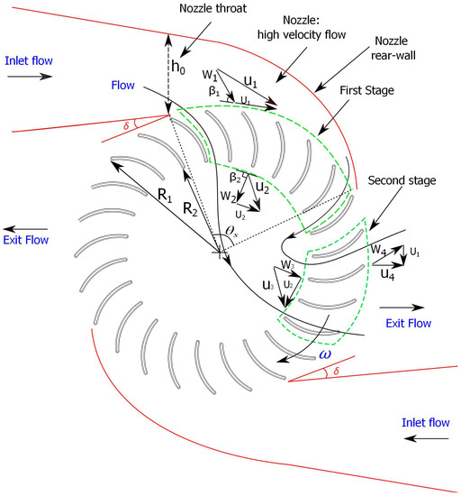
Figure 2.
A schematic illustration of a double-nozzle crossflow turbine. Note the anti-symmetric orientation of the nozzles at 180.
Since the flow passes twice through the runner and both stages extract power, the double-nozzle design presents a unique challenge in avoiding losses in the runner inner space and the second stage. The flows exiting the first stages could deflect each other in the runner interior and cause significant losses in the second stage by opposing the runner rotation. This may be a critical aspect of double-nozzle operation and thus any flow deflection in the runner interior must be investigated. Clearly, if the flows pass through the runner without interference, then the runner can achieve the same maximum efficiency as that of the single-nozzle turbine.
Current commercial crossflow turbines are designed with a guide vane in the nozzle to control the velocity and inlet flow angle . A guide vane is located upstream of the nozzle throat in Figure 2. However, according to Adhikari and Wood [7], a guide vane reduces the quality of the runner entry flow by splitting it into two jets and producing non-uniform entry flow angles which can cause significant drop in runner efficiency. This study considers slider control of the entry flow, instead of a guide vane [10,12]. A slider is a thin curved metal sheet that “slides” over the blades to reduce at part-load. Adhikari [10] demonstrated that slider control maintained high efficiency during part-load operation of the 88% efficient turbine. For a double-nozzle turbine, however a rigid metallic slider is not useful at . This is because retraction of the first nozzle slider would block the exiting flow from the second nozzle, and vice versa, resulting in loss of runner performance. However, a retractable flexible slider can be designed to slide straight along the outside of the nozzle but then in a circular arc over the runner entry. Furthermore, the required reduction in for dual-nozzle turbines is likely to be less than for single-nozzle as one nozzle can be closed when .
The schematic of the original 0.53 kW turbine with entry arc and its design parameters are given in Figure 3 and Table 1 respectively. This turbine was redesigned to include a second nozzle and sliders on both nozzles. Their position and operation will be described in Section 4 after considering full-load operation.
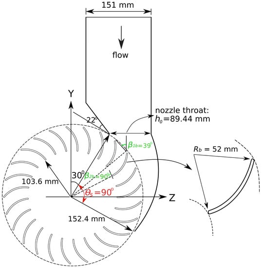
Figure 3.
Schematic of the single-nozzle 0.53 kW turbine with . Note that the turbine does not have a guide vane.

Table 1.
Design parameters of the 0.53 kW turbine (88% efficiency).
3. Computational Methodology
The RANS computation adopted in this study is identical to that described in our previous work [7] and so no detailed description of the computational model is given here. The reader is referred to that reference for the description of the RANS model, grid resolution, boundary conditions, and a demonstration that the predicted turbine power output was within 6% relative error of the measured values. Further, Adhikari and Wood [8] showed that gravitational effects were not important for crossflow turbine operation, so the effects of gravity were not considered in this study. The RANS computations used the commercial CFD code ANSYS CFX (V17.0) [13]. The only difference in the computational domain is the use of double-nozzle instead of a single nozzle. So the number of mesh elements required is greater for the mesh independent results, which are presented below.
The flow in crossflow turbines consists of water and air, which is characterized by free-surface effects. The flow was modelled as a homogeneous flow with free-surface effects between water and air. In a homogeneous multiphase flow, each fluid may possess its own flow field or both fluids may share a common flow field. In this model, air and water are assumed to share the same pressure and velocity fields as well as the turbulence fields, which means that RANS equations are solved for both water and air. In a free-surface flow, water and air are mixed only at the macroscopic scale with a discernible interface [13,14]. The free-surface model resolves the interface between the two. We conducted steady and unsteady RANS simulations with the SST turbulence model with the standard values of the model constants [13]. It was found that the steady simulations were as accurate as the unsteady ones in determining the output power, and quicker to perform, so all results given here were from the steady calculations. It is noted that the flows in the nozzle and the runner entry were entirely water, in other words, were single phase. The multiphase model is needed primarily for the second stage and runner exit flow.
An unstructured tetrahedral mesh with hexahedral elements in the near wall region was used to discretize the computational domain. The computational domain of the double-nozzle turbine is shown in Figure 4. Note that the distinction between Nozzle 1 and 2 is arbitrary and that the simulations were of the complete dual-nozzle geometry; no assumption of flow symmetry was made to reduce the computational domain. A typical computational mesh is shown in Figure 5. The computational domain was divided into two sub-domains: stationary (nozzle) and rotating (runner). A general grid interface (GGI) connected the two domains, which allows updating on interface position at each time step while the relative positions of the grids on each side of the interface change due to runner rotation [13]. The GGI uses interpolation to communicate between non-matching grid points [13].
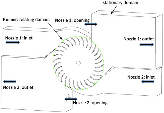
Figure 4.
Schematic of the computational domain of the double-nozzle turbine.
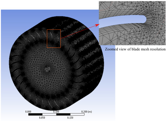
Figure 5.
A typical computational mesh of the runner.
A grid independence test was conducted by refining the grid size until an acceptable accuracy was achieved for the power output . Grid resolution was systematically assessed by computing the value of , which is the non-dimensional distance of the first mesh node from the wall, to ensure 5 because the SST model gives better accuracy at 5 [13,15]. For a single-nozzle turbine, a total of 8.4 million elements was required to make nearly independent of the grid; there was less than 0.1% uncertainty in the computed results due to grid resolution. Similarly, for the double-nozzle turbine, a total of 13.1 million elements produced a at the maximum efficiency point, flow rate = 46 lps, head H = 1.337 m and runner speed N = 199.1 revolutions per minute (RPM), whose numerical uncertainty due to grid resolution is about 0.18% as shown in Table 2. A detailed analysis and results for a single-nozzle turbine can be found in references [7,10]. The inlet and outlet boundary conditions were specified using the experimentally tested values for the operating head H and flow rate Q respectively. Total pressure corresponding to H was specified at the inlet with the turbulence intensity of 5%. Mass flow rate was specified at the outlet. The openings shown in Figure 4, sometimes called “vents”, allow the free flow of air, but not water, in and out of the computational domain. Most commercial crossflow turbines have vents to maintain free-surface flow in the runner and to ensure that the runner entry is at atmospheric pressure. Computationally, the “opening” type boundary condition was specified for the vents. A uniform profile of the inlet flow was assumed at the upstream boundaries of the computational domain shown in Figure 4 as no experimental data on velocity profile was available. The effect of non-uniformity at the inlet on the runner performance should be small as the inlet was kept far upstream from the runner. The location of the inlets was identical to that of the single inlets in [7,10]. For the single nozzle, the maximum relative error between the experimental and CFD results for was 3.84% at = 46 lps and H = 1.337 m, and 0.51% at , which is within the numerical uncertainty mentioned above. This is an accurate prediction of the turbine performance. Given the similarity between the meshes used for the single and dual nozzle simulations, we expect a similar maximum relative error, but we emphasize that there are no experimental studies of dual nozzle crossflow turbines with which to compare the simulations.

Table 2.
Grid convergence results of the double-nozzle turbine at maximum efficiency.
4. Results and Discussion
In order to evaluate the performance of the double-nozzle runner and characterize the main flow features, computations were performed at design flow lps per nozzle, and part-flow down to 20 lps. For all simulations, H = 1.337 m. The results are compared to the corresponding ones for the single-nozzle turbine with the same and H.
The performance comparison is shown in Figure 6. The double-nozzle turbine achieved a slightly greater maximum efficiency than the single-nozzle: 89.12%, compared to the measured [5], and 88.45% from the RANS computations [10]. Thus the double-nozzle performance is similar to that of the single-nozzle considering the numerical uncertainty mentioned above. This is a remarkable performance that justifies the use of two nozzles without having to redesign the nozzle or the runner. It is clear from Figure 6 that adding the second nozzle does not change for maximum efficiency. This is to be expected from the analysis of [7] for the optimum speed if it is further assumed that the flows leaving the first stages do not interfere with each other. Therefore, the power density, which is the total power produced per unit runner volume, is doubled for the same runner.
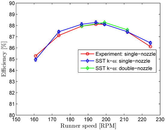
Figure 6.
Comparison of single- and double-nozzle performance at = 46 lps per nozzle and head H = 1.337 m.
To study the performance and the flow features at part-flow operation, computations were performed at Q = 40, 30 and 20 lps per nozzle and H = 1.337 m for both turbines by implementing the slider mechanism investigated in [10,12] for single-nozzle turbines.
4.1. Flow and Performance of Single-Nozzle Turbine
Figure 7, taken from [7], shows the flow in the single-nozzle turbine at . This and all subsequent figures show the velocity contours at the midplane of the turbine. There is no separation from the blades and the contiguous first and second stages constitute less than half the runner periphery. As the runner speed increased above , the first-stage exit flow angle increased, not shown here, whereas the second stage inlet flow angle decreased. As a result, the flow was deflected more from the shaft centre toward the second stage. It is noted that as the exit area of the first stage is reduced by a factor of from the entry area, the flow converges as it passes through the first stage. Thus the area occupied by the water decreased as the runner speed increased. At low , the flow passed through more of the runner centre and the angular extent of the two stages increased. The results are also consistent with the experimental observations of Durgin and Fay [16] and numerical simulations of De Andrade et al. [3]. At , closely matched the inner blade angle . The detailed analysis can be found in [10]. It is noteworthy that the flow entering the second stage is influenced by . As the ratio increases, there is a less chance of flow separation in the second stage, due to converging flow, than in the first stage even if differs from .
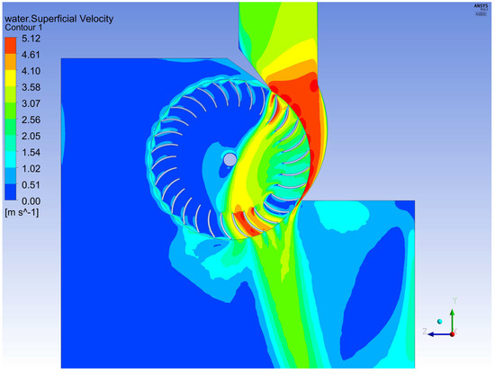
Figure 7.
Contours of mean water velocity in the single-nozzle turbine at maximum efficiency [ = 46 lps, H = 1.337 m, and = 199 RPM]. Note that the flow is confined to less than of the runner periphery.
4.2. Flow and Performance of Double-Nozzle Turbine
It was found that for the two nozzles was the same (199 RPM) as for the single-nozzle. As the identical nozzles were apart, the flow passing through the runner from each nozzle should be identical but similarly displaced, Figure 8. This symmetry was not enforced on the computations and some differences, particularly in the second stage flow, are apparent. At = 46 lps (per nozzle), the mean water velocity contours in the double-nozzle runner are slightly different than that of the single-nozzle, especially in the deflections between the the flow exiting the first-stage of Nozzle 1 and that entering the second stage of Nozzle 2, around the runner centre. As indicated by the circles in Figure 8, a portion of the flow exiting the first stage of nozzle 1 has been deflected by the flow entering the second stage of nozzle 2 and vice versa. The similar efficiencies of the single- and double-nozzle turbines imply that the flow deflection has little overall effect on the overall runner performance. However, in general, it can be argued that the mutual deflection of the two streams should be avoided. It is noted that the flow stream is narrowed by a factor of = 0.68 as it exits the first stage so that reducing this ratio may be effective. Further, can be decreased to avoid any mutual deflection of the flow streams in such a way that it would not reduce the maximum efficiency, for example as demonstrated below for part-load operations. On the other hand, the ability of the second stage of Nozzle 2 to accept flow from the first stage of Nozzle 1, and vice versa, can be viewed as an outcome of the highly desirable flexibility of the crossflow turbine concept in being the only hydro-turbine that has two stages. Since the present double-nozzle design maintains the efficiency of the single-nozzle, we have not attempted to reduce the mutual deflection.
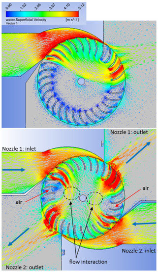
Figure 8.
Contours of mean water velocity vectors with a single-nozzle (a) and double-nozzle (b) operations at maximum efficiency [ = 46 lps per nozzle, H = 1.33 m and = 199 RPM].
The effect of the flow deflection on the runner performance can be examined by comparing the power extraction behaviour of the runner stages with single- and double-nozzle designs which was evaluated as described in [7,10]. As shown in Figure 9, the impact is reflected in the stage-performance as measured by the power extracted by each blade. Because of the slight asymmetry in the runner flow, the power was calculated for both nozzles but no substantial differences were apparent for the blades apart so only one set of symbols are shown. According to Adhikari and Wood [7], maximum efficiency requires conversion of head into kinetic energy in the nozzle, and the flow angles, e.g., and in the first stage of the runner, to equal the blade angles and respectively to avoid flow separation on the blades. is the same for both single- and double-nozzle runners, but the exit flow angle of the first stage has deviated considerably from the inner blade angle = 90 as a result of flow deflection in the regions indicated. Therefore, there is less power extraction in that region of the runner. It is important to note that the main difference is that the first stage performance of the double-nozzle runner had decreased whereas the second stage performance has increased. This is clearly the effect of flow deflection in the runner. Fortunately, for this particular turbine, the overall impact of this flow deflection was minimal and did not decrease the maximum efficiency. We conclude that this unoptimized crossflow turbine with two nozzles can achieve the same as with one.
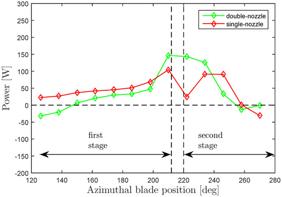
Figure 9.
Comparison of stage performances for the single- and double-nozzle turbines [ = 46 lps per nozzle, H = 1.33 m and = 199 RPM]. The negative power indicates that those blades lose power to the flow.
Part-load flow control is an essential design consideration. We used the slider mechanism of Sinagra et al. [12], which is a circular segment that can be rotated across the runner entry to reduce to be proportional to Q for . A key feature of the slider is that it maintains a constant as Q reduces [17], which should simplify the power electronics for the generator control. At , it is evident that the exit arc covers most of the runner periphery for the double-nozzle turbine and thus the angular range for the slider is small, especially when operating near per nozzle. We show in the Appendix A that the exit arc of the efficient 0.53 kW turbine is approximately half the size of the entry arc , which the simulations show is contiguous to the first stage. As such, for , an inflexible slider can control only a small percentage of . However, a retractable flexible slider can be designed to reduce for different Q.
The part-flow operation of the double-nozzle runner was computed for Q = 40, 30 and 20 lps with the same slider position, , as in the single-nozzle simulations of reference [17] and listed in Table 3. Figure 10 shows the part-flow efficiency. Desai [5] and Adhikari and Wood [7] determined that maximum efficiency occurs at RPM for . This compares with the value of 183 RPM from the analytical equation for , Equation (14) of reference [7], which also shows that slider position has no impact on as Q decreases. Therefore, simulations were conducted at RPM. Remarkably, at lps, there is no deflection between the flow streams in the runner as shown in Figure 11 and the performance was found the same as expected. Without the slider at the runner entry, and Q reduced to 40 lps from 46 lps, dropped significantly, but with the slider at lps, was found very close to the design condition. Similarly, using the slider, with Q reduced from 46 lps to 20 lps, which is about 43% of the design flow, the maximum efficiency of the double-nozzle runner dropped from 88% to about 85%. This demonstrates that the slider maintains high efficiency at considerably lower part-flow operations even when both nozzles are used for . These results are consistent with Sinagra et al. [12], who obtained similar performance of the slider in a single-nozzle turbine using RANS simulations.

Table 3.
Design and performance calculations at part-flow.
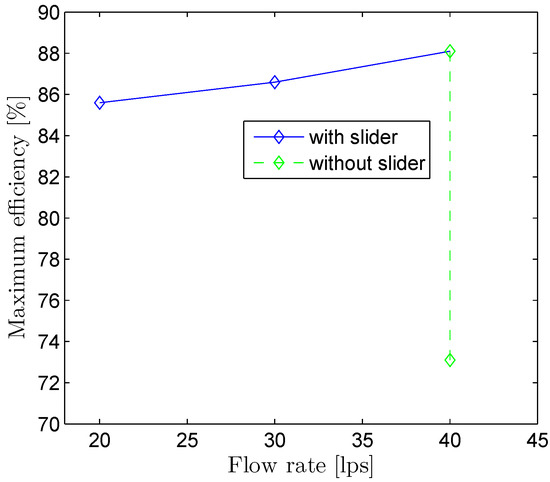
Figure 10.
Part-load performance of the slider control on the double-nozzle runner at maximum efficiency, H = 1.337 m and = 199 RPM.
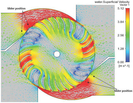
Figure 11.
Mean water velocity vectors at part-flow operation at maximum efficiency [Q = 40 lps, H = 1.337 m, = 199 RPM, and ]. It is noted that only the inlet portion of the slider in the nozzle section has been modelled. The end of the slider, labeled the “slider position” for and lps is shown for both nozzles.
At lps and without the slider, the total velocity at runner entry, , where and are the radial and tangential velocities respectively, dropped significantly from the ideal value of 5.12 m/s (=), Figure 12. This showed that H was not converted into kinetic energy. As a result, the efficiency decreased considerably. In contrast, the slider maintained close to 5.12 m/s, indicating that H is fully converted into kinetic energy. This demonstrates that the angular momentum flux at the runner entry has increased compared to the case without the slider, which is the reason for the improved efficiency.
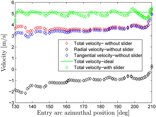
Figure 12.
Comparison of runner entry velocities with and without the slider at Q = 40 lps, H = 1.337 m, = 199 RPM, and .
The contours of the mean water velocity vectors in the double-nozzle runner at Q = 40 lps is shown in Figure 11; there is no deflection of the two flow streams as observed at . This indicates that a double-nozzle turbine designed with a smaller entry arc angle at is most likely to avoid deflection of the flow streams in the runner. Moreover, Figure 11 shows no flow separation on the blades at both stages, which is one of the important criteria for maximum efficiency. This is due to the fact that the entry flow angle , not shown here, is close to the outer blade angle . At very low part-flow operation, Q = 20 lps, the flow streams are well separated in the runner with no deflection as Figure 13. Also there is no flow separation on the blades.
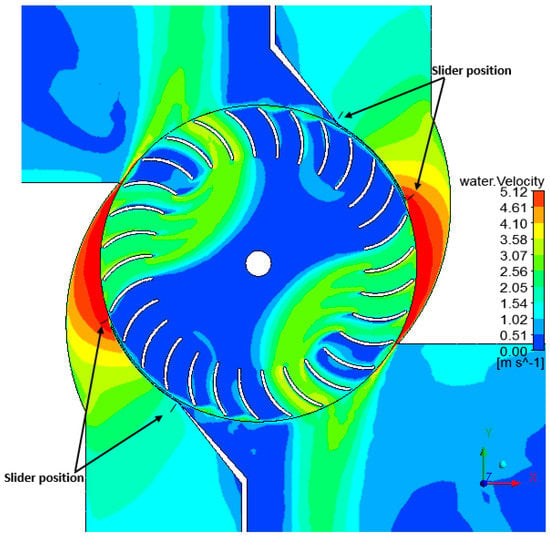
Figure 13.
Contours of mean water velocity at part-flow operation at maximum efficiency [Q = 20 lps, H = 1.337 m, = 199 RPM, and ]. The end of the slider, labeled the “slider position” for and lps is shown for both nozzles.
The design and performance calculations for all load cases are summarized in Table 3. Equation (A5) for the exit arc agreed well with all the computed results. Provided the reduction in by the slider preserves the conversion of H to kinetic energy in the nozzle, Equation (A5) is independent of Q. It is noteworthy that the first stage extraction increases as Q reduces, reaching a maximum of 88% at 20 lps. Increased first stage extraction, does not, however, directly relate to overall efficiency as demonstrated in Table 3. The results demonstrate the unique capacity of the crossflow runner to extract power in both stages.
5. Conclusions
We have presented the first computational analysis of a double-nozzle crossflow turbine based on a single-nozzle 0.53 kW turbine with a maximum efficiency of 88%. This turbine, one of the most efficient turbines available in the literature, was studied experimentally by [5] and numerically by [8,10]. They found that the runner entry and exit flow covered less than half the periphery of the runner: it is shown in the Appendix A that the exit arc should be smaller than the entry arc and the simulations indicated that the arcs are contiguous. This leaves room for a second nozzle which has not been used previously in crossflow turbines. We simply added a second nozzle to the 0.53 kW turbine without changing the nozzle or runner geometry.
A double-nozzle turbine provides a number of advantages over the single-nozzle, such as (1) increase in power density, (2) reduction in sources of vibration, mainly the non-uniform loading of runner blades, and (3) easier part-load control as one nozzle can be closed for low flow rates. The main conclusions drawn from the results of this study can be summarized as follows.
The maximum efficiency of the double-nozzle turbine was similar to that of the single-nozzle turbine which demonstrates the feasibility of using a second nozzle. We found that the double-nozzle runner had slightly higher efficiency at the design flow rate and similar efficiency at part-flow. This indicates that the power density of the turbine can be doubled by utilizing two nozzles instead of one while maintaining high efficiency. The main features of the flow in the nozzles and runner were documented. In the inner region of the double-nozzle runner at maximum flow rate, there was mutual deflection of the flow entering the second stage of the runner of the first nozzle and the flow stream exiting the first stage of the second nozzle. Remarkably, the overall impact of flow deflection on runner efficiency was negligible. In general, any potentially strong flow deflection may lead to significant loss in the runner efficiency, and thus should be further investigated in searching for higher efficiency.
We anticipate that the experimental studies on double-nozzle designs are needed to demonstrate the practical advantages and stimulate further studies on design improvement. It is noted that the double-nozzle design would not complicate the design and manufacturing, which can be done simply as for a single-nozzle turbine. On the other hand, the present calculations suggest that a crossflow turbine should not have more than two nozzles.
Author Contributions
R.A. and D.W. conceived, designed and analyzed the double-nozzle crossflow turbine. R.A. performed the RANS simulations using high performance computers provided by WestGrid Canada at the University of Calgary. Both authors synthesized the simulation results. D.W. supervised the research works reported in the paper.
Funding
This research received funding from the Schulich endowment to the Engineering Faculty.
Acknowledgments
The authors acknowledge the funding support from the Schulich Research Chair in Renewable Energy at the University of Calgary, Canada and the Schulich endowment to the Engineering Faculty. We also acknowledge WestGrid Canada for providing high-performance computers to perform flow simulations.
Conflicts of Interest
The authors declare no conflict of interest.
Abbreviations
The following abbreviations are used in this manuscript:
| CFD | Computational Fluid Dynamics |
| RANS | Reynolds-Averaged Navier-Stokes |
| 3D | Three-dimensional |
Appendix A. The Exit Arc of the Second Stage
It is assumed that and , the radial and tangential velocities respectively in a stationary co-ordinate system, are uniform over the whole entry arc at radius . For a runner rotating at rad/s, the entry flow angle for a rotating blade is
where the subscript “s” has been added to the velocities to denote first stage values. Assuming the velocities leaving the second stage are also uniform, conservation of mass requires
where is the “exit arc”, the angular extent of the exit flow and is the radial velocity leaving the exit arc. is positive towards the axis of rotation and is positive away from this axis. If it is assumed that is also the first stage blade inlet angle, then it must also be the second stage exit angle, so that
If it is further assumed that an efficient turbine has no angular momentum leaving the second stage, then Equation (A3) becomes
or
using Equation (A2). For the 0.53 kW turbine of Ref [5], m/s, m/s, m/s, so that or which is close to the value estimated from Figure 9. We conclude that the exit arc of an efficient crossflow turbine is approximately half the size of the entry arc. This simple analysis does not stipulate the origin of the exit arc. It is a further and essential result of the CFD analysis that the two stages are contiguous.
References
- Macmore, C.; Merryfield, F. The Banki water turbine. Eng. Exp. Stn. 1949, 25, 3–25. [Google Scholar]
- Khosrowpanah, S.; Fiuzat, A.; Albertson, M.L. Experimental study of crossflow turbine. J. Hydraul. Eng. 1988, 114, 299–314. [Google Scholar] [CrossRef]
- De Andrade, J.; Curiel, C.; Kenyery, F.; Aguillón, O.; Vásquez, A.; Asuaje, M. Numerical investigation of the internal flow in a Banki turbine. Int. J. Rotating Mach. 2011, 2011, 841214. [Google Scholar] [CrossRef]
- Acharya, N.; Kim, C.G.; Thapa, B.; Lee, Y.H. Numerical analysis and performance enhancement of a cross-flow hydro turbine. Renew. Energy 2015, 80, 819–826. [Google Scholar] [CrossRef]
- Desai, V.R. A Parametric Study of the Cross-Flow Turbine Performance. Ph.D. Thesis, Clemson University, Clemson, SC, USA, 1993. [Google Scholar]
- Totapally, H.G.; Aziz, N.M. Refinement of Cross-flow Turbine Design Parameters. J. Energy Eng. 1994, 120, 133–147. [Google Scholar] [CrossRef]
- Adhikari, R.; Wood, D. A new nozzle design methodology for high efficiency crossflow hydro turbines. Energy Sustain. Dev. 2017, 41, 139–148. [Google Scholar] [CrossRef]
- Adhikari, R.; Wood, D. The Design of High Efficiency Crossflow Hydro Turbines: A Review and Extension. Energies 2018, 11, 267. [Google Scholar] [CrossRef]
- Zhang, Z. Multi-jet Pelton Turbines. In Pelton Turbines; Springer: Berlin, Germany, 2016; pp. 243–246. [Google Scholar]
- Adhikari, R. Design Improvement of Crossflow Hydro Turbine. Ph.D. Thesis, University of Calgary, Calgary, AB, Canada, 2016. [Google Scholar]
- Choi, Y.D.; Lim, J.I.; Kim, Y.T.; Lee, Y.H. Performance and internal flow characteristics of a cross-flow hydro turbine by the shapes of nozzle and runner blade. J. Fluid Sci. Technol. 2008, 3, 398–409. [Google Scholar] [CrossRef]
- Sinagra, M.; Sammartano, V.; Aricò, C.; Collura, A.; Tucciarelli, T. Cross-Flow turbine design for variable operating conditions. Procedia Eng. 2014, 70, 1539–1548. [Google Scholar] [CrossRef]
- ANSYS. ANSYS Academic Research; ANSYS Inc.: Canonsburg, PA, USA, 2016. [Google Scholar]
- Brennen, C.E. Fundamentals of Multiphase Flow; Cambridge University Press: Cambridge, UK, 2005. [Google Scholar]
- Menter, F.R. Two-equation eddy-viscosity turbulence models for engineering applications. AIAA J. 1994, 32, 1598–1605. [Google Scholar] [CrossRef]
- Durgin, W.; Fay, W. Some fluid flow characteristics of a cross-flow type hydraulic turbine. In Small Hydro Power Fluid Machinery; ASME: New York, NY, USA, 1984; pp. 77–83. [Google Scholar]
- Adhikari, R.; Wood, D. Computational analysis of part-load flow control for crossflow hydro-turbines. Energy Sustain. Dev. 2018, 45, 38–45. [Google Scholar] [CrossRef]
© 2018 by the authors. Licensee MDPI, Basel, Switzerland. This article is an open access article distributed under the terms and conditions of the Creative Commons Attribution (CC BY) license (http://creativecommons.org/licenses/by/4.0/).