Safety Evaluation of Silicon Carbide and Zircaloy-4 Cladding during a Large-Break Loss-of-Coolant Accident †


Abstract
:1. Introduction
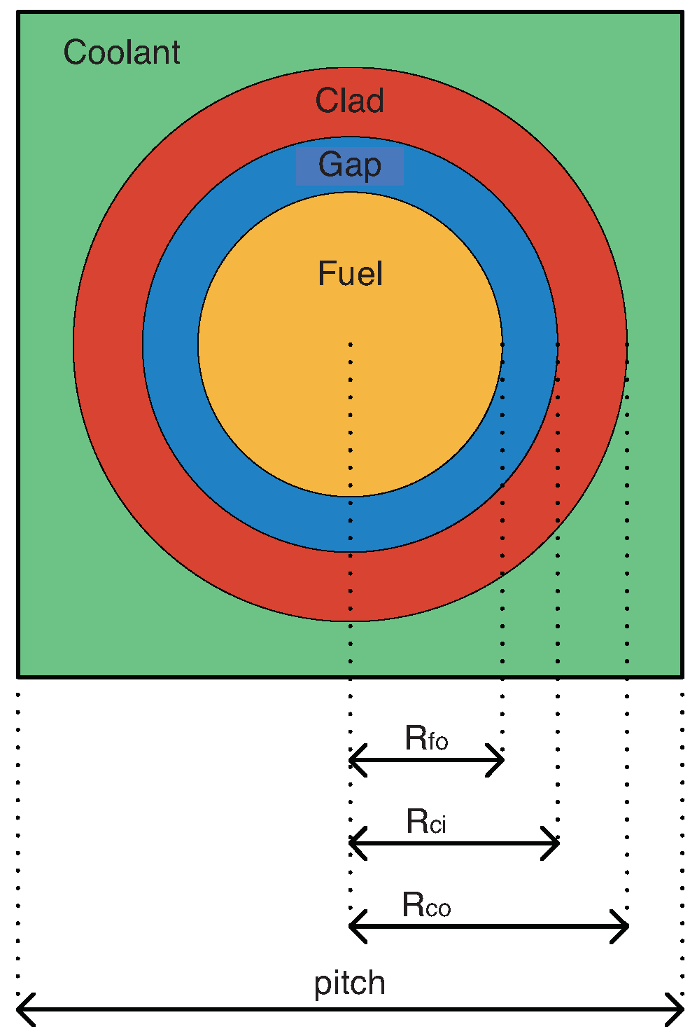
2. Fuel Design
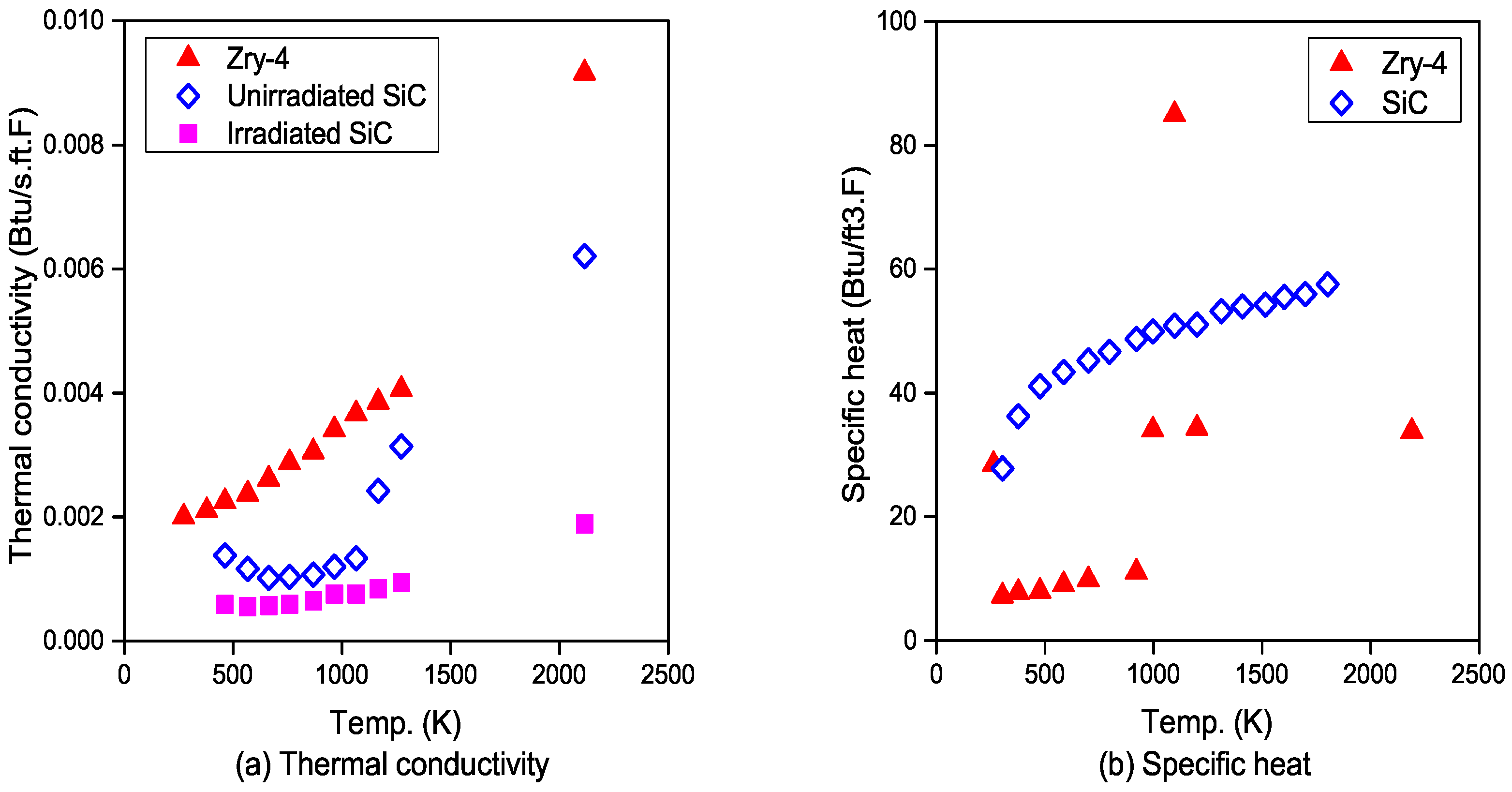
3. Material Properties
4. Fuel Rod Analysis
4.1. Methodology
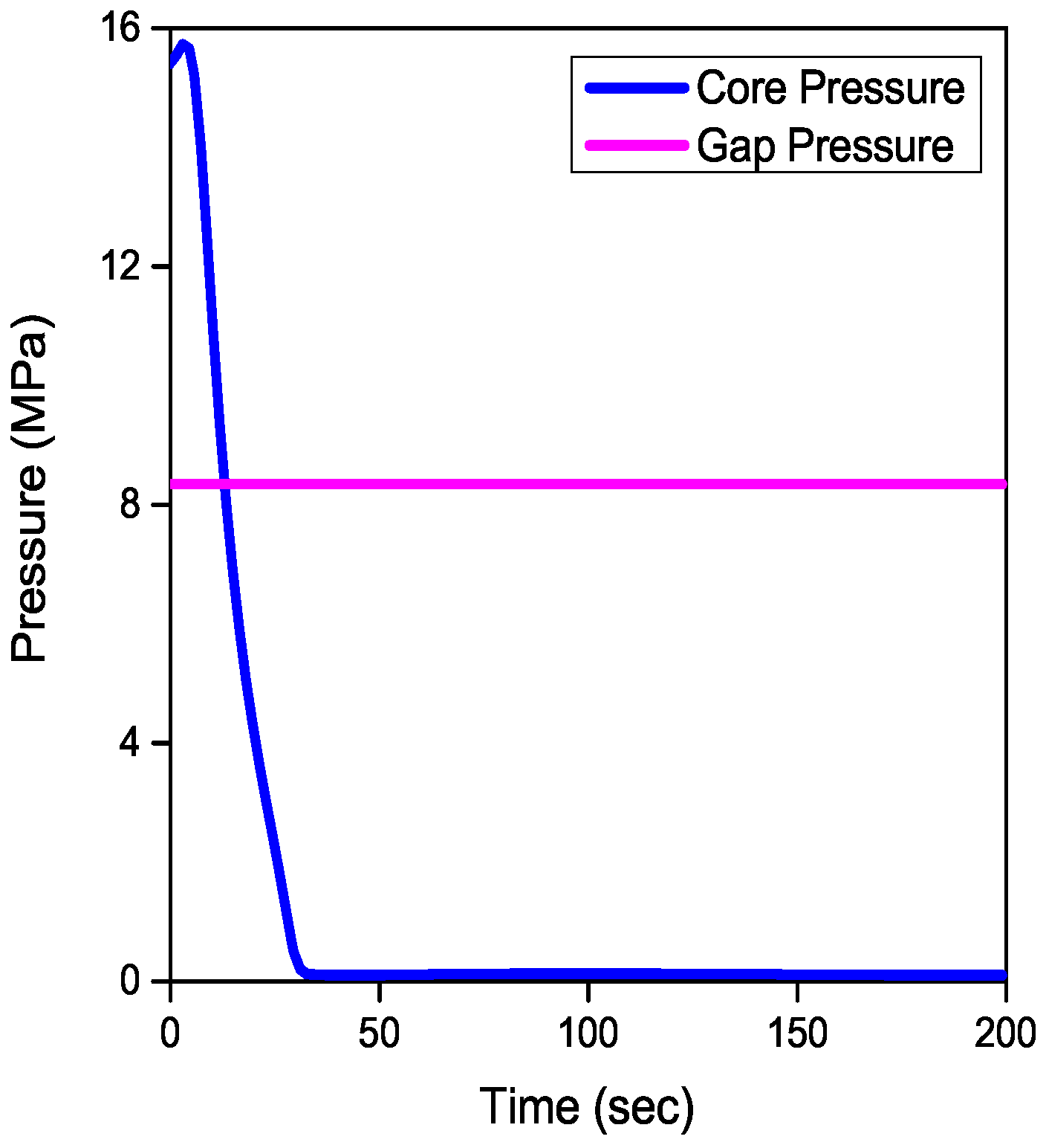
4.2. Boundary Conditions
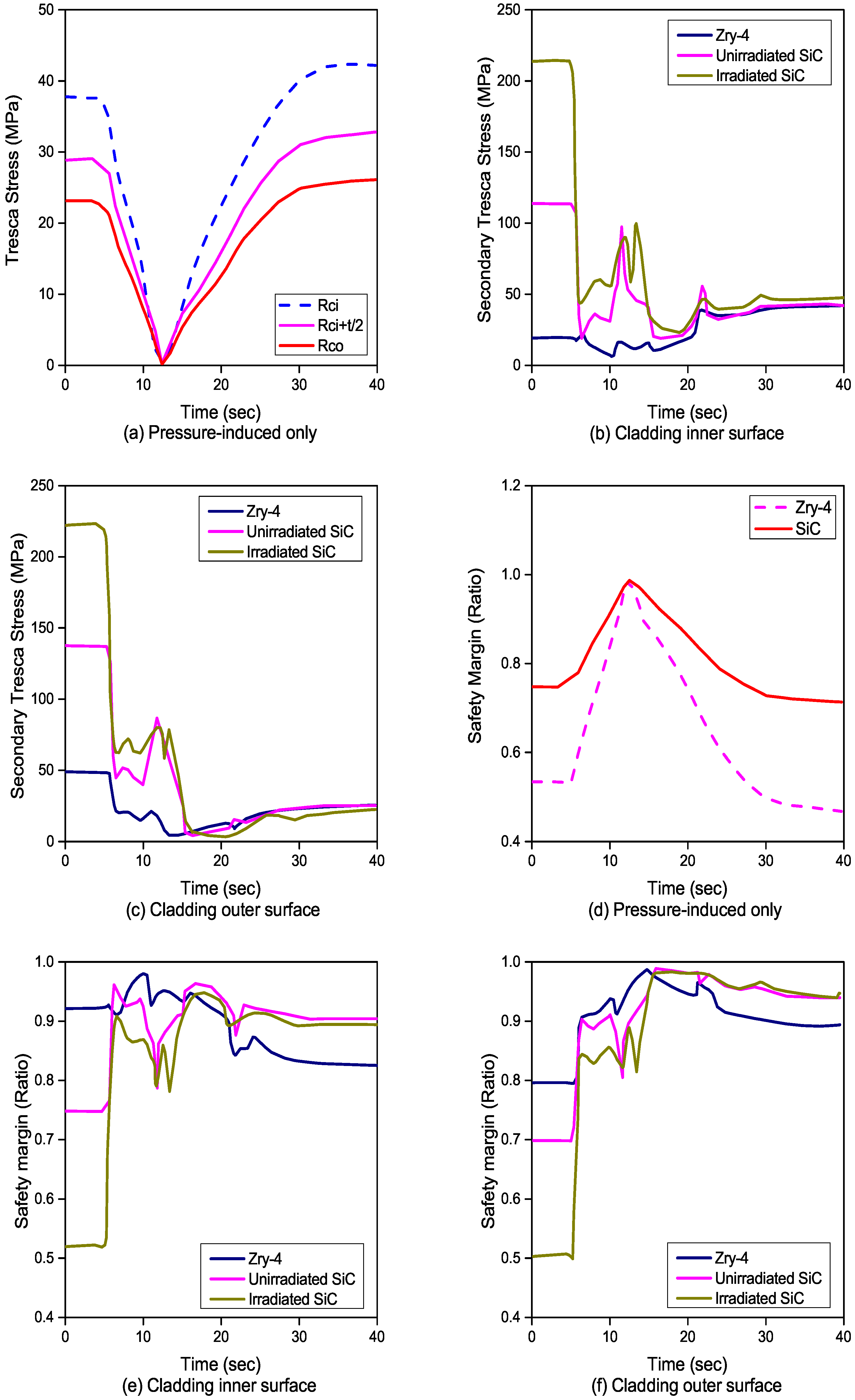
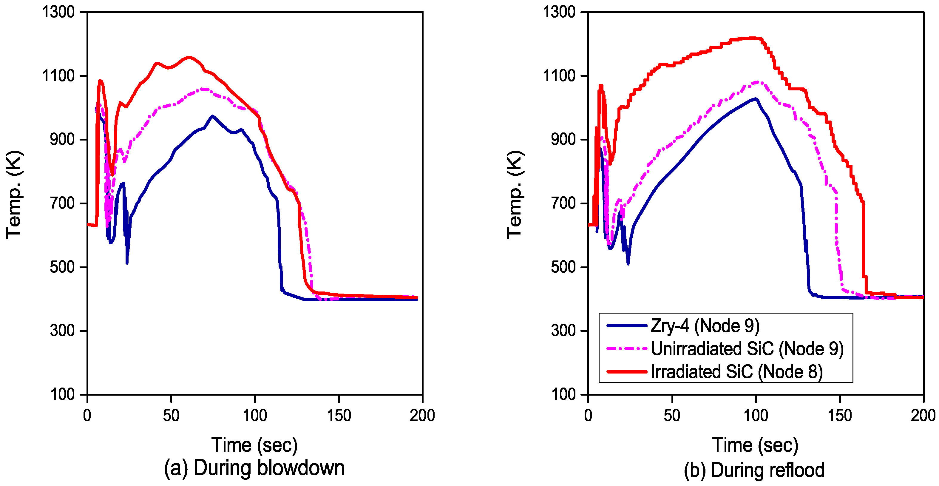
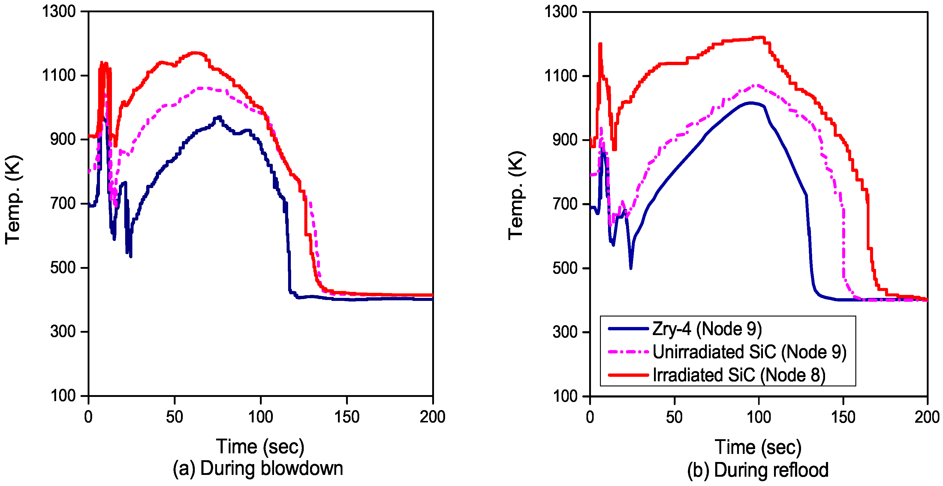
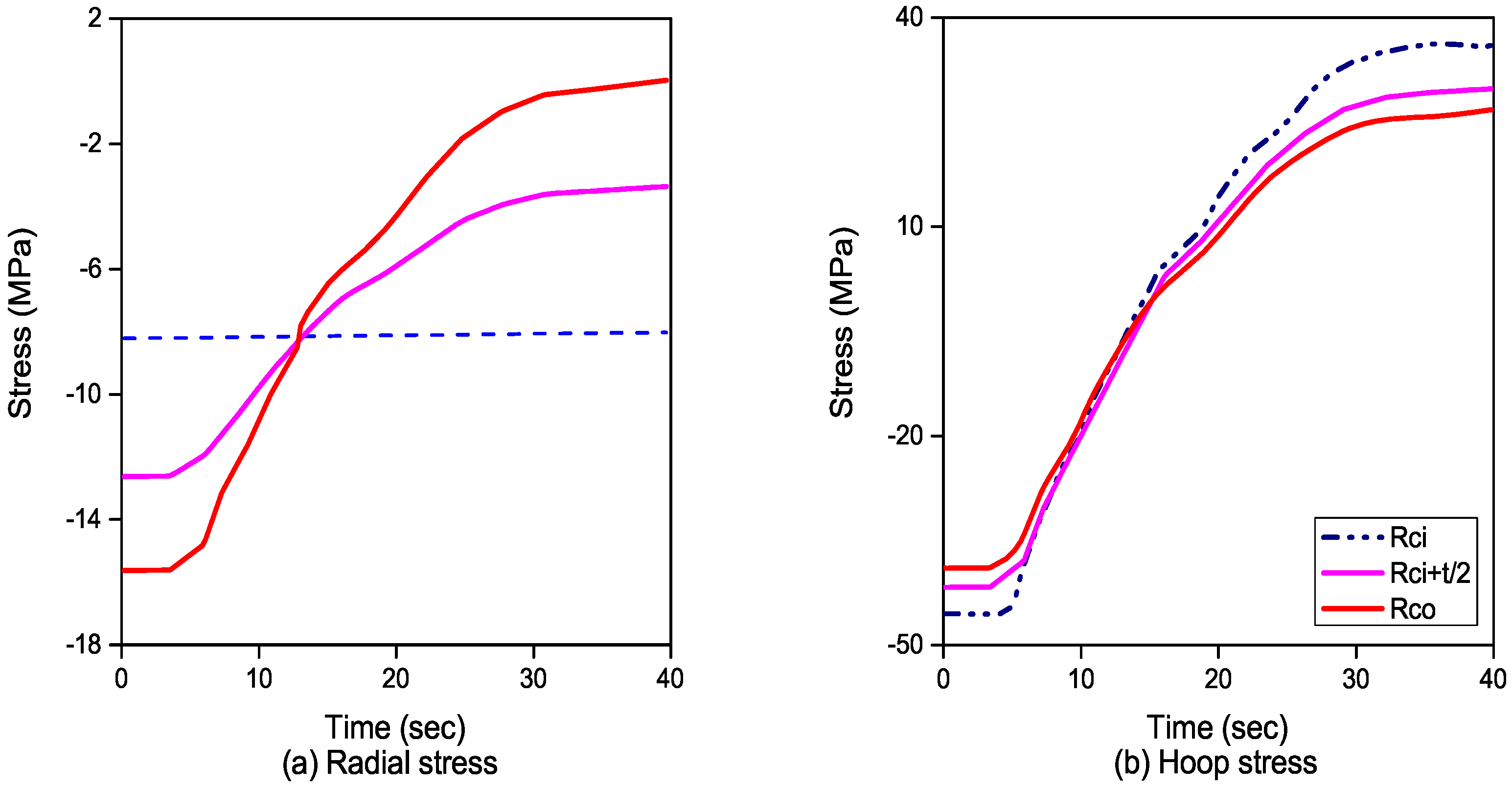
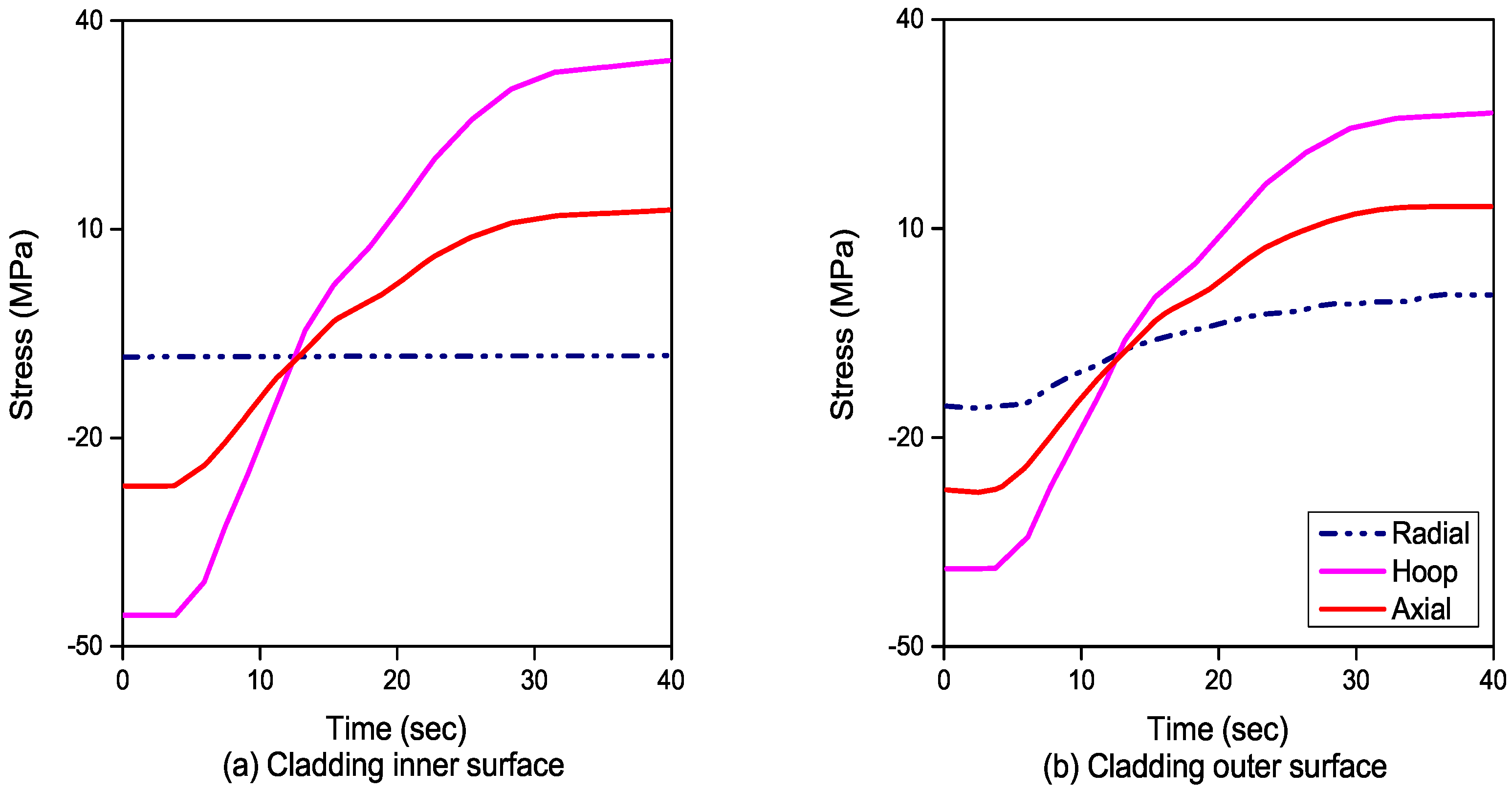
4.3. Results and Discussion
5. Conclusions
Author Contributions
Funding
Acknowledgments
Conflicts of Interest
References
- Snead, L.L.; Zinkle, S.J.; Steiner, D. Radiation Induced Microstructure and Mechanical Property Evolution of SiC/C/SiC Composite Materials. J. Nucl. Mater. 1992, 191–194 Pt A, 560–565. [Google Scholar] [CrossRef]
- Hollenberg, G.W.; Henager, C.G.; Youngblood, G.E.; Trimble, D.J.; Simonson, S.A.; Newsome, G.A.; Lewis, E. The Effect of Irradiation on the Stability and Properties of Monolithic Silicon Carbide and SiCf/SiC Composites up to 25 dpa. J. Nucl. Mater. 1995, 219, 70–86. [Google Scholar] [CrossRef]
- Rover, L.H.; Hopkins, G.R. Ceramic Materials for Fusion. Nucl. Technol. 1976, 29, 274–302. [Google Scholar] [CrossRef]
- Cozzo, C. SiC Cladding Thermal Conductivity Requirements for Normal Operation and LOCA Conditions. Prog. Nucl. Eng. 2018, 106, 278–283. [Google Scholar] [CrossRef]
- Lee, S.W.; Kim, H.T.; Bang, I.C. Performance Evaluation of UO2/Graphen Composite Fuel and SiC Cladding during LBLOCA using MARS-KS. Nucl. Egin. Des. 2013, 257, 139–145. [Google Scholar] [CrossRef]
- Yang, J.H.; Wang, J.R.; Lin, H.T.; Shin, C. LBLOCA Analysis for the Maanshan PWR Nuclear Power Plant Using Trace. Eng. Procedia 2012, 14, 292–297. [Google Scholar] [CrossRef]
- Bloom, E. The Challenge of Developing Structural Materials for Fusion Power Systems. J. Nucl. Mater. 1988, 263 Pt A, 7–17. [Google Scholar] [CrossRef]
- Price, R.J. Effects of Fast-Neutron Irradiation on Pyrolytic Silicon Carbide. J. Nucl. Mater. 1969, 33, 17–22. [Google Scholar] [CrossRef]
- Price, R.J. Properties of Silicon Carbide for Nuclear Fuel Particle Coatings. Nucl. Technol. 1977, 35, 320–336. [Google Scholar] [CrossRef]
- Katoh, Y.; Snead, L.L.; Henager, C.H., Jr.; Hasegawa, A.; Kohyama, A.; Riccardi, B.; Hegeman, H. Current Status and Critical Issues for Development of SiC Composites for Fusion Applications. J. Nucl. Mater. 2007, 367–370, 659–671. [Google Scholar] [CrossRef]
- Katoh, Y.; Snead, L.L.; Nozawa, T.; Kondo, S.; Busby, J.T. Thermophysical and Mechanical Properties of Near-Stoichiometric Fiber CVI SiC/SiC Composites After Neutron Irradiation at Elevated Temperatures. J. Nucl. Mater. 2010, 403, 48–61. [Google Scholar] [CrossRef]
- Senor, D.J.; Trimble, D.J.; Youngblood, G.E.; Newsome, G.A.; Moore, C.E.; Moods, J.J. Effects of Neutron Irradiation on Thermal Conductivity of SiC-Based Composites and Monolithic Ceramics. Fusion Technol. 1996, 30 Pt 2A, 943–955. [Google Scholar]
- Katoh, Y.; Ozawa, K.; Hinoki, T.; Choi, Y.; Snead, L.L.; Hasegawa, A. Mechanical Properties of Advanced SiC Fiber Composites Irradiated at Very High Temperatures. J. Nucl. Mater. 2011, 417, 416–420. [Google Scholar] [CrossRef]
- Katoh, Y.; Snead, L. Operating Temperature Window for SiC Ceramics and Composites for Fusion Energy Applications. Fusion Sci. Technol. 2009, 56 Pt 2, 1045–1052. [Google Scholar] [CrossRef]
- Feinroth, H. Silicon Carbide TRIPLEXTM Fuel Clad for Accident Resistance and Durability. In Proceedings of the 1st ICMST Conference, Kerala, India, 10–14 June 2012. [Google Scholar]
- Feng, L.; Zhu, F. Fuel Assembly Design for Supercritical Water-Cooled Reactor. J. Nucl. Eng. Radiat. Sci. 2016, 2, 011014. [Google Scholar]
- Ning, K.; Lu, K. Ion Irradiation Effect on Spark Plasma Sintered Silicon Carbide Ceramics with Nanostructured Ferritic Alloy Aid. J. Am. Ceram. Soc. 2018, 54, 605–612. [Google Scholar] [CrossRef]
- Snead, L.L.; Nozawa, T.; Ferraris, M.; Katho, Y.; Shinavski, R.; Sawan, M. Silicon Carbide Composites as Fusion Power Reactor Structural Matrials. J. Nucl. Mater. 2011, 417, 330–339. [Google Scholar] [CrossRef]
- Chang, W. Technical Data Sheet—Reactor Grade Zirconium Alloys for Nuclear Waste Disposal. Allegheny Technol. 2003. [Google Scholar]
- Tong, L.; Weisman, J. Thermal Analysis of Pressurized Water Reactors; American Nuclear Society: Cook County, IL, USA, 1996. [Google Scholar]
- Carpenter, D.M. Thermal Assessment of Innovative Fuel Designs for High Performance Light Water Reactors; MIT, Center for Advanced Nuclear Energy Systems: Cambridge, MA, USA, 2006. [Google Scholar]
- CoorsTek. Amazaing Solution: Advanced Silicon Carbide for Critical Components; F0401 8510-1024; CoorsTek Inc.: Golden, CO, USA, 2006. [Google Scholar]
- DiCarlo, J.A. High-Performance SiC/SiC Ceramic Composite Systems Developed for 1315 °C (2400 °F) Engine Component; NASA/TM-2004-212729; NASA: Washington, DC, USA, 2004.
- Kazimi, M.S. Lecture Notes and Problem Sets in Course 22.314; MIT, Center for Advanced Nuclear Energy Systems: Cambridge, MA, USA, 2006. [Google Scholar]
- Harvey, J.F. Pressure Vessel Design: Nuclear and Chemical Application; D Van Nostrand Company Inc.: Princeton, NJ, USA, 1963. [Google Scholar]


| Dimension | Unit | Value |
|---|---|---|
| Cladding thickness | mm | 0.57 |
| Cladding inside diameter | mm | 4.18 |
| Gap thickness | mm | 0.121 |
| Fuel-pellet diameter | mm | 8.19 |
| Fuel-rod diameter | mm | 9.5 |
| Active fuel height | m | 3.66 |
| U-235 enrichment | wt % | 2.6 |
| Fuel-rod pitch | mm | 12.6 |
| Channel effective flow area | 0.02458 | |
| Number of rod locations | number | 289 |
| Number of fuel rods | number | 264 |
| Zry-4 | SiC | |
|---|---|---|
| Coefficient of thermal expansion | 6 μm/m K | 3 μm/m K |
| Modulus of elasticity | 99.3 GPa | 410 GPa |
| Poisson’s ratio | 0.37 | 0.21 |
| Yield strength | 170 MPa | 450 MPa |
| Ultimate tensile strength | 241 MPa | 450 MPa |
| Parameters | Desired | Simulated |
|---|---|---|
| Core power (MWth) | 3479.2 | 3479.2 |
| Pressurizer pressure (bar) | 155.1 | 155.1 |
| Cold leg temperature (K) | 564.85 | 566.61 |
| Hot leg temperature (K) | 599.25 | 598.71 |
| Total loop flow (kg/s) | 18,630.0 | 18,714.3 |
| Effective core flow (kg/s) | 17,700.0 | 17,857.2 |
| Bypass flow fraction (%) | 5.00 | 4.58 |
| SG secondary pressure (bar) | 58.0 | 61.8 |
© 2018 by the authors. Licensee MDPI, Basel, Switzerland. This article is an open access article distributed under the terms and conditions of the Creative Commons Attribution (CC BY) license (http://creativecommons.org/licenses/by/4.0/).
Share and Cite
Ahn, K.; Joo, K.; Park, S.-P. Safety Evaluation of Silicon Carbide and Zircaloy-4 Cladding during a Large-Break Loss-of-Coolant Accident. Energies 2018, 11, 3324. https://doi.org/10.3390/en11123324
Ahn K, Joo K, Park S-P. Safety Evaluation of Silicon Carbide and Zircaloy-4 Cladding during a Large-Break Loss-of-Coolant Accident. Energies. 2018; 11(12):3324. https://doi.org/10.3390/en11123324
Chicago/Turabian StyleAhn, Kwangwon, Kyohun Joo, and Sung-Pil Park. 2018. "Safety Evaluation of Silicon Carbide and Zircaloy-4 Cladding during a Large-Break Loss-of-Coolant Accident" Energies 11, no. 12: 3324. https://doi.org/10.3390/en11123324
APA StyleAhn, K., Joo, K., & Park, S.-P. (2018). Safety Evaluation of Silicon Carbide and Zircaloy-4 Cladding during a Large-Break Loss-of-Coolant Accident. Energies, 11(12), 3324. https://doi.org/10.3390/en11123324