1. Introduction
Research of the physical and technical basis of sources for the generation of super-power electromagnetic fields and current pulses with the help of explosion-magnetic generators (EMG), outlined in classical works [
1,
2], found a continuation in new problems for plasma loads. Among the common problems we can note the following: pulsed plasma accelerator (PPA) [
3,
4,
5], plasma focus [
6], modeling and study of the dynamics of plasma jets in the ionosphere [
7], high-current plasma interrupters [
8,
9], the generation of X-ray radiation [
10], and studies of erosion of metal samples under the influence of intense plasma flows created by the PPA [
11]. All of these areas have special requirements for the energy source, forming a pulsed current to generate a plasma flow with the necessary parameters.
Capacitive storage devices are traditionally used as energy sources in these tasks. They are very practical to use, but they do not match well with plasma loads, especially in the mega-ampere range of plasma accelerator currents. This is due to the feature of changing the power source during operation of the PPA [
5]. The rapid acceleration of the plasma leads to a significant change in the inductance of the load, which requires an increase in the power supply to maintain large current amplitude. Capacitive storage devices have the highest power at the highest voltage, and therefore in the process of operation on the PPA only their power falls. However, EMG have their maximum power at the end of their operations, which allows them to keep and even increase their current in the load despite a significant change in the inductance of the load. This EMG feature allows effective matching with the non-linear load of plasma, and this will be confirmed in this article also.
The experience of using an alternative source for PPA, based on EMG, is described in article [
5]. As is known from the early estimates [
12], the highest efficiency of energy transfer from the HMG directly to the inductive load is when the load inductance is significantly less than the generator inductance. However, both the inductance of the generator and the inductance of the load change during operation on the plasma load. Moreover, if the inductance of the generator is reduced and we can control the law of its output at the design stage, the plasma load increases nonlinearly. In this article, we propose a mathematical model that allows one to predict the current in the load at the design stage of the EMG. The model takes into account the output of the EMG inductance to a specific load for the selected electrical circuit. The model calculates the dynamics of inductance change in EMG, taking into account changes in the geometry of both the generator’s coil and the liner. A liner means a tube, usually made of copper, filled with an explosive. With the end explosion of the charge, the liner expands in the form of a cone, cutting off parts of the generator coil over time. As the liner contacts move along the EMG spiral, the magnetic flux is compressed and displaced into the load. Because the change in the inductance of the plasma load is nonlinear, the role of experimental studies is very important. The paper [
5] presents the results of research and development of the device for forming a current pulse consisting of a solid-state circuit breaker and explosive breaker keys with an adjustable delay of their operation. The perspectives of such a scheme due to the wide possibilities to manage the keys and the movement of the liner were noted as well. In the present work, research was continued, and as a result the value of the supplied energy from the EMG to the load reached more than 500 kJ. The proposed design of the generator, optimized for specific load, allows us to effectively pump the magnetic flux into the plasma load. This avoids premature falling of the current amplitude. The idea of the operation of the device built into the EMG design is to connect the load circuit and disconnect the EMG circuit with an adjustable delay. Selecting the appropriate delay allows one to control the residual inductance of the EMG at the switching moment and optimize the shape of the current pulse in the load. The optimization of the device operation consists in the pre-selected mode of change (output) of the inductance of the EMG and the choice of the time diagram for the solid-state circuit closer and the explosive breaker. Generator residual inductance output is the main phase of the power supply to the load. This phase provides an increase in electrical power in the load circuit at a significant change in its inductance. In addition, to increase the power of the generator, the copper liner was equipped with a new type of explosives, which narrowed the front of the current pulse.
The article presents the comparative oscillograms of currents and voltages for a pulsed source based on capacitive storage and inductive pulse sources based on EMG when PPA operates in two modes. The modes were different by the connection time of the load. A series of experiments to control the shape of the output pulse of the current EMG and the matching of the latter with the work of a specific plasma load was carried out. Modes of efficient energy transfer to the load have been obtained.
The principles of operation of the helical EMG and PPA are not considered in this article. Here, we consider EMG as a pulsed-current source based on nonlinear inductive energy storage, and PPA as a nonlinear load for EMG with a growing inductance during operation, which is typical for a wide class of plasma loads.
The structure of the article is as follows. After the introduction, a chapter with the results of the study of the work of the plasma accelerator with a capacitive power source is presented. Then, the results of modeling and experimental studies of an alternative source based on an explosion-magnetic generator with built-in devices for current-pulse formation are presented. After that, the modes of operation of this device were considered. In conclusion, the main results of the research are shortly presented, the mode of the most efficient power supply of PPA is noted, and the methods of application of the developed EMG are indicated.
2. Experimental Study of the PPA Work with Use of Capacitive Power Source
The scheme of direct connection of the capacitive storage to the plasma accelerator is a typical LCR circuit with a switch-solid-state discharger. The parameters of applied capacitors are as follows: capacity is 1 mF, and the operating voltage is up to 25 kV. The voltage was measured by means of a divider built into the input collector of the load; the current was measured by the Rogowski coil built into the switching discharger.
Characteristic oscillograms of the PPA from the capacitor power source are shown in
Figure 1. The current and voltage distributions on the load and the change in load inductance are plotted on the same time scale. As can be seen from the presented oscillograms, when the current reaches a value of about 1.5–2 MA, the load inductance begins to increase sharply, which leads to a significant increase in the voltage to 20 kV or more. The time voltage on the capacitor battery does not exceed 10 kV. It is obvious that the residual voltage of the battery is not able to provide the discharge circuit with the magnetic flux necessary to maintain the current. The results of the described situation are in sharp contrast to the current amplitude when the load is rebuilt and the deviation of the current waveform from the sinusoidal shape. Actually, the experimental task is to achieve the maximum value of the current before the sharp increase of the system inductance, after which the parasitic inductance of the circuit works as energy storage. It is not possible to significantly increase or even maintain the current in the system with a capacitor battery after this moment.
Thus, when PPA works with use of capacitive power source and its inductance increases sharply, this leads to the appearance of “features” on the current and voltage oscillograms. These features on the oscillograms at the beginning and at the maximum current are what distinguishes them from the classical distributions when the capacitor is operating at a constant inductive load. One of the main parameters that determine the efficiency of such systems is the maximum achievable current amplitude before the appearance of this feature, after which the current in the system falls. In this scheme, with about 270 kJ stored in the capacitive energy storage, about 25% of the energy was transferred to the load.
3. Operation of PPA with Use EMG Power Source
The equivalent electric circuit for operation of EMG on the load is presented in
Figure 2. The initial magnetic flux in the generator is powered from the initial energy source E
0, representing the capacitive storage. The energy of explosives goes to the expansion of the liner, which in turn compresses the magnetic flux inside the helical EMG.
The main parameters of the circuit are: the initial energy E0, the initial and residual inductance of the EMG, ohmic resistance in the EMG circuit and the circuit of the breaker, parasitic inductance in the circuit of the circuit and the load circuit, and inductance load. Parasitic inductance is determined by the leading cables, and it should be minimized. This scheme also corresponds to experimental setup when the EMG operates on a single accelerator. The scheme demonstrates the location of the main elements of the circuit, including the primary current sensors—Rogowski coils (RC), the voltage divider (VD), and magnetic probes (MP).
Switching device for the current-pulse formation in the load includes the following keys: the solid-state circuit closer (Sc) and the assembly with explosive breaker (Sb). The switching keys do not work at the same time. Sb is triggered with a delay with respect to Sc in accordance with the time diagram. This delay determines the current in the load and the residual inductance of EMG in the circuit after the switching.
Capacitive storage of 130 μF with voltage up to 30 kV was used as a source of initial energy. EMG initial inductance was approximately 10 μH. Currents in the experiments were calculated by numerical integration of data from Rogowski coils while taking into account the sensitivity of each coil. The recording of signals from the Rogowski coils is made on oscilloscopes PICOSCOPE 5000 series. Voltage measurements were made using voltage dividers DV (1:3000), designed for pulse signals.
3.1. Results of Numerical Modeling of the Current Pulse with EMG Source
For theoretical estimates, a simplified electrical circuit of the EMG operation on a variable load was taken, which is shown in
Figure 2.
The calculation of the generator is performed in two stages. First, the calculation of the dynamics of the inductance output of the EMG was performed with use the open numerical complex of Finite Element Method Magnetics (FEMM 4.2). This complex allows two-dimensional, steady-state calculations of magnetic fields for the specified design of the EMG entered into the program at a constant frequency by the finite element method. The possibility of using scripts for geometry transformation made it possible to calculate the high-frequency inductance for each position of the liner. The dynamics of the liner movement was set manually. The final dynamics of the inductance output is shown
Figure 3 and used in the calculation of the electrical circuit of the generator to the load.
Before connecting the load, the EMG is shorted through the explosive breaker S
b; the current goes only along one circuit—1, and it greatly simplifies the equations for its calculation. After connecting the load, the current flows through both circuits
Ib and
IL, as long as the resistance of the explosive breaker dynamically changes in the first circuit and it is triggered. Dynamics of changes of this resistance determine the process of switching current to the load. The dependence of the breaker resistance on time was approximated from experimental data by a function of the following form:
The Equation (1) describes well the experimentally measured resistance dynamics of the developed breaker in the EMG circuit. It agrees with experimental data with high accuracy at the coefficient’s selection, as seen in
Figure 4. However, it should be noted that at high cut-off currents (2.5–3 MA for our design), when the aluminum foil in the explosive breaker is heated by the EMG current to melting temperatures, this function becomes inadequate. In this case, an increase in the geometric dimensions of the explosive breaker is required. Nevertheless, this function of resistance increases the explosive breaker (see
Figure 4), and the dynamics of the inductance output (see
Figure 3) allow carrying out of a package of preliminary calculations to determine the output parameters of the EMG current. These calculations were carried out only on the concentrated load. The equations describing the dynamics of current switching to the load are given below:
in which
f is the coefficient of EMG perfection, and
, which reflects the degree of magnetic flux saving during EMG operation. The typical value of
f for the EMG is 0.85, [
2].
Iemg is the current through the EMG,
Ib is the current through the circuit breaker,
IL is the current through the load, and
Lemg is inductance of EMG.
The system (2) can be reduced to the following system of differential Equations (3) suitable for the calculation of the current switching process:
The constructed model allows varying the parameters of the load, EMG, and the explosive breaker in a wide range, which is necessary to optimize the design in order to obtain the necessary current pulse in the load. The specific characteristics of various subassemblies are specified according to the experimental data. The results of calculations of the output parameters of the current pulse of EMG, of the load, and of the load voltage for the developed designs are presented below in
Figure 5.
The presented calculations refer to a constant inductance of the load of 50 nH, while the plasma load is variable to a large extent, and at the end of the accelerator operation, its inductance becomes at least doubled. This leads to a change in the voltage shape, which depends on the dynamics of the inductance in the load. This calculation allows us to reliably estimate the dependences, especially for currents, which have been confirmed experimentally many times. That is why this model is convenient to use for verification of various designs in order to obtain an adequate representation of the current pulse in the load, when the input parameters change in a wide range.
3.2. Results of Experimental Studies with Use EMG Power Source
To maintain the current rise in the load, it is necessary to pump the magnetic flux at an increasing rate, which requires increasing voltage and power of the power source. It is obvious that the capacitive storage does not have this characteristic. The EMG with a special current-pulse-forming device was developed to solve this problem. General view of the EMG design is shown in
Figure 6a,b.
This version of the EMG is a classic helical generator combined with two switches in one design. The principle of operation of the developed design is as follows. In the first phase of operation of the device, the spiral coil of EMG (element #3,
Figure 6a) is powered by initial energy source E
0 and the initial magnetic flux is formed. After that, the main charge of the liner is detonated, and the EMG most of the time works on the explosive breaker (element #5) in a short-circuited mode, converting the explosive energy into electrical energy. During the next stage, the load is connected in parallel with the circuit breaker using a solid-state circuit closer (element #4). After connecting the load, the explosive breaker (5) is activated with delay and switches the main current to the load. Selection of residual inductance of EMG is the final stage of the described design. Depending on the selected mode of synchronization, inductance was from 50 to 500 nH at the time of operation start of the explosive breaker.
The increasing power at the working on the load in the final stage is a key aspect of the described concept of operation of the EMG, which is provided by the continually-increasing derivative of the inductance (). In addition, it is important to note that this design has considerable flexibility, because it has many adjustable parameters. These parameters include the moments of connection of the load and the operation of the explosive breaker, and the residual inductance and its sampling time. The general time diagram of the EMG is determined by the speed of expansion of the liner, which is regulated by the type of used explosives and the geometry of the liner. The moment of the load connection is determined by the contactor position. The moment of explosive breaker operation is determined by its own response time and the detonation line delay between the main charge of the explosive and the charge in the breaker. The time of the residual inductance transformation of generator at the last stage of work is regulated by adjusting the angle of the spiral slope of EMG in the last section to the angle of the liner opening and the liner speed. The detonation of explosive is carried out from one detonator and does not require additional detonation lines to synchronize the switching devices. The variability of the generator parameters allows optimizing EMG operation for a wide range of non-linear plasma loads. The developed design of the generator is equipped with a special coaxial current output of energy. It allows use of explosive protective cameras for EMG, while the load is located outside the chamber and can be fully saved.
A key moment in the development of design EMG was the need to hold a lot of charge inside the liner is in the range of 5–6 kg, because the explosion chamber “Titan”, with a maximum permissible weight of 8 kg, was used in experiments in laboratory conditions. Copper liners with diameters from 90 to 95 mm with charges made from bulk explosives were used in a preliminary series of experiments. Also, two types of the main spiral of the EMG were used. The spiral with a diameter of 200 mm was used in the first startups for testing the design of the generator. After testing the design of the first series generators, the transition to more powerful ones with a spiral diameter of up to 300 mm was carried out. The used types of charges provided the transverse speed of the liner from 1 to 1.5 km/s, which corresponds to the angle (from the axis) of liner opening from 7 to 9 degrees. These speeds allowed reaching of the sampling time of generator residual inductance at the level of 10–18 µs. Another advantage of the use of EMG is their constructive ability to minimize the parasitic inductance between the current source and the load due to the use of the parallel circuit of the load. Electrical scheme of EMG with a load in the form of two PPA connected in parallel is shown in
Figure 7.
Both loads are connected in parallel through the collector. Current collector in this case is an element of the electrical circuit, which is used to connect the current output of the EMG with the load by means of coaxial cables. This design allows reduction of the parasitic inductance in the circuit and increase of the power source without increasing its dimensions.
Two main modes of operation of the device for the current-pulse formation of the EMG in the load in the form of PPA were investigated during the experimental series. The modes differed mainly by the synchronization of the switching assemblies of the generator, Sc, and Sb.
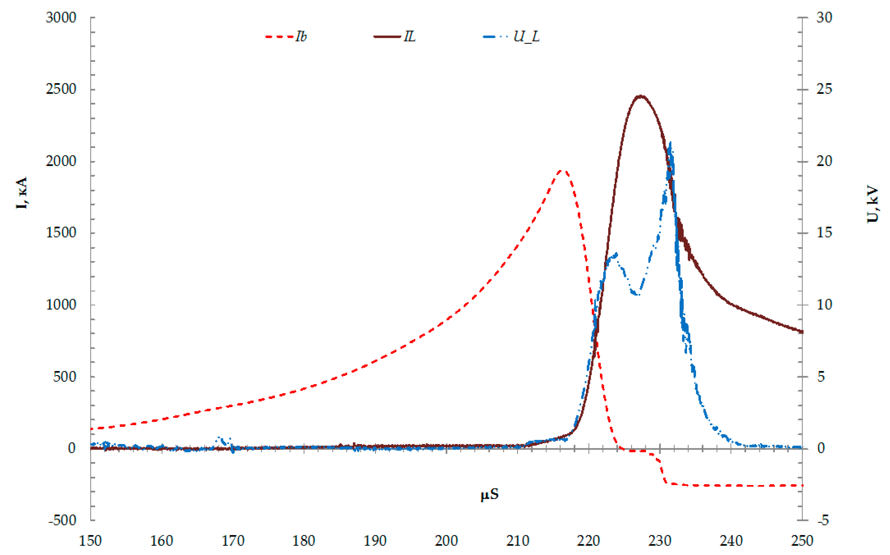
3.2.1. The First Operation Mode of the Current-Pulse Formation Devices
The first mode is characterized by later operation of the explosive breaker with respect to the circuit closer and, accordingly, the larger sample of the main inductance of the EMG. In this synchronization mode, the current is switched to the load at a sufficiently high current >2 MA, and the residual inductance of the EMG after switching is practically absent. In the described mode, the residual inductance transformation increases the current in the load after switching slightly.
Illustration of the first mode in the form of current distributions in EMG, PPA, and voltage on PPA is presented in
Figure 8. It corresponds to the scheme in
Figure 1.
In fact, this mode repeats the task of fast acceleration of the current in the capacitor battery, but it significantly increases the derivative of the current and the current in the load. The time of current switching in the experiments was 3–4 µs at the maximum current amplitude in the load of ~2.5 MA. For comparison, the current is increased to 1.8–1.9 MA for about 10 µs with use the capacitor power source. Reducing the parasitic inductance of the system plays a significant role in increasing the derivative current in the load. Note that the parasitic inductance of the bus arrangement and the switching discharger is at the level of 35–40 nH in the system with a capacitor power source, while the passive (parasitic) inductance can be kept at the level of 15–20 nH in the system with EMG. Comparison of experimental and calculated results (see
Figure 1) showed that the calculations correctly describe the processes; the accuracy of the coincidence values is about 15%–20%.
3.2.2. The Second Operation Mode of the Current-Pulse Formation Devices
The second mode of EMG operation of the developed design is the mode with an explicit displacement of the residual magnetic flux into the load after switching-over the current into the load. This mode was made according to the scheme with connected of two accelerators. In this mode, the load on the explosive breaker is significantly reduced due to the fact that the switching is at a current of ~1–1.5 MA. After switching, the residual inductance of EMG remains significant (about 180–200 nH) and its sample takes 5–6 µs. At the same time, it is possible to match the process of pumping the residual magnetic flux into the load with the dynamics of increasing its inductance. The experimental results are presented in
Figure 9 and
Figure 10.
The oscillograms of current and voltage pulses during the operation of the EMG on two plasma accelerators (PA), connected in parallel, are shown in
Figure 9, and correspond to the schematic diagram in
Figure 7. The voltages were measured on the current collectors of each PPA. A series of experiments allowed one to sequentially choose the best conditions for matching the time diagram of the EMG with the dynamics of the load. In this mode, the current rise in the load is observed at the transformation of the residual inductance of EMG after switching the current to the load. The maximum current reaches of 3.8 MA. Moreover, the main phase of PPA operation takes place with the increasing power of EMG. The peak power value is 27 GW. The energy transmitted from the EMG to the load reached 0.55 MJ, as shown in
Figure 10.
