Article

Reservoir Permeability Evolution during the Process of CO2-Enhanced Coalbed Methane Recovery

1
Shandong Provincial Key Laboratory of Civil Engineering Disaster Prevention and Mitigation, Shandong University of Science and Technology, Qingdao 266590, China
2
State Key Laboratory Breeding Base for Mine Disaster Prevention and Control, Shandong University of Science and Technology, Qingdao 266590, China
3
Geotechnical and Structural Engineering Research Center, Shandong University, Jinan 250061, China
*
Authors to whom correspondence should be addressed.
Energies 2018, 11(11), 2996; https://doi.org/10.3390/en11112996
Submission received: 13 September 2018 / Revised: 10 October 2018 / Accepted: 29 October 2018 / Published: 1 November 2018

Abstract

:
In this study, we have built a dual porosity/permeability model through accurately expressing the volumetric strain of matrix and fracture from a three-dimensional method which aims to reveal the reservoir permeability evolution during the process of CO2-enhanced coalbed methane (CO2-ECBM) recovery. This model has accommodated the key competing processes of mechanical deformation and adsorption/desorption induced swelling/shrinkage, and it also considered the effect of fracture aperture and effective stress difference between each medium (fracture and matrix). We then numerically solve the permeability model using a group of multi-field coupling equations with the finite element method (FEM) to understand how permeability evolves temporally and spatially. We further conduct multifaceted analyses to reveal that permeability evolution near the wells is the most dramatic. This study shows that the farther away from the well, the gentler the evolution of permeability. The evolution of reservoir permeability near the injection well (IW) and the production well (PW) are very different, due to the combined effects of effective stress changes and gas adsorption and desorption. Furthermore, adsorption is the main controlling factor for the change of permeability for regions near the IW, while the change in effective stress is the main cause for the change in permeability near the PW. Increasing the injection pressure of CO2 will cause the reservoir permeability to evolve more quickly and dynamically.

1. Introduction

Coalbed methane (CBM) recovery from coal seams, as an unconventional resource, is a growing contributor to the energy supply for the energy-hungry world [1,2,3]. Carbon dioxide (CO2) geological storage through reducing the risk of CO2 migration to the surface is becoming an important method for effective control of greenhouse gas [4,5,6,7]. CO2-enhanced coalbed methane (CO2-ECBM) recovery is a technology that increases CBM production while controlling greenhouse gas by injecting CO2 into CBM reservoirs, which has already been applied in several field projects [8,9,10]. At the end of 20th century, a company named Amoco first carried out pilot field of ECBM recovery in the San Juan basin of the United States [11]. The results showed that methane (CH4) production is increased by five times as compared to conventional production methods [9,11]. Then, a series of field ECBM recovery pilot projects have been executed in North America, Poland, China, and Japan [10,11,12]. The implementation of these projects has proved the feasibility of the CO2-ECBM recovery technology.
The CBM reservoir can be considered as a typical fractured sorbing media where the majority of gas is stored in the matrix in the adsorbed state and only free gas exists in fractures [13,14,15]. Hence, during the process of CO2-ECBM recovery, mass transfer between the coal matrix and fractures occurs in the reservoir. Early laboratory studies have demonstrated that that coal can adsorb approximately twice as much CO2 (in mole) by volume as CH4 [12]. As a result, the competitive adsorption capacity will help CO2 replace CH4 adsorbed in the coal matrix during the process of CO2-ECBM. A multi-scale schematic to characterize the CO2-ECBM recovery process is shown in Figure 1. However, one of the technical challenge is that the process of adsorption/desorption of the binary gas will result in the swelling/shrinkage of the coal matrix [16,17,18,19]. Another unavoidable fact is that the pore pressure of the coal seam will change during the process of CO2-ECBM recovery which can directly affect the effective stress [20,21,22]. These two factors will cause the pore volume and fracture aperture to change dynamically, and ultimately result in the dynamic evolution of reservoir porosity and permeability, which are the key parameters for predicting CBM production and CO2 storage.
Some previous studies have been carried out mainly focusing on the dynamic porosity/permeability of fractured sorbing media like the CBM reservoir to determine the complex and dynamic of evolution characteristics of reservoir porosity/permeability. The following references are representative studies conducted in this context. Seidle et al. [23] explored the relationship between permeability and horizontal stress under uniaxial conditions using the matchstick geometry model. Seidle and Huitt [24] established a permeability model based on experimental measurements but did not consider the mechanical deformation process. Palmer and Mansoori [25] developed a widely used model incorporating both mechanical and adsorption/desorption processing effects based on uniaxial deformation condition. Cui and Bustin [17] considered the effect of normal stress and derived a stress-dependent permeability model. Robertson and Christiansen [26] proposed a permeability model based on the assumption that the axial stress is equal to the radial stress. Connell et al. [27] analyzed the permeability evolution of coal under tri-axial strain and stress conditions by introducing a matrix deformation correction factor. Zhang et al. [28] established a general porosity/permeability model based on the poroelasticity theory. In their model, the pore volume change induced by the change in the effective stress and gas adsorption were both considered. Liu and Rutqvist [29] considered the matrix-fracture interactions in coal and derived a permeability model for coal. In their model, the matrix was connected by a “matrix bridge”. Furthermore, the “internal swelling coefficient” concept was introduced to quantify matrix-fracture interactions. Wu et al. [30] assumed that the strain induced by mechanics is negligible with respect to the strain induced by adsorption/desorption of the coal matrix and built a dual-porosity/permeability model of the CBM reservoir, in that the pore pressure in the matrix and that in the fracture system are assumed equal.
There is no doubt that these models have significantly improved our understanding of the change of porosity and permeability for multi-porosity media like CBM reservoirs. However, several issues still remain unaddressed, including the fact that most of the previous studies do not accurately consider all the physical parameters involved in the evolution of porosity/permeability, such as the accurate independent expression of effective stress of the matrix and fracture, fracture aperture, and actual volumetric strain of matrix and fracture. In most previous models, the matrix and fracture effective stress were not separately accommodated. However, Robertson [31] noted that the permeability of fractures was approximately eight orders of magnitude higher than that of the matrix. This permeability difference results in a fracture gas pressure that is generally different from the matrix gas pressure. To accurately characterize the evolution of permeability, the difference in gas pressure in matrix and in fracture-induced effective stress difference in these two systems should be considered. In many previous studies, the researchers established the permeability model by using the method of representative element volume (REV) [1,7,21]. But due to the fact that the volume of the REV is very small, they often replace the matrix volume and fracture volume with the length of themselves when the volumetric strain of the REV is expressed. Our previous research, which considered the truly three-dimensional REV volume, has shown that this simplification will certainly bring certain errors, especially for reservoir rock with large compressibility [32]. Furthermore, most previous studies have not considered the effect of the fracture aperture when calculating the volumetric strain of multi-porosity media since the fracture aperture is very small. Moreover, previous studies have shown that the matrix plays a central role in gas storage, whereas the fracture system is the primary gas flow migration channel [21,33]. Therefore, in most previous permeability models, fracture permeability behavior was the primary focus. However, the porosity/permeability of the matrix has a critical impact on the long-term production of gas. Thus, it is important that the permeability evolution model includes both fractures and matrix. Furthermore, for some studies aimed at reservoir response characteristics in the process of CO2-ECBM recovery, the focus is often on the permeability evolution at a certain location of the reservoir or the average permeability of the reservoir. As we know, the adsorption and desorption behaviors and pore pressure evolution behaviors in the production well (PW) and injection well (IW) are not the same. Hence, using one point or an average of reservoir permeability evolution to investigate the evolution behavior of an entire reservoir during the process of CO2-ECBM recovery is not profound enough. It is the purpose of this research, to consider volumetric strain induced by the mechanical process and adsorption/desorption process accurately and to establish a porosity/permeability model for the CBM reservoir to reveal the reservoir permeability evolution during the process of CO2-ECBM recovery.
In this paper, we consider the CBM reservoir as dual porosity media that consists of matrix and fracture as shown in Figure 2, which is modified from a previous study [34]. Based on the combination of mechanical deformation and adsorption/desorption-induced swelling/shrinkage, and considering the fracture aperture and effective stress difference of matrix and fracture, a dual porosity/permeability model is established through accurately expressing deformation of each medium from a three-dimensional method to reveal the reservoir permeability evolution during the process of CO2-ECBM recovery. Then, by substituting the porosity permeability evolution model into the fluid transport equation and combining the reservoir deformation equations, a set of coupled partial differential equations (PDE) is finally formed and solved by the finite element method (FEM). Finally, we have carried out some analyses on the evolution of reservoir permeability during the process of CO2-ECBM.

2. Modeling

This section will focus on modeling the dynamic porosity and permeability of the CBM reservoir. The models will be used in the governing equations which include the reservoir deformation equation and binary gas transport equations. Besides the above two steps, an FEM model will also be built. They are all aimed to accurately describe the reservoir permeability evolution in the process of CO2-ECBM recovery. These derivations are based on the following assumptions:
(1)
The CBM reservoir exhibits isothermal behavior, the process of gas adsorption/desorption only occurs in the matrix and obeys the role of Langmuir isothermal behavior [35].
(2)
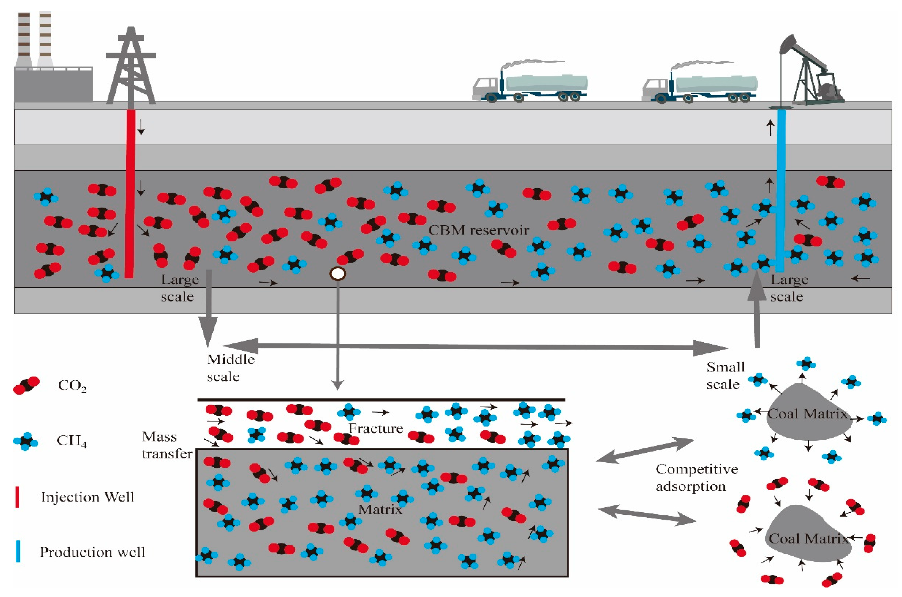
The CBM reservoir is saturated with mixture gas that contains only CH4 and CO2 (a water phase is not included in the model).
(3)
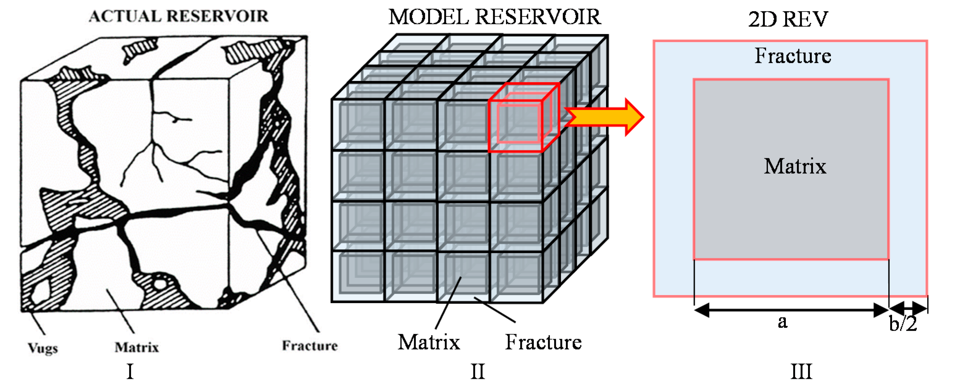
The CBM reservoir is considered as a dual-porosity media consisting of matrix and fractures. Each medium is homogeneous and isotropic.
(4)
The deformation of the CBM reservoir is infinitesimal.
(5)
The gas flow satisfies Darcy’s law in the matrix and the fracture system.

2.1. Dynamic Porosity and Permeability

In this section, we focus on modeling the porosity and permeability of the CBM reservoir by accurately considering the combined effect of the mechanical and adsorption/desorption during the process of CO2-ECBM recovery.

2.1.1. Dynamic Porosity and Permeability of Fractures

According to the effective stress principle for multi-porous media [36,37,38], the effective stress of the matrix and the fracture system of the CBM reservoir can be written as:
{ σ e m = σ ( α p m + β p f ) σ e f = σ β p f
where subscripts m and f represent the matrix and the fracture system, respectively; p is the gas pressure; σ is the average principal stress and can be expressed as Equation (2) [39]; α is the effective stress coefficient of the matrix; and β is the effective stress coefficient of the fracture system [40], and can be expressed as Equation (3):
σ = σ k k / 3 = ( σ 11 + σ 22 + σ 33 ) / 3
{ α = 1 K K m β = 1 K K f
In the above equation, Km and Kf are the bulk modulus of the coal matrix and the fracture system [41], K is the bulk modulus of the dual porosity media. The expression for K is defined as:
K = E 3 ( 1 2 v )
In that, v is the Poisson ratio of the dual porosity media, E is the elastic modulus of the dual porosity media.
Based on the Dalton’s law, the gas pressure (Pa) of a binary mixture of nonreactive gases in the coal matrix and the fracture system can be defined as [42,43]:
{ p m = p m 1 + p m 2 p f = p f 1 + p f 2
where subscript 1 represents CH4, and subscript 2 represents CO2.
The desorption induced shrinkage strain during gas production can be expressed as:
Δ ε s = ε s ε s 0
where [7,21,22,44]:
{ ε s = ε L i b i p m i 1 + b i p m i ε s 0 = ε L i b i p m i 0 1 + b i p m i 0
and εs is the strain induced by desorption with subscripted 0 representing the initial state; εL is the Langmuir-type strain coefficient, bi = 1/PLi and given by the extended Langmuir model [43].
The length of the REV is assumed as s, then,
s = a + b
After the initial equilibrium state, and based on the accurate consideration of the effective stress in the coal matrix and the fracture system, the volumetric strain of the REV can be expressed as:
Δ ε v = a 3 s 3 K 1 Δ σ e m s 3 a 3 s 3 K f Δ σ e f + a 3 s 3 Δ ε s
The first item on the right of the equal sign of the above equation means the degree of contribution of the coal matrix volumetric strain induced by the change in effective stress of the coal matrix to the volumetric strain of the REV. The second item means the degree of contribution of the fracture system volumetric induced by the change in effective stress in the fracture to the volumetric strain of the REV. The third item represents the degree of contribution of matrix shrinkage caused by gas desorption.
The following equation can be written based on Equations (1) and (9):
Δ ε v = a 3 s 3 K m [ Δ σ ( α Δ p m + β Δ p f ) ] s 3 a 3 s 3 K f ( Δ σ β Δ p f ) + a 3 s 3 Δ ε s
Therefore, we can rewrite the change of effective stress in the fracture by:
Δ σ β Δ p f = 1 a 3 s 3 K m + s 3 a 3 s 3 K f ( a 3 s 3 Δ ε s Δ ε v + 1 s 3 a 3 K m α Δ p m )
The fracture deformation can be obtained from the following equation as:
Δ b = b 0 3 K f ( Δ σ β Δ p f )
Then the change of fracture porosity can be got base on the definition of fracture porosity as:
ϕ f ϕ f 0 = 1 + Δ b b 0 = 1 1 3 K f 1 a 3 s 3 K m + s 3 a 3 s 3 K f ( a 3 s 3 Δ ε s Δ ε v + 1 s 3 a 3 K m α Δ p m )
Based on the Cubic Law [45], we can finally write the permeability ratio for fracture system of dual porosity media like coal as:
k f k f 0 = ( ϕ f ϕ f 0 ) 3 = [ 1 1 3 K f 1 a 3 s 3 K m + s 3 a 3 s 3 K f ( a 3 s 3 Δ ε s Δ ε v + 1 s 3 a 3 K m α Δ p m ) ] 3

2.1.2. Dynamic Porosity and Permeability of Matrix

Similar to Equation (11), the change of effective stress in the matrix can be written as:
Δ σ ( α Δ p m + β Δ p f ) = 1 a 3 s 3 K m + s 3 a 3 s 3 K f ( a 3 s 3 Δ ε s Δ ε v + 1 s 3 a 3 K m α Δ p m ) α Δ p m
After the initial equilibrium state, and considering the shrinkage induced by gas desorption, the volumetric strain of the matrix can be expressed as:
ε m v = Δ σ ( α Δ p m + β Δ p f ) K m + Δ ε s = 1 K m [ 1 a 3 s 3 K m + s 3 a 3 s 3 K f ( a 3 s 3 Δ ε s Δ ε v + 1 s 3 a 3 K m α Δ p m ) α Δ p m ] + Δ ε s
When the volume of the matrix changes, the volume of pore in the matrix will change accordingly. We assume that pores in the matrix have the same strain as the matrix due to gas desorption [46,47]. Based on this assumption the volumetric strain of the pores in the matrix can be derived from:
ε m p v = Δ σ ( α Δ p m + β Δ p f ) K m p + Δ ε s = 1 K m p [ 1 a 3 s 3 K m + s 3 a 3 s 3 K f ( a 3 s 3 Δ ε s Δ ε v + 1 s 3 a 3 K m α Δ p m ) α Δ p m ] + Δ ε s
where Kmp is the bulk modulus of the pores in the matrix and can be derived as [38]:
K m p = K m ϕ m α
As the porosity of matrix can be written as:
ϕ m = V m p V m
d ϕ m = d ( V m p V m ) = V m p V m ( d V m p V m p d V m V m )
Therefore,
d ϕ m = ϕ m ( d ε m p v d ε m v )
Combining Equations (16)–(21), the change of matrix porosity can be derived as:
ϕ m ϕ m 0 = 1 + ϕ m 0 α K m ϕ m 0 [ 1 a 3 s 3 K m + s 3 a 3 s 3 K f ( a 3 s 3 Δ ε s Δ ε v + 1 s 3 a 3 K m α Δ p m ) α Δ p m ]
Therefore, the permeability ratio for the matrix of dual porosity media like coal as:
k m k m 0 = ( ϕ m ϕ m 0 ) 3 = { 1 + ϕ m 0 α K m ϕ m 0 [ 1 a 3 s 3 K m + s 3 a 3 s 3 K f ( a 3 s 3 Δ ε s Δ ε v + 1 s 3 a 3 K m α Δ p m ) α Δ p m ] } 3
After establishing the dynamic porosity and permeability model, the field equations should be illustrated, which may include the deformation characteristics of the CBM reservoir and the government equations of binary gas transport. In the following, we will demonstrate those necessary field equations during the process of CO2-ECBM recovery.

2.2. Governing Equations

A group of field equations for coal deformation and gas transport are defined in this section. And these field equations are coupled through the porosity/permeability model established in the above section for the dual porosity media like the CBM reservoir.

2.2.1. Deformation Equation

The deformation of dual porosity media has been widely studied, and the Navier-type equation for the dual-porosity model can be expressed as [48,49,50]:
G u i , j j + G 1 2 v u k , k j + f i = α p m , i + β p f , i + K ε s , i
where G is the shear stiffness.

2.2.2. Binary Gas Transport

The mass balance equation of the each component of gas (CH4/CO2) can be expressed for a static medium, that incorporates the convective and dispersion modes of transport but involves the interchange between adsorbed gas and free gas as [10,21,42,43,51,52]:
m i t + · ( v g · ρ i ) + ( D i m i F ) = Q s i
where the gas content of a component gas i is mi which includes both the free-phase and adsorbed gas; vg is the vector of convective velocity; ρi is the gas density in the matrix or the fracture; Di is the diffusion coefficient; miF represents the gas content of the free state in the matrix or the fracture; Qsi is the gas source or sink.
The mass of each component of gas (CH4/CO2) present in a unit of the matrix and fracture system can be expressed as follows [43,52].
For the matrix,
m m i = ϕ m ρ m i f r e e - g a s + ρ c ρ a i V L i b i m i 1 + b i p m i a d s o r b e d - g a s = ϕ m p m i M i R T + ρ c p a i M i R T V L i b i m i 1 + b i p m i
where ρai is the density of gas at standard conditions, and ρc is the coal density.
For the fracture,
m f i = ϕ f ρ f i = ϕ f p f i M i R T
The vector of convective velocity vg can be expressed as follows (the effect of gas gravity is neglected) [9,42,43].
For the matrix,
v g m = k m μ m p m = k m μ m ( p m 1 + p m 2 )
For the fracture,
v g f = k f μ f p f = k f μ f ( p f 1 + p f 2 )
In the above two equations, μm and μf are the gas viscosity of a nonpolar binary gas mixture in the matrix and fracture, respectively. They can be written as [43]:
μ m = μ 1 1 + p m 2 p m 1 M 2 M 1 + μ 2 1 + p m 1 p m 2 M 1 M 2
μ f = μ 1 1 + p f 2 p f 1 M 2 M 1 + μ 2 1 + p f 1 p f 2 M 1 M 2
Combining Equations (26)–(29), binary gas transport in the matrix can be expressed as Equations (32) and (33).
For CH4,
[ ϕ m + ρ c p a 1 V L 1 b 1 ( 1 + b 2 p m 2 ) ( 1 + b i p m i ) 2 ] p m 1 t ρ c p a 1 V L 1 b 1 b 2 p m 1 ( 1 + b i p m i ) 2 p m 2 t + p m 1 ϕ m t + ( k m μ m p m 1 p m ) + ( D 1 ϕ m p m 1 ) = w ( p m 1 p f 1 )
where w = 8 [ 1 + ( 2 / a 2 ) ] k m / μ m is the transfer coefficient between the matrix and the fracture.
And for CO2,
[ ϕ m + ρ c p a 2 V L 2 b 2 ( 1 + b 1 p m 1 ) ( 1 + b i p m i ) 2 ] p m 2 t ρ c p a 2 V L 2 b 1 b 2 p m 2 ( 1 + b i p m i ) 2 p m 1 t + p m 2 ϕ m t + ( k m μ m p m 2 p m ) + ( D 2 ϕ m p m 2 ) = w ( p m 2 p f 2 )
Binary gas transport in fracture system can be expressed as Equations (34) and (35).
For CH4,
p f 1 ϕ f t + ϕ f p f 1 t + · ( k f μ f p f 1 p f ) + ( D 1 ϕ f p f 1 ) = w ( p m 1 p f 1 )
and for CO2,
p f 2 ϕ f t + ϕ f p f 2 t + · ( k f μ f p f 2 p f ) + ( D 2 ϕ f p f 2 ) = w ( p m 2 p f 2 )
After establishing the constitutive relationships for the binary gas transport and the deformation of the CBM reservoir, we will solve these field equations including the dynamic porosity and permeability using the FEM.

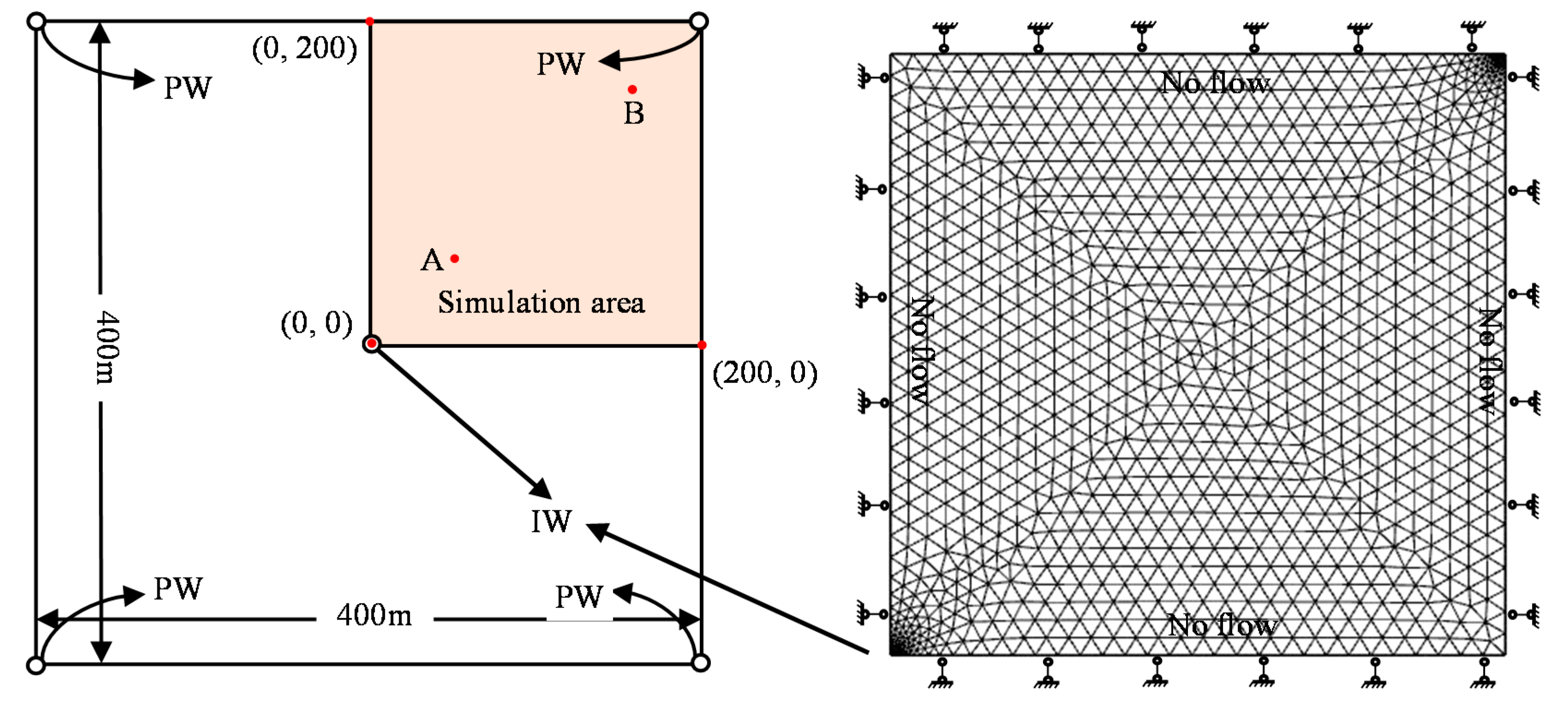
2.3. Model Implementation

The above mathematical model will be solved using the PDE module of COMSOL Multiphysics (a commercial FEM software). Next, we will describe the FEM model, which includes the solution domain, initial conditions, boundary conditions, and the main parameters in this simulation.
A production area of 400 m × 400 m defined to represent the CBM reservoir is shown in the left of Figure 3. The wells have a diameter of 0.1 m. It is a regular five-spot pattern with the IW in the center and the PW in the four corners of the square reservoir. Due to the symmetry of the configuration, only one-quarter (top right corner) of the production area is simulated as shown in the right of Figure 3. For the geomechanical boundary conditions of the simulation area, all four sides are confined in the normal direction (in COMSOL Multiphysics, the symmetric boundary condition is equivalent to a roller condition, and they both mean that the displacement is zero in the direction perpendicular (normal) to the boundary, but the boundary is free to move in the tangential direction) while the PW and IW are unconfined. For the binary gas flow, no flow conditions are applied to the boundaries except for the IW and PW. The initial gas pressure in the reservoir is 2.5 MPa. The initial pressures of CH4 and CO2 are set according to their composition. CH4 has an initial pressure of 2.3 MPa, and based on partial pressures, the initial pressure of CO2 is 0.2 MPa. A constant pressure of 0.1 MPa is applied to the PW and a constant pressure of 4MPa is applied to the IW. The fracture spacing and aperture are assumed as a = 0.01 m and b = 0.0002 m, respectively. The simulation time is 10,000 days. Meshing is as shown on the right in Figure 3. The remaining main parameters are listed in Table 1, which are mainly extracted from the literatures [51,53,54].

3. Results and Analysis

In this section, we will analyze the simulation results to reveal the evolution of reservoir permeability from different angles. We first analyze the permeability evolution of simulation area at different times. Then as shown in Figure 3, we select one group of locations that include two points on the diagonal line named as Point A (50, 50) and Point B (150, 150) to analyze how permeability evolves at these two points during the whole simulation period. After these analyses, another group of locations are selected closer to the wellheads and denoted as Point A′ (20, 20) and Point B′ (180, 180), respectively. Next we made a comparative analysis between those two groups. Finally, we adjust the IW pressure and analyze the influence of IW pressure on the evolution of reservoir permeability.

3.1. Permeability Evolution in the Whole Simulation Area

Here we analyze the matrix and fracture permeability separately from the reservoir scale. Matrix permeability and fracture permeability evolutions at the different times of 10th, 100th, 1000th, 2000th, 5000th, and 10,000th day are shown in Figure 4 and Figure 5, respectively. It can be seen that permeability evolution during the process of CO2-ECBM recovery is rather complicated.

3.1.1. Matrix Permeability Evolution

On the 10th day, the decrease in effective stress due to the increase in pore pressure caused by the injected gas will expand the pores and cause the increase of permeability near the IW. Conversely, the increase in effective stress due to the decrease in pore pressure caused by the produced gas will compress the pores and cause the decreased permeability near the PW.
On the 100th day, compared with the 10th day, the permeability in the vicinity of the IW decreased significantly, while the permeability in the vicinity of the PW has not significant changed. The reason for this phenomenon is because of gas adsorption/desorption in the matrix. To be specific, the coal matrix near the IW has begun to adsorb the injected CO2, which directly results in the expansion of the matrix and the decrease in pore volume and fracture aperture, eventually resulting in a decrease in permeability. Conversely, the coal matrix near the gas PW has begun to desorb CH4, which directly results in the shrinkage of the matrix and the increase of the pore volume and fracture aperture, eventually resulting in an increase in permeability. And, the increase in permeability induced by desorption offsets the decrease in permeability caused by the increase in effective stress, and ultimately results in no significant change in permeability near the gas PW.
When the time passes to the 1000th day, the range of decrease in permeability due to adsorption has greatly expanded to occupy the lower left corner of the entire model. While, for the upper right part of the simulation area, the increase in permeability caused by desorption is barely maintained and the permeability does not drop rapidly in this area. On the 2000th day, the permeability of the matrix in the upper right part of the simulation area is further reduced.
Approaching the 5000th day, it can be seen that the permeability in the upper right part of the simulation area is already lower than the lower left corner. This phenomenon will become more and more obvious with the increase of time.

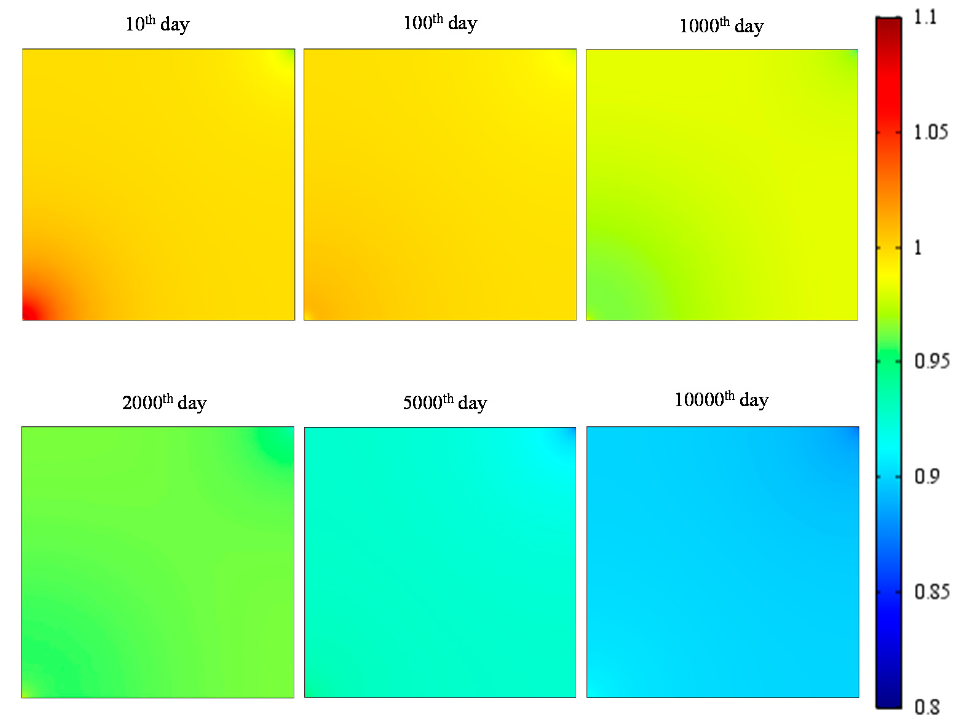
3.1.2. Fracture Permeability Evolution

The fracture permeability evolution is similar to that of the matrix. But the biggest difference between them is that the evolution of fracture permeability is more sensitive to the mechanical properties of the fracture.
On the 10th day, the decrease in effective stress due to the increase of gas pressure caused by the injected gas will expand the fracture aperture and eventually cause an increase in permeability near the IW. Conversely, the increase of effective stress due to the decrease of gas pressure caused by the produced gas will compress the fracture aperture and eventually cause a decrease in permeability near the PW.
As we have discussed before, as time goes by, the role of gas adsorption and desorption gradually becomes prominent and exceeds the effect of effective stress changes. Specifically, for gas adsorption near the IW, the decrease in fracture aperture and permeability exceed the increase in permeability caused by the reduction of effective stress; the final permeability shows a decreasing trend. However, the increase in fracture aperture and permeability induced by gas desorption near the gas PW cannot make up for the reduction in permeability caused by the increase of effective stress, and the final permeability also shows a trend of decreasing. This phenomenon becomes more and more profound on the 100th, 1000th, and 2000th days as shown in Figure 5. On the 5000th day, it can be seen that the permeability in the upper right part of the simulation area is already lower than that in the lower left corner.

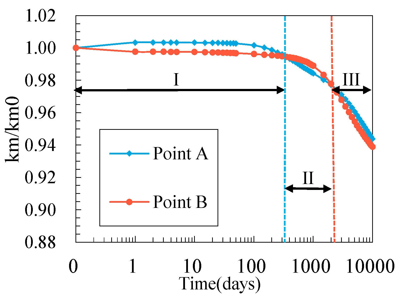
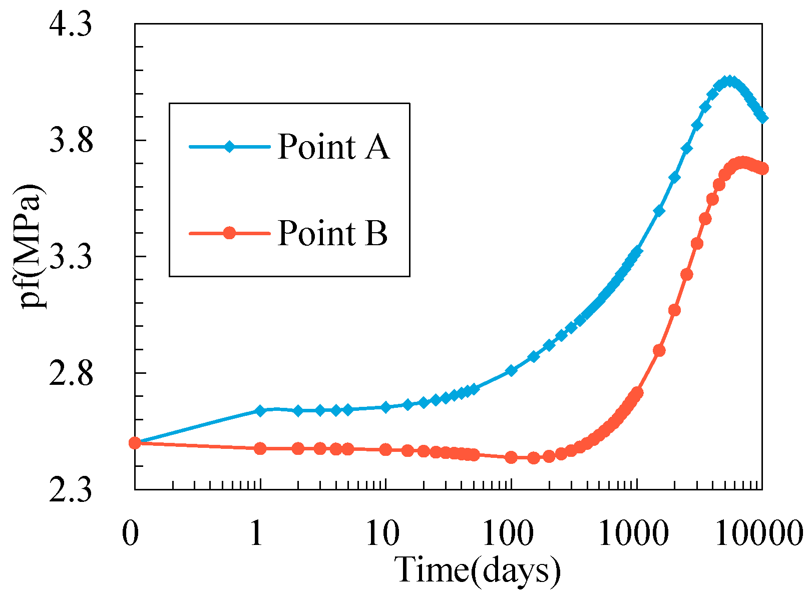
3.2. Permeability Evolutions at Different Locations

In this section, we focus on the evolutions of matrix permeability and fracture permeability at the two representative points named Point A and Point B. First of all, we understand the key parameters that affect the porosity/permeability evolutions during the process of CO2-ECBM recovery. As described in the previous section, the key factors that control the evolutions of porosity and permeability can be illustrated by Figure 6. Because the volumetric strain induced by the change of effective stress is difficult to show for coupled processes, next we will mainly analyze the evolution of pore pressure in the matrix, the pore pressure in fracture, the shrinkage/swelling induced by desorption/adsorption of gas in matrix, and the gas partial pressure in matrix.
The matrix permeability and fracture permeability evolutions as a function of time at the two different points in the simulation area are shown in Figure 7 and Figure 8, respectively. It can be seen intuitively that the trends of permeability changes in the matrix system are similar to that in the fracture system but their magnitudes are significantly different. The overall trend is a decline in permeability over time. Three stages (I, II, and III) can be divided based on the numerical values between Point A and Point B for both the matrix and the fracture system.

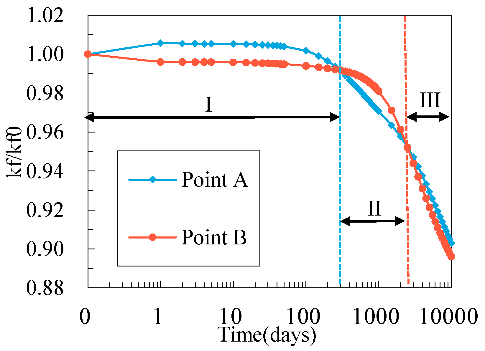
3.2.1. The First Stage (I)

At the first stage (I), the permeability at point A is larger than that of Point B: Point A is near the IW, while Point B is near the PW. As shown in Figure 9 and Figure 10, pore pressure will initially increase at Point A and decrease at Point B, which directly causes a decrease in effective stress at Point A and an increase in effective stress at Point B and in turn increases the pore volume and fracture aperture at Point A, while both are decreased at Point B. Therefore, in the first stage, the changes of pore pressure boost the permeability at point A and inhibit permeability at Point B.
However, this trend does not remain for a long time. For point A, the increased pore pressure breaks the previous equilibrium state of adsorption/desorption and the coal matrix begins to adsorb gas, as shown in Figure 11, which causes the swelling of the solid component of matrix. This process will decrease the pore size of the matrix and reduce the fracture aperture, which then can reduce the permeability. Please note at the same time, the increase in pore pressure can also increase permeability based on the effective stress principle. Therefore, a competitive relationship occurs at point A in the first stage. When the effect of the adsorption process exceeds that of the change in effective stress, the permeability of Point A decreases instead of increasing.
For Point B, the permeability behavior is opposite to that of Point A, specifically, the decreased pore pressure in the matrix promotes gas desorption. This process causes matrix shrinkage and increases the pore volumes and fracture aperture, which directly leads to permeability enhancement. However, the effect of the desorption process does not exceed the effect of the change in effective stress which can be seen from Figure 7 and Figure 8; there is no obvious rising stage of permeability at Point B, which can be explained from Figure 11 and Figure 12. In the first stage (I), the desorbed of gas at Point B does not cause a large shrinkage of the matrix because the main desorbed gas is CH4 which has a small Langmuir volume strain constant compared with CO2. These processes eventually result in a gradual crossover of the permeability ratio at point A and the permeability ratio at Point B, and then start the second stage (II).

3.2.2. The Second Stage (II)

At the second stage (II), the permeability at Point A is lower than permeability at Point B for both the matrix and fracture. But as shown from Figure 7 and Figure 8, the permeability difference between Point A and Point B is firstly increased and then decreased in the matrix and fracture in this stage. For the early period of this stage, the permeability evolution at Point A and Point B are the continuations of the end of the first stage. As Figure 12 shows, with the time goes, the injected gas transports to Point B, the partial pressure of CO2 increases dramatically while the partial pressure of CH4 decreases gently, which results in that the gas pressure tends to increase at Point B, as shown in Figure 9 and Figure 10. If the process of gas adsorption/desorption is not included in the analysis, the increased pore pressure would enhance permeability at Point B. However, as we can see from Figure 11, the swelling induced by adsorption at Point B gradually catches up with that of Point A. Furthermore, the total gas pressure at Point B is smaller than that at Point A. These two processes lead to a higher decline rate in permeability at Point B than that at Point A, which finally results in a gradual crossover of the permeability ratio line at Point A and the permeability ratio line at Point B, and then starts the third stage (III).

3.2.3. The Third Stage (III)

At the third stage (III), the general trend is that the permeability at Point A is slightly higher than that at Point B. This situation can be seen as a continuation of the second stage (II). To analyze its causes, we still need to start from the perspective of effective stress and adsorption/desorption of gas. On the one hand, the swelling induced by gas adsorption for Point A and Point B at this stage is very similar, as shown in Figure 11. One the other hand, the pore pressure in fracture and matrix at this stage at these two points always has a differential as shown in Figure 9 and Figure 10. This differential makes sure that the effective stress at Point A is lower than that of Point B. Hence, if we only consider the permeability change induced by the changes in effective stress, the permeability at Point A should be larger than that at Point B. If we combine the effects of effective stress and the effects of gas adsorption/desorption, the final result will not change significantly since the effects of gas adsorption/desorption at these two points are very similar. Therefore, the finally result is that the permeability at Point A is slightly higher than that at Point B.

3.3. Some Other Influencing Factors

3.3.1. Permeability Evolution Rules at Other Locations

Through comparing permeability evolution at Point A (50, 50) and Point B (150, 150), we find that the evolution of permeability in different locations in a reservoir is not always the same and is a function of the distance from the wells. In this section, a group of locations are selected closer to the wellheads and denoted as Point A′ (20, 20) and Point B′ (180, 180), respectively. We then made a comparative analysis between those four locations. The permeability evolutions at those points of the matrix and fracture are shown in Figure 13 and Figure 14, respectively. It is obvious that the matrix and fracture permeability evolution are similar but with different magnitudes.
Numerical results show that the farther the distance between two points in a group, the greater the gap in their permeabilities. This is because the farther the two points are located, the closer they are to the wells and the more dramatic the evolution of permeability. For the group closer to the wells, the permeability evolution starts and completes the stages of the entire process earlier.

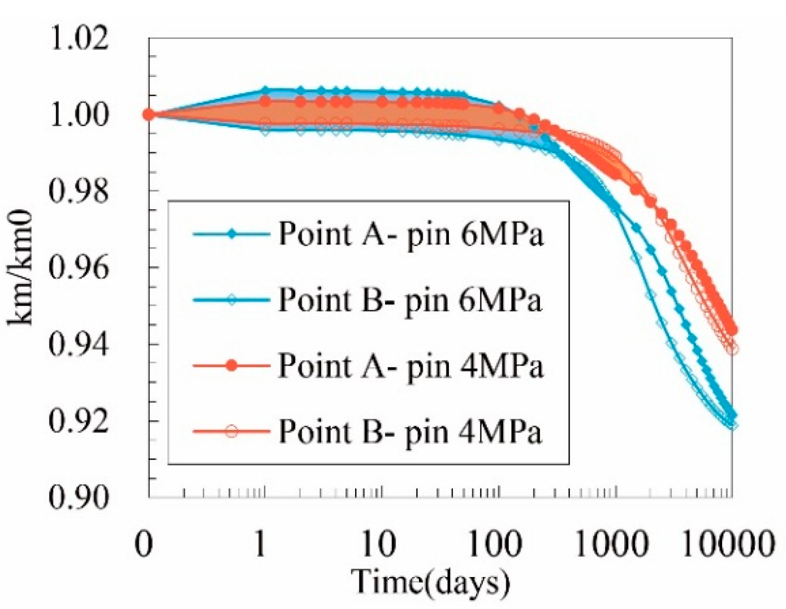
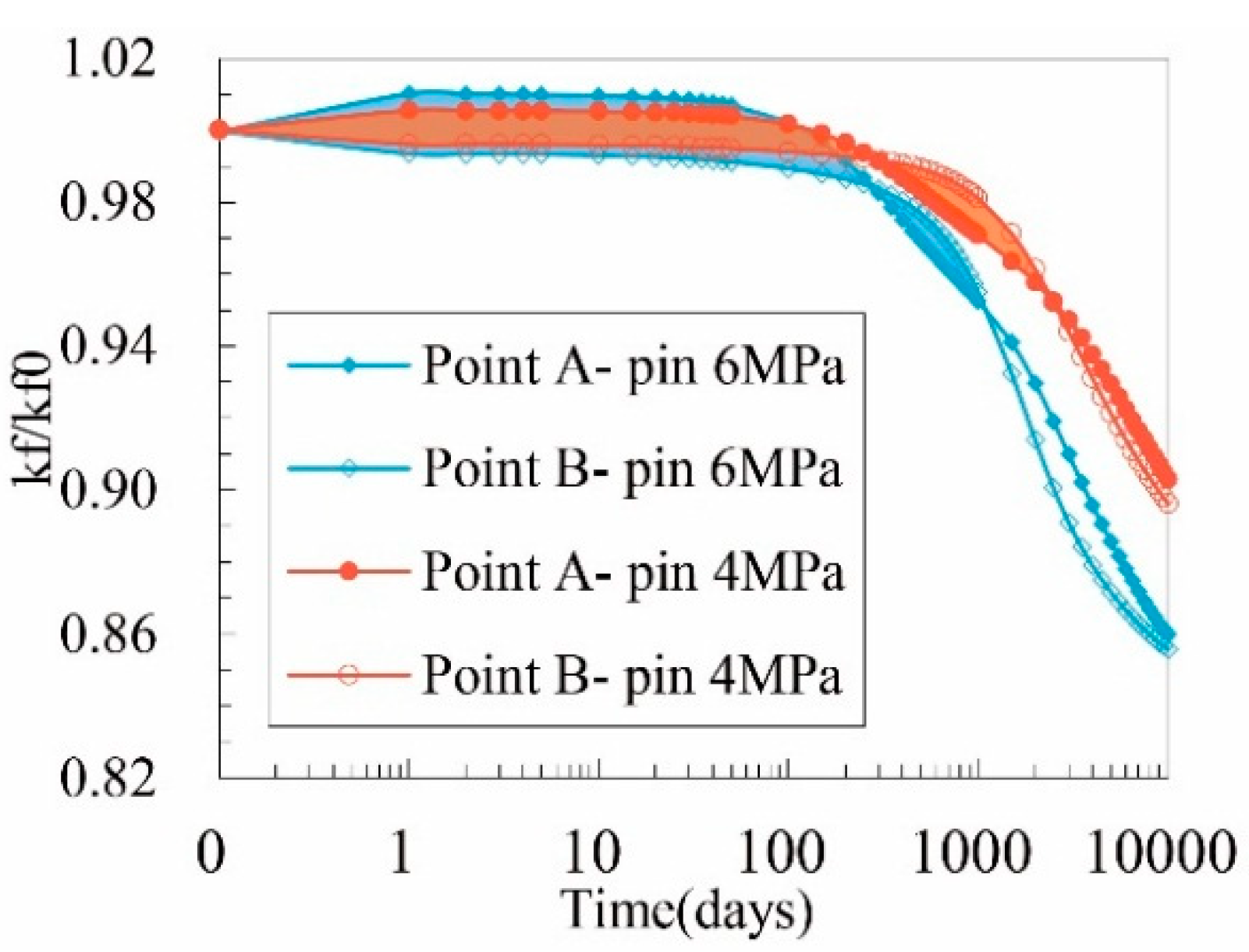
3.3.2. Permeability Evolution under Different Injection Pressures

As discussed before, the key factors that affect the permeability evolution are the changes in effective stress and the strain induced by gas adsorption or desorption. To change a factor that can influence not only the effective stress but also the gas adsorption/desorption, the most suitable parameter is pore pressure in the reservoir. As the flowing bottom hole pressure of the PW is already very small, we adjusted the injection pressure of CO2 to 6 MPa for the IW and compared it with the situations of 4 MPa injection pressure. The matrix permeability and fracture permeability evolutions at Point A and Point B under those two injection pressures are shown in Figure 15 and Figure 16, respectively.
Permeability evolution of matrix and fracture are also similar under the higher injection pressure condition. Higher injection pressure causes the permeability to evolve more dynamically. If we divide the whole process into three stages as before, we find that the group with higher injection pressure starts and completes those stages of the entire process earlier than the group with lower injection pressure.

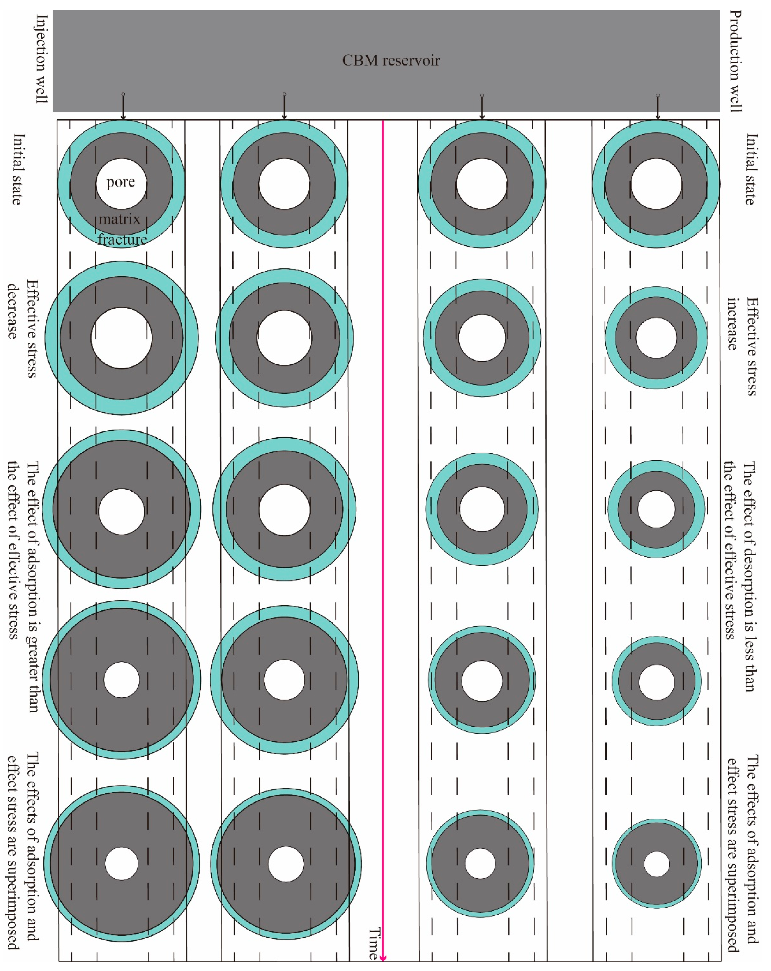
3.4. Schematic to Explain the Mechanisms

A schematic to summarize our previous analyses for the complex evolution of permeability during the process of CO2-ECBM recovery at different distances from the wells is shown in Figure 17. In the schematic, the innermost circle represents the matrix pore. The size of it represents the porosity/permeability of the matrix as the relationship between porosity and permeability described by the cubic law in this study. The thickness of the ring between the outermost circle and the second circle represents the fracture aperture and permeability. The size of the outermost circle is roughly the result of the combination of the strain caused by the change in the effective stress and the swelling/shrinkage caused by the adsorption/desorption. Finally, in the four locations shown in the figure, the left two points only represent their relative distance from the IW, and the right two points represent only their relative distance from the PW.

4. Conclusions

This study has built a dual porosity/permeability model through accurately expressing the volumetric strain of the matrix and fracture from a three-dimensional method which aims to reveal the reservoir permeability evolution during the process of CO2-ECBM recovery. This model has accommodated the key competing processes of mechanical deformation and adsorption/desorption-induced swelling/shrinkage of the CBM reservoir and it also considered the effect of fracture aperture and effective stress difference between fracture and matrix. We then numerically solved the permeability model using a group of multi-field coupling equations with FEM to understand how permeability evolves temporally and spatially in a CBM reservoir. From our multifaceted analyses of the results, the following conclusions can be drawn.
(1)
The evolution of reservoir permeability near the IW and the PW are very different. The reason for this is because the combined effect of effective stress changes and gas adsorption and desorption. Therefore, when analyzing the evolution of reservoir permeability during the process of CO2-ECBM recovery, it is not enough to only consider the evolution of the reservoir average permeability or the evolution of the permeability at a certain location in the reservoir.
(2)
Since the Langmuir volumetric strain constant of CO2 is greater than that of CH4, the swelling due to the adsorption of CO2 is greater than the shrinkage due to desorption of CH4. As a result, adsorption is the main factor for the change of permeability for regions near the IW, while the change in effective stress is the main cause for the change in permeability for regions the PW. Therefore, the overall trend of the evolution of permeability of the entire reservoir shows a downward trend.
(3)
Permeability evolution near the wells is the most dramatic. The farther away from the well, the gentler the evolution of permeability during the process of CO2-ECBM recovery. When we increase the injection pressure of CO2, the reservoir permeability evolution becomes quicker and more dynamic.

Author Contributions

All authors contributed to publishing this paper. G.W. and K.W. contributed to the formulation of the overarching research goals and the theoretical formula derivation of the model; Y.J. contributed to the controlling of project progress; and S.W. provided language and pictures supports.

Funding

This study was supported by the National Natural Science Foundation of China (Nos. 51479108 and 41672281), the Taishan Scholar Talent Team Support Plan for Advantaged & Unique Discipline Areas, and the Fundamental Research Funds of Shandong University (2017JC001).

Acknowledgments

The authors would like to thank the editor and anonymous referees very much for their insightful comments which significantly improved the manuscript.

Conflicts of Interest

The authors declare no conflict of interest.

Abbreviations

σAverage principal stress (Pa)
σeEffective stress (Pa)
pGas pressure (Pa)
α, βEffective stress coefficients
KBulk modulus (Pa)
GShear modulus (Pa)
EElastic modulus (Pa)
vPoisson’s ratio
εsSorption-induced strain
εvVolumetric strain
kPermeability (m2)
φPorosity
KpBulk modulus of pore (Pa)
εvpVolumetric strain of pore
Increment of a variable
VVolume (m3)
sLength of REV (m)
DDiffusion coefficient (m2/s)
mGas mass content (kg/m3)
wTransfer coefficient (s−1)
VLLangmuir volume (m3/kg)
εLLangmuir volumetric strain
PLLangmuir pressure (Pa)
ρcCoal density (kg/m3)
TReservoir temperature (K)
QsGas source or sink (kg/m3/s)
aFracture spacing (m)
bFracture aperture (m)
µGas viscosity (Pa·s)
RGas constant (J/(mol·K))
MGas molecular weight (kg/mol)
mMatrix
fFracture
0Initial value of the variable
1CH4
2CO2
FFree gas
aStandard state

References

  1. Liu, J.; Chen, Z.; Elsworth, D.; Qu, H.; Chen, D. Interactions of multiple processes during CBM extraction: A critical review. Int. J. Coal Geol. 2011, 87, 175–189. [Google Scholar] [CrossRef]
  2. Yu, H.; Zhou, G.; Fan, W.; Ye, J. Predicted CO2 enhanced coalbed methane recovery and CO2 sequestration in China. Int. J. Coal Geol. 2007, 71, 345–357. [Google Scholar] [CrossRef]
  3. Damen, K.; Faaij, A.; Bergen, F.V.; Gale, J.; Lysen, E. Identification of early opportunities for CO2 sequestration—Worldwide screening for CO2-EOR and CO2-ECBM projects. Energy 2005, 30, 1931–1952. [Google Scholar] [CrossRef]
  4. Aminu, M.D.; Nabavi, S.A.; Rochelle, C.A.; Manovic, V. A review of developments in carbon dioxide storage. Appl. Energy 2017, 208, 1389–1419. [Google Scholar] [CrossRef]
  5. Bickle, M.J. Geological carbon storage. Nat. Geosci. 2009, 2, 815–818. [Google Scholar] [CrossRef]
  6. Zhu, Q.; Zhou, Q.; Li, X. Numerical simulation of displacement characteristics of CO2 injected in pore-scale porous media. J. Rock Mech. Geotech. Eng. 2016, 8, 87–92. [Google Scholar] [CrossRef]
  7. Wu, Y.; Liu, J.; Elsworth, D.; Chen, Z.; Connell, L.; Pan, Z. Dual poroelastic response of a coal seam to CO2 injection. Int. J. Greenh. Gas Control 2010, 4, 668–678. [Google Scholar] [CrossRef]
  8. Van Bergen, F.; Gale, J.; Damen, K.J.; Wildenborg, A.F.B. Worldwide selection of early opportunities for CO2-enhanced oil recovery and CO2-enhanced coal bed methane production. Energy 2004, 29, 1611–1621. [Google Scholar] [CrossRef]
  9. Wang, L.; Wang, Z.; Li, K.; Chen, H. Comparison of enhanced coalbed methane recovery by pure N2 and CO2 injection: Experimental observations and numerical simulation. J. Nat. Gas Sci. Eng. 2015, 23, 363–372. [Google Scholar] [CrossRef]
  10. Chen, Z.; Liu, J.; Elsworth, D.; Connell, L.D.; Pan, Z. Impact of CO2 injection and differential deformation on CO2 injectivity under in-situ stress conditions. Int. J. Coal Geol. 2010, 81, 97–108. [Google Scholar] [CrossRef]
  11. Shi, J.Q.; Durucan, S. A model for changes in coalbed permeability during primary and enhanced methane recovery. SPE Reserv. Eval. Eng. 2005, 8, 291–299. [Google Scholar] [CrossRef]
  12. White, C.M.; Smith, D.H.; Jones, K.L.; Goodman, A.L.; Jikich, S.A.; LaCount, R.B.; Dubose, S.B.; Ozdemir, E.; Morsi, B.I.; Schroeder, K.T. Sequestration of carbon dioxide in coal with enhanced coalbed methane recovery—A review. Energy Fuels 2005, 19, 659–724. [Google Scholar] [CrossRef]
  13. Pan, Z.; Connell, L.D. Modelling permeability for coal reservoirs: A review of analytical models and testing data. Int. J. Coal Geol. 2012, 92, 1–44. [Google Scholar] [CrossRef]
  14. Wei, Z.; Zhang, D. Coupled fluid-flow and geomechanics for triple-porosity/dual-permeability modeling of coalbed methane recovery. Int. J. Rock Mech. Min. Sci. 2010, 47, 1242–1253. [Google Scholar] [CrossRef]
  15. Gu, F.; Chalaturnyk, R. Permeability and porosity models considering anisotropy and discontinuity of coalbeds and application in coupled simulation. J. Pet. Sci. Eng. 2010, 74, 113–131. [Google Scholar] [CrossRef]
  16. Harpalani, S.; Schraufnagel, R.A. Shrinkage of coal matrix with release of gas and its impact on permeability of coal. Fuel 1990, 69, 551–556. [Google Scholar] [CrossRef]
  17. Cui, X.; Bustin, R.M. Volumetric strain associated with methane desorption and its impact on coalbed gas production from deep coal seams. AAPG Bull. 2005, 89, 1181–1202. [Google Scholar] [CrossRef]
  18. Wang, S.; Elsworth, D.; Liu, J. A mechanistic model for permeability evolution in fractured sorbing media. J. Geophys. Res. Solid Earth 2012. [Google Scholar] [CrossRef]
  19. Zang, J.; Wang, K. Gas sorption-induced coal swelling kinetics and its effects on coal permeability evolution: Model development and analysis. Fuel 2017, 189, 164–177. [Google Scholar] [CrossRef]
  20. Liu, J.; Chen, Z.; Elsworth, D.; Miao, X.; Mao, X. Evolution of coal permeability from stress-controlled to displacement–controlled swelling conditions. Fuel 2011, 90, 2987–2997. [Google Scholar] [CrossRef]
  21. Kumar, H.; Elsworth, D.; Mathews, J.P.; Liu, J.; Pone, D. Effect of CO2 injection on heterogeneously permeable coalbed reservoirs. Fuel 2014, 135, 509–521. [Google Scholar] [CrossRef]
  22. Chen, Z.; Liu, J.; Elsworth, D.; Pan, Z.; Wang, S. Roles of coal heterogeneity on evolution of coal permeability under unconstrained boundary conditions. J. Nat. Gas Sci. Eng. 2013, 15, 38–52. [Google Scholar] [CrossRef]
  23. Seidle, J.P.; Jeansonne, M.W.; Erickson, D.J. Application of matchstick geometry to stress dependent permeability in coals. In Proceedings of the SPE Rocky Mountain Regional Meeting, Casper, WY, USA, 18–21 May 1992. [Google Scholar]
  24. Seidle, J.R.; Huitt, L.G. Experimental measurement of coal matrix shrinkage due to gas desorption and implications for cleat permeability increases. In Proceedings of the International Meeting on Petroleum Engineering, Beijing, China, 14–17 November 1995. [Google Scholar]
  25. Palmer, I.; Mansoori, J. How permeability depends on stress and pore pressure in coalbeds: A new model. SPE Reserv. Eval. Eng. 1998, 1, 539–544. [Google Scholar] [CrossRef]
  26. Robertson, E.P.; Christiansen, R.L. Modeling permeability in coal using sorption-induced strain data. In Proceedings of the 2005 SPE Annual Conference and Technical Exhibition, Dallas, TX, USA, 9–12 October 2015. [Google Scholar] [CrossRef]
  27. Connell, L.D.; Lu, M.; Pan, Z. An analytical coal permeability model for tri-axial strain and stress conditions. Int. J. Coal Geol. 2010, 84, 103–114. [Google Scholar] [CrossRef]
  28. Zhang, H.; Liu, J.; Elsworth, D. How sorption-induced matrix deformation affects gas flow in coal seams: A new FE model. Int. J. Rock Mech. Min. Sci. 2008, 45, 1226–1236. [Google Scholar] [CrossRef]
  29. Liu, H.H.; Rutqvist, J. A new coal-permeability model: Internal swelling stress and fracture–matrix interaction. Transp. Porous Media 2010, 82, 157–171. [Google Scholar] [CrossRef]
  30. Wu, Y.; Liu, J.; Elsworth, D.; Miao, X.; Mao, X. Development of anisotropic permeability during coalbed methane production. J. Nat. Gas Sci. Eng. 2010, 2, 197–210. [Google Scholar] [CrossRef]
  31. Robertson, E.P. Measurement and Modeling of Sorption-Induced Strain and Permeability Changes in Coal; Idaho National Laboratory: Idaho Falls, ID, USA, 2005.
  32. Wang, G.; Wang, K.; Wang, S.; Elsworth, D.; Jiang, Y. An improved permeability evolution model and its application in fractured sorbing media. J. Nat. Gas Sci. Eng. 2018, 56, 222–232. [Google Scholar] [CrossRef]
  33. Gray, I. Reservoir engineering in coal seams: Part 1—The Physical Process of Gas Storage and Movement in Coal Seams. SPE Reserv. Eng. 1987, 2, 28–34. [Google Scholar] [CrossRef]
  34. Warren, J.E.; Root, P.J. The behavior of naturally fractured reservoirs. Soc. Pet. Eng. J. 1963, 3, 245–255. [Google Scholar] [CrossRef]
  35. Langmuir, I. The adsorption of gases on plane surfaces of glass, mica and platinum. J. Chem. Phys. 2015, 40, 1361–1403. [Google Scholar] [CrossRef]
  36. Elsworth, D.; Bai, M. Flow-deformation response of dual-porosity media. J. Geotech. Eng. 1992, 118, 107–124. [Google Scholar] [CrossRef]
  37. Chen, M.; Chen, Z. Effective stress laws for multi-porosity media. Appl. Math. Mech. 1999, 20, 1207–1213. [Google Scholar]
  38. Detournay, E.; Cheng, H.D. 5-fundamentals of poroelasticity. Anal. Des. Methods 1993, 140, 113–171. [Google Scholar]
  39. Sang, G.; Elsworth, D.; Miao, X.; Mao, X.; Wang, J. Numerical study of a stress dependent triple porosity model for shale gas reservoirs accommodating gas diffusion in kerogen. J. Nat. Gas Sci. Eng. 2016, 32, 423–438. [Google Scholar] [CrossRef]
  40. Biot, M.A. General theory of three-dimensional consolidation. J. Appl. Phys. 1941, 12, 155–164. [Google Scholar] [CrossRef]
  41. Liu, T.; Lin, B.; Yang, W. Impact of matrix–fracture interactions on coal permeability: Model development and analysis. Fuel 2017, 207, 522–532. [Google Scholar] [CrossRef]
  42. Xia, T.; Zhou, F.; Liu, J.; Hu, S.; Liu, Y. A fully coupled coal deformation and compositional flow model for the control of the pre-mining coal seam gas extraction. Int. J. Rock Mech. Min. Sci. 2014, 72, 138–148. [Google Scholar] [CrossRef]
  43. Ren, T.; Wang, G.; Cheng, Y.; Qi, Q. Model development and simulation study of the feasibility of enhancing gas drainage efficiency through nitrogen injection. Fuel 2017, 194, 406–422. [Google Scholar] [CrossRef]
  44. Li, X.; Elsworth, D. Geomechanics of CO2 enhanced shale gas recovery. J. Nat. Gas Sci. Eng. 2015, 26, 1607–1619. [Google Scholar] [CrossRef]
  45. Chilingar, G.V. Relationship between porosity, permeability, and grain-size distribution of sands and sandstones. Dev. Sedimentol. 1964, 1, 71–75. [Google Scholar]
  46. Zimmerman, R.W. Coupling in poroelasticity and thermoelasticity. Int. J. Rock Mech. Min. Sci. 2000, 37, 79–87. [Google Scholar] [CrossRef]
  47. Zimmerman, R.W.; Somerton, W.H.; King, M.S. Compressibility of porous rocks. J. Geophys. Res. Solid Earth 2012, 91, 12765–12777. [Google Scholar] [CrossRef]
  48. Cui, G.; Liu, J.; Wei, M.; Feng, X.; Elsworth, D. Evolution of permeability during the process of shale gas extraction. J. Nat. Gas Sci. Eng. 2018, 49, 94–109. [Google Scholar] [CrossRef]
  49. Liu, J.; Chen, Z.; Elsworth, D.; Miao, X.; Mao, X. Linking gas-sorption induced changes in coal permeability to directional strains through a modulus reduction ratio. Int. J. Coal Geol. 2010, 83, 21–30. [Google Scholar] [CrossRef]
  50. Wang, J.G.; Kabir, A.; Liu, J.; Chen, Z. Effects of non-Darcy flow on the performance of coal seam gas wells. Int. J. Coal Geol. 2012, 93, 62–74. [Google Scholar] [CrossRef]
  51. Wu, Y.; Liu, J.; Chen, Z.; Elsworth, D.; Pone, D. A dual poroelastic model for CO2-enhanced coalbed methane recovery. Int. J. Coal Geol. 2011, 86, 177–189. [Google Scholar] [CrossRef]
  52. Yin, G.; Deng, B.; Li, M.; Zhang, D.; Wang, W.; Li, W.; Shang, D. Impact of injection pressure on CO2–enhanced coalbed methane recovery considering mass transfer between coal fracture and matrix. Fuel 2017, 196, 288–297. [Google Scholar] [CrossRef]
  53. Mazumder, S.; Wolf, K.H.A.; Hemert, P.V.; Busch, A. Laboratory experiments on environmental friendly means to improve coalbed methane production by carbon dioxide/flue gas injection. Transp. Porous Media 2008, 75, 63–92. [Google Scholar] [CrossRef]
  54. Wong, S.; Law, D.; Deng, X.; Robinson, J.; Kadatz, B.; Gunter, W.D.; Ye, J.; Feng, S.; Fan, Z. Enhanced coalbed methane and CO2 storage in anthracitic coals—Micro-pilot test at South Qinshui, Shanxi, China. Int. J. Greenh. Gas Control 2007, 1, 215–222. [Google Scholar] [CrossRef]
Figure 1. Schematic of CO2-enhanced coalbed methane (CO2-ECBM) recovery from different scales.
Energies 11 02996 g001
Figure 2. Illustration of the structure of coalbed methane (CBM) reservoir: (I) actual reservoir; (II) model reservoir; and (III) a 2-D sketch of the representative element volume (REV) from the model reservoir.
Energies 11 02996 g002
Figure 3. The situations of a CBM reservoir and the simulation model used in this study: (left) the production area which shows a regular five-spot pattern CBM reservoir with the IW in the center and the PW in the four corners of the square; and (right) the simulation area which shows boundary condition and meshing situation of one-quarter (top right corner) of the CBM reservoir.
Energies 11 02996 g003
Figure 4. Matrix permeability evolution maps (km/km0) at different time.
Energies 11 02996 g004
Figure 5. Fracture permeability evolution maps (kf/kf0) at different time.
Energies 11 02996 g005
Figure 6. Key factors that control the evolutions of porosity and permeability.
Energies 11 02996 g006
Figure 7. Evolution of matrix permeability at Point A and Point B. Point A is close to the injection well (IW) and Point B is close to the production well (PW).
Energies 11 02996 g007
Figure 8. Evolution of fracture permeability at Point A and Point B. Point A is close to the IW and Point B is close to the PW.
Energies 11 02996 g008
Figure 9. Evolution of the total pore pressure in matrix at Point A and Point B. Point A is close to the IW and Point B is close to the PW.
Energies 11 02996 g009
Figure 10. Evolution of the total pore pressure in fracture at Point A and Point B. Point A is close to the IW and Point B is close to the PW.
Energies 11 02996 g010
Figure 11. Evolution of the coal matrix strain induced by adsorption/desorption of gas at Point A and Point B. Point A is close to the IW and Point B is close to the PW.
Energies 11 02996 g011
Figure 12. Evolution of partial pressure of CH4 and CO2 in the matrix at point A and point B. Point A is close to the IW and Point B is close to the PW.
Energies 11 02996 g012
Figure 13. Evolution of matrix permeability at different points.
Energies 11 02996 g013
Figure 14. Evolution of fracture permeability at different points.
Energies 11 02996 g014
Figure 15. Evolution of matrix permeability at different points under the 4 MPa and 6 MPa injection pressure.
Energies 11 02996 g015
Figure 16. Evolution of fracture permeability at different points under the 4 MPa and 6 MPa injection pressure.
Energies 11 02996 g016
Figure 17. The schematic of porosity/permeability evolution at different locations in the CBM reservoir during the process of CO2-ECBM recovery.
Energies 11 02996 g017
Table 1. Main input parameters for the simulation model.
SymbolValueMeanUnit
εL10.0128Langmuir volume strain of CH4-
εL20.0237Langmuir volume strain of CO2-
VL10.0256Langmuir volume of CH4m3/kg
VL20.0477Langmuir volume of CO2m3/kg
PL12.07 × 106Langmuir pressure of CH4Pa
PL21.38 × 106Langmuir pressure of CO2Pa
μ11.15 × 10⁻⁵Gas viscosity of CH4Pa·s
μ21.60 × 10⁻⁵Gas viscosity of CO2Pa·s
D13.6 × 10−12Diffusion coefficient of CH4m2/s
D25.8 × 10−12Diffusion coefficient of CO2m2/s
φm00.04Intrinsic porosity of matrix-
km01.0 × 10−17Intrinsic permeability of matrixm2
φf00.003Intrinsic porosity of fracture-
kf01.0 × 10−15Intrinsic permeability of fracturem2
E4 × 109Young’s modulus of coalPa
Km12 × 109Bulk modulus of matrixPa
Kf1.5 × 108Bulk modulus of fracturePa
v0.32Poisson’s ratio-

