A Review of Underground Soil and Night Sky as Passive Heat Sink: Design Configurations and Models

Abstract
1. Introduction
2. Earth-Air-Heat-Exchangers (EAHE)
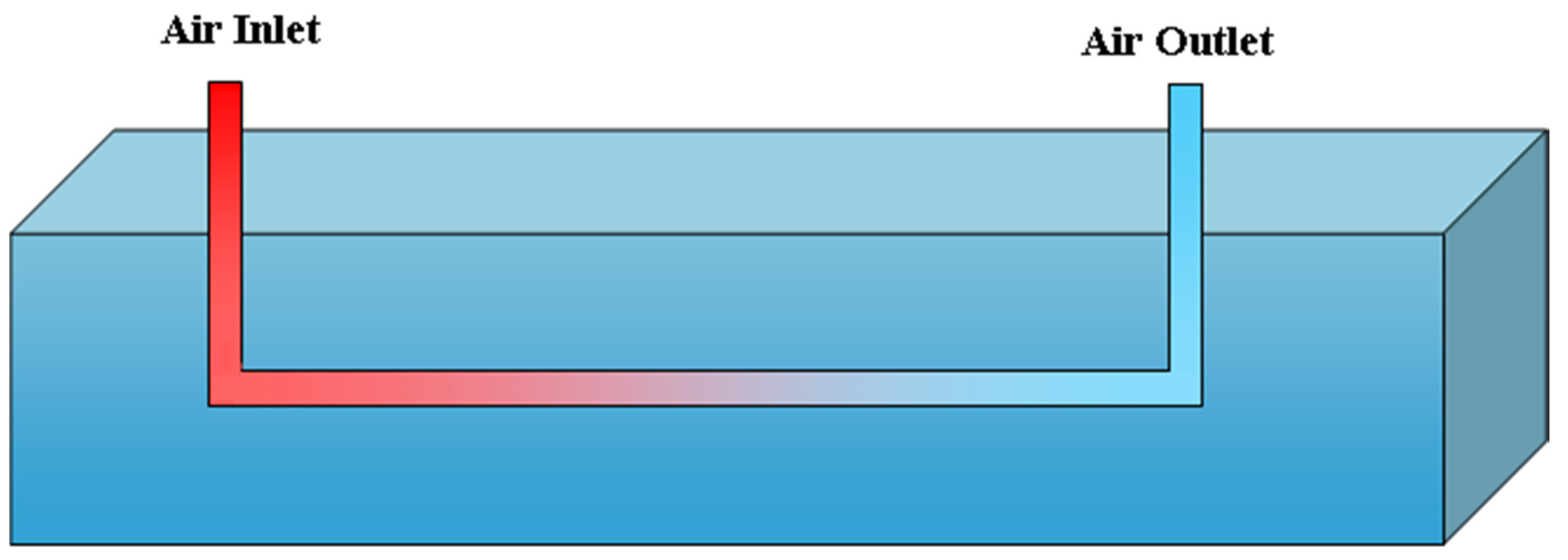
2.1. Principle
2.2. Applications
2.3. Configurations
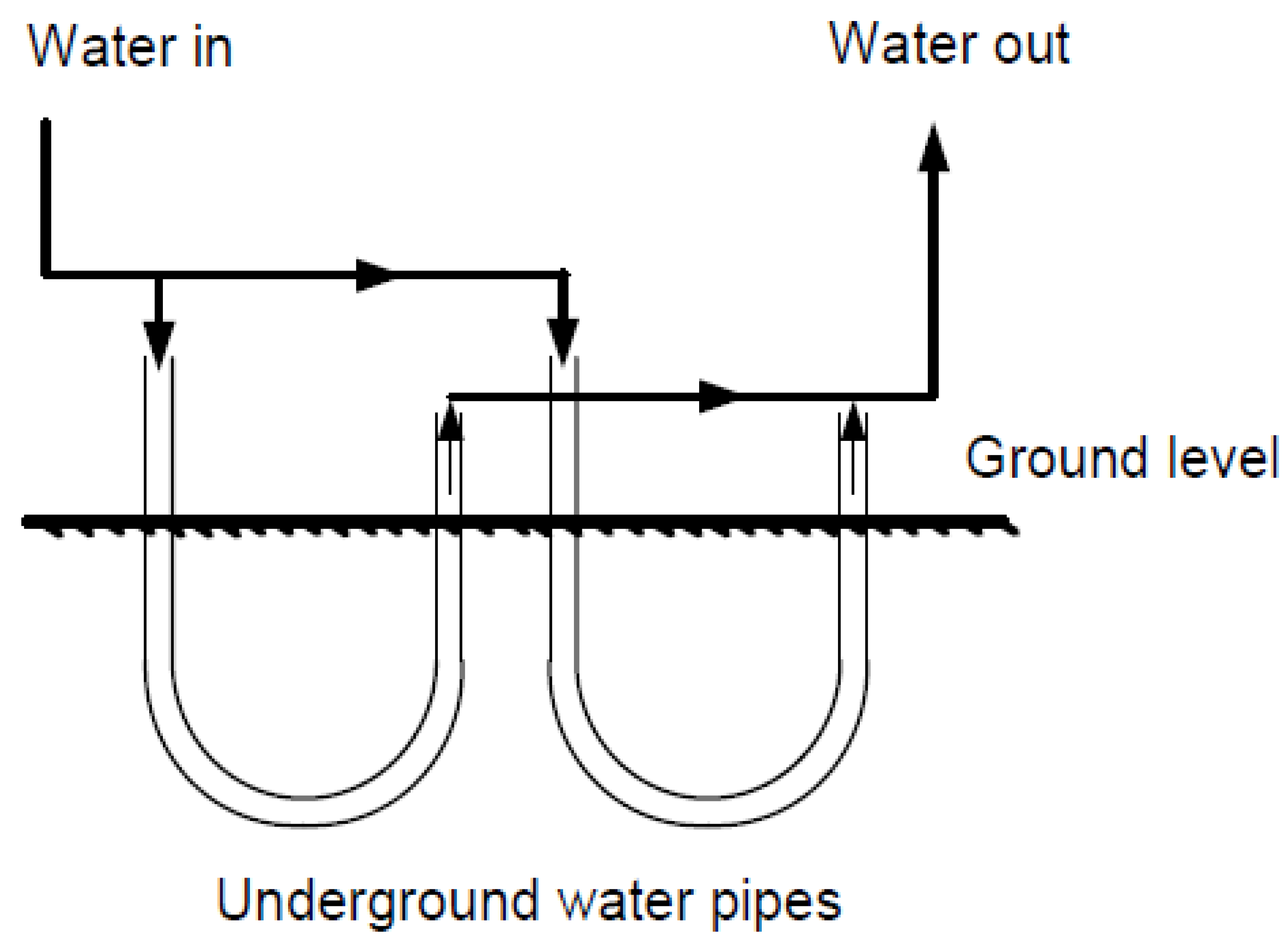
2.3.1. Single and Multiple Pipe Heat Exchanger
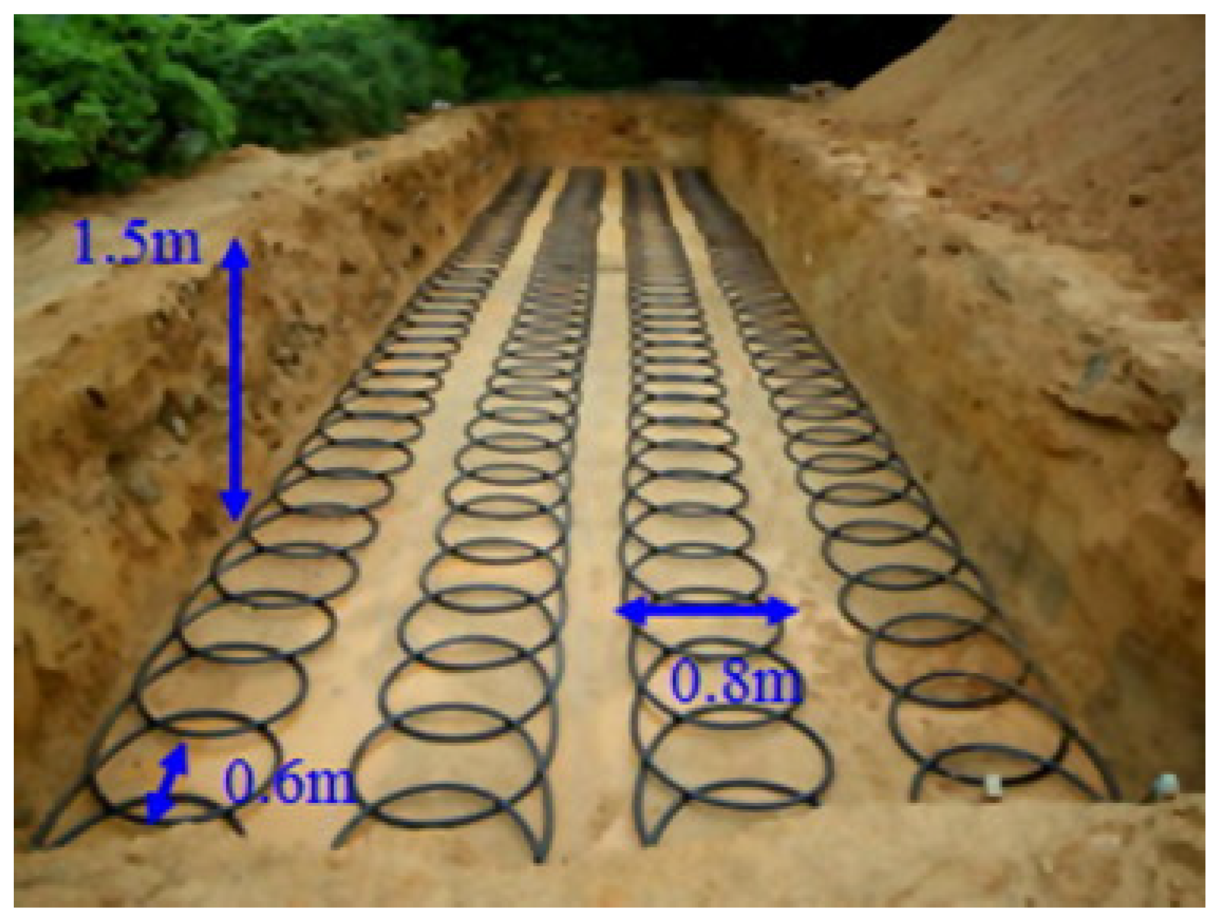
2.3.2. No Dig Heat Exchanger
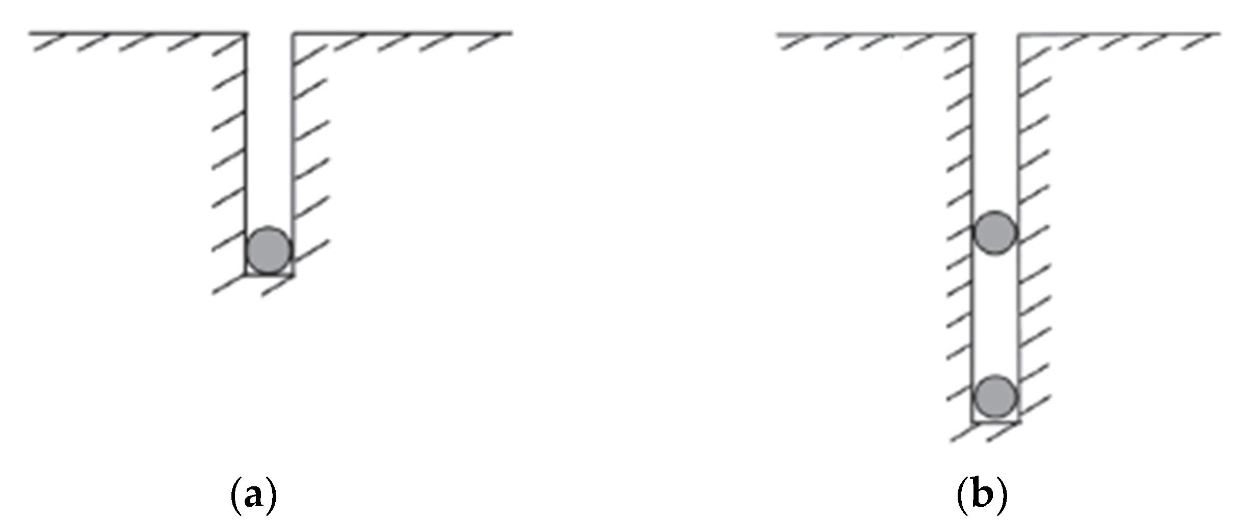
2.3.3. Ground Coupled Heat Pump (GCHP)
2.4. Influence of Different Parameters
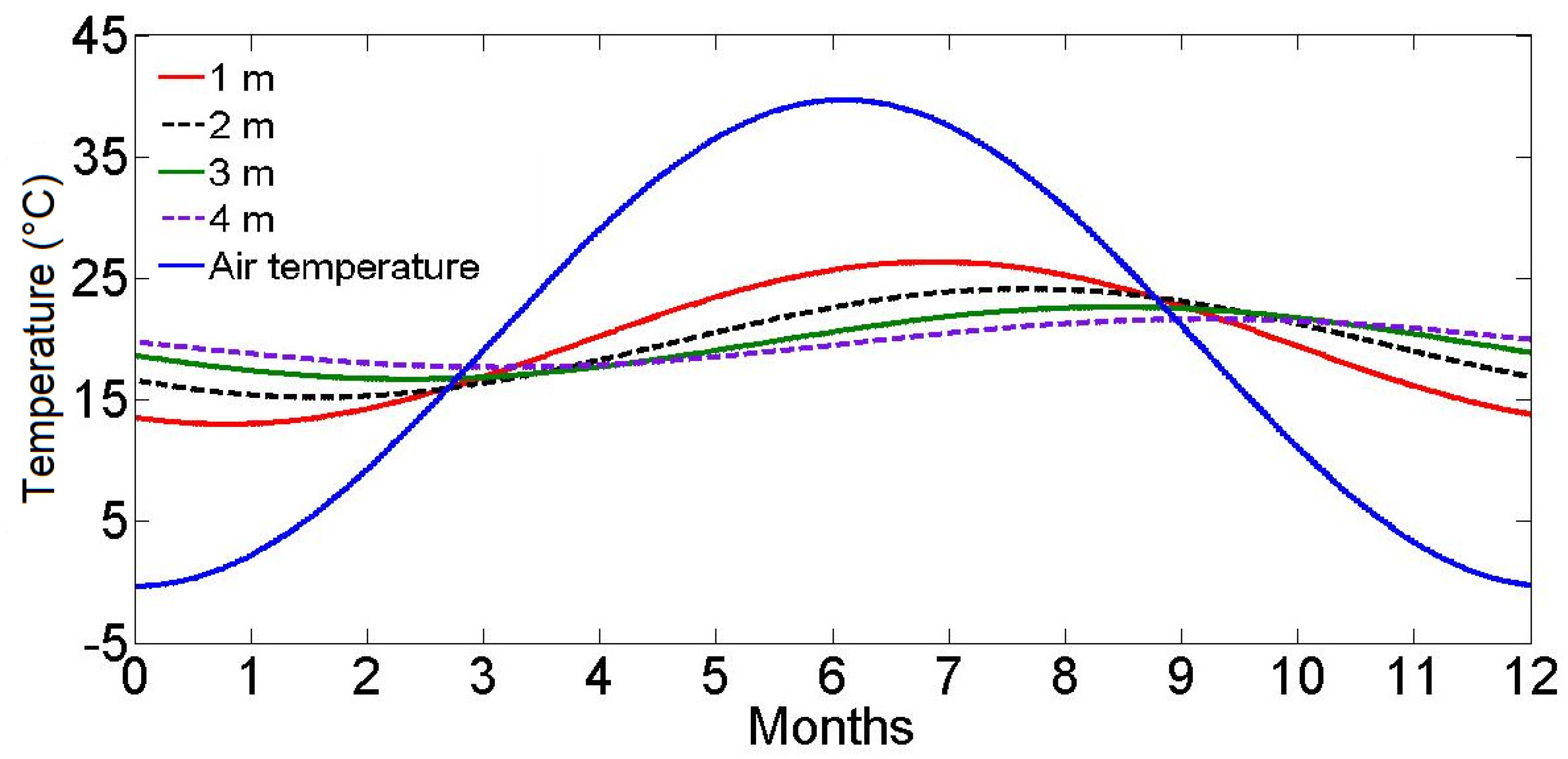
- Depth: As the time lag between the underground and ambient temperatures increases with depth at which the pipes are buried, the thermal performance of the EAHE system also improves by increasing depth. However, it was observed that the improvement in performance was negligible beyond the depths of 4 m [2,3,12,15,16,36,84].
- Length: Different lengths of buried pipes have been used in experimental projects and theoretical analyses [1,2,15,16,36,85,86,87,88]. Longer pipes typically resulted in better performance due to higher heat transfer with the soil. The heat transfer rate becomes very small as the temperature of fluid inside the pipes becomes close to the underground soil temperature. Any further pipe length then does not reduce the air temperature.
- Pipe radius: A number of researchers have performed parametric analysis to study the impact of pipe radius. Pipe radius has a direct impact on the convective heat transfer coefficient. Pipes with smaller radius experience higher heat transfer coefficients, which results in lower thermal resistance between the soil and air [2,15,16,86,89,90]. This would imply that using a smaller radius for the pipe should result in lower outlet temperature when the EAHE is operating in cooling mode, and higher outlet temperature when in heating mode. However, an interesting trend has been observed by some researchers in which the outlet temperature first decreases with increasing radius but then increases. The point at which this reversal begins is called the “critical radius” [84,86,88]. The reason behind such an interesting trend is the joint effect of low heat transfer coefficient and higher heat transfer area as the radius increases. In the analysis performed by Kumar et al. [86,88], they observed that the outlet temperature reduced in the cooling mode when the pipe radius was increased from 0.41 m to 0.52 m. This suggests that the increasing surface area of the underground pipe was the dominating factor over the reducing heat transfer coefficient. However, further increase in the radius of the underground pipe (0.58 and 0.70 m) caused the outlet temperature to increase, suggesting that the increase in heat transfer area was not large enough to overcome the impact of reducing heat transfer coefficient.
- Flow rate: Increase in flow velocity, and the mass flow rate causes higher outlet temperature when operating in cooling mode, and lower outlet temperature when operating in heating mode [2,6,15,36,44,45,55,85,86,88]. So, lower mass flow rate is typically considered a preferred situation, but may not result in the overall optimum performance. Bansal et al. investigated the impact of flow velocity (2.0, 3.2, 4.0 and 5.0 m/s) in both heating and cooling modes, and compared the results of the simulations with those from the experiments performed [9,10]. When the flow velocity increased from 2.0 m/s to 5.0 m/s, the total time spent by the air underground decreased by 2.5 times, which was the dominating factor compared to the 2.3 times increase in the heat transfer coefficient. They also observed that even though the reduction (or increase) in temperature was lower at higher flow velocities, the cooling (or heating) effect per unit time was higher. So, flow rate optimization is required depending on the application.
- Ground cover and soil type: Different ground covers, such as grass-covered soil, bare soil, high moisture soil, sand-covered soil etc., result in different thermal properties and underground temperatures [36,52,53,91,92]. Soil with high moisture content generally have better performance due to higher thermal conductivity, resulting in improved heat transfer with the underground pipes. Goswami et al. studied the variation of thermal conductivity with moisture content and time and showed its impact on the performance of the EAHE [45,46,47]. They observed that as the air passed through the pipes, and the surrounding soil was heated, the moisture from the pipe’s vicinity dissipated resulting in reduced thermal conductivity of the soil from the initial value of 1.1 W/m·K to less than 0.8 W/m·K. However, when the system was left idle off for 3 h, the moisture content in the soil was restored, and the thermal conductivity improved slightly to 0.9 W/m·K.
- Pipe material and thickness: Thermal conductivity of the pipe material can be an importance adder to the thermal resistance in the heat transfer process. Since the thickness of the buried pipe is generally very small (only a few millimeters), different materials do not result in very different thermal performances [9,10,36,90]. Bansal et al. compared the performance of two different materials (steel and PVC) for the underground pipes in both experimental and simulated conditions, and concluded that the overall performance and operation did not vary for the two materials [10]. The main reason for that was the larger contribution of the convective heat transfer coefficient compared to the conductive heat transfer coefficient on the overall heat transfer rate.
- Time: While analyzing the performance of an earth air heat exchanger, the earth is generally considered to be an infinite source or sink. The underground temperature is assumed to remain constant which is a valid assumption for systems that operate for a short duration. Even in cases where the underground temperature is impacted by the EAHE system, the change is very small. However, continued use of the EAHE system for a long time results in discharge (or extraction) of a large amount of heat to (or from) the earth. This may result in the permanent change of temperature in the area surrounding the buried pipes. Ileslamlou and Goswami examined an EAHE for 90 days, in which the system was operated for 16.5 h and then switched off for 7.5 h in a day [46,47]. During operation of the EAHE, the soil temperature increased, even though the increase was small. It then came down when the system was turned off. They observed that the resulting temperature after cool down was slightly higher than the starting temperature value. This trend continued for the entire time the EAHE was operated, resulting in a total increase at the outlet temperature by 2 °C [46,47].
- Air humidity: Relative humidity and moisture content of the air is another variable that needs to be considered in the design. If the air entering the pipes is at a high temperature and with high moisture content, condensation of water vapor could occur sooner along the pipe length [93]. Generally, if the air enters at a relative humidity of 30% or less, the probability of condensation is small. If condensation occurs at a large amount, it becomes important to pump out the condensate water at regular intervals to avoid corrosion and to ensure optimum performance.
2.5. Models
3. Night Sky Radiative Cooling
3.1. Principle
3.2. Configurations
3.2.1. Roof Pond
3.2.2. Flat Plate Radiators
3.3. Models
3.4. Effective Sky Temperature
4. Conclusions
- Ground coupled heat exchangers use the difference in temperature between ambient air and underground soil to cool the air in the summer and heat it in the winter
- Water can be used instead of air
- Earth air heat exchangers and ground coupled heat pumps have been used for air conditioning, and have been studied for use in condenser of a low temperature power generation system
- Choice depends on the location, season, application etc.
- Parameters that affect the performance of a ground coupled heat exchanger are depth, length of pipe, pipe radius, flow rate, ground cover and soil type, pipe material and thickness, and time
- Night sky radiative cooling allows for radiative heat transfer with the lowest temperature (~4 K) sink that is the sky
- Roof pond systems have been used to cool buildings
- Radiative heat transfer rate between the cooling body and the sky is heavily impacted by the ambient conditions such as wind speed, humidity, ambient temperature etc.
- Their combined effect is used to calculate the effective night sky temperature.
5. Declaration
Funding
Conflicts of Interest
Nomenclature
| T | Temperature |
| U | Overall heat transfer coefficient |
| H | Convective heat transfer coefficient |
| Cp | Specific heat |
| m | Mass flow rate |
| A | Differential area |
| δ | Penetration depth |
| r | Radial distance |
| W | Humidity |
| H | Enthalpy |
| D | Diameter |
| L | Length |
| R | Thermal resistance |
| k | Thermal conductivity |
| q’ | Heat transfer per unit area |
| IR | Infrared radiation |
| T | Time |
| V | Volumetric flow rate |
| Subscripts | |
| n | Element from inlet |
| s | Surface of the tube |
| e | Earth |
| f | Fluid |
| g | Gas |
| o | Outer wall |
| i | Inner wall |
| th | Thermal |
References
- Abbaspour-Fard, M.H.; Gholami, A.; Khojastehpour, M. Evaluation of an earth-to-air heat exchanger for the north-east of Iran with semi-arid climate. Int. J. Green Energy 2011, 8, 499–510. [Google Scholar] [CrossRef]
- Santamouris, M.; Mihalakakou, G.; Balaras, C.A.; Argiriou, A.; Asimakopoulos, D.; Vallindras, M. Use of buried pipes for energy conservation in cooling of agricultural greenhouses. Sol. Energy 1995, 55, 111–124. [Google Scholar] [CrossRef]
- Vidhi, R.; Goswami, D.Y.; Stefanakos, E.K. Parametric Study of Supercritical Rankine cycle and Earth-Air-Heat-Exchanger for Low Temperature Power Generation. Energy Procedia 2014, 49, 1228–1237. [Google Scholar] [CrossRef]
- Vidhi, R.; Goswami, D.Y.; Stefanakos, E.K. Supercritical Rankine cycle coupled with ground cooling for low temperature power generation. Energy Procedia 2014, 57, 524–532. [Google Scholar] [CrossRef]
- Yumrutaş, R.; Ünsal, M. Energy analysis and modeling of a solar assisted house heating system with a heat pump and an underground energy storage tank. Sol. Energy 2012, 86, 983–993. [Google Scholar] [CrossRef]
- Trombe, A.; Serres, L. Air-earth exchanger study in real site experimentation and simulation. Energy Build. 1994, 21, 155–162. [Google Scholar] [CrossRef]
- Said, S.A.M.; Habib, M.A.; Mokheimer, E.M.A.; El-Sharqawi, M.H. Feasibility of using ground-coupled condensers in A/C systems. Geothermics 2010, 39, 201–204. [Google Scholar] [CrossRef]
- Bansal, N.K.; Sodha, M.S. An earth-air tunnel system for cooling buildings. Tunn. Undergr. Space Technol. 1986, 1, 177–182. [Google Scholar] [CrossRef]
- Bansal, V.; Misra, R.; Agrawal, G.D.; Mathur, J. Performance analysis of earth-pipe-air heat exchanger for winter heating. Energy Build. 2009, 41, 1151–1154. [Google Scholar] [CrossRef]
- Bansal, V.; Misra, R.; Agrawal, G.D.; Mathur, J. Performance analysis of earth-pipe-air heat exchanger for summer cooling. Energy Build. 2010, 42, 645–648. [Google Scholar] [CrossRef]
- Ghosal, M.K.; Tiwari, G.N.; Srivastava, N.S.L. Thermal modeling of a greenhouse with an integrated earth to air heat exchanger: An experimental validation. Energy Build. 2004, 36, 219–227. [Google Scholar] [CrossRef]
- Sodha, M.S.; Sharma, A.K.; Singh, S.P.; Bansal, N.K.; Kumar, A. Evaluation of an earth-air tunnel system for cooling/heating of a hospital complex. Build. Environ. 1985, 20, 115–122. [Google Scholar] [CrossRef]
- Jacovides, C.P.; Mihalakakou, G. An underground pipe system as an energy source for cooling/heating purposes. Renew. Energy 1995, 6, 893–900. [Google Scholar] [CrossRef]
- Lee, K.H.; Strand, R.K. The cooling and heating potential of an earth tube system in buildings. Energy Build. 2008, 40, 486–494. [Google Scholar] [CrossRef]
- Mihalakakou, G.; Santamouris, M.; Asimakopoulos, D. On the cooling potential of earth to air heat exchangers. Energy Convers. Manag. 1994, 35, 395–402. [Google Scholar] [CrossRef]
- Mihalakakou, G.; Santamouris, M.; Asimakopoulos, D. Use of the ground for heat dissipation. Energy 1994, 19, 17–25. [Google Scholar] [CrossRef]
- Santamouris, M.; Mihalakakou, G.; Asimakopoulos, D.N. On the coupling of thermostatically controlled buildings with ground and night ventilation passive dissipation techniques. Sol. Energy 1997, 60, 191–197. [Google Scholar] [CrossRef]
- Sanaye, S.; Niroomand, B. Thermal-economic modeling and optimization of vertical ground-coupled heat pump. Energy Convers. Manag. 2009, 50, 1136–1147. [Google Scholar] [CrossRef]
- Sanaye, S.; Niroomand, B. Horizontal ground coupled heat pump: Thermal-economic modeling and optimization. Energy Convers. Manag. 2010, 51, 2600–2612. [Google Scholar] [CrossRef]
- Wang, H.; Qi, C. Performance study of underground thermal storage in a solar-ground coupled heat pump system for residential buildings. Energy Build. 2008, 40, 1278–1286. [Google Scholar] [CrossRef]
- Camdali, U.; Tuncel, E. An Economic Analysis of Horizontal Ground Source Heat Pumps (GSHPs) For Use in Heating and Cooling in Bolu, Turkey. Energy Sources Part B Econ. Plan. Policy 2013, 8, 290–303. [Google Scholar] [CrossRef]
- Ally, M.R.; Munk, J.D.; Baxter, V.D.; Gehl, A.C. Exergy analysis and operational efficiency of a horizontal ground-source heat pump system operated in a low-energy test house under simulated occupancy conditions. Int. J. Refrig. 2012, 35, 1092–1103. [Google Scholar] [CrossRef]
- Sanner, B.; Karytsas, C.; Mendrinos, D.; Rybach, L. Current status of ground source heat pumps and underground thermal energy storage in Europe. Geothermics 2003, 32, 579–588. [Google Scholar] [CrossRef]
- Mustafa Omer, A. Ground-source heat pumps systems and applications. Renew. Sustain. Energy Rev. 2008, 12, 344–371. [Google Scholar] [CrossRef]
- Florides, G.; Kalogirou, S. Ground heat exchangers—A review of systems, models and applications. Renew. Energy 2007, 32, 2461–2478. [Google Scholar] [CrossRef]
- Vidhi, R.; Garg, P.; Orosz, M.S.; Goswami, D.Y.; Pramod, K. Ground Cooling System for Improving the Efficiency of Low Temperature Power Generation. In Proceedings of the ASME 2014 8th International Conference on Energy Sustainability, Boston, MA, USA, 30 June–2 July 2014. [Google Scholar]
- Hamza, H.; Ali, A.; Taha, I.M.S.; Ismail, I.M. Cooling of water flowing through a night sky radiator. Sol. Energy 1995, 55, 235–253. [Google Scholar] [CrossRef]
- Mahdavinia, M.; Molla Ebrahim, A. The analysis of passive cooling strategies in Iranian traditional architecture: A case study in a hot and arid climate. Int. J. Environ. Sustain. 2013, 8, 47–59. [Google Scholar] [CrossRef]
- Vaz, J.; Sattler, M.A.; dos Santos, E.D.; Isoldi, L.A. Experimental and numerical analysis of an earth—Air heat exchanger. Energy Build. 2011, 43, 2476–2482. [Google Scholar] [CrossRef]
- Peretti, C.; Zarrella, A.; De Carli, M.; Zecchin, R. The design and environmental evaluation of earth-to-air heat exchangers (EAHE). A literature review. Renew. Sustain. Energy Rev. 2013, 28, 107–116. [Google Scholar] [CrossRef]
- Bisoniya, T.S.; Kumar, A.; Baredar, P. Experimental and analytical studies of earth-air heat exchanger (EAHE) systems in India: A review. Renew. Sustain. Energy Rev. 2013, 19, 238–246. [Google Scholar] [CrossRef]
- Li, H.; Yu, Y.; Niu, F.; Shafik, M.; Chen, B. Performance of a coupled cooling system with earth-to-air heat exchanger and solar chimney. Renew. Energy 2014, 62, 468–477. [Google Scholar] [CrossRef]
- Nayak, S.; Tiwari, G.N. Theoretical performance assessment of an integrated photovoltaic and earth air heat exchanger greenhouse using energy and exergy analysis methods. Energy Build. 2009, 41, 888–896. [Google Scholar] [CrossRef]
- Zeyghami, M.; Goswami, D.Y.; Stefanakos, E. A review of clear sky radiative cooling developments and applications in renewable power systems and passive building cooling. Sol. Energy Mater. Sol. Cells 2018, 178, 115–128. [Google Scholar] [CrossRef]
- Ozgener, O.; Ozgener, L. Exergoeconomic analysis of an underground air tunnel system for greenhouse cooling system. Int. J. Refrig. 2010, 33, 995–1005. [Google Scholar] [CrossRef]
- Ascione, F.; Bellia, L.; Minichiello, F. Earth-to-air heat exchangers for Italian climates. Renew. Energy 2011, 36, 2177–2188. [Google Scholar] [CrossRef]
- Thiers, S.; Peuportier, B. Thermal and environmental assessment of a passive building equipped with an earth-to-air heat exchanger in France. Sol. Energy 2008, 82, 820–831. [Google Scholar] [CrossRef]
- Ahmed, A.; Ip, K.; Miller, A.; Gidado, K. Thermal Performance of Earth-Air Heat Exchanger for Reducing Cooling Energy Demand of Office Buildings in the United Kingdom. In Proceedings of the 11th International Building Performance Simulation Association Conference, Glasgow, Scotland, 27–30 July 2009; pp. 2228–2235. [Google Scholar]
- Al-Ajmi, F.; Loveday, D.L.; Hanby, V.I. The cooling potential of earth-air heat exchangers for domestic buildings in a desert climate. Build. Environ. 2006, 41, 235–244. [Google Scholar] [CrossRef]
- Ramírez-Dávila, L.; Xamán, J.; Arce, J.; Álvarez, G.; Hernández-Pérez, I. Numerical study of earth-to-air heat exchanger for three different climates. Energy Build. 2014, 76, 238–248. [Google Scholar] [CrossRef]
- Vaz, J.; Sattler, M.A.; Brum, R.D.S.; dos Santos, E.D.; Isoldi, L.A. An experimental study on the use of Earth-Air Heat Exchangers (EAHE). Energy Build. 2014, 72, 122–131. [Google Scholar] [CrossRef]
- Liu, Q.; Du, Z.; Fan, Y. Heat and Mass Transfer Behavior Prediction and Thermal Performance Analysis of Earth-to-Air Heat Exchanger by Finite Volume Method. Energies 2018, 11, 1542. [Google Scholar] [CrossRef]
- Sinha, R.R.; Goswami, D.Y.; Klett, D.E. Theoretical and Experimental Analysis of Cooling Technique Using Underground Air Pipe; Solar World Forum: Brighton, UK, 1982; pp. 2105–2114. [Google Scholar]
- Dhaliwal, A.S.; Goswani, D.Y. Heat Transfer Analysis in Environmental Control Using an Underground Air Tunnel; ASME: Las Vegas, NV, USA, 1984; pp. 505–510. [Google Scholar]
- Goswami, D.Y.; Dhaliwal, A.S. Heat transfer analysis in environmental control using an underground air tunnel. J. Sol. Energy Eng. Trans. ASME 1985, 107, 141–145. [Google Scholar] [CrossRef]
- Goswami, D.Y.; Ileslamlou, S. Performance analysis of a closed-loop climate control system using underground air tunnel. J. Sol. Energy Eng. Trans. ASME. 1990, 112, 76–81. [Google Scholar] [CrossRef]
- Ileslamlou, S.; Goswami, D.Y. Performance Analysis of a Closed-Loop Climate Control System for Residential and Agricultural Buildings Using Underground Air Tunnel; Florida Energy Extension Service: Gainesville, FL, USA, 1987; pp. 873–877. [Google Scholar]
- Mihalakakou, G.; Santamouris, M.; Asimakopoulos, D. Modelling the earth temperature using multiyear measurements. Energy Build. 1992, 19, 1–9. [Google Scholar] [CrossRef]
- Mihalakakou, G.; Santamouris, M.; Asimakopoulos, D.; Papanikolaou, N. Impact of ground cover on the efficiencies of earth-to-air heat exchangers. Appl. Energy 1994, 48, 19–32. [Google Scholar] [CrossRef]
- Mihalakakou, G.; Santamouris, M.; Asimakopoulos, D. Modelling the thermal performance of earth-to-air heat exchangers. Sol. Energy 1994, 53, 301–305. [Google Scholar] [CrossRef]
- Mihalakakou, G.; Santamouris, M.; Asimakopoulos, D.; Tselepidaki, I. Parametric prediction of the buried pipes cooling potential for passive cooling applications. Sol. Energy 1995, 55, 163–173. [Google Scholar] [CrossRef]
- Mihalakakou, G.; Lewis, J.O.; Santamouris, M. The influence of different ground covers on the heating potential of earth-to-air heat exchangers. Renew. Energy 1996, 7, 33–46. [Google Scholar] [CrossRef]
- Mihalakakou, G.; Santamouris, M.; Lewis, J.O.; Asimakopoulos, D.N. On the application of the energy balance equation to predict ground temperature profiles. Sol. Energy 1997, 60, 181–190. [Google Scholar] [CrossRef]
- Santamouris, M.; Mihalakakou, G.; Argiriou, A.; Asimakopoulos, D.N. On the performance of buildings coupled with earth to air heat exchangers. Sol. Energy 1995, 54, 375–380. [Google Scholar] [CrossRef]
- Trombe, A.; Pettit, M.; Bourret, B. Air cooling by earth tube heat exchanger: Experimental approach. Renew. Energy 1991, 1, 699–707. [Google Scholar] [CrossRef]
- Eicker, U. Cooling strategies, summer comfort and energy performance of a rehabilitated passive standard office building. Appl. Energy 2010, 87, 2031–2039. [Google Scholar] [CrossRef]
- Eicker, U.; Huber, M.; Seeberger, P.; Vorschulze, C. Passive and low energy cooling of office buildings. Int. J. Vent. 2005, 4, 203–214. [Google Scholar] [CrossRef]
- Eicker, U.; Huber, M.; Seeberger, P.; Vorschulze, C. Limits and potentials of office building climatisation with ambient air. Energy Build. 2006, 38, 574–581. [Google Scholar] [CrossRef]
- Ghosal, M.K.; Tiwari, G.N. Modeling and parametric studies for thermal performance of an earth to air heat exchanger integrated with a greenhouse. Energy Convers. Manag. 2006, 47, 1779–1798. [Google Scholar] [CrossRef]
- Ghosal, M.K.; Tiwari, G.N. Parametric studies for heating performance of an earth to air heat exchanger coupled with a greenhouse. Int. J. Energy Res. 2005, 29, 991–1005. [Google Scholar] [CrossRef]
- Goswami, J. Dry Cooling in Solar Thermal Power Plants. ASME Conf. Proc. 2011, 2011, 663–670. [Google Scholar]
- Ozgener, L. A review on the experimental and analytical analysis of earth to air heat exchanger (EAHE) systems in Turkey. Renew. Sustain. Energy Rev. 2011, 15, 4483–4490. [Google Scholar] [CrossRef]
- Baglivo, C.; D’Agostino, D.; Congedo, P. Design of a Ventilation System Coupled with a Horizontal Air-Ground Heat Exchanger (HAGHE) for a Residential Building in a Warm Climate. Energies 2018, 11, 2122. [Google Scholar] [CrossRef]
- Hamada, Y.; Nakamura, M.; Saitoh, H.; Kubota, H.; Ochifuji, K. Improved underground heat exchanger by using no-dig method for space heating and cooling. Renew. Energy 2007, 32, 480–495. [Google Scholar] [CrossRef]
- Braud, H.J.; Klimkowski, H.; Baker, F.E. Earth-Coupled Heat Pump and Refrigeration Design and Applications; CONF-8606206; Louisiana State University: Baton Rouge, LA, USA, 1986. [Google Scholar]
- Yoshino, H.; Nagatomo, M.; Ishikawa, Y.; Kimura, S. Measurement of Thermal Performance of Earth Tube and Its Application to Heat Pump System. Sol. Eng. 1992, 1, 213–218. [Google Scholar]
- Ozgener, O.; Hepbasli, A.; Ozgener, L. A parametric study on the exergoeconomic assessment of a vertical ground-coupled (geothermal) heat pump system. Build. Environ. 2007, 42, 1503–1509. [Google Scholar] [CrossRef]
- Wu, H.; Wang, S.; Zhu, D. Modelling and evaluation of cooling capacity of earth-air-pipe systems. Energy Convers. Manag. 2007, 48, 1462–1471. [Google Scholar] [CrossRef]
- Sanaye, S.; Niroomand, B. Vertical ground coupled steam ejector heat pump; Thermal-economic modeling and optimization. Int. J. Refrig. 2011, 34, 1562–1576. [Google Scholar] [CrossRef]
- Econar Energy Systems. Geosource Heat Pump Handbook, 2nd ed.; Econar Energy Systems Corporation: Elk River, MN, USA, 1993. [Google Scholar]
- Eskilson, P. Thermal Analysis of Heat Extraction Boreholes; Lund University Press: Lund, Sweden, 1987. [Google Scholar]
- Ozgener, O.; Hepbasli, A. Performance analysis of a solar-assisted ground-source heat pump system for greenhouse heating: An experimental study. Build. Environ. 2005, 40, 1040–1050. [Google Scholar] [CrossRef]
- Kavanaugh, S. Optimization of Vertical Ground-Coupled Heat Pumps. Ph.D. Thesis, Oklahoma State University, Stillwater, OK, USA, 1984. [Google Scholar]
- Kavanaugh, S. Design and Performance of Vertical Ground Coupled Heat Pump Systems; ASHRAE Transactions: Atlanta, GA, USA, 1986; pp. 427–432. [Google Scholar]
- Kavanaugh, S. Design Method for Commercial Ground-Coupled Heat Pumps; ASHRAE Transactions: Atlanta, GA, USA, 1995; pp. 1088–1094. [Google Scholar]
- Kavanaugh, S. Water loop design for ground-coupled heat pumps. ASHRAE J. 1996, 38, 43–47. [Google Scholar]
- Kavanaugh, S. Ground source heat pumps. ASHRAE J. 1998, 40, 31–36. [Google Scholar]
- Soni, S.K.; Pandey, M.; Bartaria, V.N. Ground coupled heat exchangers: A review and applications. Renew. Sustain. Energy Rev. 2015, 47, 83–92. [Google Scholar] [CrossRef]
- Rivoire, M.; Casasso, A.; Piga, B.; Sethi, R. Assessment of Energetic, Economic and Environmental Performance of Ground-Coupled Heat Pumps. Energies 2018, 11, 1941. [Google Scholar] [CrossRef]
- Lu, Y.; Hooman, K.; Atrens, D.A.; Russell, H. An Experimental Facility to Validate Ground Source Heat Pump Optimisation Models for the Australian Climate. Energies 2017, 10, 138. [Google Scholar] [CrossRef]
- Fujii, H.; Yamasaki, S.; Maehara, T.; Ishikami, T.; Chou, N. Numerical simulation and sensitivity study of double-layer Slinky-coil horizontal ground heat exchangers. Geothermics 2013, 47, 61–68. [Google Scholar] [CrossRef]
- Chong, C.S.A.; Gan, G.; Verhoef, A.; Garcia, R.G.; Vidale, P.L. Simulation of thermal performance of horizontal slinky-loop heat exchangers for ground source heat pumps. Appl. Energy 2013, 104, 603–610. [Google Scholar] [CrossRef]
- Zarrella, A.; Capozza, A.; De Carli, M. Performance analysis of short helical borehole heat exchangers via integrated modelling of a borefield and a heat pump: A case study. Appl. Therm. Eng. 2013, 61, 36–47. [Google Scholar] [CrossRef]
- Kaushik, S.C.; Kumar, G.S. Performance evaluation of an earth air tunnel for space heating of a non air-conditioned building. Int. J. Ambient. Energy 1994, 15, 205–218. [Google Scholar] [CrossRef]
- Mihalakakou, G.; Lewis, J.O.; Santamouris, M. On the heating potential of buried pipes techniques—Application in Ireland. Energy Build. 1996, 24, 19–25. [Google Scholar] [CrossRef]
- Kumar, R.; Ramesh, S.; Kaushik, S.C. Performance evaluation and energy conservation potential of earth-air-tunnel system coupled with non-air-conditioned building. Build. Environ. 2003, 38, 807–813. [Google Scholar] [CrossRef]
- Kumar, R.; Kaushik, S.C.; Garg, S.N. Heating and cooling potential of an earth-to-air heat exchanger using artificial neural network. Renew. Energy 2006, 31, 1139–1155. [Google Scholar] [CrossRef]
- Kumar, R.; Kaushik, S.C.; Srikonda, A.R. Cooling and heating potential of earth-air tunnel heat exchanger (EATHE) for non-air-conditioned building. Int. J. Glob. Energy Issues 2003, 19, 373–386. [Google Scholar] [CrossRef]
- Puri, V.M. Heat and mass transfer analysis and modeling in unsaturated ground soils for buried tube systems. Energy Agric. 1987, 6, 179–193. [Google Scholar] [CrossRef]
- Badescu, V. Simple and accurate model for the ground heat exchanger of a passive house. Renew. Energy 2007, 32, 845–855. [Google Scholar] [CrossRef]
- Jacovides, C.P.; Mihalakakou, G.; Santamouris, M.; Lewis, J.O. On the ground temperature profile for passive cooling applications in buildings. Sol. Energy 1996, 57, 167–175. [Google Scholar] [CrossRef]
- Mihalakakou, G. On estimating soil surface temperature profiles. Energy Build. 2002, 34, 251–259. [Google Scholar] [CrossRef]
- Niu, F.; Yu, Y.; Yu, D.; Li, H. Heat and mass transfer performance analysis and cooling capacity prediction of earth to air heat exchanger. Appl. Energy 2015, 137, 211–221. [Google Scholar] [CrossRef]
- Zhang, J.; Haghighat, F. Development of Artificial Neural Network based heat convection algorithm for thermal simulation of large rectangular cross-sectional area Earth-to-Air Heat Exchangers. Energy Build. 2010, 42, 435–440. [Google Scholar] [CrossRef]
- Kumar, R.; Sinha, A.R.; Singh, B.K.; Modhukalya, U. A design optimization tool of earth-to-air heat exchanger using a genetic algorithm. Renew. Energy 2008, 33, 2282–2288. [Google Scholar] [CrossRef]
- Cucumo, M.; Cucumo, S.; Montoro, L.; Vulcano, A. A one-dimensional transient analytical model for earth-to-air heat exchangers, taking into account condensation phenomena and thermal perturbation from the upper free surface as well as around the buried pipes. Int. J. Heat Mass Transf. 2008, 51, 506–516. [Google Scholar] [CrossRef]
- Sharan, G.; Jadhav, R. Performance of Single Pass Earth-Tube Heat Exchanger: An Experimental Study. J. Agric. Eng. 2003, 40, 1–8. [Google Scholar]
- Tzaferis, A.; Liparakis, D.; Santamouris, M.; Argiriou, A. Analysis of the accuracy and sensitivity of eight models to predict the performance of earth-to-air heat exchangers. Energy Build. 1992, 18, 35–43. [Google Scholar] [CrossRef]
- Gauthier, C.; Lacroix, M.; Bernier, H. Numerical simulation of soil heat exchanger-storage systems for greenhouses. Sol. Energy 1997, 60, 333–346. [Google Scholar] [CrossRef]
- Liu, X.; Xiao, Y.; Inthavong, K.; Tu, J. A fast and simple numerical model for a deeply buried underground tunnel in heating and cooling applications. Appl. Therm. Eng. 2014, 62, 545–552. [Google Scholar] [CrossRef]
- Hollmuller, P.; Lachal, B. Cooling and preheating with buried pipe systems: Monitoring, simulation and economic aspects. Energy Build. 2001, 33, 509–518. [Google Scholar] [CrossRef]
- Hollmuller, P.; Lachal, B. Buried Pipe Systems with Sensible and Latent Heat Exchange: Validation of Numerical Simulation against Analytical Solution and Long-Term Monitoring. In Proceedings of the 9th International Building Performance Simulation Association, Montreal, Canada, 15–18 August 2005; pp. 411–418. [Google Scholar]
- Claesson, J.; Eskilson, P. Conductive heat extraction to a deep borehole: Thermal analyses and dimensioning rules. Energy 1988, 13, 509–527. [Google Scholar] [CrossRef]
- Eskilson, P.; Claesson, J. Simulation Model for Thermally Interacting Heat Extraction Boreholes. Numer. Heat Transf. 1988, 13, 149–165. [Google Scholar] [CrossRef]
- Bertagnolio, S.; Bernier, M.; Kummert, M. Comparing vertical ground heat exchanger models. J. Build. Perform. Simul. 2012, 5, 369–383. [Google Scholar] [CrossRef]
- Pasquier, P.; Marcotte, D.; Bernier, M.; Kummert, M. Simulation of Ground-Coupled Heat Pump Systems Using a Spectral Approach. In Proceedings of the 13th Conference of International Building Performance Simulation Association, Chambery, France, 26–28 August 2013; pp. 2691–2698. [Google Scholar]
- Zeng, H.; Diao, N.; Fang, Z. Heat transfer analysis of boreholes in vertical ground heat exchangers. Int. J. Heat Mass Transf. 2003, 46, 4467–4481. [Google Scholar] [CrossRef]
- Yang, H.; Cui, P.; Fang, Z. Vertical-borehole ground-coupled heat pumps: A review of models and systems. Appl. Energy 2010, 87, 16–27. [Google Scholar] [CrossRef]
- Bose, J.E.; Parker, J.D.; McQuiston, F.C.; American Society of Heating, R.; Engineers, A.-C. Design/Data Manual for Closed-Loop Ground-Coupled Heat Pump Systems; American Society of Heating, Refrigerating, and Air-Conditioning Engineers: New York, NY, USA, 1985. [Google Scholar]
- Hart, D.P.; Couvillion, R. Earth-Coupled Heat Transfer: Offers Engineers and Other Practitioners of Applied Physics the Information to Solve Heat Transfer Problems as They Apply to Earth-Coupling; National Water Well Association: Westerville, OH, USA, 1986. [Google Scholar]
- Lee, C.K.; Lam, H.N. Computer simulation of borehole ground heat exchangers for geothermal heat pump systems. Renew. Energy 2008, 33, 1286–1296. [Google Scholar] [CrossRef]
- Muraya, N.K. Numerical Modeling of the Transient Thermal Interference of Vertical U-Tube Heat Exchangers; Texas A&M University: College Station, TX, USA, 1994. [Google Scholar]
- Li, Z.; Zheng, M. Development of a numerical model for the simulation of vertical U-tube ground heat exchangers. Appl. Therm. Eng. 2009, 29, 920–924. [Google Scholar] [CrossRef]
- Li, Z.; Zhu, W.; Bai, T.; Zheng, M. Experimental study of a ground sink direct cooling system in cold areas. Energy Build. 2009, 41, 1233–1237. [Google Scholar] [CrossRef]
- Cimmino, M.; Bernier, M. A semi-analytical method to generate g-functions for geothermal bore fields. Int. J. Heat Mass Transf. 2014, 70, 641–650. [Google Scholar] [CrossRef]
- Trillat-Berdal, V.; Souyri, B.; Fraisse, G. Experimental study of a ground-coupled heat pump combined with thermal solar collectors. Energy Build. 2006, 38, 1477–1484. [Google Scholar] [CrossRef]
- Cui, P.; Yang, H.; Fang, Z. Numerical analysis and experimental validation of heat transfer in ground heat exchangers in alternative operation modes. Energy Build. 2008, 40, 1060–1066. [Google Scholar] [CrossRef]
- Ali, A.H.H. Passive cooling of water at night in uninsulated open tank in hot arid areas. Energy Convers. Manag. 2007, 48, 93–100. [Google Scholar] [CrossRef]
- Ali, A.H.H.; Saito, H.; Taha, I.M.S.; Kishinami, K.; Ismail, I.M. Effect of aging, thickness and color on both the radiative properties of polyethylene films and performance of the nocturnal cooling unit. Energy Convers. Manag. 1998, 39, 87–93. [Google Scholar] [CrossRef]
- Parker, D.S. Theoretical Evaluation of the Night Cool Nocturnal Radiation Cooling Concept; Submitted to U.S Department of Energy; No. FSEC Contract 20126003; Florida Solar Energy Center: Cocoa, FL, USA, 2005. [Google Scholar]
- Sabbagh, J.A.; Khalifa, A.M.A.; Olwi, I.A. Development of passive dry cooling system for power plants in arid land. Sol. Energy 1993, 51, 431–447. [Google Scholar] [CrossRef]
- Al-Nimr, M.A.; Kodah, Z.; Nassar, B. A theoretical and experimental investigation of a radiative cooling system. Sol. Energy 1998, 63, 367–373. [Google Scholar] [CrossRef]
- Erell, E.; Etzion, Y. Radiative cooling of buildings with flat-plate solar collectors. Build. Environ. 2000, 35, 297–305. [Google Scholar] [CrossRef]
- Khedari, J.; Waewsak, J.; Thepa, S.; Hirunlabh, J. Field investigation of night radiation cooling under tropical climate. Renew. Energy 2000, 20, 183–193. [Google Scholar] [CrossRef]
- Hay, H.R.; Yellott John, I. International Aspects of Air Conditioning with Movable Insulation. Sol. Energy 1969, 12, 427–438. [Google Scholar] [CrossRef]
- Yellott, J.I. Solar Energy heating and cooling of homes. Sol. Energy Eng. 1977, 12, 365–383. [Google Scholar]
- Yellott, J.I.; Manzo, J.P. Comfort cooling with solar energy. Specif Eng. 1978, 39, 94–99. [Google Scholar]
- Smith, G.B.; Granqvist, C.G.S. Green Nanotechnology: Solutions for Sustainability and Energy in the Built Environment; Taylor & Francis: Abingdon-on-Thames, UK, 2013. [Google Scholar]
- Olwi, I.A.; Sabbagh, J.A.; Khalifa, A.M.A. Mathematical modeling of passive dry cooling for power plants in arid land. Sol. Energy 1992, 48, 279–286. [Google Scholar] [CrossRef]
- Samuel, D.G.L.; Nagendra, S.M.S.; Maiya, M.P. Passive alternatives to mechanical air conditioning of building: Areview. Build. Environ. 2013, 66, 54–64. [Google Scholar] [CrossRef]
- Nwaigwe, K.N.; Okoronkwo, C.A.; Ogueke, N.V.; Anyanwu, E.E. Review of nocturnal cooling systems. Int. J. Energy A Clean Environ. 2010, 11, 117–143. [Google Scholar] [CrossRef]
- Dobson, R.T. Thermal modelling of a night sky radiation cooling system. J. Energy S. Afr. 2005, 16, 56–67. [Google Scholar]
- Meir, M.G.; Rekstad, J.B.; LØvvik, O.M. A study of a polymer-based radiative cooling system. Sol. Energy 2002, 73, 403–417. [Google Scholar] [CrossRef]
- Martin, M.; Berdahl, P. Characteristics of Infrared Sky Radiation in the United States. Sol. Energy 1984, 33, 321–336. [Google Scholar] [CrossRef]
- Molineaux, B.; Lachal, B.; Guisan, O. Thermal analysis of five outdoor swimming pools heated by unglazed solar collectors. Sol. Energy 1994, 53, 21–26. [Google Scholar] [CrossRef]
- Erell, E.; Etzion, Y. Analysis and experimental verification of an improved cooling radiator. Renew. Energy 1999, 16, 700–703. [Google Scholar] [CrossRef]
- Etzion, Y.; Erell, E. Low-cost long-wave radiators for passive cooling of buildings. Arch. Sci. Rev. 1999, 42, 79–86. [Google Scholar] [CrossRef]
- Martin, M.; Berdahl, P. The radiative cooling resource. In Proceedings of the Passive and Hybrid Solar Energy Update, Washington, DC, USA, 24–28 September 1983; MCC Associates Inc.: Silver Spring, MD, USA, 1983; pp. 39–46. [Google Scholar]
- Martin, M.; Berdahl, P. Summary of Results from the Spectral and Angular Sky Radiation Measurement Program. Sol. Energy 1984, 33, 241–252. [Google Scholar] [CrossRef]
- Tang, R.; Etzion, Y. Cooling performance of roof ponds with gunny bags floating on water surface as compared with a movable insulation. Renew. Energy 2005, 30, 1373–1385. [Google Scholar] [CrossRef]
- Tang, R.; Etzion, Y. On thermal performance of an improved roof pond for cooling buildings. Build. Environ. 2004, 39, 201–209. [Google Scholar] [CrossRef]
- Tang, R.; Etzion, Y.; Meir, I.A. Estimates of clear night sky emissivity in the Negev Highlands, Israel. Energy Convers. Manag. 2004, 45, 1831–1843. [Google Scholar] [CrossRef]
- Runsheng, T.; Etzion, Y.; Erell, E. Experimental studies on a novel roof pond configuration for the cooling of buildings. Renew. Energy 2003, 28, 1513–1522. [Google Scholar] [CrossRef]
- Sodha, M.S.; Singh, U.; Srivastava, A.; Tiwari, G.N. Experimental validation of thermal model of open roof pond. Build. Environ. 1981, 16, 93–98. [Google Scholar] [CrossRef]
- Sodha, M.S.; Singh, S.P.; Kumar, A. Thermal performance of a cool-pool system for passive cooling of a non-conditioned building. Build. Environ. 1985, 20, 233–240. [Google Scholar] [CrossRef]
- Clus, O.; Muselli, M.; Beysens, D.; Nikolayev, V.; Ouazzani, J. Computational Fluid Dynamic (CFD) Applied to Radiative Cooled Dew Condensers. In Proceedings of the First International Symposium on Environment Identities and Mediterranean Area, Corte-Ajaccio, France, 10–13 July 2006; pp. 217–221. [Google Scholar]
- Jain, D. Modeling of solar passive techniques for roof cooling in arid regions. Build. Environ. 2006, 41, 277–287. [Google Scholar] [CrossRef]
- Watmuff, J.; Charters, W.W.S.; Proctor, D. Solar and Wind Induced External Coefficient for Solar Collectors; Comples: New York, NY, USA, 1999. [Google Scholar]
- Jordan, R.C. Design Factors Influencing Solar Collectors, Low Temperature Engineering Application of Solar Energy. American Society of Heating, Refrigerating and Airconditioning Engineers: New York, NY, USA, 1967. [Google Scholar]
- Duffie, J.A.; Beckman, W.A. Solar Engineering of Thermal Process; Wiley: New York, NY, USA, 1991. [Google Scholar]
- Rincón, J.; Almao, N.; González, E. Experimental and numerical evaluation of a solar passive cooling system under hot and humid climatic conditions. Sol. Energy 2001, 71, 71–80. [Google Scholar] [CrossRef]
- Ito, S.; Miura, N. Studies of radiative cooling systems for storing thermal energy. J. Sol. Energy Eng. Trans. ASME 1989, 111, 251–256. [Google Scholar] [CrossRef]
- Ito, S.; Miura, N.; Takahashi, T. Studies of a Sky Radiative Thermosyphon Cooling System for Storing Thermal Energy. In Nippon Kikai Gakkai Ronbunshu, B Hen/Transactions of the Japan Society of Mechanical Engineers, Part B; The Japan Society of Mechanical Engineers: Tokyo, Japan, 1987; Volume 53, pp. 1102–1107. [Google Scholar]
- Spanaki, A.; Kolokotsa, D.; Tsoutsos, T.; Zacharopoulos, I. Theoretical and experimental analysis of a novel low emissivity water pond in summer. Sol. Energy 2012, 86, 3331–3344. [Google Scholar] [CrossRef]
- Mills, A.F. Heat Transfer; Prentice Hall: Upper Saddle River, NJ, USA, 2001. [Google Scholar]
- Erell, E.; Etzion, Y. Heating experiments with a radiative cooling system. Build. Environ. 1996, 31, 509–517. [Google Scholar] [CrossRef]
- Berdahl, P.; Martin, M. Emissivity of Clear Skies. Sol. Energy 1984, 32, 663–664. [Google Scholar] [CrossRef]
- Berdahl, P.; Fromberg, R. The Thermal Radiance of Clear Skies. Sol. Energy 1982, 29, 299–314. [Google Scholar] [CrossRef]
- Centeno, V.M. New formulae for the equivalent night sky emissivity. Sol. Energy 1982, 28, 489–498. [Google Scholar] [CrossRef]
- Berger, X.; Buriot, D.; Garnier, F. About the equivalent radiative temperature for clear skies. Sol. Energy 1984, 32, 725–733. [Google Scholar] [CrossRef]
- Chen, B.; Kasher, J.; Maloney, J.; Girgis, G.; Clark, D. Determination of the clear sky emissivity for use in cool storage roof and roof pond applications. In Proceedings of the American Solar Energy Society, Denver, CO, USA, 19–23 August 1991. [Google Scholar]
- Chen, B.; Clark, D.; Maloney, J.; Mei, W.; Kasher, J. Measurement of night sky emissivity in determining radiant cooling from cool storage roofs and roof ponds. In Proceedings of the National Passive Solar Conference, Minneapolis, MN, USA, 15–20 July 1995; Volume 20, pp. 310–313. [Google Scholar]
- National Renewable Energy Lab, Solar Radiation Research Laboratory. Daily plots and raw data files. Available online: http://www.nrel.gov/midc/srrl_bms/ (accessed on 24 April 2014).
- Vidhi, R. Organic Fluids and Passive Cooling in a Supercritical Rankine Cycle for Power Generation from Low Grade Heat Sources. Available online: https://scholarcommons.usf.edu/etd/5322 (accessed on 15 August 2018).


| Reference | Model Details | Location |
|---|---|---|
| Cucumo [96] | 1-Dimensional heat transfer in soil for sinusoidal variation in air temperature. | Ahmedabad, India [97], Greensboro, NC [45], Athens, Greece [98] |
| Goswami et al. [44,45,46,47] | 2-D iterative solution. Pipe was divided in many sections, and output from one was considered as input to the next. | Greensboro, NC, Gainesville, FL |
| Mihalakakou [51] | Parametric model for overall heat transfer coefficient, U using radius, pipe length, depth and velocity. The coefficients of the polynomial were determined from empirical relations. | Athens, Greece |
| Trombe [6] | 1-D heat transfer analysis on pipe sections. | Toulouse, France |
| Gauthier [99] | 3-D numerical model. The entire region was divided into several control volumes, and finite difference analysis was used for solving heat transfer equation on each. | Quebec, Canada |
| Kumar [87] | 2-D model using Neural Networks. | Mathura, India |
| Kumar [95] | 2-D model using Genetic Algorithms. | Mathura, India |
| Vaz [41] | Numerical solution based on finite volume analysis using ANSYS FLUENT. | Viamao-RS, Brazil |
| Liu [100] | 3-D numerical model using cylindrical coordinates. Pipe length was divided into several elemental discs. | Chongqing, China |
| Hollmuller [101,102] | 2-D numerical model. Pipe was divided into many sections, and energy balance was performed on each section iteratively. | Switzerland |
| Reference | Model Description | Location |
|---|---|---|
| Zeng [107] | Thermal resistances between soil and fluid (R11), and the resistance between two pipes (R12 and R13) were calculated separately. | N/A |
| Bose [109] | 1-D model for thermal resistance. | N/A |
| Hart [110] | Underground soil is treated as an infinite sink and borehole as an infinite line source which has a heat rate of q1 per unit length. | N/A |
| Sanaye [18,69] | Thermal resistance between the soil and the pipe is calculated. | Tuscaloosa, Alabama |
| Lee [111] | 3-D solution using finite difference analysis in rectangular coordinates. | N/A |
| Muraya [112] | Heat transfer analysis was done using transient finite-element method. | N/A |
| Li [113] | 3-D finite volume model was developed with a triangular mesh. | Harbin, China [114] |
| Bernier [106] | Average fluid temperature was calculated using g-function and thermal resistances [115]. | Le Bourget-du-Lac, France [116] |
| Cui [117] | Numerical solutions using finite element method. | Hong Kong |
| Ref. | System Description | Model Details and Underlying Assumptions | Experiment Location |
|---|---|---|---|
| Meir [133] | Inclined radiator panel connected with a water reservoir | Lumped model using [134,135] | Oslo, Norway |
| Erell & Etzion [123,136,137] | Flat plate radiator to cool a building | Lumped model with a linearized form of Stefan-Boltzmann law proposed by [138] | Sede-Boqer, Israel |
| Ali [27] | Open loop system with a hot water tank feeding into two parallel plate radiators | Lumped model applied on a number of sections along the radiator. Sky radiation calculations were obtained from [139] | Assiut, Egypt |
| Tang & Etzion [140,141] | Roof pond that included gunny bags floating on top of the water surface | Roof pond had thermally stratification along the depth. Sky radiations were calculated with [142] Stratification: | Seder Boker, Israel (Results are shown in [143]) |
| Tang & Etzion [140] | Roof pond with movable insulating layer | Roof pond is assumed to be perfectly stratified during the day and fully mixed at night. | Seder Boker, Israel (Results are shown in [143]) |
| Sodha et al. [144,145] | Open roof pond | Lumped model with constant radiative and convective heat transfer coefficients. | New Delhi, India |
| Clus et al. [146] | Funnel shaped radiative condenser | CFD analysis. | Corsica Island, France |
| Jain [147] | Roof pond with movable insulation | Fourier expansion was used on lumped model of energy balance equation. Different heat transfer coefficients were determined using [148,149,150]. | Rajasthan, India |
| Rincon et al. [151] | Roof pond with movable insulation | Numerical solution with finite volume method. Hourly data measured for outdoor temperature and solar irradiance was used. | Maracaibo, Venezuela |
| Ali [118] | Thermally uninsulated open tank | Heat transfer analysis was performed on each wall of the tank using the lumped model. Sky radiation was calculated using [150]. | Assiut, Egypt |
| Ito & Miura [152,153] | Radiator panels connected with water storage tank | Lumped model using radiative heat transfer calculation based on [150]. | Atsugi, Japan |
| Spanaki et al. [154] | Roof pond covered with a protective floating cloth | Analysis of the thermally stratified water tank was done using the model proposed by Tang et al. [140,141]. | Heraklion city, Greece |
| Dobson [132] | Radiator panel connected with a storage tank | Steady state lumped model for both storage tank and radiator. Sky emissivity was calculated using [155]. | Seder Boker, Israel [156] |
| Ref. | Model | Location |
|---|---|---|
| Tang [142] | Negev Highlands, Israel | |
| Berdahl and Fromberg [158] | during night during day | Arizona, Maryland, Missouri |
| Berdahl and Martin [157] | Arizona, Texas, Maryland, Missouri, Florida, Nevada | |
| Centeno [159] | Venezuela | |
| Berger [160] | Carpentras, France | |
| Chen [161,162] | during night during day | Nebraska and Texas |
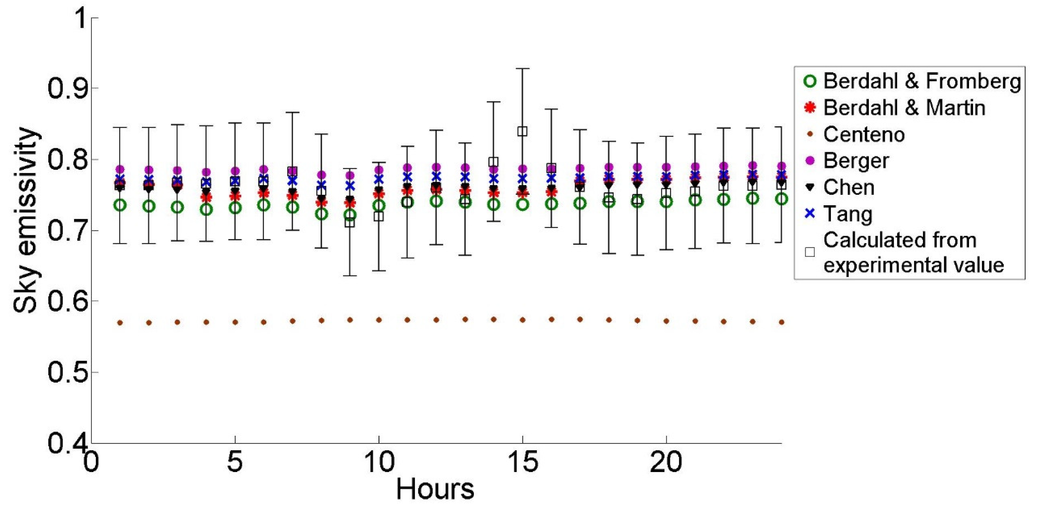
| S. No. | Model | Root Mean Square Error in Emissivity Value |
|---|---|---|
| 1. | Berdahl & Fromberg | 0.0350 |
| 2. | Berdahl & Martin | 0.0272 |
| 3. | Centeno | 0.1907 |
| 4. | Berger | 0.0348 |
| 5. | Chen | 0.0246 |
| 6. | Tang | 0.0270 |
© 2018 by the author. Licensee MDPI, Basel, Switzerland. This article is an open access article distributed under the terms and conditions of the Creative Commons Attribution (CC BY) license (http://creativecommons.org/licenses/by/4.0/).
Share and Cite
Vidhi, R. A Review of Underground Soil and Night Sky as Passive Heat Sink: Design Configurations and Models. Energies 2018, 11, 2941. https://doi.org/10.3390/en11112941
Vidhi R. A Review of Underground Soil and Night Sky as Passive Heat Sink: Design Configurations and Models. Energies. 2018; 11(11):2941. https://doi.org/10.3390/en11112941
Chicago/Turabian StyleVidhi, Rachana. 2018. "A Review of Underground Soil and Night Sky as Passive Heat Sink: Design Configurations and Models" Energies 11, no. 11: 2941. https://doi.org/10.3390/en11112941
APA StyleVidhi, R. (2018). A Review of Underground Soil and Night Sky as Passive Heat Sink: Design Configurations and Models. Energies, 11(11), 2941. https://doi.org/10.3390/en11112941