Article

Multi-Dimensional Sparse-Coded Ambient Backscatter Communication for Massive IoT Networks

School of Information and Communication Engineering, Sungkyunkwan University, Suwon 440-746, Korea
*
Author to whom correspondence should be addressed.
Energies 2018, 11(10), 2855; https://doi.org/10.3390/en11102855
Submission received: 23 September 2018 / Revised: 13 October 2018 / Accepted: 19 October 2018 / Published: 22 October 2018

Abstract

:
In this paper, we propose a multi-dimensional sparse-coded ambient backscatter communication (MSC-AmBC) system for long-range and high-rate massive Internet of things (IoT) networks. We utilize the characteristics of the ambient sources employing orthogonal frequency division multiplexing (OFDM) modulation to mitigate strong direct-link interference and improve signal detection of AmBC at the reader. Also, utilization of the sparsity originated from the duty-cycling operation of batteryless RF tags is proposed to increase the dimension of signal space of backscatter signals to achieve either diversity or multiplexing gains in AmBC. We propose optimal constellation mapping and reflection coefficient projection and expansion methods to effectively construct multi-dimensional constellation for high-order backscatter modulation while guaranteeing sufficient energy harvesting opportunities at these tags. Simulation results confirm the feasibility of the long-range and high-rate AmBC in massive IoT networks where a huge number of active ambient sources and passive RF tags coexist.

1. Introduction

In ambient backscatter communication (AmBC), batteryless tags utilize ambient radio frequency (RF) signals emitted from various RF sources including TV [1,2], Wi-Fi [3] or long-term evolution (LTE) signals for harvesting energy and transmitting data to the reader nearby such as smartphones [4]. However, due to lack of coordination among the RF sources, tags and the reader, the AmBC system suffers low connectivity caused by limitations on channel as well as hardware. For example, the backscattered signals from passive tags without active digital-to-analog converter (DAC) [1,2,5] are severely attenuated than active RF devices since the signals propagate two-way channels, typically referred to as dyadic backscatter channel (DBC) [6,7,8]. Most common methods to combat channel fading in AmBC are to simply increase the symbol period of backscatter symbols to achieve temporal diversity similar to repetition coding [5], or encode tag’s data using long spreading sequence [2,9,10] which can significantly decrease the data rate of AmBC when the channel condition is not good.
The weak ambient backscatter signals are also vulnerable to various kinds of interferences such as direct-link interference (DLI) [2,11,12] from strong ambient sources and multiple access interference (MAI) [9,13] when concurrent backscatter transmissions are considered for non-orthogonal multiple access (NOMA). To eliminate the DLI, successive interference cancellation (SIC)-based receiver structure can be considered [3,11,12] to resolve error floor problem in bit-error rate (BER) curves caused by the DLI, but they are only feasible for a local area network (LAN) scenario where a single tag transmits data to the reader in short range. The DLI is a distinguished feature of the ‘ambient’ backscatter systems in contrast to the ‘bistatic’ backscatter systems with unmodulated, dedicated carrier where strong leakage signals can be easily removed by direct-current blocking. For this reason, RF techniques such as power-domain NOMA [13], chirp spreading sequence (CSS) [14], space-time code [15,16], rateless code [9] in the bistatic scenarios may not be feasible for the ambient backscatter scenarios, inevitably limiting the communication range due to the absence of those diversity techniques.
Moreover, hardware limitation on RF tags embedded in AmBC hinders high-rate communication and massive connectivity essential for IoT networks. For example, typical backscatter modulators present in these systems are on-off keying (OOK) or phase-shift keying (PSK) modulators [1,5] which have modulation order of M = 2 . When the modulation order M increases, customized RF tags with M load impedances connected to RF switches (e.g., 4-PSK [17], 4-QAM [18,19], 16-QAM [20,21], 16-PSK [3], 32/64-QAM [22]) are required in manufacturing process, eventually increasing installation costs and form-factor of RF tags. In addition, when high-order modulation is considered in AmBC, data from multiple tags are typically uploaded to the reader based on time-division multiple access (TDMA) [3] and detected at the reader using maximal-ratio combining (MRC) of time-domain signals, which suffers low rate compared to NOMA [13,23].
Therefore, to realize massive IoT networks with long-range and high-rate AmBC, we propose a novel multi-dimensional sparse-coded AmBC (MSC-AmBC) system which successfully extends our previous works on AmBC [24] limited to short-range LAN and lower signal dimension. Our main contributions can be summarized as follows:
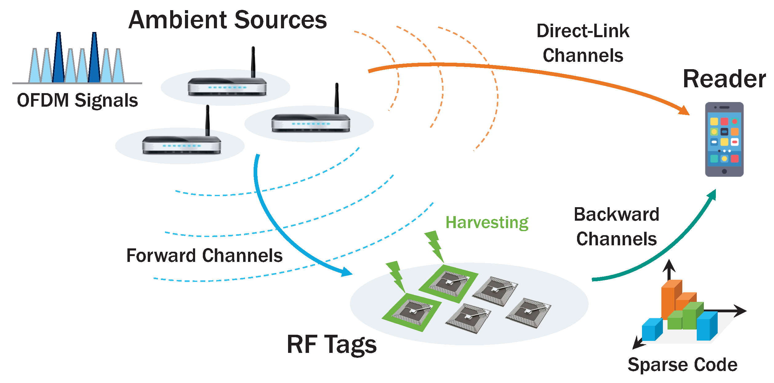
  • Direct-Link Interference: We consider separated ambient source and reader for long-range AmBC in contrast to the short-range AmBC with colocated source and reader in [24]. In addition, to effectively cancel DLI, we utilize frequency-domain structure of OFDM carriers from multiple ambient sources, which can be an extension of the works [11,12,25] with single ambient source.
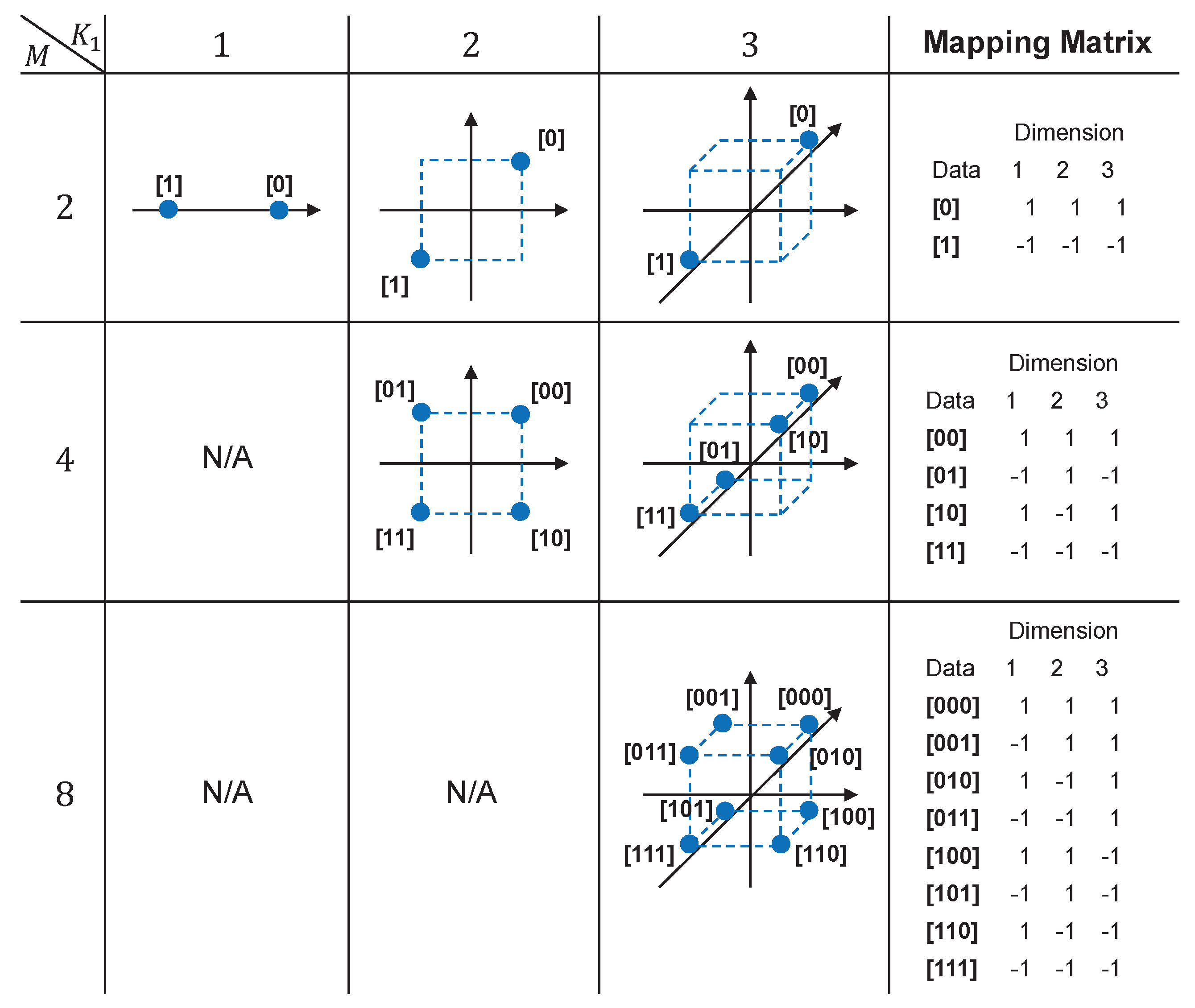
  • Multi-Dimensional Signaling: We extend sparse codes [24] designed for specific cases (i.e., M 8 , K 1 = 2 ) in low dimension to generalized cases (i.e., 2 M < , 1 K 1 < ) in multi-dimensional signal space. Also, to optimize multi-dimensional signal constellation, we propose a heuristic algorithm which effectively maximizes the minimum Euclidean distance among constellation points. Simulation results demonstrate the feasibility of high-order modulation for the RF tags with small form-factor and BPSK backscatter modulators.
  • Reflection Coefficient Projection and Expansion: We modify the low number of projection methods [26,27] considered in active radios with oscillators to support passive ambient backscatter radios implemented via reflection and OFDM carriers from ambient sources. The proposed method can be applied to general AmBC scenarios, extending the previous work [24].
To the best of the authors’ knowledge, a generalized construction of multi-dimensional signal space using sparse codes for both the long-range and high-rate AmBC has not yet been proposed in the literature. The rest of the paper is organized as follows. Section 2 describes the AmBC system model including sources and channels. The sparse codes at the tags will be discussed in Section 3 and the detection scheme at the reader is described in Section 4. Numerical results in Section 5 demonstrate the feasibility of the multi-dimensional signalling for AmBC. Finally, concluding remarks are given in Section 6.

2. System Model

2.1. Notation

Matrices (vectors) are denoted with upper (lower) case bold-face letters (e.g., A or a ); the operator · H denotes the Hermitian; the operator · denotes the vector norm; the operator ⊗ denotes the Kronecker product; the operator ∘ denotes the Hadamard product, the set of real, complex and binary numbers are respectively denoted by R , C and B ; the vector 1 k denotes all-one column vector with size k and the vector 0 k denotes all-zero column vector with size k; the operator p A denotes the probability of the event A . the operator E · denotes statistical expectation; CN ( μ , σ 2 ) denotes the circularly symmetric complex normal distribution with mean μ and variance σ 2 ; the function I { x } denotes the indicator function of the event x.

2.2. Ambient Source Model
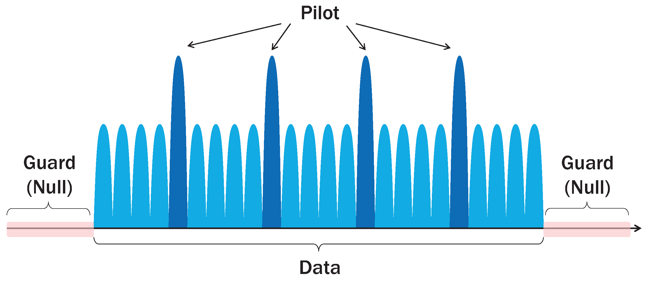
We consider the multi-dimensional sparse-coded ambient backscatter communication (MSC-AmBC) network embedded with U multiple ambient sources emitting RF signals which can be utilized for AmBC, N concurrent RF tags employing sparse codes to represent M-ary data in multi-dimensional signal space and a single reader separated from the sources as depicted in Figure 1. Typical example of the RF sources includes TV stations [1,2] in digital video broadcasting (DVB) network, Wi-Fi AP [3,12] in wireless local area network (WLAN), small-cell base stations in beyond 4G/5G [28,29,30], all of which are not dedicated to the reader. Among various modulations, the most common scheme employed here is an orthogonal frequency division multiplexing (OFDM).
In an OFDM carrier, there are L multiple subcarriers with low power (e.g., +20 dBm in Wi-Fi) in frequency domain for high-rate data transmissions against frequency-selective channel. Specifically, L subcarriers in ambient source signals can be classified into 3 groups of subcarriers: data, pilot, guard (null). At ambient source u = 1 , , U for time slot (OFDM symbol period) k = 1 , , K , these subcarriers can be summarized as
  • Data Subcarriers: There are L D data subcarriers with M D -ary modulation. Symbols in data subcarriers are denoted by ρ D ( l , u , k ) A D , l Φ D where A D is the alphabet set of data subcarriers with cardinality | A D | = M D and Φ D the index set of data subcarriers with cardinality | Φ D | = L D . These subcarriers are used to transmit data intended for legacy receivers but unknown to the reader which has to decode backscattered signals from multiple tags.
  • Pilot Subcarriers: There are L PI pilot subcarriers with M PI -ary modulation. Similar to the above, symbols are denoted by ρ PI ( l , u , k ) A PI , l Φ PI where A PI is the alphabet set of pilot subcarriers with cardinality | A PI | = M PI and Φ PI the index set of pilot subcarriers (e.g., 12, 26, 40, 54 in 802.11g Wi-Fi) with cardinality | Φ PI | = L PI . The pilot subcarriers are required for channel estimation in the legacy OFDM system and generated by known sequences. When the preamble of OFDM frame is received by the reader, the symbols in these subcarriers can be efficiently acquired at the reader. Hence, the pilot subcarriers can act as spreading sequences [11,12,25] enabling reliable AmBC for RF tags.
  • Guard Subcarriers: There are L G guard subcarriers with index l Φ G where Φ G is the index set of guard subcarriers. These subcarriers contain no power to prevent inter-carrier interference from adjacent OFDM carriers and not related to the AmBC systems.
Accordingly, the frequency-domain ambient source signals are composed of the active L A = L D + L PI subcarriers and the inactive (null) L G subcarriers as depicted in Figure 2. Thus, the total L = L A + L G subcarriers whose indices belong to Φ = Φ D Φ PI Φ G are generated in each source u during OFDM symbol period T s . Since there are U OFDM carriers actively generated from sources and N OFDM carriers passively reflected from RF tags, there exist U + N 2 multiple OFDM carriers, further complicating detection of AmBC signals (i.e., U + N = 2 is common in the conventional AmBC system design [1,2,3,5,11,12,25,31,32]). For the k-th time slot, frequency-domain ambient source signal s ˙ u , k C L × 1 can be represented by
s ˙ u , k = [ s ˙ u , k ( 1 ) s ˙ u , k ( l ) s ˙ u , k ( L ) ] T , where s ˙ u , k ( l ) = ( 1 ζ ) L A L D σ s ρ D ( l , u , k ) , if l Φ D , ζ L A L PI σ s ρ PI ( l , u , k ) , if l Φ PI , 0 , if l Φ G ,
where 0 < ζ < 1 denotes the power allocation ratio [33] for the pilot subcarriers, σ s 2 the average power of the source symbols, and we assume equal power allocation for each set of subcarriers Φ PI , Φ D . In the next step, the frequency-domain OFDM signal s ˙ u , k is transformed into the time-domain signal s u , k by inverse discrete Fourier transform (IDFT) followed by insertion of the cyclic prefix (CP) of length L CP . To do this, we define unitary IDFT matrix Ω (i.e., Ω H Ω = I L ) and CP insertion matrix Ξ + as [25,34]
Ω = { ω l , l } C L × L , where ω l , l = 1 L e j 2 π L ( l 1 ) ( l 1 ) ,
Ξ + = [ I CP I L ] B L ˜ × L ,
where I L denotes the identity matrix of size L, I CP is generated by picking last L CP rows from the matrix I L , and the length of the time-domain signal is given by L ˜ = L + L CP [12]. As a result, the transformed signal s u , k can be expressed by [25,34]
s u , k = Ξ + Ω s ˙ u , k C L ˜ × 1 ,
where the signal s u , k is sampled at the reader for every T c = T s L ˜ period (chip duration).

2.3. Channel Model

Once the U ambient signals are generated by the sources, they can be excitation signals for N RF tags for AmBC and backscattered to the reader for K time slots. In AmBC, channels among the sources and the reader can be characterized as follows:
Direct-link Channels: They denote the direct-links from sources to the reader in AmBC and can be harmful interferences for decoding tag data when these channels are strong [2,3,11,12]. Let d S u R denote the distance from the source u = 1 , , U to the reader and L h 0 , u indicate the number of multipaths [25] (e.g., they include asynchronism, Doppler shift, propagation delay and so on). Then the impulse responses of the direct-link channels for every sampling period T c are represented by
h 0 , u = [ h 0 , u ( 1 ) , , h 0 , u ( L h 0 , u ) ] T C L h 0 , u × 1 , h 0 , u ( l ) CN 0 , σ h 0 , u 2 L h 0 , u , σ h 0 , u 2 = G s A e 4 π d S u R 2 ,
where G s is the antenna gain and A e the effective aperture (e.g., A e 0.0012 in 2.4 GHz) [35]. Since the ambient signals are wideband (e.g., 20 MHz) and experience frequency-selective fading, the frequency-domain channel representation using discrete Fourier transform (DFT) is necessary for analysis, which is given by
h ˙ 0 , u = Ω 1 [ h 0 , u T O L L h 0 , u T ] T C L × 1 .
On the other hand, the time-domain direct-link channels considering multipath components can be obtained by [25]
H 0 , u + = l = 1 L h 0 , u h 0 , u ( l ) J L ˜ + l 1 C L ˜ × L ˜ , H 0 , u = l = 1 L h 0 , u h 0 , u ( l ) J L ˜ L ˜ l + 1 C L ˜ × L ˜ ,
where the matrix J L ˜ + B L ˜ × L ˜ denotes the Toeplitz forward shift matrix whose first column is given by [ 0 , 1 , 0 , , 0 ] T while the matrix J L ˜ B L ˜ × L ˜ the Toeplitz backward shift matrix whose first row is given by [ 0 , 1 , 0 , , 0 ] [34].   
Forward Channels: They denote the links from the ambient sources u = 1 , , U to the tags n = 1 , , N . These channels are related to efficiency of ambient energy harvesting and thus determine the number of active RF tags connected to the reader. Similarly, the impulse responses of the forward channels can be formulated as
f n , u = [ f n , u ( 1 ) , , f n , u ( L f n , u ) ] T C L f n , u × 1 , f n , u ( l ) CN 0 , σ f n , u 2 L f n , u , σ f n , u 2 = G s A e 4 π d S u T n 2 ,
where d S u T n denotes the distance from the source u to the tag n. The frequency-domain representation of the channels can be obtained by
f ˙ n , u = Ω 1 [ f n , u T O L L f n , u T ] T C L × 1 .
Likewise, the time-domain representation is given by
F n , u + = l = 1 L f n , u f n , u ( l ) J L ˜ + l 1 C L ˜ × L ˜ , F n , u = l = 1 L f n , u f n , u ( l ) J L ˜ L ˜ l + 1 C L ˜ × L ˜ .
Backward Channels: They denote the links from the tags n = 1 , , N to the reader and associated to detection performance of AmBC in terms of the received signal-to-noise ratio (SNR) and minimum Euclidean distance of sparse codes in multi-dimensional signal space. The impulse response of the backward channels can be expressed by
g n = [ g n ( 1 ) , , g n ( L g n ) ] T C L g n × 1 , g n ( l ) CN 0 , σ g n 2 L g n , σ g n 2 = G s A e 4 π d T n R 2 ,
where d T n R denotes the distance from the tag n to the reader. The channels in frequency domain are represented by
g ˙ n = Ω 1 [ g n T O L L g n T ] T C L × 1 .
In the similar way, the time-domain representation is given by
G n + = l = 1 L g n g n ( l ) J L ˜ + l 1 C L ˜ × L ˜ , G n = l = 1 L g n g n ( l ) J L ˜ L ˜ l + 1 C L ˜ × L ˜ .
When the time-domain ambient signals s u , k , u = 1 , , U , k = 1 , , K are emitted from the sources, these signals can be received by N multiple tags after faded by the forward channels f n , u . Hence, the incident signal at the tag’s antenna can be expressed by [25]
y k , n = u = 1 U F n , u + s u , k + F n , u s u , k 1 C L ˜ × 1 .
It is noteworthy that there are U OFDM carriers interfering with each other as well as intersymbol interference (ISI) s u , k 1 from the previous ( k 1 ) -th time slot rather than a single carrier from frequency-flat fading channel. Then, these carriers y k , n are utilized for both the ambient energy harvesting and data modulation at the tags. In the following section, we discuss a design criteria of the proposed sparse codes toward these goals.

3. Sparse Codes

3.1. Preliminary: Limitations in Conventional Backscatter

In the previous section, we considered the dense network scenarios with U multiple sources as well as N multiple tags. When there are multiple tags backscattering data to the reader, the most common and simplest method of data uploading is using TDMA [32]. In TDMA where K time slots are allocated to N tags, the number of time slots required for data uploading is K N and the duty cycle of each tag is D 1 K . Unfortunately, there are fundamental limitations in TDMA, which prohibit application of AmBC for low-power Internet of things (IoT) network with massive number of sources and tags.
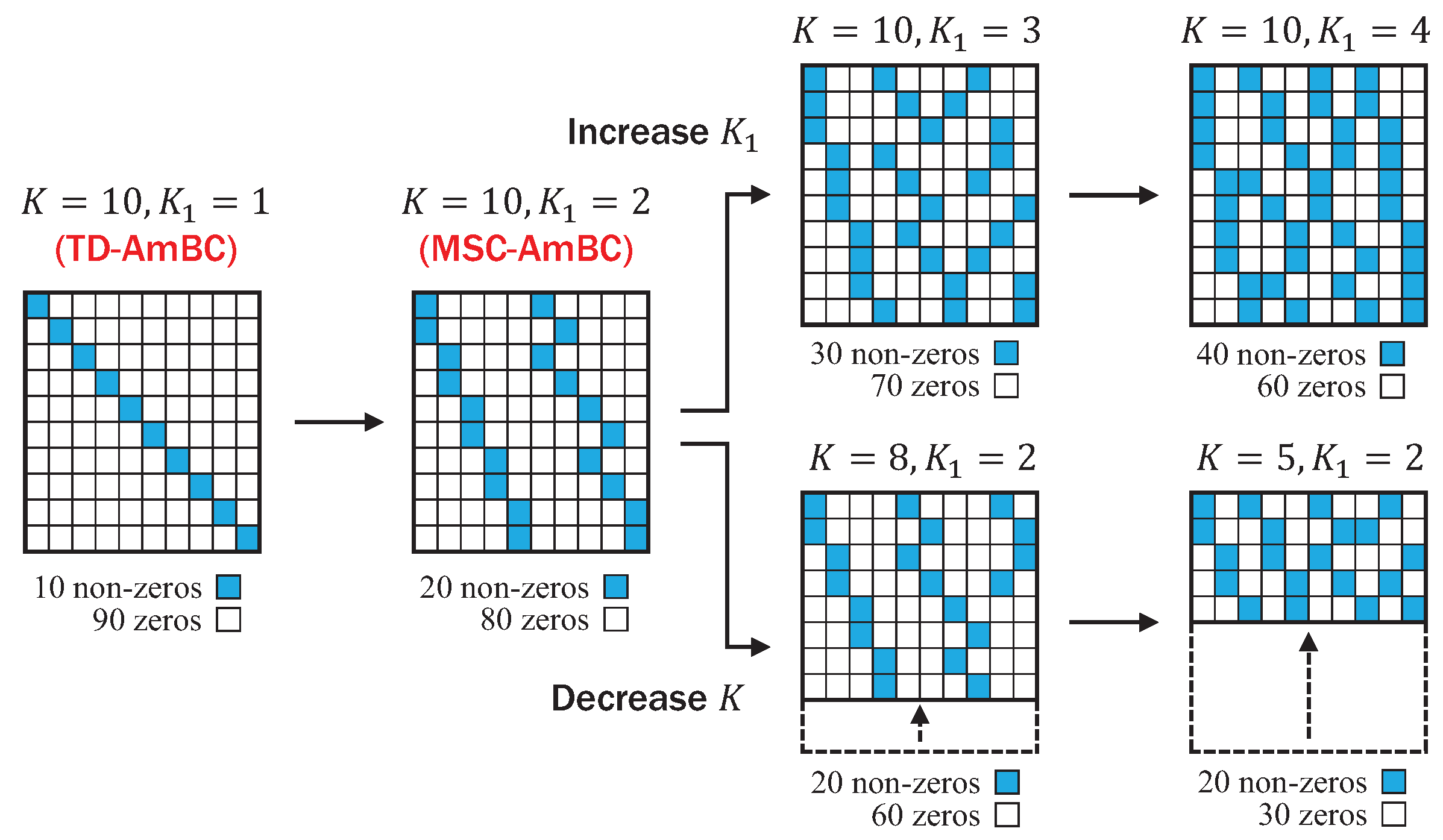
  • Short-Range Communication: TDMA-based AmBC (TD-AmBC) system has a short communication range because the ambient backscatter signals received at the reader are significantly attenuated by both the forward channels and backward channels. By poor propagation properties in the composite forward-backward channels, or dyadic backscatter channels [6,7], backscatter signals are too weak to be decoded at the reader when the distance among tags and the reader increases. Furthermore, simple repetition coding by increasing the number of time slots K (equivalently, symbol period) [3,5] in the TD-AmBC is not sufficient enough to combat channel fading in practice. Besides, in the TD-AmBC, only one tag is activated in a time slot for backscatter communication and the rest of N 1 tags remain idle (or harvesting energy). By adopting orthogonal multiple access (OMA) among tags in the TD-AmBC, the duty cycle is limited to D 1 / N . If a massive number of tags N 1 are connected to the reader, such as in low-power wide area network (LP-WAN), the duty cycle D goes to zero and the data rate of individual tag diminishes accordingly. Hence, by the channel and connectivity issues, the TD-AmBC is limited to short-range applications, typically less than few meters [1,2,3,5].
  • Low-Rate Communication: In the TD-AmBC, the data rates of tags decrease when the channel conditions are bad, or there are multiple concurrent backscatter signals from tags to the reader as we discussed above. In addition, due to hardware limitation of the tags with small form-factor, tags’ data is modulated in low-order modulation schemes, typically ranging from M = 2 (e.g., on-off keying (OOK) [1,2,5] to M = 16 (e.g., 16-PSK [3], 16-QAM [20]). However, to implement high-order backscatter modulators, we should add a series of load impedances and corresponding RF switches to the tags’ circuit, which inevitably increases installation costs and form-factor of the tags. As such, the TD-AmBC is limited to low-rate applications in practice.
To tackle these limitations, we first introduce the distinct characteristics of sparse codes in the following subsection.

3.2. Characteristics of Sparse Codes

Sparse codes [23,26,27,36,37] are part of a coding scheme based on the sparsity inherent in batteryless RF tags. For example, when there are N tags in a backscatter network with duty cycle D < 1 , the expected number of active tags in an arbitrary time slot is N D < N , which is a small portion, so that the MAI among tags is only affected by a fewer number of tags rather than the entire N. By using this sparsity property (i.e., only a small portion of tags are overlapped in time domain) originated from the duty-cycling operation in batteryless RF tags [9], it is possible for multiple tags to achieve long-range and high-rate communications with minimal interference [23]. Furthermore, sparse codes can support massive IoT connectivity by overloading λ = N K tags per time slot in a non-orthogonal manner. Sparse code multiple access (SCMA) is classified into code-domain NOMA and regarded as one of the prospective radio access techniques in 5G and IoT networks. Especially, when the sparse codes are applied to AmBC, there are several powerful characteristics which can lead to the vision of the massive IoT networks.
  • Multi-Dimensional Signalling: In contrast to the TD-AmBC with duty cycle D 1 N , sparse-coded AmBC can prolong the duty cycle of RF tags to be D 1 N by allowing non-orthogonal transmissions among tags. When sparse codes are applied to tags, a codeword encoded by each tag spans for K N compressed time slots by utilizing sparsity and there exist 2 K 1 K non-zero elements and K K 1 zero elements contained in each codeword. By the definition of the duty cycle D = K 1 K 1 N , sparse codes can prolong the duty cycle of RF tags effectively. Especially, the parameter K 1 denotes the dimension of signal constellation which is related to the duty cycle D. Therefore, based on the sparsity of codewords, ambient backscatter signals can be represented in higher dimension for achieving diversity gain [38] by increasing the duty cycle of RF tags. As a result, the multi-dimensional signalling can support long-range AmBC of few tens of meters, enabling the vision of LP-WAN [14].
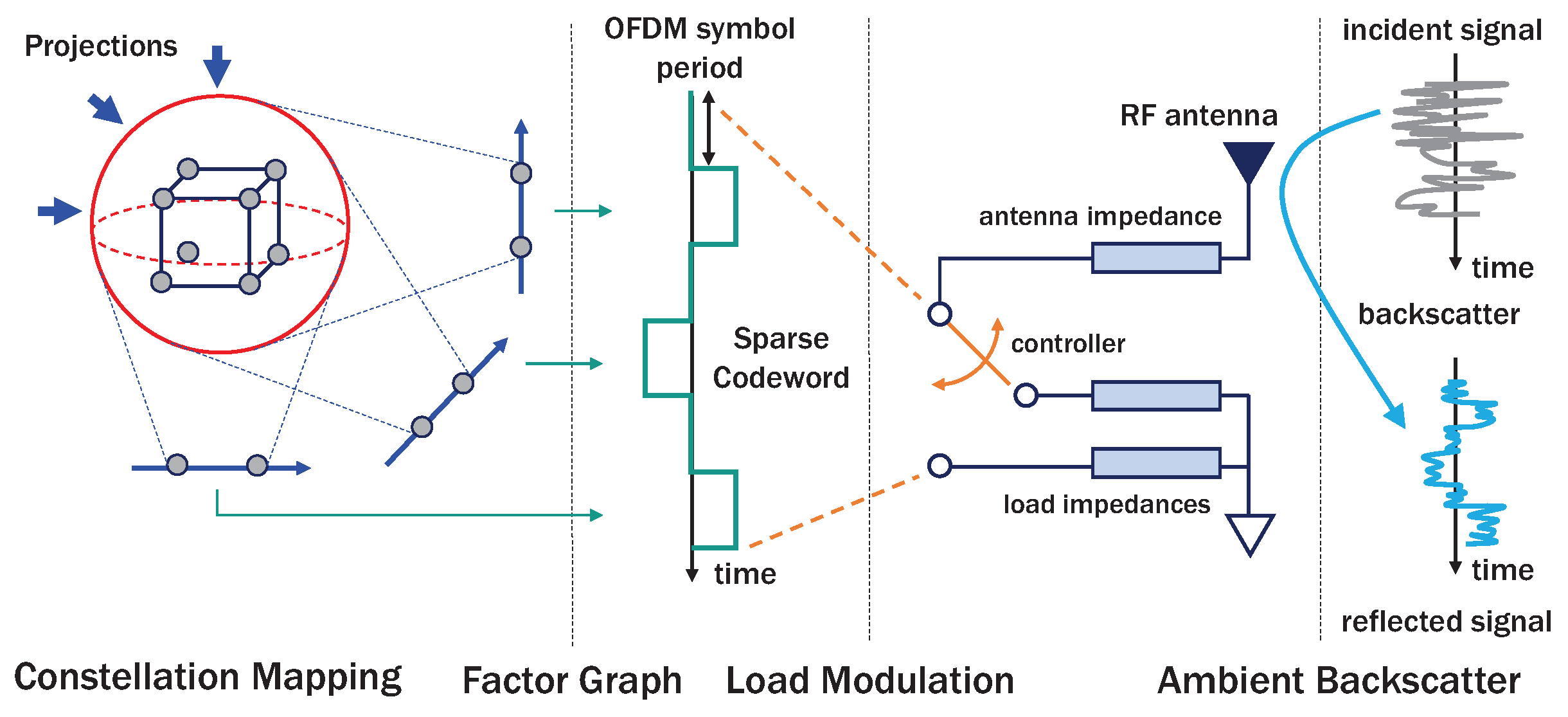
  • Feasibility of High-Order Modulation: Instead of manufacturing the customized M-ary backscatter modulators [3,20,21,22] in the conventional TD-AmBC, sparse codes can implement M-ary modulation at commercial RF tags with small form-factor by employing binary PSK (BPSK) backscatter modulator. Based on the principle of the low number of projection method [26,27], M-ary constellation points can be projected onto M ˜ = 2 reflection coefficients at the tags, and then decoded at the reader by a low-complexity iterative message passing algorithm (MPA). Theoretically, any high-order modulation (e.g., M 32 ) can be implemented in AmBC as long as the dimension K 1 is large enough to span M 2 K 1 constellation points. Thus, sparse codes can also achieve high-rate AmBC with reasonable installation costs for massive IoT.
Figure 3 illustrates our proposed MSC-AmBC modulation at RF tags. To generate sparse codes, M-ary data from N tags are modulated by a K 1 -dimensional constellation mapping function, and then spread into a K-length codeword using a factor graph. Then, sparse codewords are modulated by switching M ˜ M load impedances and backscattered to the reader. In the following subsection, we discuss a design criteria of the constellation mapping function as well as the factor graph.

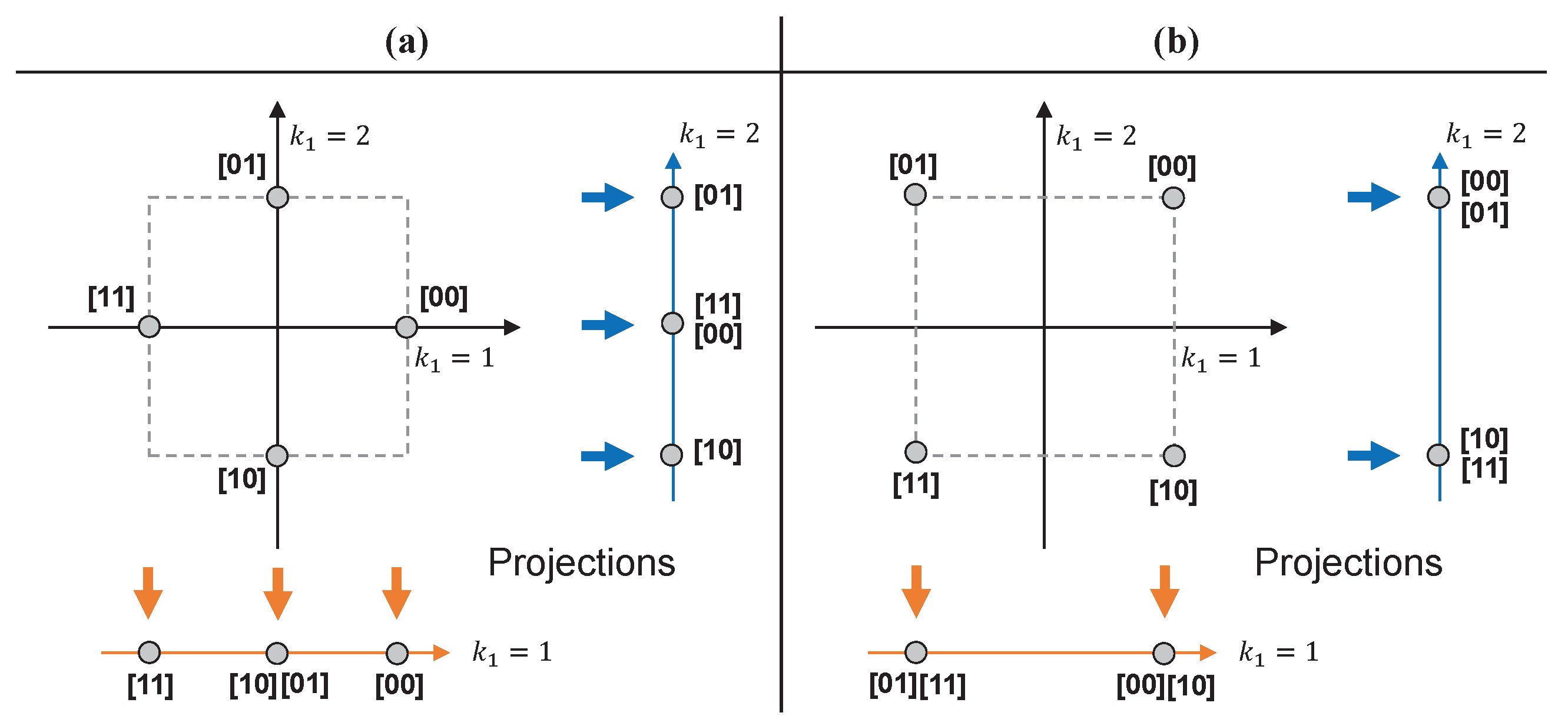
3.3. Design of Constellation Mapping Function

When the tags have data to transmit to the reader, they can generate V = log 2 M bits data d n = [ d n , 1 , , d n , V ] { d ˜ ( 1 ) , , d ˜ ( m ) , , d ˜ ( M ) } , where d ˜ ( m ) = [ d ˜ 1 ( m ) , , d ˜ V ( m ) ] B 1 × V , and modulate constellation symbols in K 1 -dimensional signal space with power reflection ratio 0 < α 1 . Typically, AmBC modulation is implemented by BPSK modulator with 2 M ˜ 3 < M states of reflection coefficients. Based on the BPSK backscatter modulator, we can define a backscatter symbol vector b C M ˜ × 1 as
b = [ b ( m ˜ 1 ) , b ( m ˜ 2 ) ] T = α [ 1 , 1 ] T , for M ˜ = 2 , b ( m ˜ 1 ) , b ( m ˜ 2 ) , b ( m ˜ 3 ) ] T = α [ 1 , 0 , 1 ] T , for M ˜ = 3 .
Choice of the number of projection points M ˜ depends on the energy efficiency, complexity and BER performance. Figure 4 shows the signal constellations for M ˜ = 2 , 3 . There are M = 4 contellation points with minimum Euclidean distance d min = 2 α and M ˜ = 3 projection points [26,27] in the dimension k 1 = 1 , 2 (i.e., horizontal and vertical axes) in Figure 4a. On the other hand, in Figure 4b, d min = 2 α and only M ˜ = 2 projection points are present in each dimension k 1 . By choosing M ˜ = 2 , we can achieve the larger minimum Euclidean distance among constellation points and the lower decoding complexity of order O ( M ˜ N 1 ) where N 1 is the number of interfering tags in each dimension. Besides, since fewer points are required in each dimension, the algorithm complexity for optimizing the constellation mapping function will be lowered, so the mapping can be systematically optimized for general values of K 1 and M. For this reason, we choose M ˜ = 2 for optimal design of the constellation mapping function, which is beneficial in terms of the Euclidean distance and encoding/decoding complexity.
To design an optimal constellation mapping function, we define a constellation mapping matrix F ˜ = [ f ˜ 1 T , , f ˜ m T , , f ˜ M T ] T C M × K 1 with K 1 log 2 M . Then the row vector f ˜ m = [ f ˜ m ( 1 ) , , f ˜ m ( k 1 ) , , f ˜ m ( K 1 ) ] C 1 × K 1 denotes the constellation point in K 1 -dimensional signal space. Then the optimization problem for maximizing the minumum Euclidean distance among the constellation points can be formulated as
max { f ˜ m } m = 1 , , M min m 1 m 2 f ˜ m 1 f ˜ m 2 2 s . t . f ˜ m ( k 1 ) { b ( m ˜ 1 ) , b ( m ˜ 2 ) } , m = 1 , , M , k 1 = 1 , , K 1 .
To solve the above optimization problem, we derive the constellation mapping matrix F ˜ with m = 2 , 4 , 8 and K 1 = 1 , 2 , 3 as depicted in Figure 5. By placing some constellation points in the lattice with Gray code labelings, we can observe the following remarks on design of the constellation mapping matrix F ˜ .
Remark 1.
The M × K 1 constellation mapping matrix satisfies following properties:
  • In the k 1 = 1 , , V -th column, a vector e k 1 = b 1 2 k 1 1 is repeated M 0 = M 2 k 1 times.
  • For k 1 = V + 1 , , K 1 , the k 1 -th column is equal to the k 0 -th column where k 0 = mod ( k 1 1 , V ) + 1 .
For example, if M = 4 and K 1 = 3 in Figure 5, the first column of the matrix is generated by alternating 1, −1 of period 1, and the second column of the matrix is generated by those of period 2. The third column is equal to the first column satisfying the second property in Remark 1. Hence, based on Remark 1, we propose an algorithm for optimizing the constellation mapping matrix as depicted in Algorithm 1. Using the low-complexity heuristic algorithm with arbitrary values of K 1 and M, we can easily optimize the constellation mapping function for both high-rate (e.g., M = 16 , 32 , 64 , ) and long-range (e.g., K 1 = 4 , 5 , 6 , ) AmBC systems.
Algorithm 1 Constellation Mapping Matrix Optimization
1:
input the dimension K 1 , the modulation order M and the backscatter symbol vector b .
2:
initialize the mapping matrix F ˜ = [ f 1 , , f k 1 , , f K 1 ] .
3:
for k 1 { 1 , , K 1 } do
4:
    if k 1 V then
5:
        calculate e k 1 = b 1 2 k 1 1 and M 0 = M 2 k 1
6:
        calculate f k 1 = [ e k 1 T , , e k 1 T repeat M 0 times ] T
7:
    else
8:
        calculate k 0 = mod ( k 1 1 , V ) + 1 .
9:
        calculate f k 1 = f k 0
10:
    end if
11:
end for
12:
output the mapping matrix F ˜ = [ f 1 , , f k 1 , , f K 1 ]

3.4. Design of Factor Graph

The role of the constellation mapping function is to modulate M-ary data into K 1 log 2 M -dimensional symbols which can easily be generated by simply switching M ˜ load impedances at N tags. In the next step, K 1 -dimensional symbols are spread to K-dimensional sparse codewords to minimize the MAI among N tags and to enable NOMA. To do so, we should determine the system parameters K 1 and K to meet the following condition as
log 2 M K 1 K N , where K K 1 N .
Given K 1 and K satisfying the above condition, we can design a factor graph G ˜ 0 = { g ˜ 0 , k , n } k , n B K × N with K 1 non-zero elements in each column as depicted in Figure 6. For instance, the conventional TD-AmBC can be considered as a special case of sparse codes with K 1 = 1 with orthogonal allocation of non-zeros in codebooks, which is not spectrally efficient as the tags backscatter for a small fraction of time only and remain idle for the rest of time. On the other hand, for K 1 2 , there are K 1 -fold increase in the duty cycle of tags D = K 1 K and N 1 = N K 1 K -fold increase in the spectral efficiency (i.e., there are N 1 non-zeros in each row (time slot)). It is noteworthy that prolonging the duty cycle of tags by increasing K 1 can constitute the multi-dimensional signal space which is beneficial for achieving both diversity gain K 1 for M = 2 or multiplexing gain V = log 2 M for M 4 . In addition, since codebooks are generated with low-density (sparse), the length of codewords K can be decreased to overload a massive number of tags N K for boosting the data rate of AmBC. As shown in the Figure 6, the time slots required for N = 10 tags can be compressed to K = 5 , achieving the overloading gain λ = N K = 2 . However, the parameters K 1 and K can degrade the energy harvesting efficiency of tags by controlling D. As D increases, the tags should be activated for a long period of time when uploading their data to the reader, consuming more power at their RF circuits. Therefore, these parameters should be carefully determined to coordinate the communication range, data rate, energy harvesting efficiency of the AmBC system.
Given N, K 1 and K, the factor graph is formed to minimize the number of interfering tags in every time slot by designing the sparse factor graph matrix G ˜ 0 . The optimization problem of G ˜ 0 can be formulated as [39]
min G ˜ 0 B K × N , d ^ > 0 max n = 1 N g ˜ 0 , k , n ϵ d ^ s . t . k = 1 K g ˜ 0 , k , n = K 1 , n = 1 , , N , k = 1 K | g ˜ 0 , k , n 1 g ˜ 0 , k , n 2 | d ^ , n 1 n 2 , n 1 , n 2 = 1 , , N ,
where ϵ > 0 is the penalty coefficient and d ^ the minimum Euclidean distance among column vectors in the matrix G ˜ 0 . The near-optimal algorithm for design of the factor graph can be found in [39], and the codebooks { B 0 ( m ) } m { 1 , , M } can be generated from the constellation mapping matrix F ˜ and the factor graph G ˜ 0 . Specifically, in the m-th codeword B 0 ( m ) = { b ˜ 0 , k , n ( m ) } k , n , the element b ˜ 0 , k , n ( m ) can be calculated by
b ˜ 0 , k , n ( m ) = f ˜ m ( k 1 ) , if g ˜ 0 , k , n = 1 , k 1 = k = 1 k g ˜ 0 , k , n , 0 , otherwise .

3.5. Duty-Cycling Operation

As sparse codes are applied to batteryless passive tags, the design of the codebook affects the energy state of RF tags relying on the duty-cycling operation. For the duty-cycling operation, the incident power received at the antenna of tag n can be expressed as
E n = E k = 1 K y k , n 2 .
Then the energy harvesting (EH) constraint can be formulated as [40]
E n θ = P c η ( 1 β ) , P c = R s σ c 2 β = D σ b 2 , σ b 2 = 1 M K 1 m = 1 M f ˜ m 2 = α ,
where σ c 2 is the energy per symbol (e.g., 0.58 pJ/symbol [18]), η the energy harvesting efficiency (e.g., 25% [41]), σ b 2 the average backscatter symbol power, and R s = 1 T s represents the backscatter symbol rate. It is noteworthy that since there are U multiple ambient sources with the OFDM modulation, tags can harvest sufficient energy from these sources nearby in dense network scenarios and be activated to upload data to the reader. The state of tag a = [ a 1 , , a N ] B 1 × N (i.e., 0: idle, 1: active) with EH threshold θ can be obtained by
a n = I { E n θ } , for n = 1 , , N .
Given the state a , the reflection coefficients and backscattered signals at RF tag n = 1 , , N over L ˜ OFDM samples in time slot k = 1 , , K can be represented by
x k , n = Γ k , n y k , n C L ˜ × 1 , where Γ k , n { 0 } , if a n = 0 , b ˜ 0 , k , n ( m ) , if a n = 1 .
Then, the N sparse-coded AmBC signals over K time slots are backscattered to the reader. In the following section, we discuss a scheme for detecting these signals when both the OFDM structure and sparse codebooks are known to the reader.

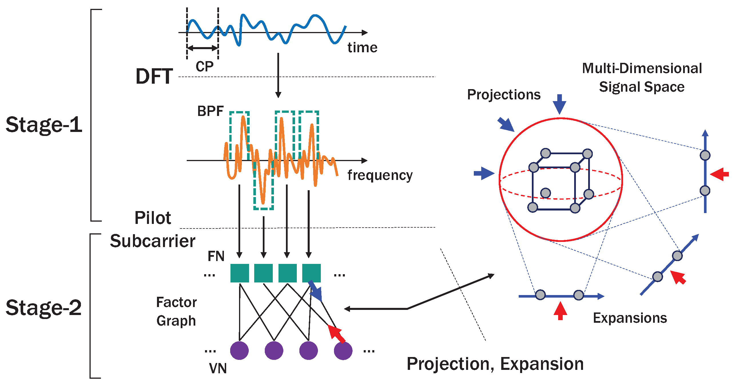
4. Two-Stage Detection

Figure 7 shows the structure of MSC-AmBC detection at the reader. Specifically, the detection is composed of two stages which are designed for utilizing the inherent characteristics of the sources (i.e., OFDM pilot subcarriers) and tags (i.e., sparsity, duty-cycling operation). In the following subsections, we describe a series of signal processing techniques that enable successful detection of AmBC signals.

4.1. Stage-1: Utilizing OFDM Structure

At the reader, when the AmBC signals x k , n are received from the backward channel G n + , G n , these signals are interfered by the stronger source signals s u , k with the direct-link channel H 0 , u + , H 0 , u . The superposition signal r k can be represented by [25]
r k = u = 1 U H 0 , u + s u , k + H 0 , u s u , k 1 direct link interferences + n = 1 N G n + x k , n + G n x k 1 , n backscattered signals + w k C L ˜ × 1 ,
where w k is the circularly symmetric additive white Gaussian noise (AWGN) with variance σ n 2 . As the received signals are affected by the direct-link, forward and backward channels, we define their composite channels h ˙ n , u as
h ˙ n , u = L f ˙ n , u g ˙ n , if n 0 L h ˙ 0 , u , if n = 0 , , n = 0 , , N , u = 1 , , U ,
where the case of n 0 represents the composite forward-backward channels while the case of n = 0 the direct-link channels. Then, the time-domain signal r k is transformed into the frequency-domain signal r ˙ k after removing the CP of length L CP and using discrete Fourier transform (DFT), that is [25]
r ˙ k = Ω 1 Ξ r k C L × 1 ,
where Ξ = [ 0 L , L CP , I L ] B L × L ˜ is the CP removal matrix with the all-zero matrix 0 L , L CP of size L × L CP . It is noteworthy that the ISI from the previous time slot k 1 can easily be cancelled by removing the CP under the condition, given by [25]
max max n , u ( L f n , u + L g n ) , max u ( L h 0 , u ) 1 L CP .
Since the ranges of the AmBC signals are much shorter than those of the OFDM signals, the above condition can easily be satisfied. There are L PI pilot subcarriers with index l Φ PI = [ ϕ 1 , , ϕ L PI ] , so the band-pass filter (BPF) matrix to extract the L PI pilot subcarriers can be expressed by
Δ = { δ l PI , l } B L PI × L , where δ l PI , l = I { l = ϕ l PI } , l PI = 1 , , L PI , l = 1 , , L .
The output of the BPF is therefore expressed by
r ˜ k = Δ r ˙ k = n = 0 N u = 1 U h ˜ n , u s ˜ u , k Γ k , n + w ˜ k
= n = 0 N ψ k , n Γ k , n + w ˜ k C L PI × 1 ,
where h ˜ n , u = Δ h ˙ n , u C L PI × 1 , s ˜ u , k = Δ s ˙ u , k C L PI × 1 , and Γ k , 0 = 1 for notational convinience. We can observe that L PI pilot subcarriers are required for detecting the backscattered signals, and these pilot sequences can be known to the reader as the reader receives the preamble signals from U ambient sources [3]. Besides, by the virtue of sparsity of the backscattered signals, the channel ψ k , n can be efficiently obtained by compressed sensing (CS) based channel estimations [42]. Hence, the DLI contained in the pilot subcarriers can be cancelled out, that is
z k = r ˜ k ψ k , 0 C L PI × 1 .
It is remarkable that there are L PI pilot subcarriers per OFDM symbol, and there are K ˜ = K L PI pilot signals in the entire signal. Therefore, we should expand the factor graph G ˜ 0 and the codebook { B 0 ( m ) } m { 1 , , M } , which can be achieved by
G ˜ = G ˜ 0 1 L PI C K ˜ × 1 , B ( m ) = B 0 ( m ) 1 L PI C K ˜ × N , m = 1 , , M .
Equivalently, the expanded factor graph has K ˜ factor nodes (FNs) and N variable nodes (VNs) with degree K 1 . In the following subsection, we describe the MPA with the number of projection points M ˜ = 2 to support high-rate and long-range AmBC.

4.2. Stage-2: Utilizing Sparse Code Structure

In sparse codes, a low-complexity MPA [43,44] can be used to detect N tags’ data from K ˜ pilot signals using the iterative projection and expansion method as described in Figure 7. We first vectorize the received signals and channels of size L PI × K to generate the column vectors of K ˜ × 1 as follows:
z = [ z 1 , , z K ˜ ] T = [ z 1 T , , z K T ] T C K ˜ × 1 ,
ψ n = [ ψ 1 , n , , ψ K ˜ , n ] T = [ ψ 1 , n T , , ψ K , n T ] T C K ˜ × 1 .
To use the information projection method, we define the dimension indicator function (that outputs the indices of dimension from K 1 -dimensional signal space) using the factor graph G ˜ = { g ˜ k ˜ , n } k ˜ { 1 , , K ˜ } , n { 1 , , N } as follows:
Λ ( k ˜ , n ) = i = 1 k ˜ g ˜ i , n 1 L PI + 1 { 1 , , K 1 } .
Then, based on the low number of projections, an initial information on FN k ˜ = 1 , , K ˜ and the information from VN n to FN k ˜ can be assigned to
f k ˜ { m ˜ i } i I k ˜ = 1 2 σ n 2 z k ˜ i I k ˜ ψ k ˜ , i b ( m ˜ i ) 2 , where I k ˜ = n | a n g ˜ k ˜ , n > 0 , m ˜ i = 1 , , M ˜ ,
I n k ˜ ( m n ) = ln a p n ( m n ) = 1 M , m n = 1 , , M .
In the next step, FN k ˜ passes the updated messages to its neighboring VNs with the intermediate variable which is given by
I ˜ k ˜ n { m ˜ i } i I k ˜ = f k ˜ { m ˜ i } i I k ˜ + i I k ˜ \ { n } I ¯ i k ˜ ( m ˜ i ) ,
where I ¯ n k ˜ ( m ˜ ) , m ˜ = 1 , , M ˜ denotes the projected information from VN n to FN k ˜ . Then, we propose a generalized information projection and expansion method using the constellation mapping matrix F ˜ . Distinct features of the proposed method are the generalization of the projections and expansions [26,27] for general values of M and K 1 and support of the AmBC over the pilot sequences of length K ˜ = K L PI in the OFDM carriers by newly introducing the function Λ ( k ˜ , n ) . The projected information related to the tags’ reflection coefficient b can be obtained by
•  Reflection Coefficient Projection:
I ¯ n k ˜ ( m ˜ ) = max { I n k ˜ ( m ) } m P ( m ˜ ) , P ( m ˜ ) = m | f ˜ m ( Λ ( k ˜ , n ) ) = b ( m ˜ ) , m = 1 , , M ,
where
max ( δ 1 , δ 2 ) = max ( δ 1 , δ 2 ) + ln ( 1 + e | δ 2 δ 1 | ) .
From above, P ( m ˜ ) denotes the index set of codewords projected toward the backscatter symbol index m ˜ . Hence, the updated message from FN k ˜ to VN n can be calculated by
I k ˜ n ( m ˜ n ) = max m ˜ i , i I k ˜ \ { n } I ˜ k ˜ n ( { m ˜ i } i I k ˜ ) , m ˜ n = 1 , , M ˜ .
It is noted that FNs send the compressed messages of size M ˜ M by the information projection for reducing the computational complexity of MPA. On the other hand, VNs receive the messages of size M ˜ from FNs, expand the messages to size M, and send the updated messages to FNs which are expressed by
I n k ˜ ( m n ) = ln a p n ( m n ) + I k ˜ n ( m n ) max m n , i J n \ { k ˜ } I ¯ i n ( m n ) ,
where J n = k ˜ | a n g ˜ k ˜ , n > 0 and I ¯ k ˜ n ( m n ) , m n = 1 , , M denotes the expanded information which can be obtained by
•  Reflection Coefficient Expansion:
I ¯ k ˜ n ( m n ) = I k ˜ n m ˜ n = 1 M ˜ m ˜ n I f ˜ m n ( Λ ( k ˜ , n ) ) = m ˜ n , m n = 1 , , M .
After N I iterations, the log-likelihood ratio (LLR) for the m -th most significant bit (MSB) where m = 1 , , V for tag n can be calculated as [44]
Θ n , m = ln p ( d n , m ) = 0 p ( d n , m ) = 1 = max m ¯ : d ˜ m ( m ¯ ) = 0 ( Q n ( m ¯ ) ) max m ¯ : d ˜ m ( m ¯ ) = 1 ( Q n ( m ¯ ) ) ,
where Q n ( m n ) = ln a p n ( m n ) + i J n I i n ( m n ) .
Finally, the M-ary backscatter data can be detected as
d ^ n , m = 1 , if Θ n , m 0 0 , if Θ n , m > 0 , for a n = 1 .
As we previously discussed, when the dimension of the signal space is sufficiently large, the MSC-AmBC system can enjoy long-range and high-rate communications, connecting massive low-power IoT devices to the Internet.

5. Simulation Results

In this section, we conduct numerical simulations using the MATLAB 2017b software package for performance evaluation of AmBC systems. We first provide a brief comparison of the TD-AmBC and the MSC-AmBC, and then describe practical simulation environments reflecting massive IoT networks with OFDM carriers. The effect of various system parameters and some interesting remarks in AmBC are also described in the section.

5.1. Comparison of AmBC Systems: TD-AmBC and MSC-AmBC

We evaluate the performance of our proposed MSC-AmBC system along with the conventional TD-AmBC system in OFDM networks. To do so, we summarize the AmBC system models as depicted in Figure 8 and Table 1. In general, these systems are integration of modulation, coding and detection blocks whose choices will be an important design factor for implementing high-rate and long-range AmBC system. However, to the best of the authors’ knowledge, the integrated system design is still an open and challenging area, and only low-rate or short-range AmBC systems in WLAN are available in the literature [1,2,3,5,11,12,17,25,31,32]. In these systems, for efficient suppression of the DLI and MAI, TDMA-based orthogonal transmission schemes [3,10,32] with M-ary PSK/QAM modulations [3,17,18,19,20,21,22] and maximal-ratio combining (MRC) detections [3,11,25] are the most favorable choice [3], compared to binary OOK/2-PSK modulations followed by energy detectors [1,2,3,5,11,12,32], which are susceptible to interferences and only support one-bit transmissions. Hence, the most general and practical system model representing previous works based on TDMA is denoted by the ’TD-AmBC’ system which is the baseline of numerical evaluation for comparison with our proposed MSC-AmBC system. It is noteworthy that the MSC-AmBC is more cost-efficient (i.e., only M ˜ = 2 load impedances) and more energy/spectral-efficient (i.e., extended duty cycle D = K 1 K ) than the TD-AmBC as described in Figure 8.

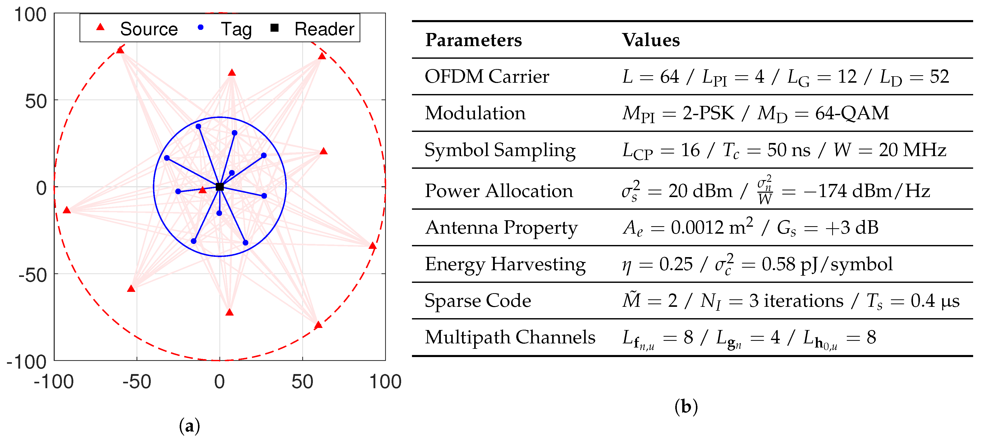
5.2. Practical Implementation of AmBC

We evaluated AmBC system in Wi-Fi OFDM networks using 2.4 GHz industrial, scientific and medical (ISM) band and following IEEE 802.11g specifications [45] as depicted in Figure 9b. Specifically, the index set of Wi-Fi OFDM subcarriers can be given by Φ PI = { 12 , 26 , 40 , 54 } (pilot subcarriers), Φ G = { 1 , 2 , 3 , 4 , 5 , 6 , 33 , 60 , 61 , 62 , 63 , 64 } (guard subcarriers) and Φ D = Φ ( Φ PI Φ G ) (data subcarriers) where Φ = { 1 , 2 , , L } . Also, the rest of the system parameters [3,18,25,41] can be found in Figure 9b. Although we selected Wi-Fi carriers for performance evaluations, the system can also be generalized to support the other OFDM networks such as LTE or DVB by simple modification of the system parameters (e.g., the pilot subcarrier set Φ PI , the CP size L CP , and the bandwidth W). Due to the wide availability of OFDM carriers and the sparsity of tags’ operations, our AmBC system can be implemented in various IoT applications including smart city, factory and farm where massive IoT connectivity is required to monitor environments and seamlessly provide useful information to the reader for intelligent decision-making for those systems. In these applications, there are U multiple ambient sources as well as N multiple RF tags transmitting data to the nearby reader whose locations are random and uncoordinated. For example, we consider the deployment scenario as shown in Figure 9a, but our model can be adapted to general IoT networks as well by simple modification of network/channel-related parameters (e.g., the number of tags N, the tag-reader distance d T n R ). When the reader such as a mobile user requests data to these RF tags within the reader’s communication range R R = 40 m, the N = 10 tags uniformly distributed inside the range can upload M-ary data based on the proposed sparse codes over U = 10 OFDM carriers. Then, the coding parameters K 1 and K are set to satisfy the energy-causality condition for the AmBC systems and used for optimal design of the constellation mapping function and the factor graph. In the MSC-AmBC, codewords are generated by M ˜ M load impedances with low number of projections in K 1 2 dimension, and then detected at the reader by the iterative projection and expansion. On the other hand, the TD-AmBC encodes codewords using M-ary PSK modulator [3] with M ˜ = M impedances modulating data in 2-dimensional signal space represented by the real and imaginary axes of the reflection coefficients and detected at the reader by the MRC [3,11,25] of pilot signals. For simplicity of simulations, we consider a single-antenna reader and no forward-error correction (FEC) codes herein, but our model can be extended to the advanced scenarios in straightforward manners to achieve long-range AmBC (e.g., increase the number of FNs at the input of MPA, and implement information exchange between inner sparse code decoder and outer FEC decoder [26]). On the other hand, to achieve high-rate AmBC, the aggregated data rate of tags can be expressed by
R ˜ b = N K R s log 2 M = λ R s log 2 M .
The performance of AmBC is numerically evaluated by Monte Carlo simulations, and the system parameters for each simulation are summarized in Figure 9b.

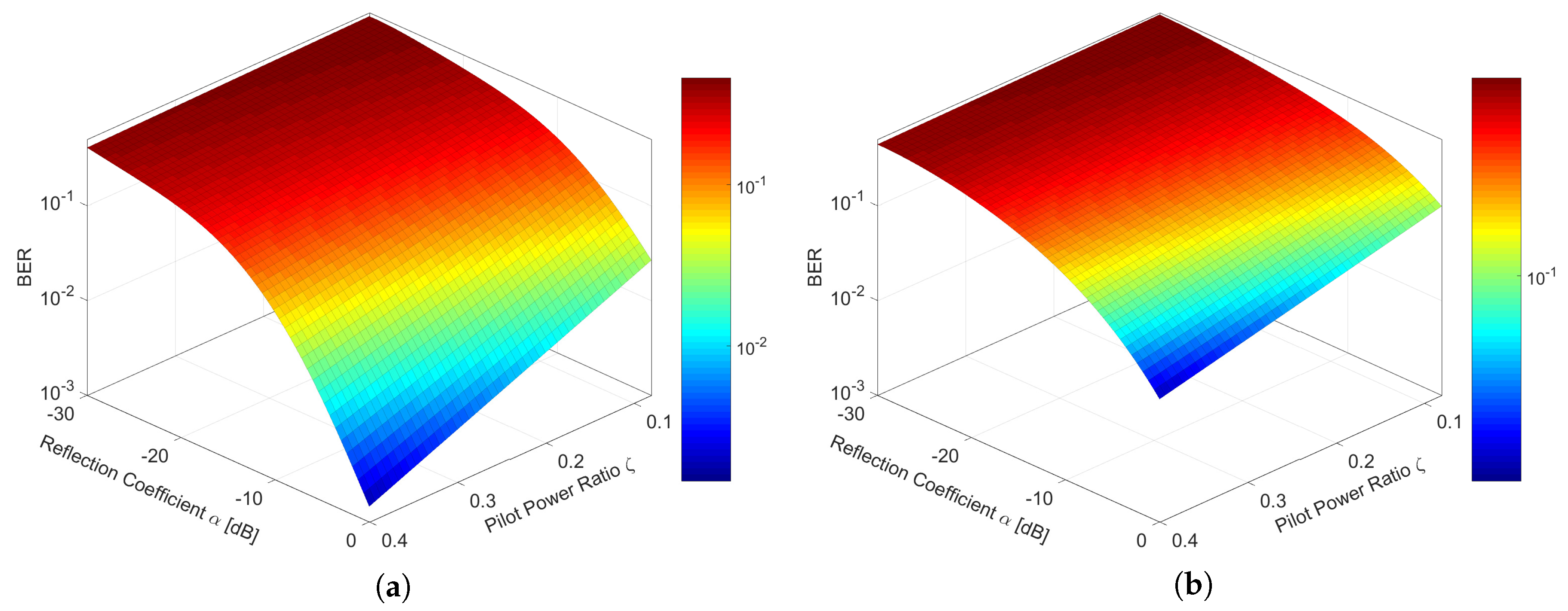
5.3. Simulation 1: Effect of OFDM Carriers

Figure 10 shows the BER performance with respect to the pilot power ratio ζ and the reflection coefficient α . The BER performance improves as the symbol power allocated in pilot subcarriers increases and tags reflect a larger amount of the incident power at their antenna. In the TD-AmBC, the reader is difficult to detect AmBC signals even if the values of ζ and α are sufficiently large because ambient OFDM carrier signals are not fully utilized in TDMA whose codewords are allocated in an orthogonal manner as we discussed in Figure 6. So only a small number of OFDM carriers are used to convey data for each tag while a large number of OFDM carriers are available for ambient backscatter. In contrast, the utilization of OFDM carriers can be further enhanced by using sparse codes which can allow for non-orthogonal use of those carriers for multiple tags. When the signal dimension K 1 increases in the MSC-AmBC, the backscatter signals can be modulated over a larger number of OFDM carriers. Further spreading the backscatter signals can increase the detection gains in the MSC-AmBC, leading to significant BER improvement as shown in Figure 10.

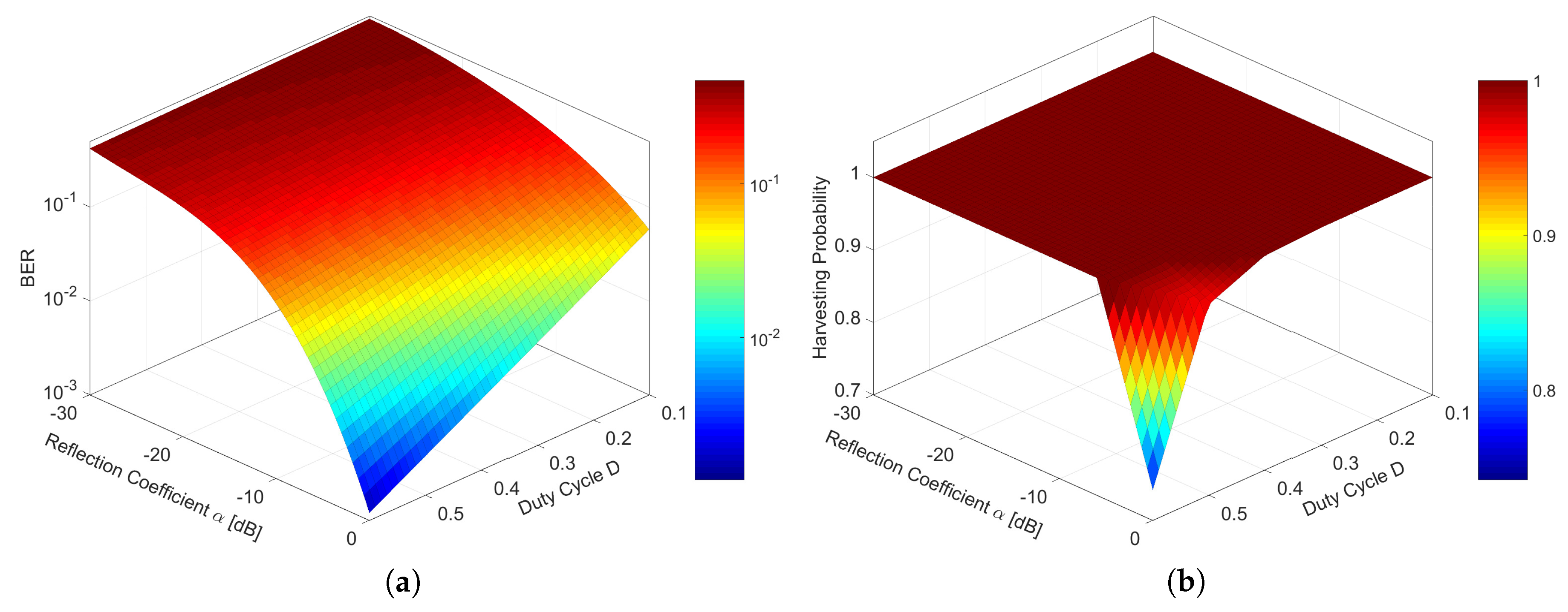
5.4. Simulation 2: Effect of Duty-Cycling Operation

Figure 11 shows the effect of the duty cycle D and the reflection coefficient α on the BER and harvesting probability (or activation probability of RF tags) which is defined by p ( E ) = E [ a n ] for n = 1 , , N . The duty cycle D = K 1 K is controlled by the signal dimension K 1 and related to both the energy harvesting efficiency and data transmissions. The case of D = 0.1 is equivalent to the TD-AmBC system which shows 100% harvesting at tags (i.e., all tags can harvest sufficient energy required for their data transmissions) but exhibits very high BER, thereby limiting the communication range of AmBC. As the duty cycle of tags increases, the BER performance improves since the backscatter signals are conveyed over multiple OFDM carriers, as we confirmed at the previous simulation. However, due to frequent activation of RF circuits, the harvesting probability diminishes for large values of D > 0.5 and α > 5 dB. Fortunately, the energy loss in the duty-cycling operation can be effectively avoided by proper tuning of D and α to satisfy the EH constraint in Equation (21). In addition, to design ’sparse’ codes, a small duty cycle, or equivalently a small K 1 is preferred for low-complexity detection at the reader [23]. Hence, under these settings, the MSC-AmBC demonstrates superior detection performance to the TD-AmBC, while increasing the communication range of AmBC.

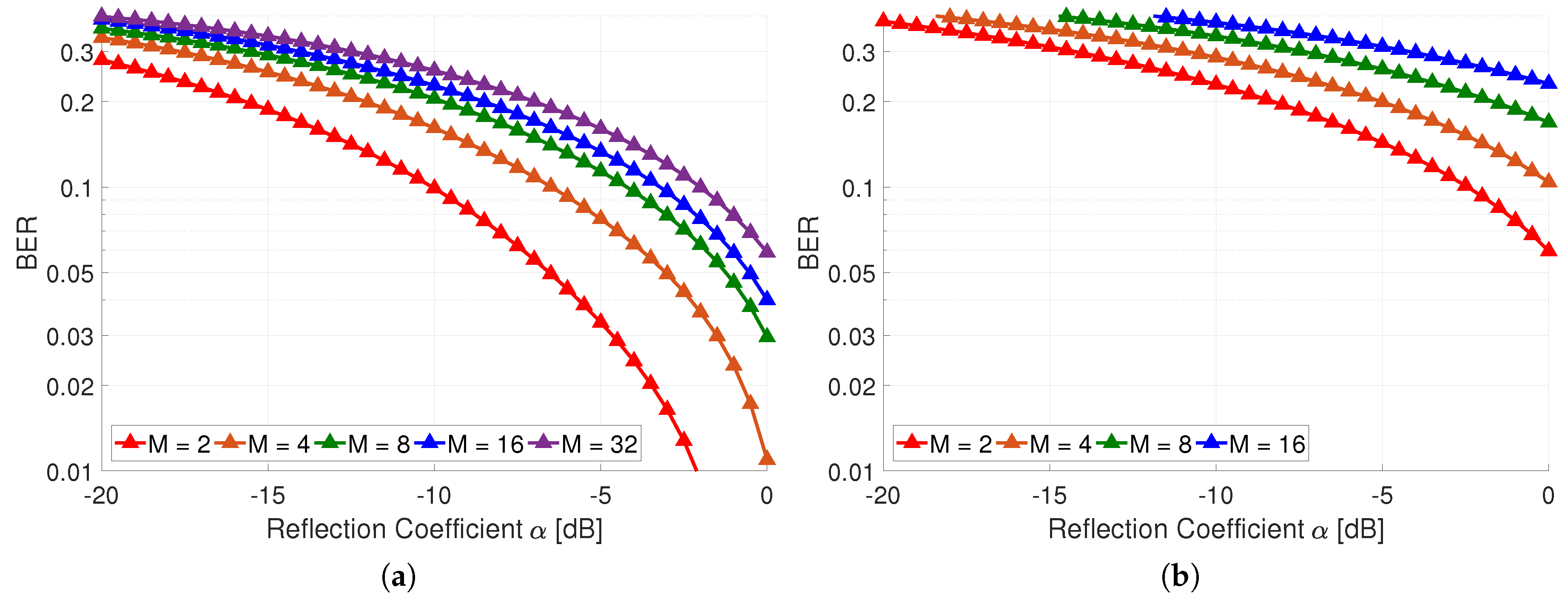
5.5. Simulation 3: Effect of Signal Constellation

Figure 12 shows the comparison of BER in MSC-AmBC and TD-AmBC with respect to the modulation order M and the reflection coefficient α . Based on K 1 = 5 -dimensional signal space, the MSC-AmBC can support M = 2 K 1 = 32 -ary modulation using only M ˜ = 2 load impedances which are very simple to implement at the IoT devices with small form-factor, such as biosensors and wearables. As a result, the high-order modulation with M 32 can be successfully supported in the MSC-AmBC while only 16-ary PSK modulation available at the conventional TD-AmBC due to the hardware limitation of RF tags. Interestingly, formation of the multi-dimensional constellation is helpful not only for practical implementations but also for multiplexing data. For example, 32-ary signal constellation of the MSC-AmBC has the minimum Euclidean distance of d min = 2 α which is equal to that of BPSK modulation of the TD-AmBC. As demonstrated in Figure 12, 32-ary modulation of the MSC-AmBC performs similar to BPSK modulation of the TD-AmBC while multiplexing V = log 2 M = 5 bits per OFDM symbol effectively. Consequently, high-rate and long-range AmBC can be achieved with sparse codes by overcoming both the hardware and channel limitations inherent in AmBC.

5.6. Simulation 4: Effect of Sparse Codes

Figure 13 shows the effect of the overloading factor λ = N K and the reflection coefficient α for the BER. If the codewords of tags are designed in low density as depicted in Figure 6, these codewords can be compressed to efficiently overload multiple data by virtue of their sparsity. When the number of tags is N = 10 , the minimum number of time slots is K = 5 for K 1 = 2 since it satisfies the condition in Equation (17). Hence, λ -fold increase in the data rate can be achieved by compressing K in Equation (47). It is remarkable that although the data rate is improved by increasing the overloading factor, the BER performance is not degraded by the parameter λ . When the codewords are sparsely encoded at tags and the iterative MPA-based decoding at the reader are employed, a higher data rate can be achieved in AmBC without loss of the detection performance. Thus, multi-dimensional signalling in the MSC-AmBC can realize high-rate communication by controlling the overloading factor λ and the modulation order M while long-range communication by controlling the duty cycle D. Potential applications of the proposed MSC-AmBC include smart city and factory where a massive number of low-power IoT devices are concurrenty connected to the Internet to monitor our daily routines.

6. Conclusions

In this paper, we have proposed the MSC-AmBC system based on sparse codes to support long-range and high-rate ambient backscatter communications for massive IoT networks. To design such a system, we utilized the inherent characteristics of ambient sources as well as multiple tags. By utilizing the common OFDM carriers from these sources, we can effectively eliminate the strong DLI with DFT operation and band-pass filtering to extract the useful pilots contained in ambient signals. Also, utilization of the sparsity in batteryless RF tags can increase the dimension of signal space to achieve diversity or multiplexing in AmBC. We have proposed the heuristic algorithm for optimal design of the constellation mapping matrix and the reflection coefficient projection and expansion method in MPA to effectively construct the multi-dimensional constellation essential for high-order backscatter modulation. The proposed modulation can readily be implemented at batteryless IoT devices without increasing hardware costs whose effectiveness was confirmed by numerical evaluations. Therefore, the MSC-AmBC will be a promising solution for massive IoT networks where a huge number of active and passive IoT devices coexist, such as smart city/factory, or LP-WAN.

Author Contributions

T.Y.K. has contributed to the theoretical approaches, simulation and preparing the paper; D.I.K. provides revision.

Funding

This work was funded by the Korean government (MSIT) (NRF-2014R1A5A1011478).

Acknowledgments

This work was supported by the National Research Foundation of Korea (NRF) grant funded by the Korean government (MSIT) (NRF-2014R1A5A1011478).

Conflicts of Interest

The authors declare no conflict of interest.

References

  1. Liu, V.; Parks, A.; Talla, V.; Gollakota, S.; Wetherall, D.; Smith, J.R. Ambient backscatter: Wireless communication out of thin air. In Proceedings of the ACM SIGCOMM’13, Hong Kong, China, 12–16 August 2013; pp. 39–50. [Google Scholar]
  2. Parks, A.N.; Liu, A.; Gollakota, S.; Smith, J.R. Turbocharging ambient backscatter communication. In Proceedings of the ACM SIGCOMM’14, Chicago, IL, USA, 17–22 August 2014; pp. 619–630. [Google Scholar]
  3. Bharadia, D.; Joshi, K.R.; Kotaru, M.; Katti, S. BackFi: High throughput WiFi backscatter. In Proceedings of the ACM SIGCOMM’15, London, UK, 17–21 August 2015; pp. 283–296. [Google Scholar]
  4. Ensworth, J.F.; Reynolds, M.S. Every smart phone is a backscatter reader: Modulated backscatter compatibility with Bluetooth 4.0 low energy (BLE) devices. In Proceedings of the 2015 IEEE International Conference on RFID (IEEE RFID 2015), San Diego, CA,, USA, 15–17 April 2015; pp. 78–85. [Google Scholar]
  5. Kellogg, B.; Parks, A.; Gollakota, S.; Smith, J.R.; Wetherall, D. Wi-Fi backscatter: Internet connectivity for RF-powered devices. In Proceedings of the ACM SIGCOMM’14, Chicago, IL, USA, 17–22 August 2014; pp. 607–618. [Google Scholar]
  6. Griffin, J.D.; Durgin, G.D. Link envelope correlation in the backscatter channel. IEEE Commun. Lett. 2007, 11, 735–737. [Google Scholar] [CrossRef]
  7. Griffin, J.D.; Durgin, G.D. Gains for RF tags using multiple antennas. IEEE Trans. Antennas Propag. 2008, 56, 563–570. [Google Scholar] [CrossRef]
  8. Liu, H.-C.; Lin, W.-C.; Lin, M.-Y.; Hsu, M.-H. Passive UHF RFID tag with backscatter diversity. IEEE Antennas Wirel. Propag. Lett. 2011, 10, 415–418. [Google Scholar]
  9. Wang, J.; Hassanieh, H.; Katabi, D.; Indyk, P. Efficient and reliable low-power backscatter networks. In Proceedings of the ACM SIGCOMM’12, Helsinki, Finland, 13–17 August 2012; pp. 61–72. [Google Scholar]
  10. Liu, W.; Huang, K.; Zhou, X.; Durrani, S. Full-duplex backscatter interference networks based on time-hopping spread spectrum. IEEE Trans. Wirel. Commun. 2017, 16, 4361–4377. [Google Scholar] [CrossRef]
  11. Yang, G.; Zhang, Q.; Liang, Y.-C. Cooperative ambient backscatter communications for green internet-of-things. IEEE Internet Things J. 2018, 5, 1116–1130. [Google Scholar] [CrossRef]
  12. Yang, G.; Liang, Y.-C.; Zhang, R.; Pei, Y. Modulation in the air: Backscatter communication over ambient OFDM carrier. Backscatter communications over ambient OFDM signals: Transceiver design and performance analysis. IEEE Trans. Commun. 2018, 66, 1219–1233. [Google Scholar] [CrossRef]
  13. Guo, J.; Zhou, X.; Durrani, S.; Yanikomeroglu, H. Design of non-orthogonal multiple access enhanced backscatter communication. arXiv, 2018; arXiv:1711.11193. [Google Scholar] [CrossRef]
  14. Talla, V.; Hessar, M.; Kellogg, B.; Najafi, A.; Smith, J.R.; Gollakota, S. LoRa backscatter: Enabling the vision of ubiquitous connectivity. Proc. ACM Interact. Mob. Wearable Ubiquitous Technol. 2017, 1, 105. [Google Scholar] [CrossRef]
  15. Boyer, C.; Roy, S. Space time coding for backscatter RFID. IEEE Trans. Wireless Commun. 2013, 12, 2272–2280. [Google Scholar] [CrossRef]
  16. He, C.; Wang, Z.J.; Miao, C.; Leung, V.C.M. Block-level unitary query: Enabling orthogonal-link space-time code with query diversity for MIMO backscatter RFID. IEEE Trans. Wirel. Commun. 2016, 15, 1937–1949. [Google Scholar] [CrossRef]
  17. Qian, J.; Parks, A.N.; Smith, J.R.; Gao, F.; Jin, S. IoT communications with M-PSK modulated ambient backscatter: Algorithm, analysis, and implementation. IEEE Internet Things J. 2018. [Google Scholar] [CrossRef]
  18. Thomas, S.J.; Wheeler, E.; Teizer, J.; Reynolds, M.S. Quadrature amplitude modulated backscatter in passive and semipassive UHF RFID systems. IEEE Trans. Microw. Theory Tech. 2012, 60, 1175–1182. [Google Scholar] [CrossRef]
  19. Boyer, C.; Roy, S. Coded QAM backscatter modulation for RFID. IEEE Trans. Commun. 2012, 60, 1925–1934. [Google Scholar] [CrossRef]
  20. Thomas, S.J.; Reynolds, M.S. A 96 Mbit/sec, 15.5 pJ/bit 16-QAM modulator for UHF backscatter communication. In Proceedings of the 2012 IEEE International Conference on RFID (IEEE RFID 2012), Orlando, FL, USA, 3–5 April 2012; pp. 185–190. [Google Scholar]
  21. Besnoff, J.; Abbasi, M.; Ricketts, D.S. High data-rate communication in near-field RFID and wireless power using higher order modulation. IEEE Trans. Microw. Theory Tech. 2016, 64, 401–413. [Google Scholar] [CrossRef]
  22. Jordao, M.; Correia, R.; Carvalho, N.B. High order modulation backscatter systems characterization. In Proceedings of the 2018 IEEE Topical Conference on Wireless Sensors and Sensor Networks (WiSNet), Anaheim, CA, USA, 14–17 January 2018; pp. 44–46. [Google Scholar]
  23. Nikopour, H.; Baligh, H. Sparse code multiple access. In Proceedings of the 2013 IEEE 24th International Symposium on Personal Indoor and Mobile Radio Communications (PIMRC Workshops), London, UK, 8–9 September 2013; pp. 332–336. [Google Scholar]
  24. Kim, T.Y.; Kim, D.I. Novel sparse-coded ambient backscatter communication for massive IoT connectivity. arXiv, 2018; arXiv:1806.02975. [Google Scholar] [CrossRef]
  25. Darsena, D.; Gelli, G.; Verde, F. Modeling and performance analysis of wireless networks with ambient backscatter devices. IEEE Trans. Commun. 2017, 65, 1797–1814. [Google Scholar] [CrossRef]
  26. Wu, Y.; Zhang, S.; Chen, Y. Iterative multiuser receiver in sparse code multiple access systems. In Proceedings of the 2015 IEEE International Conference on Communications (ICC), London, UK, 8–12 June 2015; pp. 2918–2923. [Google Scholar]
  27. Bayesteh, A.; Nikopour, H.; Taherzadeh, M.; Baligh, H.; Ma, J. Low complexity techniques for SCMA detection. In Proceedings of the 2015 Globecom Workshops (GC Wkshps), San Diego, CA, USA, 6–10 December 2015. [Google Scholar]
  28. Dai, L.; Wang, B.; Yuan, Y.; Han, S.; Chih-Lin, I.; Wang, Z. Non-orthogonal multiple access for 5G: Solutions, challenges, opportunities, and future research trends. IEEE Commun. Mag. 2015, 53, 74–81. [Google Scholar] [CrossRef]
  29. Cai, Y.; Qin, Z.; Cui, F.; Li, G.Y.; McCann, J.A. Modulation and multiple access for 5G networks. IEEE Commun. Surv. Tutor. 2018, 20, 629–646. [Google Scholar] [CrossRef]
  30. Liu, Y.; Ding, Z.; Elkashlan, M.; Poor, H.V. Cooperative non-orthogonal multiple access with simultaneous wireless information and power transfer. IEEE J. Sel. Areas Commun. 2016, 34, 938–953. [Google Scholar] [CrossRef]
  31. Liu, Y.; Wang, G.; Dou, Z.; Zhong, Z. Coding and detection schemes for ambient backscatter communication systems. IEEE Access 2017, 5, 4947–4953. [Google Scholar] [CrossRef]
  32. Lu, X.; Niyato, D.; Jiang, H.; Kim, D.I.; Xiao, Y.; Han, Z. Ambient backscatter assisted wireless powered communications. IEEE Wirel. Commun. 2018, 35, 170–177. [Google Scholar] [CrossRef]
  33. Cai, X.; Giannakis, G.B. Error probability minimizing pilots for OFDM with M-PSK modulation over Rayleigh-fading channels. IEEE Trans. Veh. Technol. 2004, 53, 146–155. [Google Scholar] [CrossRef]
  34. Wang, Z.; Giannakis, G.B. Wireless multicarrier communications: Where Fourier meets Shannon. IEEE Sig. Process. Mag. 2000, 17, 29–48. [Google Scholar] [CrossRef]
  35. Talla, V.; Smith, J.R. Hybrid analog-digital backscatter: A new approach for battery-free sensing. In Proceedings of the 2013 IEEE International Conference on RFID (IEEE RFID 2013), Penang, Malaysia, 30 April–2 May 2013; pp. 74–81. [Google Scholar]
  36. Taherzadeh, M.; Nikopour, H.; Bayesteh, A.; Baligh, H. SCMA codebook design. In Proceedings of the 2014 IEEE 80th Vehicular Technology Conference (VTC Fall), Vancouver, BC, Canada, 14–17 September 2014. [Google Scholar]
  37. Au, K.; Zhang, L.; Nikopour, H.; Yi, E.; Bayesteh, A.; Vilaipornsawai, U.; Ma, J.; Zhu, P. Uplink contention based SCMA for 5G radio access. In Proceedings of the 2014 Globecom Workshops (GC Wkshps), Austin, TX, USA, 8–12 December 2014; pp. 900–905. [Google Scholar]
  38. Boutros, J.; Viterbo, E. Signal space diversity: A power- and bandwidth-efficient diversity technique for the Rayleigh fading channel. IEEE Trans. Inf. Theory 1998, 44, 1453–1467. [Google Scholar] [CrossRef]
  39. Peng, J.; Chen, W.; Bai, B.; Guo, X.; Sun, C. Joint optimization of constellation with mapping matrix for SCMA codebook design. IEEE Sig. Process. Lett. 2017, 24, 264–268. [Google Scholar] [CrossRef]
  40. Han, K.; Huang, K. Wirelessly powered backscatter communication networks: Modeling, coverage and capacity. IEEE Trans. Wirel. Commun. 2017, 16, 2548–2561. [Google Scholar] [CrossRef]
  41. Kim, Y.-H.; Ahn, H.-S.; Yoon, C.; Lim, Y.; Lim, S.-O. An ambient RF energy harvesting and backscatter modulating tag system enabling zero-power wireless data communication. In Proceedings of the Seventh International Conference on the Internet of Things (IoT ’17), Linz, Austria, 22–25 October 2017. [Google Scholar]
  42. Donoho, D.L. Compressed sensing. IEEE Trans. Inf. Theory 2006, 52, 1289–1306. [Google Scholar] [CrossRef]
  43. Robertson, P.; Villebrun, E.; Hoeher, P. A comparison of optimal and sub-optimal MAP decoding algorithms operating in the log domain. In Proceedings of the 1995 IEEE International Conference on Communications (ICC), Seattle, WA, USA, 18–22 June 1995; pp. 1009–1013. [Google Scholar]
  44. Hoshyar, R.; Wathan, F.P.; Tafazolli, R. Novel low-density signature for synchronous CDMA systems over AWGN channel. IEEE Trans. Sig. Process. 2008, 56, 1616–1626. [Google Scholar] [CrossRef] [Green Version]
  45. ISO/IEC Standard for Information Technology—Telecommunications and Information Exchange between Systems—Local and Metropolitan Area Networks—Specific Requirements Part 11: Wireless LAN Medium Access Control (MAC) and Physical Layer (PHY) Specifications (Includes ISO/IEC 8802-11 IEEE Std 802.11 Second edition 2005-08-01 ISO/IEC 8802 11:2005(E) IEEE Std 802.11i-2003 Edition); IEEE: Piscataway, NJ, USA, 2005; pp. 1–721.
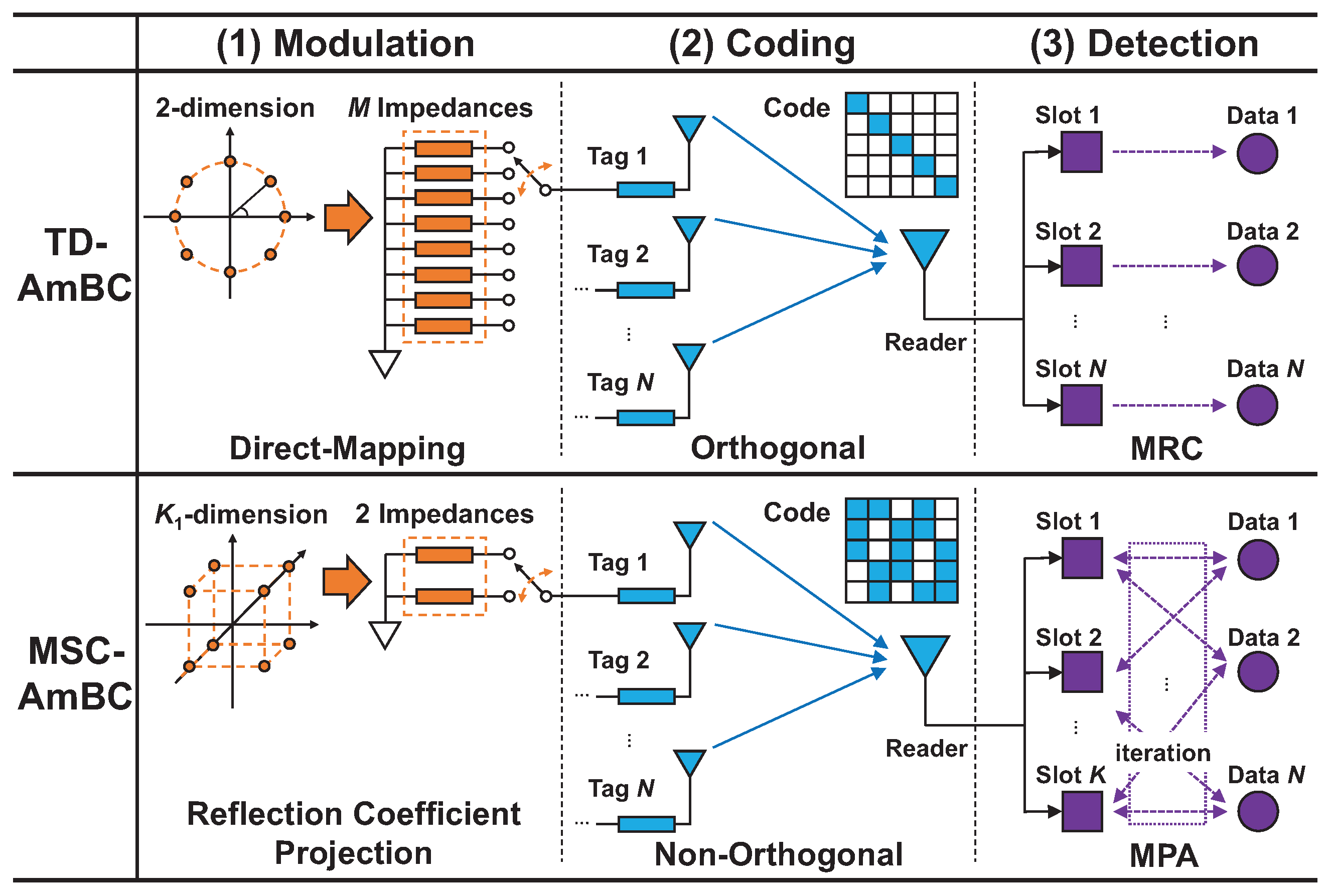
Figure 1. System architecture of MSC-AmBC over multiple OFDM carriers.
Energies 11 02855 g001
Figure 2. General structure of OFDM carrier in frequency domain.
Energies 11 02855 g002
Figure 3. Brief overview of MSC-AmBC modulation at RF tags.
Energies 11 02855 g003
Figure 4. Comparision of symbol mapping for M = 4 and K 1 = 2 . (a) M ˜ = 3 projection points; (b) M ˜ = 2 projection points.
Energies 11 02855 g004
Figure 5. Example of the constellation mapping function with respect to M and K 1 for M ˜ = 2 . ( b = [ 1 , 1 ] T ).
Energies 11 02855 g005
Figure 6. Example of the factor graph design when N = 10 .
Energies 11 02855 g006
Figure 7. Brief overview of MSC-AmBC detection at the reader.
Energies 11 02855 g007
Figure 8. Block diagram of AmBC systems in view of modulation, coding and detection.
Energies 11 02855 g008
Figure 9. Simulation settings for the MSC-AmBC system. (a) Deployment scenario with U = 10 sources, N = 10 tags, and a reader located at the origin. (b) Common system parameters [3,18,25,41,45].
Energies 11 02855 g009
Figure 10. Effect of the pilot power ratio ζ and the reflection coefficient α for detection performance at the reader. (If ζ 0.08 , equal power is allocated among data and pilot subcarriers). (a) BER performance in MSC-AmBC ( K = 10 , K 1 = 3 , M = 2 ). (b) BER performance in TD-AmBC ( K = 10 , K 1 = 1 , M = 2 ).
Energies 11 02855 g010
Figure 11. Effect of the duty cycle D and the reflection coefficient α for detection and energy harvesting performances ( D = 0.1 represents the TD-AmBC system). (a) BER performance in MSC-AmBC ( K = 10 , ζ = 0.16 , M = 2 ). (b) Harvesting probability in MSC-AmBC ( K = 10 , ζ = 0.16 , M = 2 ).
Energies 11 02855 g011
Figure 12. Effect of the modulation order M and the reflection coefficient α for detection and energy harvesting performances (MSC-AmBC: modulation with iterative projections and expansions using M ˜ = 2 impedances, TD-AmBC: M-PSK modulation using M ˜ = 16 impedances). (a) BER performance in MSC-AmBC ( K = 10 , ζ = 0.16 , D = 0.5 ). (b) BER performance in TD-AmBC ( K = 10 , ζ = 0.16 , D = 0.1 ).
Energies 11 02855 g012
Figure 13. Effect of the overloading factor λ and the reflection coefficient α for detection performance at the reader when ζ = 0.16 , D = 0.2 , and M = 2 .
Energies 11 02855 g013
Table 1. Comparison of AmBC systems evaluated in numerical simulations.
ComponentTD-AmBCMSC-AmBC
(1) Modulation[3,17,18,19,20,21,22]
      Signal constellation2-dimensional PSK/QAM K 1 2 dimensional lattice
      Load impedance M 2 impedances M ˜ = 2 impedances only ( M ˜ M )
      Symbol mappingdirect-mapping (M-to-M)reflection coefficient projection (M-to- M ˜ )
(2) Coding[3,10,32]
      Multiple accessOMA using TDMANOMA using sparse code
      Duty cyclelimited to D 1 N extended to D K 1 K where K N , K 1 2
      Codewordorthogonal (or diagonal)non-orthogonal and interfering codes
(3) Detection[3,11,25]
      Diversity combiningN parallel MRC blocksintegrated MPA with K ˜ FNs and N VNs
      ML detectionhypothesis test in 2 dimensionprojection & expansion in K 1 dimension

