Article

Constant-Frequency Model Predictive Direct Power Control for Fault-Tolerant Bidirectional Voltage-Source Converter with Balanced Capacitor Voltage

1
College of Electrical and Information Engineering, Hunan University, Changsha 410082, China
2
College of Electrical Engineering and Information Engineering, Hunan Institute of Engineering, Xiangtan 411104, China
3
College of Electrical and Information Engineering, Zhengzhou University of Light Industry, Zhengzhou 450002, China
*
Author to whom correspondence should be addressed.
Energies 2018, 11(10), 2692; https://doi.org/10.3390/en11102692
Submission received: 20 September 2018 / Revised: 30 September 2018 / Accepted: 30 September 2018 / Published: 10 October 2018
(This article belongs to the Section I: Energy Fundamentals and Conversion)

Abstract

:
This paper proposes a constant-frequency model predictive direct power control (CF-MPDPC) method for a fault-tolerant bidirectional voltage-source converter (BVSC). The method can enhance the reliability and fault-tolerant operation capability of BVSCs in the condition of bridge-arm fault. Through the analysis of a fault-tolerant three-phase four-switch (TPFS) structure and the voltage vectors in the αβ stationary frame, the predictive power model and DC-link midpoint voltage offset suppression are established. According to model-predictive theory, fault-tolerant TPFS, and multivector control, the CF-MPDPC method for fault-tolerant BVSC is presented. The method realizes direct power control based on three output vectors with constant frequency, which can track the optimal vector more accurately and reduce current harmonics. Furthermore, the balanced control of DC-link capacitor voltages is also achieved by adding the term of DC-link midpoint voltage offset into the cost function. The balanced capacitor voltages protect the converter against the second faults caused by over-voltage operation of electrolytic capacitor. The simulation and experimental results prove that the fault-tolerant BVSC controlled by proposed method can maintain the continuous operation when the switching devices have fault. Low current harmonic content and stable output power exhibit good reliability and dynamic performance of the proposed CF-MPDPC for a fault-tolerant BVSC with a phase fault.

1. Introduction

Due to environment pollution and fossil-energy reduction, clean energy such as solar and wind energy have quickly been promoted in many developed and developing countries. As the key equipment of grid integration of renewable-energy generation, the bidirectional voltage-source converter (BVSC) can realize AC/DC bidirectional power conversion with high efficiency [1,2,3,4,5]. Furthermore, many other energy conversion examples, such as distributed generation and electric vehicles, also depend on the reliable operation of BVSC. However, due to surges and spikes caused by high voltage, the switching devices of BVSC are prone to have faults, which leads to discontinuous operation and degrades power quality. Therefore, it’s necessary and significant to research the fault-tolerant BVSC and improve reliability in a condition of switching device faults.
When the switching devices of the traditional three-phase six-switch (TPSS) converter have an open-circuit fault, the faulty phase is usually connected to the midpoint of DC-link capacitors to form a three-phase four-switch (TPFS) fault-tolerant structure to keep working. Since the topology structure is changed, the control method should be adjusted for a TPFS fault-tolerant structure [6,7,8,9,10,11,12]. For TPFS shunt active power filters, a three-level hysteresis current-control (HCC) strategy is proposed to enables access to the zero level of the input voltage to reduce switching frequency. Furthermore, the imbalance of capacitor voltages is eliminated by adding a feedback term to the current control [6]. Due to the fact that a TPFS converter usually operates at half the DC input voltage, TPFS topology based on single-ended primary-inductance converter (SEPIC) is proposed to improve the utilization factor of the input DC supply, and integral sliding-mode control is used to optimize dynamic performance [7]. Three space-vector pulse-width modulation methods using different equivalent zero vectors are proposed for the TPFS pulse width modulation (PWM) rectifier to reduce current ripples. Furthermore, the control-oriented model is built to eliminate capacitor voltage deviation [12]. TPFS topology is also used in the motor drive for cost-effective low-power applications. For an induction motor (IM) driven by TPFS inverter, a fuzzy-logic controller (FLC) is proposed with more robust and better dynamic responses than the traditional proportional-integral (PI) controller [10]. The fault-tolerant operation against DC faults for a multiterminal high-voltage direct current (HVDC) transmission system was also studied by researchers. Due to that the DC fault of a modular multilevel converter (MMC) constrains its application in HVDC transmission systems, a new hybrid-cascaded MMC is proposed to improve its DC fault ride-through capability. The main power stage based on a half-bridge cell generates the fundamental voltages, while the cascade full-bridge (FB) cells attenuate the harmonics [13]. In order to deal with the DC line faults, a new protection scheme consisting of a main protection and a backup protection is presented for multiterminal HVDC based on VSCs [14]. Since the VSCs are vulnerable against DC-side faults, three different configurations of solid-state DC circuit breakers (CB) for protection purposes and a new control method to interrupt the DC fault current for multiterminal HVDC are studied to protect the VSCs [15]. The TPFS fault-tolerant control method based on space-vector pulse width modulation requires complex coordinating transformation, a phase-locked loop (PLL), and a PI controller, which is influenced by personal experience. In addition, bidirectional power conversion for TPFS fault-tolerant control needs further study.
Recently, the model predictive control (MPC) has drawn researchers’ attention due to its advantages of simplicity and flexibility. Through a flexible cost function composed by different control targets, the MPC can realize multiobjective control with good dynamic performance and robustness [16,17,18,19,20,21,22,23,24,25]. To reduce the common-mode voltage of three-phase voltage source inverters, MPC is used with only nonzero voltage vectors to track the reference current. Without using zero vectors, the method can reduce common-mode voltage as well as control the load currents with satisfactory performance [18]. The MPC framework is adopted to realize seamless transition between islanded and grid-connected operations for distributed-generation (DG) systems [19]; a hierarchical and decentralized model predictive control scheme is proposed for the HVDC system to quickly track active and reactive power references. Multiple targets, such as improving power quality, providing voltage support, and stabilizing the grid, can be achieved [21]. To achieve robustness against uncertain parameters and simplify the predictive model, the MPC based on a disturbance observer (DOB) is proposed for three-phase inverters with an LC filter [23]. The MPC method is also applied in offshore wind farms and flywheel energy-storage systems. An enhanced voltage-control strategy (EVCS) based on MPC is proposed for offshore wind farms to keep voltages within feasible range and reduce system power losses [24]. An optimal nonlinear controller based on MPC is proposed for flywheel energy-storage systems to control the systems in the presence of uncertainties [25]. Many researchers apply MPC to TPSS converters without considering faulty conditions. In fact, when the switching devices have a fault, the conventional MPC should be modified and further researched to adapt to the fault-tolerant TPFS topology.
Due to the limited voltage vectors of BVSC, conventional MPC selects only one voltage vector that minimize cost function at the next sampling period, which fails to reduce power ripples and current harmonics to minimal values [26,27,28,29,30,31,32,33,34,35]. Recently, MPC with duty-cycle control has been used to further lower power ripples for PWM rectifiers. During the control period, a nonzero vector and a zero vector are applied based on their duration time to minimize power errors [27]. To reduce computational requirements in duty-cycle calculation, the negative conjugate of complex power is chosen as control target based on the double-vector approach [29]. To improve the steady-state performance of induction motor drives, a generalized two-vector-based model-predictive torque control is put forward with two arbitrary voltage vectors [32]. The extended switching vectors and time-optimized control are used in MPC with more freedoms and precise tracking possibility for active front-end power converters to reduce ripples [34]. In order to obtain optimal duty cycles, the cost function based on the desired control performance is adopted for three-phase active-front-end rectifiers [35]. However, the MPC-optimized control is usually applied in normal-operation converters, which ignores the occurrence of switching device faults. In addition, the bidirectional power-conversion control of BVSC and seamless transition between inverter and rectifier mode still need more research.
Traditional MPC selects only one vector in a sampling period, which leads to variable switching frequency and power ripples. Considering the fault of switching devices, the fault-tolerant operation and voltage vectors of TPFS topology are analyzed. This paper proposes a constant-frequency model predictive direct power control (CF-MPDPC) for fault-tolerant BVSC based on three vectors with a fixed operation sequence in each sector. There are two nonzero vectors of a sector and a synthetic zero vector for applying in one sampling period. To reduce the calculation burden, the synthesizing vector is obtained by the three vectors with their durations before bringing them into the final cost function. Due to the unbalanced midpoint of capacitor voltage for TPFS converters, the DC-link voltage offset is analyzed and added into the cost function to make the voltages of the two capacitors equal, which avoids second faults with electrolytic capacitors for overvoltage operations. In consideration of digital implementation and application delay, two-step prediction is adopted in CF-MPDPC for delay compensation. The simulation and experiments with the proposed method are presented and compared with the conventional MPDPC for TPSS converter and MPDPC for fault-tolerant TPFS converter. The results show the effectiveness and superiority of the proposed CF-MPDPC method, with lower current harmonics and smaller power ripples in both inverter and rectifier modes. Furthermore, the seamless transition of the two modes and DC-link voltage offset suppression are verified by the simulation and experiments.

2. Model of Fault-Tolerant BVSC

2.1. Fault-Tolerant Operation Analysis

The reliability of switching devices has serious influence on the normal operation of a BVSC. Due to surges and spikes caused by high voltage and high switching-frequency transition, switching devices tend to have faults. As shown in Figure 1a, there are fast-fuse devices (F1–F6) for every switching device (S1–S6) and bidirectional switches for each phase. When a switching device has a fault, the corresponding fuse device is disconnected and the bidirectional switch of the fault phase is closed to the central point of the two series capacitors in parallel with the DC power; then, the TPFS structure is formed, as shown in Figure 1b, with a Phase A leg fault.
The fault-tolerant structure of BVSC is shown in Figure 1a. When the switching device of Phase A has a fault, the corresponding switch is closed and Phase A is connected to the central point of the DC-link capacitors, which are reconstructed into a TPFS structure, as shown in Figure 1b. Then, four switching devices are left, and the switching states are defined as Si (i = b, c):
S i = { 1 0 upper   bridge   of   i   phase   is   on   and   lower   bridge   is   off upper   bridge   of   i   phase   is   off   and   lower   bridge   is   on
The relationship between ubN, ucN and switching states is:
{ u b N = S b v c 1 + ( S b 1 ) v c 2 u b N = S c v c 1 + ( S c 1 ) v d c 2
Then, output voltages be expressed by switching states as:
{ u a n = v c 1 3 ( S b S c ) + v c 2 3 ( 2 S b S c ) u b n = v c 1 3 ( 2 S b S c ) + v c 2 3 ( 2 S b S c 1 ) u c n = v c 1 3 ( 2 S c S b ) + v c 2 3 ( 2 S c S b 1 )
where vc1 and vc2 are voltages of capacitor C1 and C2, respectively.
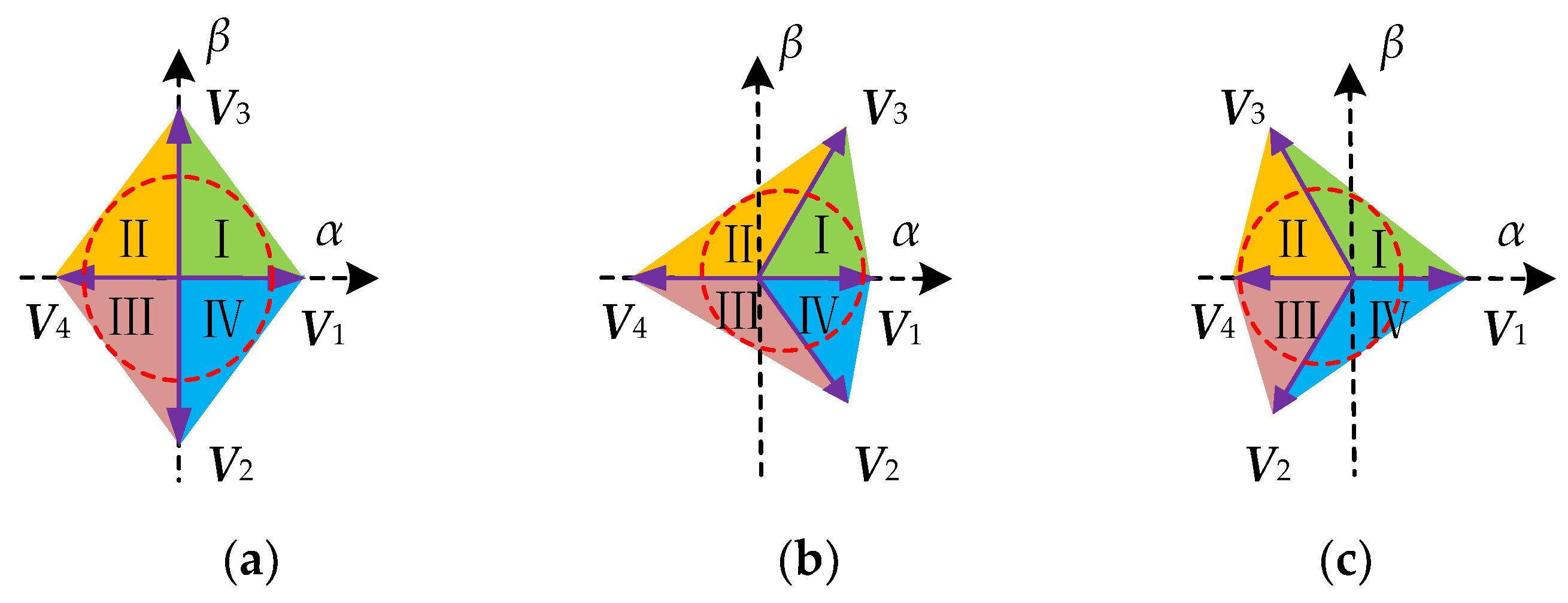
Then, the output voltage in the αβ stationary frame when Phase A has a fault under four switching states is obtained in Table 1, and the corresponding graphs of voltage vectors are shown in Figure 2 under the conditions of vc1 = vc2, vc1 < vc2 and vc1 > vc2.

2.2. Predictive Power Model

From the fault-tolerant structure of BVSC in Figure 1, according to the Kirchhoff law, the following state equation in an abc coordinate frame can be obtained [36,37]:
L d d t [ i a i b i c ] + R [ i a i b i c ] = [ u a n e a u b n e b u c n e c ]
where L and R are the filter inductor and line resistance, respectively; ia, ib and ic are currents of Phase A, B, C; uan, ubn and ucn are output voltages of the fault-tolerant BVSC; and ea, eb, and ec are grid voltages.
The relationship between output voltages of a TPFS converter and switching states is:
[ u a n u b n u c n ] = v d c 3 [ 2 1 1 1 2 1 1 1 2 ] [ 1 / 2   S b   S c ]  
After Clark coordinate transformation, Equations (4) and (5) can be converted to the αβ stationary frame as:
L d d t [ i α i β ] + R [ i α i β ] = [ e α e β ] [ u α u β ]  
Then, the predictive currents of BVSC at tk+1 instant can be obtained by discretizing Equation (6):
[ i α ( k + 1 ) i β ( k + 1 ) ] = T s L [ u α ( k ) e α ( k ) u β ( k ) e β ( k ) ] + ( 1 R T s L ) [ i α ( k ) i β ( k ) ]
where TS is the sampling period; iα(k+1), iβ(k+1) are predictive currents at tk+1 instant; uα(k), uβ(k), iα(k), iβ(k), eα(k), eβ(k) are the actual sampling output voltages, currents, and grid voltages in the αβ stationary frame at the tk instant.
According to instantaneous power theory, the predictive power model at the tk+1 instant is then shown as the following:
[ P ( k + 1 ) Q ( k + 1 ) ] = 3 T S 2 L [ e α ( k ) e β ( k ) e β ( k ) e α ( k ) ] [ u α ( k ) e α ( k ) R i α ( k ) u β ( k ) e β ( k ) R i β ( k ) ] + [ P ( k ) Q ( k ) ]
where P(k) and Q(k) are the active power and reactive power at the tk instant, respectively, and P(k+1) and Q(k+1) are the active power and reactive power at the next instant.

2.3. DC-Link Midpoint Voltage-Offset Suppression

When switching devices have a fault, the fault phase is connected to the center point of two series capacitors to form a TPFS structure. However, the voltages of the two capacitors are not equal, which leads to DC-link voltage offset and current harmonics. If the capacitor voltage is over-rated in value, the life of the capacitor would decrease and a secondary BVSC failure would be generated. Therefore, it’s necessary to restrain the DC-link midpoint voltage offset. As shown in Figure 1b, the relationship of two capacitor currents with a Phase A fault can be expressed as follows:
{ C d v c 1 d t = i c 1 C d v c 2 d t = i c 2  
The relationship between the capacitor current and switching states is:
{ i c 1 = i d c i b S b i c S c i c 2 = i d c + i b ( 1 S b ) + i c ( 1 S c )
The voltage offset between two capacitors is obtained as:
C d Δ v d c d t = C d ( v c 1 v c 2 ) d t = i c 1 i c 2 = i a
Then, the difference of two capacitor voltages can be expressed as:
Δ v d c = 1 C k k + 1 i a + ( v c 1 ( k ) v c 2 ( k ) )
After discretizing Equation (12), the predictive DC voltage-offset model at the tk+1 instant is shown as:
Δ v d c ( k + 1 ) = Δ v d c ( k ) + T S C i a ( k )
where TS and C are the sampling period and capacitor value, respectively, and Δvdc(k) is the sampling DC voltage offset at the tk instant. In order to achieve DC-link voltage-offset suppression, the predictive DC voltage offset should be added to the MPC cost function to be minimum.

3. Control Method for a Fault-Tolerant BVSC

3.1. Theoretical Analysis of the Constant-Frequency MPC (CF-MPC) Method

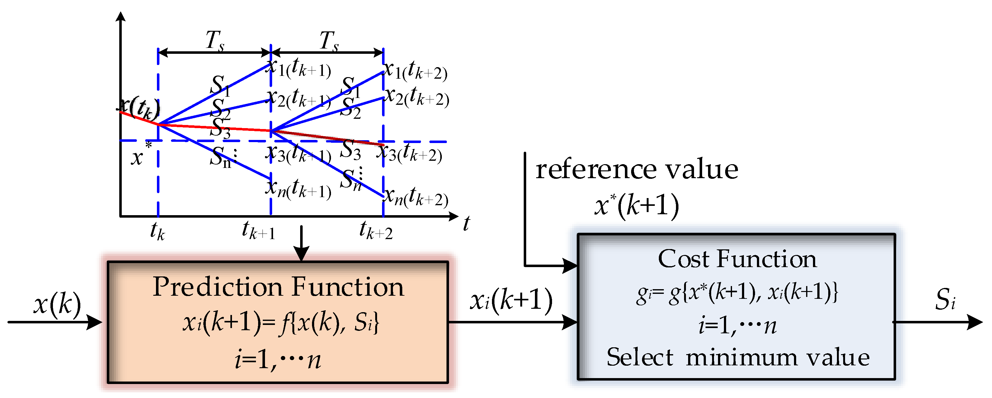
MPC has been used in the control of power electronics as a moving optimization strategy, which has the advantage of convenient modeling and good robust characteristics. The main target is keeping the output value close to reference value x*. As shown in Figure 3, the predictive value at the tk+1 instant is obtained according to sampling value x(tk) and various switching states (S1Sn). Then, cost function is used to compare the predictive value and the reference. Finally, the switching state minimizing the cost function is applied as the optimal choice at next moment. Therefore, the S3 state is used at the tk+1 instant and (Figure 3) since predictive value x3(tk+1) is closest to reference value x*. However, the traditional MPC for a BVSC is applicable in normal operation conditions, which is not considering fault-tolerant operations. Only one voltage vector is applied during a sampling period, which can not track the optimal vector, and it leads to errors between the reference and output values. Since the switching order of the voltage vector at each sampling time is not certain, the switching frequency of power devices is unfixed, which causes unfixed harmonic frequency of the current. Therefore, it’s hard to design a proper filter to eliminate current harmonics.
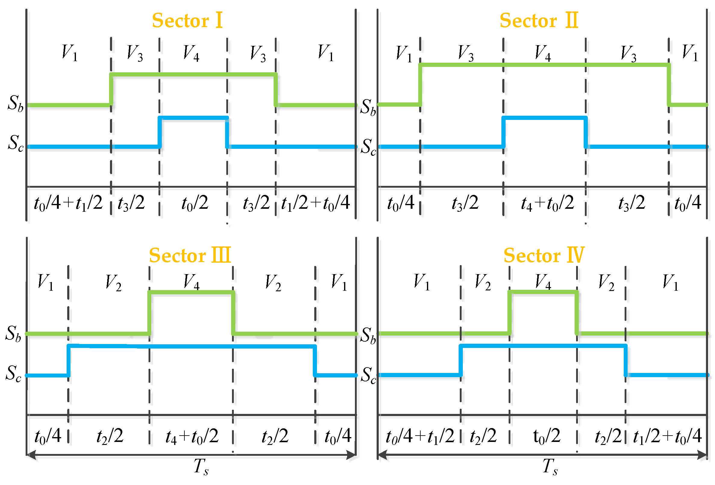
In this paper, CF-MPC is proposed for fault-tolerant BVSC with three voltage vectors in a sampling period to form a fixed switching frequency. The method can improve predictive accuracy closer to the optimal vector and make the current harmonic center on a high frequency, which is easier to be filtered and helpful for filter designing. As shown in Figure 2, the four voltage sectors are formed by voltage vectors V1(0, 0), V2(0, 1), V3(1, 0), V4(1, 1) of a fault-tolerant BVSC with a Phase A fault. In order to minimize output errors, there are three voltage vectors (two nonzero vectors and one synthetic zero vector) adopted in one sampling period to track the optimal vector, which makes up for the shortage of one vector and reduces the predictive error. In addition to two adjacent nonzero vectors in each sector, one zero vector is synthesized by V1 and V4 (each vector lasts over t0/2 time) to improve prediction accuracy. As shown in Figure 4, the duration and sequence diagram of voltage vectors under each sector are various. The vectors are allocated symmetrically and the signal pulses of switching devices are produced by triangular carrier comparison with duty control. In Sector I and II, the vector-composition sequence is V1(0, 0)-V3(1, 0)-V4(1, 1)-V3(1, 0)-V1(0, 0), while in Sector III and IV the vector sequence is V1(0, 0)-V2(0, 1)-V4(1, 1)-V2(0, 1)-V1(0, 0). By this working mode, the simultaneous motion of multiple switching devices is avoided to decrease power loss. The arranged vector sequence generates high frequency of current harmonics, which is favorable for filter design. The upper and lower lines show the switching state of phase B and C, respectively, in one sampling period, which is divided into three parts in Figure 4. The horizontal axis represents the duration for three vectors. Take Sector I for example: t1 and t3 represent the duration of two nonzero vectors V1 and V3, while t0 shows the operation time of the synthetic zero vector (V1 and V4).

3.2. CF-MPC Method for Fault-Tolerant BVSC

To determine the operation time of three vectors in a sampling time, the subcost function for each vector should be calculated to measure the error of one vector. For example, if Phase A has a fault and the voltage vector is in Sector I, the subcost functions under two nonzero vectors (V1, V3) and one zero vector (synthesized by V1 and V4) can be expressed as follows:
{ g 1 = | P r e f P 1 ( k + 1 ) | + | Q r e f Q 1 ( k + 1 ) | g 3 = | P r e f P 3 ( k + 1 ) | + | Q r e f Q 3 ( k + 1 ) | g 0 = | P r e f P 0 ( k + 1 ) | + | Q r e f Q 0 ( k + 1 ) |
where g1, g3, and g0 are the subcost function of three vectors; Pref and Qref are reference active and reactive power; P1(k+1), P3(k+1), P0(k+1), Q1(k+1), Q3(k+1), Q0(k+1) are predictive active powerand reactive power of three vectors at the tk+1 instant by Equation (16).
The subcost function in Equation (14) shows the predictive error under each vector. The evaluation criterion is that the smaller the cost function is, the better the predictive effect is. Therefore, the last vector time with a smaller cost function should be longer. To achieve this working mode, the inverse ratio of a subcost function is used as the operation time of three vectors:
{ t 1 = T s ( 1 g 1 ) / ( ( 1 g 1 ) + ( 1 g 3 ) + ( 1 g 0 ) ) t 3 = T s ( 1 g 3 ) / ( ( 1 g 1 ) + ( 1 g 3 ) + ( 1 g 0 ) ) t 0 = T s ( 1 g 0 ) / ( ( 1 g 1 ) + ( 1 g 3 ) + ( 1 g 0 ) )
where TS is the sampling period; t1, t3, and t0 are the operation time of three vectors.
According to the duration and operation sequence diagram of Sector I in Figure 4, the corresponding duty cycles for switching states Sb and Sc are:
{ d b = t 3 T s + t 0 / 2 T s d c = t 0 / 2 T s
After obtaining the duration of each vector, the voltage in the αβ stationary frame of the synthesizing vector is shown as:
{ u α = ( u α 1 * t 1 + u α 3 * t 3 + u α 0 * t 0 ) / T s u β = ( u β 1 * t 1 + u β 3 * t 3 + u β 0 * t 0 ) / T s
where uα and uβ are the αβ components of synthesizing vector; uα1, uβ1, uα3, uβ3, uα0, and uβ0 are αβ components of three applied vectors.
Substituting Equation (17) to the predictive power model Equation (8), the predictive power of the synthesizing vector at the tk+1 instant is obtained as P(k+1), Q(k+1). Cost function is used to evaluate the predictive values based on control targets. To achieve direct power control, the absolute values between predictive power and reference power are used as power control terms in the cost function. Furthermore, considering the unbalance of DC-side midpoint voltage, the absolute value of predictive DC voltage offset is adopted as a DC capacitor voltage control term in the cost function. In addition, in consideration of digital implementation and application delay, two-step delay prediction is usually adopted in MPC. Therefore, cost function can be expressed as:
g = | P r e f P ( k + 2 ) | + | Q r e f Q ( k + 2 ) | + λ | Δ v d c ( k + 2 ) |
where λ is the weighting coefficient to regulate the DC midpoint voltage, the first two terms are used to control active and reactive power, the last term is to balance DC-side midpoint voltage, P(k+2) and Q(k+2) are predictive active power and reactive power, respectively, at the tk+2 instant, and Δvdc(k+2) is DC voltage offset at the tk+2 instant, which can be obtained by following equations:
[ P ( k + 2 ) Q ( k + 2 ) ] = 3 T 2 L [ e α ( k + 1 ) e β ( k + 1 ) e β ( k + 1 ) e α ( k + 1 ) ] [ u α ( k + 1 ) e α ( k + 1 ) R i α ( k + 1 ) u β ( k + 1 ) e β ( k + 1 ) R i β ( k + 1 ) ] + [ P ( k + 1 ) Q ( k + 1 ) ]
Δ v d c ( k + 2 ) = Δ v d c ( k + 1 ) + T s C i a ( k + 1 )
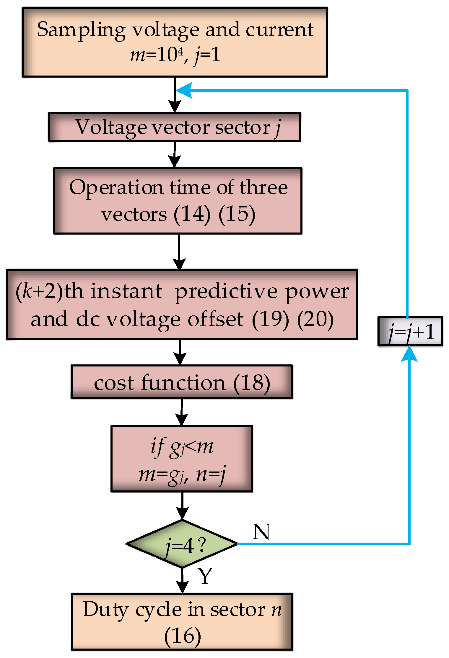
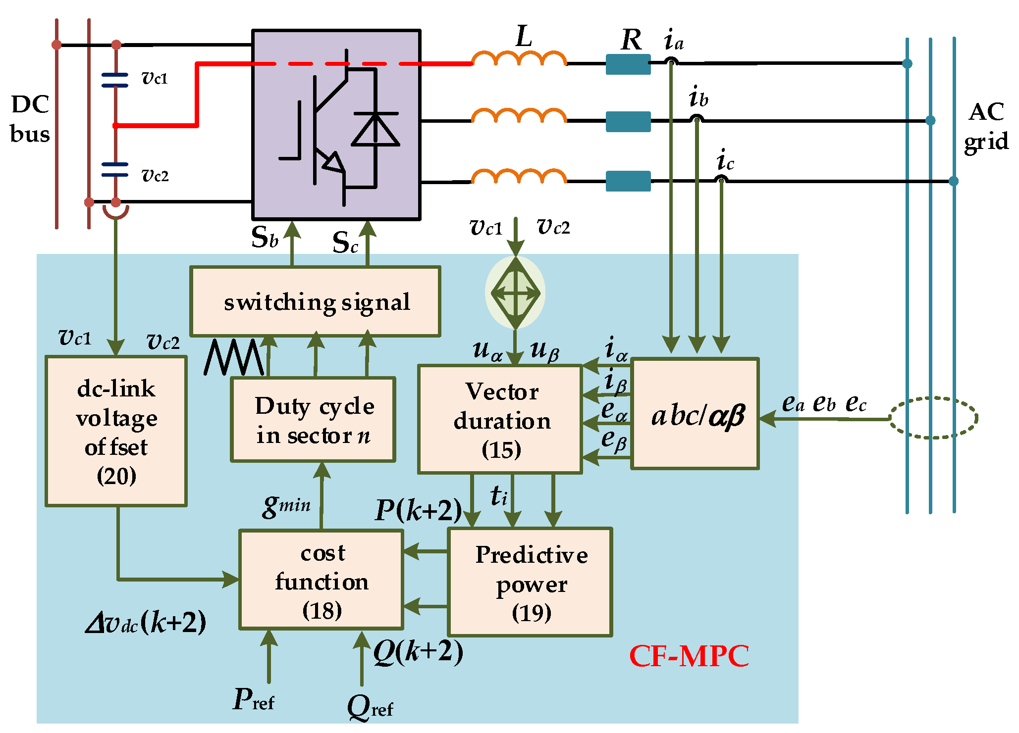
Based on the above CF-MPC predictive model, the flow diagram to select the optimal vector and the control structure for a fault-tolerant BVSC is shown in Figure 5 and Figure 6, respectively. First, the voltage of two capacitors, grid voltage and current, is sampled to prepare for calculating predictive power and DC-link midpoint voltage offset. In order to confirm the optimal vector sector, the four sectors should be tested in turn. Then, the operation time of three vectors in each sector is calculated according to Equations (14) and (15) before ensuring the synthesizing vector. After that, the predictive values at the tk+2 instant are obtained with Equations (19) and (20) and substituted into final cost Equation (18). Lastly, the sector that can minimize cost function is applied and the corresponding three vectors are executed according to their operation time.
Conventional MPC only outputs one uncertain vector in a sampling period, which leads to unfixed frequency and power ripples. The proposed CF-MPDPC generates three vectors based on the selected sector to form fixed switching frequency, which lower the power ripples and reduce current harmonics. The two adjacent vectors and one synthetic zero vector in each sector are used to track the optimal vector. To determine the duration of three vectors in a sampling time, the sub-cost function of each vector is calculated to measure the error and then the duration is the inverse ratio of sub-cost function. Based on the duration of vectors, the corresponding duty cycles for switching states and the synthesizing vector for three vectors can be obtained. According to the synthesizing vector and predictive model, the cost function is calculated to evaluate the predictive values. The sector which minimizes the cost function is the selected sector and the corresponding duty cycle is applied at next sampling time.

4. Simulation and Experiment Results

4.1. Simulation Results for Fault-Tolerant BVSC

The simulation models are built by modules in MATLAB Simulink 2014b (The MathWorks, Inc, Natick, MA, USA) with the parameters shown in Table 2. To verify the effectiveness and superiority of proposed method, three control methods (MPDPC for TPSS converter, MPDPC for TPFS fault-tolerant BVSC and proposed CF-MPDPC for TPFS fault-tolerant BVSC) are simulated under the same condition for comparison. The steady state simulations of fault-tolerant BVSC with switch open-circuit fault of Phase A occurred in inverter mode and rectifier mode are implemented. Besides, the dynamic simulation and balanced capacitor voltages are achieved to further validate the feasibility and advantage of proposed method.
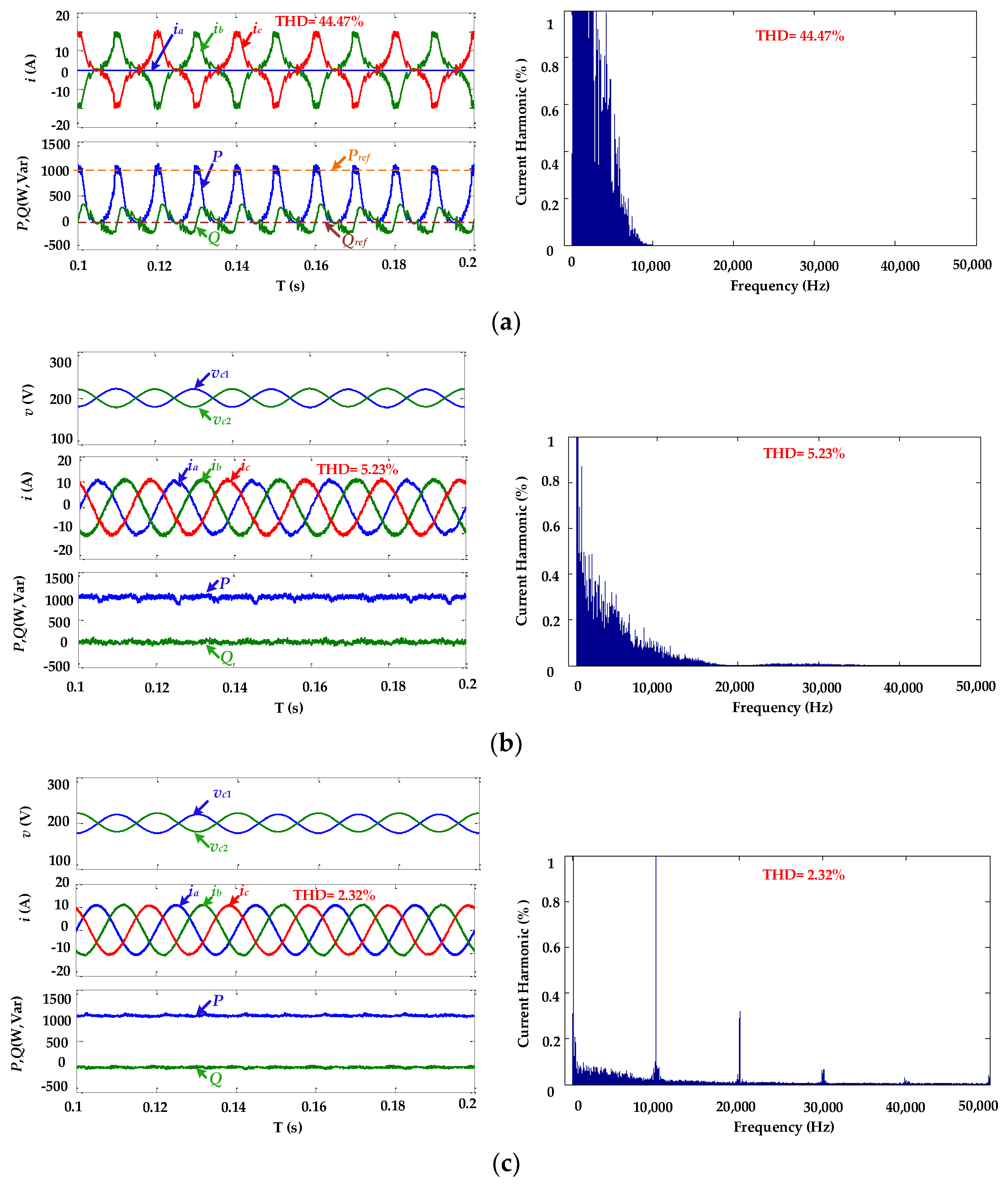
Figure 7 shows the simulation results for BVSC with a Phase A fault in inverter mode. The reference active power and reactive power are 1000 W and 0 Var, respectively. To compare output power and current for a TPFS fault-tolerant control, the DC-link voltage offset is added to the cost function for both the MPDPC and proposed CF-MPDPC methods. The weighting coefficient of DC-link voltage offset λ is 1000, which is determined by multiple tests. The total harmonic distortion (THD) of a current under the traditional MPDPC for TPSS was 44.47%, and output power fluctuated wildly, as shown in Figure 7a. The reason is that traditional MPDPC based on six vectors for BVSC don’t take fault-tolerant operations into account. Therefore, once the phase fault occurs, Phase A is disconnected and output vectors change with the fault phase. The current of the fault phase is zero, which leads to an unsustainable operation. The output current and power under MPDPC for a fault-tolerant BVSC is much improved, as shown in Figure 7b, with balanced capacitor voltage. The THD of the current was 5.23%, and output power remained basically stable with small ripples. That’s because the fault-tolerant BVSC can link the fault phase to the center point of DC-side capacitors and the MPDPC is operated under four vectors, which keep the BVSC controllable with phase faults. DC-link voltage is restricted to balance due to the DC-link voltage-offset term in cost function. When the cost function is minimum, voltage difference between two capacitors is minimized. However, since only one uncertain vector is adopted in one sampling time, the MPDPC method can’t precisely track the optimal output vector, and the unfixed switching frequency leads to various low-frequency harmonics. The current THD is 2.32% under the control of the proposed CF-MPDPC, as shown in Figure 7c, which decreases 2.91% compared to MPDPC for a fault-tolerant BVSC. The output power of the converter is smoother with lower ripples, which is better than the other two methods. The voltages of the two capacitors are balanced due to the restriction of the DC-link voltage offset. Since there were three vectors executed according to their operation times, the actual output vector was closer to the optimal vector, which forms better and smoother output power. The fixed switching frequency makes the current harmonics center on high frequency, which can be more easily filtered. Therefore, the steady performance of fault-tolerant BVSC controlled by proposed CF-MPDPC are improved in inverter mode.
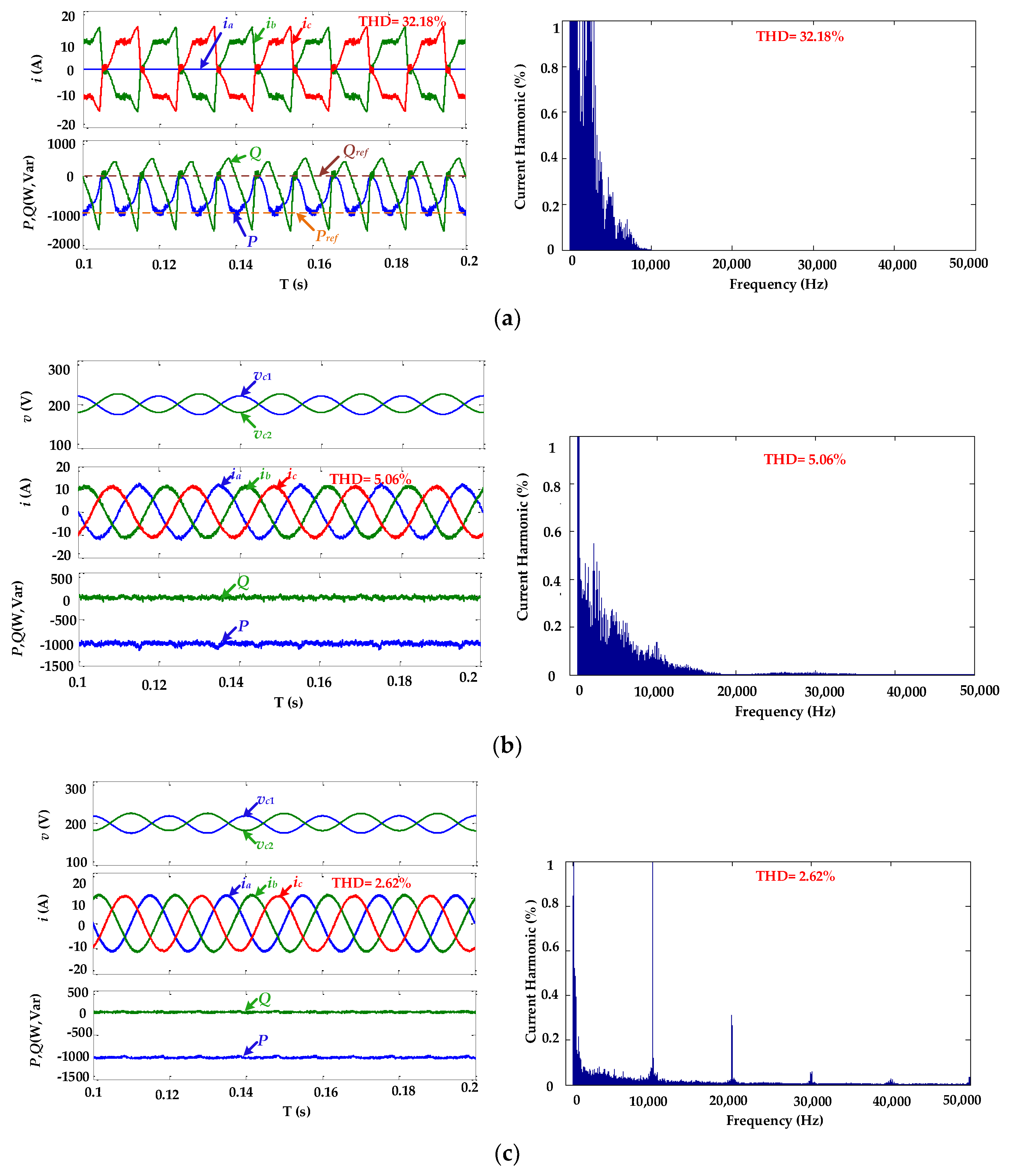
Figure 8 shows the BVSC simulation in the rectifier mode. The bridge arm of Phase A has an open-circuit fault. The given reference active power is –1000 W and the reference reactive power is 0 Var. DC-link voltage offset is restricted by cost function, and the weighting coefficient is 1000. The current THD under traditional MPDPC for a TPSS converter is 32.18%, with active power fluctuation from –1000 W to 0 W as shown in Figure 8a, whereas reactive power varies between –1500 Var and 500 Var. Poor waves indicate that the converter can’t work normally under a phase fault. For a fault-tolerant BVSC, the MPDPC under four vectors can maintain output power, tracking reference values, the current THD drops to 5.06%, and the two capacitor voltages are balanced as shown in Figure 8b, which proves that the fault-tolerant TPFS structure can keep the operation under a condition of a phase fault. Furthermore, the waves with the proposed CF-MPDPC for a fault-tolerant BVSC are better, and the current THD is 2.62% with balanced capacitor voltage. Most current harmonics focus on 10,000 Hz and 20,000 Hz, while low-frequency content is very small. The simulation results verify the effectiveness of the proposed method in a rectifier mode with a Phase A fault.
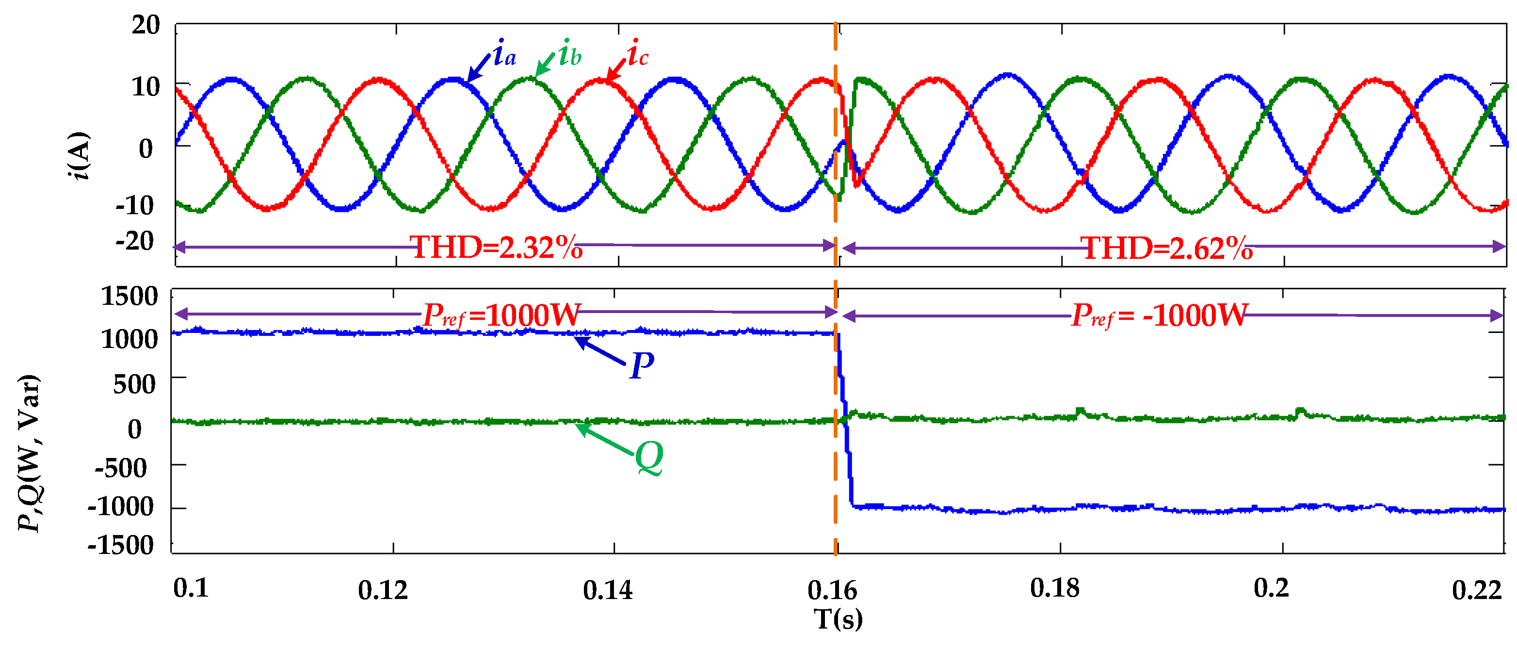
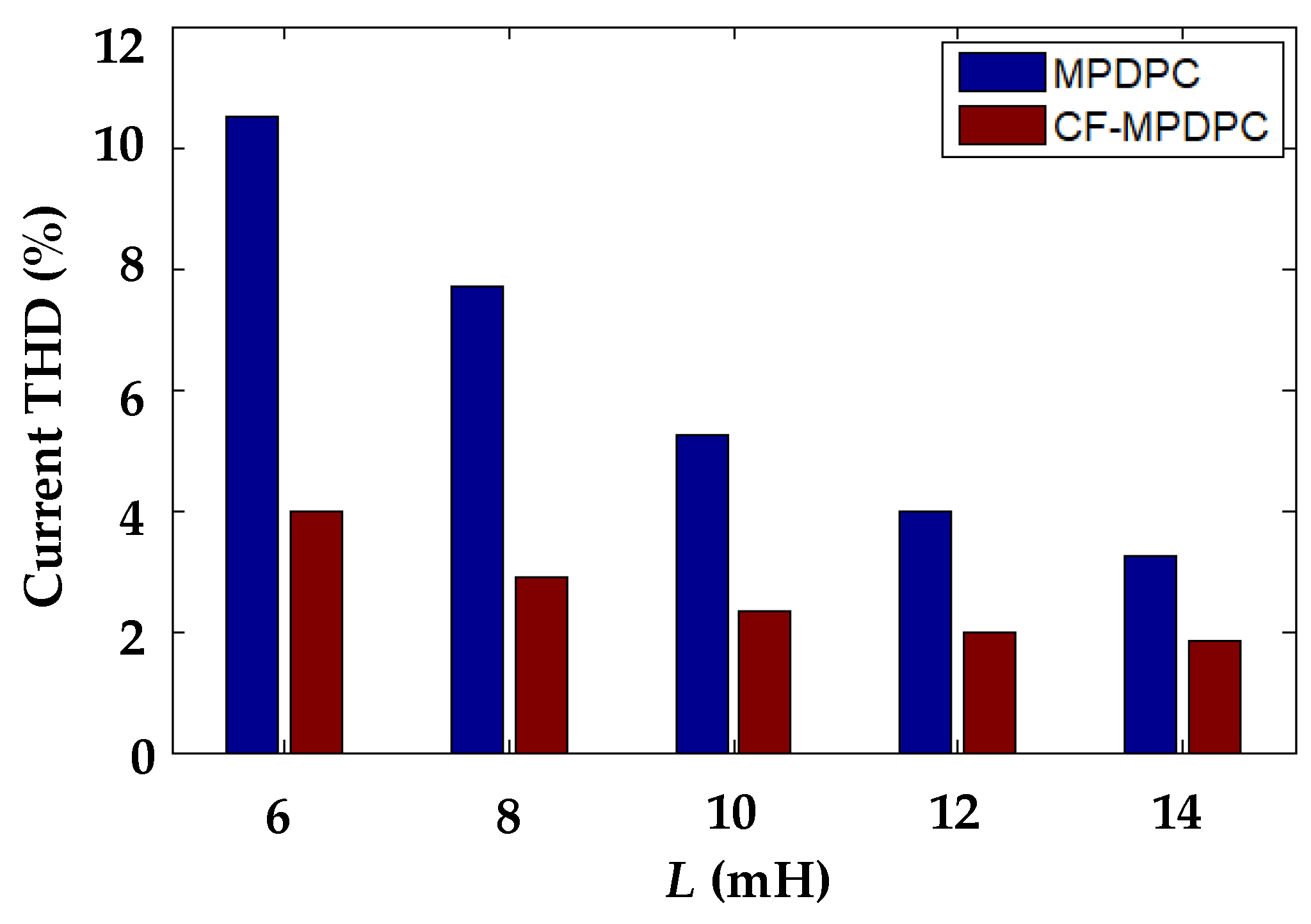
To verify the dynamic performance, the given reference active power changes from 1000 W to –1000 W, and reference reactive power is 0 Var. Figure 9 shows the simulation of switching between inverter and rectifier mode with the proposed CF-MPDPC. There is no serious distortion and overcurrent in the process of power change, and output power changes smoothly and stably tracks the reference value, which exhibits good dynamic control performance of the proposed method for step-changed power. Since the model predictive control is related to the parameters, various inductance values are used to verify the robustness of MPDPC and the proposed CF-MPDPC for a fault-tolerant TPFS converter. The given reference active power and reactive power are 1000 W and 0 Var. Current THD comparison is shown in Figure 10, and detailed THD values are displayed in Table 3. Current THD has small changes. with various inductance values under CF-MPDPC control. From the comparison, it can be seen that the proposed CF-MPDPC has stronger robustness than MPDPC. To verify the effect of changing sampling frequency on the results, sampling frequency is decreased from 20 kHz to 10 kHz. The reference active power and reactive power are 1000 W and 0 Var, respectively. The current THD of the MPDPC method increases from 5.23% to 9.7%. In contrast, the current THD for a fault-tolerant BVSC controlled by the proposed CF-MPDPC method rises from 2.32% to 3.1%, which shows good robustness.

4.2. Experiment Results for Fault-Tolerant BVSC

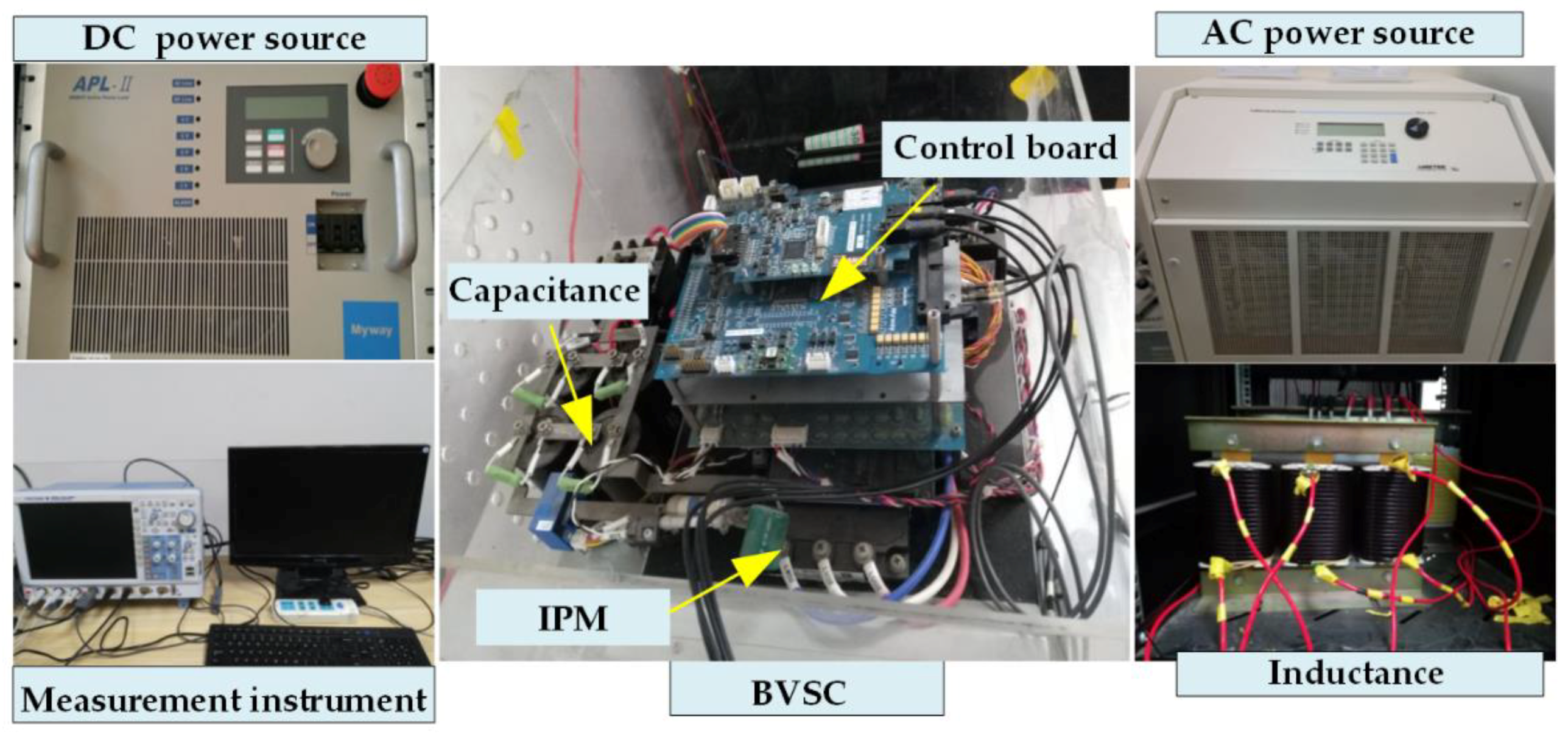
The experimental setup shown in Figure 11 is established to test the performance of the proposed CF-MPDPC strategy for a fault-tolerant BVSC. The main devices contain adjustable DC power source APL-II (Myway, Kanagawa, Japan), AC-programmable power AMETEK MX-30 (AMETEK Programmable Power, Inc., San Diego, CA, USA), and a BVSC hardware testbed based on PE-PRO, which is controlled by TI TMS320F28335 (Texas Instruments, Inc., Dallas, TX, USA). Experimental parameters are the same with the simulation parameters shown in Table 2.
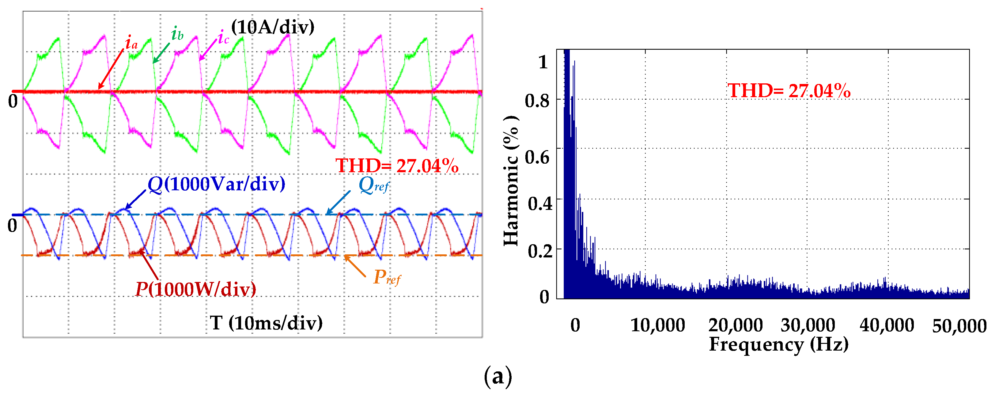
Figure 12 and Figure 13 exhibit the experimental results of BVSC with a Phase A fault in inverter mode and rectifier mode under three different control methods. The given reference active power in Figure 13 and Figure 14 is 1000 W and –1000 W, respectively. Reference reactive power is 0 Var in both inverter and rectifier mode. DC-link voltage offset is restricted by cost function in both MPDPC and CF-MPDPC for a fault-tolerant BVSC, and weighting coefficient λ is 1000. Current THD under traditional MPDPC for BVSC is 50.57% in inverter mode and 27.04% in rectifier mode. The current of the fault phase is zero because of the open circuit of the faulty bridge arm, and the other two currents have serious distortion, which can’t satisfy grid-connection requirements. The overfluctuation of output active power and reactive power show that the converter is not working properly, as shown in Figure 12a and Figure 13a. The waves under MPDPC for a fault-tolerant BVSC are improved by establishing a fault-tolerant structure and voltage vectors. The currents of three phases are sinusoidal with 5.26% THD in inverter mode and 5.53% THD in rectifier mode, with small fluctuations of output power, shown in Figure 12b and Figure 13b. By using the MPDPC based on three output vectors to approach the optimal vector and constant frequency on account of a fixed switching sequence for each sector, the current THD under the proposed CF-MPDPC for a fault-tolerant BVSC is 3.29% in inverter mode and 3.21% in rectifier mode, as shown in Figure 12c and Figure 13c, which are the best current waveforms of the three methods. The output active power and reactive power can track the reference values and remain more stable than MPDPC. The harmonic contents of the three methods are presented in Table 4. The low-frequency harmonics of the proposed CF-MPDPC for a fault-tolerant BVSC are reduced, and the high frequency of the current harmonics makes the filtering design easier. Furthermore, the voltages of the two capacitors are balanced in both MPDPC and CF-MPDPC for a fault-tolerant BVSC due to the term of DC-link voltage offset in the cost function. Steady experimental results verify the effectiveness of the proposed method in both inverter and rectifier modes.
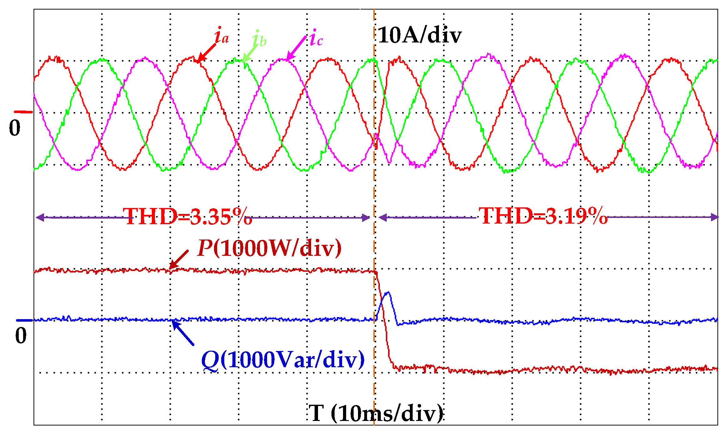
To test the performance of the proposed CF-MPDPC for a fault-tolerant TPFS converter with a dynamic power process, the reference active power changes from 1000 W to –1000 W, and the reactive power keeps at 0 Var to realize unit power factor grid-connected control. The bridge arm of Phase A has a fault, and the corresponding bidirectional switch is closed to connect the fault phase to the center point of the DC-link capacitors to form a TPFS fault-tolerant structure. As shown in Figure 14, the sinusoidal three-phase current waveforms can rapidly and stably follow the power without current shocks and increased harmonics. The output power can accurately track the reference values with good dynamic characteristics, which exhibits good performance of the proposed method.
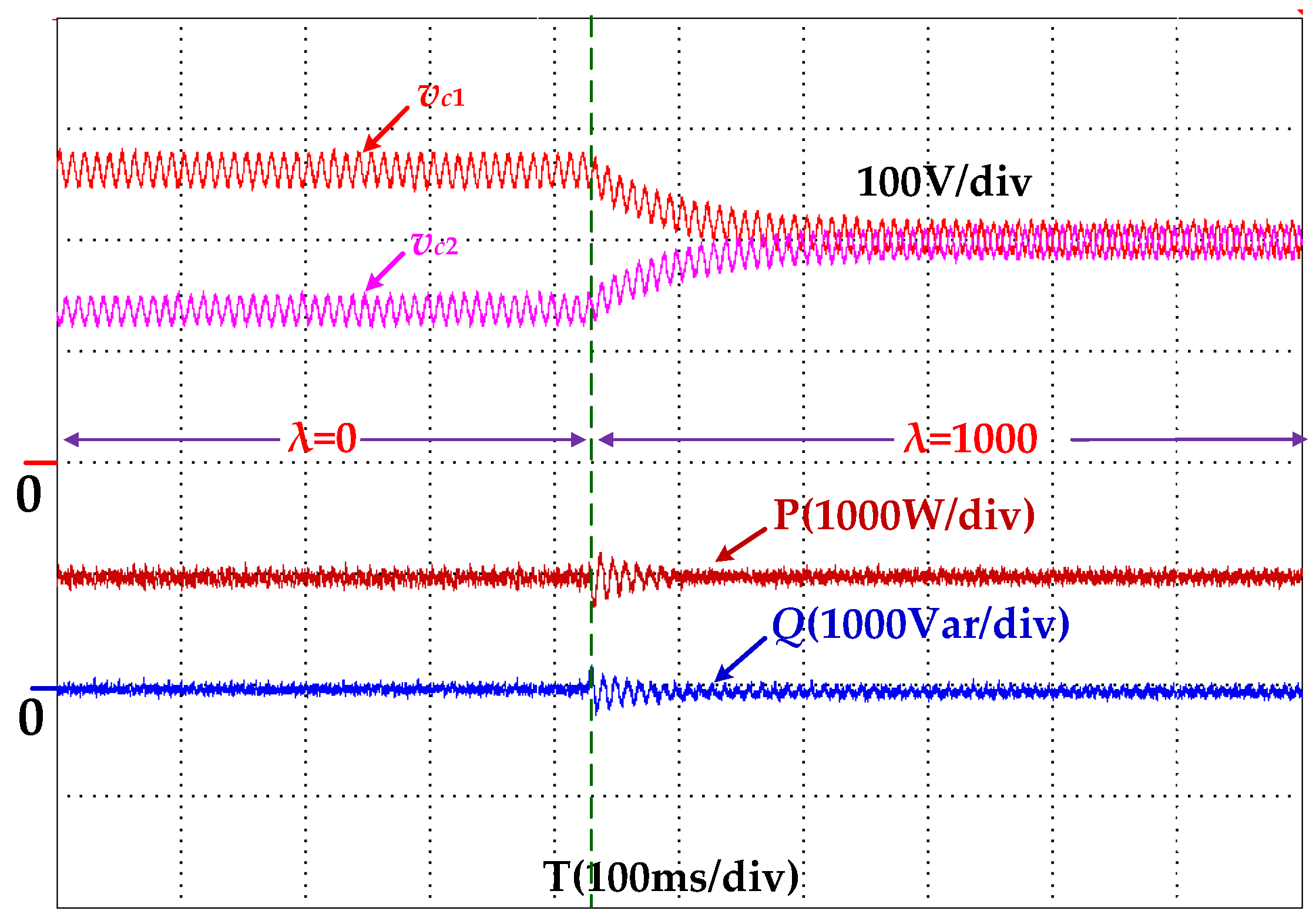
As shown in Figure 15, the center point of DC-link voltage for a fault-tolerant BVSC is unbalanced when weighting coefficient λ = 0, which represents that DC voltage-offset Δvdc isn’t restricted. Voltage vc1 fluctuates around 270 V, while voltage vc2 near 130 V, which threatens the long-term safe operation of capacitors. When the term of DC-link voltage offset is added to the cost function and weighting coefficient λ = 1000, the output power of BVSC can quickly remain stable and the balance center point of DC-link voltage is achieved with the voltages of two capacitors close to 200 V, which is half of the DC-link voltage. Weighting coefficient is obtained by repeated experiments, and the optimal coefficient is selected as the final value, which realizes the minimum power ripples and fast balance of the DC-link midpoint voltage.
From the simulation and experimental results, the proposed CF-MPDPC for TPFS converter has lower harmonics and smaller power ripples than traditional MPDPC for BVSC and MPDPC for a TPFS converter, which shows good static and dynamic performance with a switching device fault. Furthermore, the dynamic experimental results of switching between inverter and rectifier mode exhibit good dynamic response when reference power is changed. Finally, the experiment of DC-link midpoint voltage-offset suppression indicates that the proposed strategy can balance the voltages of two capacitors, which is beneficial to the safe and reliable operation for BVSC in the condition of a phase fault.

5. Conclusions

This paper proposes a constant-frequency model predictive direct power control method for fault-tolerant BVSC, which improves the performance of a BVSC with a phase fault. The following conclusions can be obtained through theoretical modeling, establishment of a control strategy, and simulation and experimental results.
  • Through fault-tolerant operation analysis of a TPFS structure, the output voltages in an αβ stationary frame and the corresponding voltage vectors with a phase fault were established. Then, the predictive power model and DC-link voltage offset were obtained to prepare for the control strategy.
  • The CF-MPDPC method was proposed to realize direct power control based on three output vectors with constant frequency, which can more accurately track the optimal vector and reduce current harmonics. Furthermore, the balance control of DC-link capacitor voltages was also achieved to protect the converter against second faults with an electrolytic capacitor for overvoltage operations by adding the term of a DC-link center-point voltage offset into the cost function.
  • From the simulation and experimental results, it can be seen that the proposed CF-MPDPC for a fault-tolerant TPFS converter outperforms the traditional MPDPC for BVSC and MPDPC for a fault-tolerant TPFS converter in both inverter mode and rectifier mode, with lower harmonics and power ripples. In addition, good performance when the reference power dynamically changed and DC-link midpoint voltage-offset suppression occurred makes the proposed CF-MPDPC strategy more applicable to fault-tolerant BVSC control with a phase fault.
  • The proposed CF-MPDPC for a fault-tolerant BVSC can maintain continuous operation with low harmonic content current and stable output power in the condition of a bridge-arm fault, which enhances the reliability and fault-tolerant operation capability of BVSC.

Author Contributions

S.H. surveyed the backgrounds, contributed to the establishment of themodel, controller design, simulation, and experimentconstruction. G.L., N.J., and L.G. contributed to the guidance of the simulation and experiments.

Funding

This research was funded by [National Science Foundation of China] grant number [51177040, 51607159, 51707176] and the APC was funded by [51177040].

Acknowledgments

This work is supported by the National Science Foundation of China (NSFC) under Grants 51177040, 51607159, 51707176 and the Science & Technology Innovation Talents in Universities in Henan Province 18HASTIT025, 172102410068, 2015GGJS-180, 18A470020.

Conflicts of Interest

The authors declare no conflict of interest.

References

  1. Ganesan, S.I.; Pattabiraman, D.; Govindarajan, R.K.; Rajan, M.; Nagamani, C. Control Scheme for a Bidirectional Converter in a Self-Sustaining Low-Voltage DC Nanogrid. IEEE Trans. Ind. Electron. 2015, 62, 6317–6326. [Google Scholar] [CrossRef]
  2. Mohammadi, M.R.; Farzanehfard, H. Family of Soft-Switching Bidirectional Converters with Extended ZVS Range. IEEE Trans. Ind. Electron. 2017, 64, 7000–7008. [Google Scholar] [CrossRef]
  3. Sun, K.; Wang, X.; Li, Y.W.; Nejabatkhah, F.; Mei, Y.; Lu, X. Parallel Operation of Bidirectional Interfacing Converters in a Hybrid AC/DC Microgrid Under Unbalanced Grid Voltage Conditions. IEEE Trans. Power Electron. 2017, 32, 1872–1884. [Google Scholar] [CrossRef]
  4. Vekhande, V.; Kanakesh, V.K.; Fernandes, B.G. Control of Three-Phase Bidirectional Current-Source Converter to Inject Balanced Three-Phase Currents Under Unbalanced Grid Voltage Condition. IEEE. Trans. Power Electron. 2016, 31, 6719–6737. [Google Scholar] [CrossRef]
  5. Wai, R.; Liaw, J. High-Efficiency-Isolated Single-Input Multiple-Output Bidirectional Converter. IEEE Trans. Power Electron. 2015, 30, 4914–4930. [Google Scholar] [CrossRef]
  6. Biricik, S.; Komurcugil, H. Three-level hysteresis current control strategy for three-phase four-switch shunt active filters. IET Power Electron. 2016, 9, 1732–1740. [Google Scholar] [CrossRef]
  7. Diab, M.S.; Elserougi, A.; Massoud, A.M.; Abdel-Khalik, A.S.; Ahmed, S. A Four-Switch Three-Phase SEPIC-Based Inverter. IEEE Trans. Power Electron. 2015, 30, 4891–4905. [Google Scholar] [CrossRef]
  8. Lu, J.; Hu, Y.; Zhang, X.; Wang, Z.; Liu, J.; Gan, C. High-Frequency Voltage Injection Sensorless Control Technique for IPMSMs Fed by a Three-Phase Four-Switch Inverter with a Single Current Sensor. IEEE/ASME Trans. Mechatron. 2018, 23, 758–768. [Google Scholar] [CrossRef]
  9. Xia, C.; Wu, D.; Shi, T.; Chen, W. A Current Control Scheme of Brushless DC Motors Driven by Four-Switch Three-Phase Inverters. IEEE J. Emerg. Sel. Top. Power Electron. 2017, 5, 547–558. [Google Scholar] [CrossRef]
  10. Zaky, M.S.; Metwaly, M.K. A Performance Investigation of a Four-Switch Three-Phase Inverter-Fed IM Drives at Low Speeds Using Fuzzy Logic and PI Controllers. IEEE Trans. Power Electron. 2017, 32, 3741–3753. [Google Scholar] [CrossRef]
  11. Zeng, Z.; Zheng, W.; Zhao, R. Performance Analysis of the Zero-Voltage Vector Distribution in Three-Phase Four-Switch Converter Using a Space Vector Approach. IEEE Trans. Power Electron. 2017, 32, 260–273. [Google Scholar] [CrossRef]
  12. Zeng, Z.; Zheng, W.; Zhao, R.; Zhu, C.; Yuan, Q. Modeling, Modulation, and Control of the Three-Phase Four-Switch PWM Rectifier Under Balanced Voltage. IEEE Trans. Power Electron. 2016, 31, 4892–4905. [Google Scholar] [CrossRef]
  13. Li, R.; Adam, G.P.; Holliday, D.; Fletcher, J.E.; Williams, B.W. Hybrid Cascaded Modular Multilevel Converter With DC Fault Ride-Through Capability for the HVDC Transmission System. IEEE Trans. Power Deliv. 2015, 30, 1853–1862. [Google Scholar] [CrossRef]
  14. Liu, J.; Tai, N.; Fan, C. Transient-Voltage-Based Protection Scheme for DC Line Faults in the Multiterminal VSC-HVDC System. IEEE Trans. Power Deliv. 2017, 32, 1483–1494. [Google Scholar] [CrossRef]
  15. Mobarrez, M.; Kashani, M.G.; Bhattacharya, S. A Novel Control Approach for Protection of Multiterminal VSC-Based HVDC Transmission System Against DC Faults. IEEE Trans. Ind. Appl. 2016, 52, 4108–4116. [Google Scholar] [CrossRef]
  16. Song, Z.; Tian, Y.; Chen, Z.; Hu, Y. Enhanced predictive current control of three-phase grid-tied reversible converters with improved switching patterns. Energies 2016, 9, 41. [Google Scholar] [CrossRef]
  17. Errouissi, R.; Muyeen, S.M.; Al-Durra, A.; Leng, S. Experimental Validation of a Robust Continuous Nonlinear Model Predictive Control Based Grid-Interlinked Photovoltaic Inverter. IEEE Trans. Ind. Electron. 2016, 63, 4495–4505. [Google Scholar] [CrossRef]
  18. Kwak, S.; Mun, S. Model Predictive Control Methods to Reduce Common-Mode Voltage for Three-Phase Voltage Source Inverters. IEEE Trans. Power Electron. 2015, 30, 5019–5035. [Google Scholar] [CrossRef]
  19. Li, X.; Zhang, H.; Shadmand, M.B.; Balog, R.S. Model Predictive Control of a Voltage-Source Inverter With Seamless Transition Between Islanded and Grid-Connected Operations. IEEE Trans. Ind. Electron. 2017, 64, 7906–7918. [Google Scholar] [CrossRef]
  20. Liu, Y.; Abu-Rub, H.; Xue, Y.; Tao, F. A Discrete-Time Average Model-Based Predictive Control for a Quasi-Z-Source Inverter. IEEE Trans. Ind. Electron. 2018, 65, 6044–6054. [Google Scholar] [CrossRef]
  21. Mariéthoz, S.; Fuchs, A.; Morari, M. A VSC-HVDC Decentralized Model Predictive Control Scheme for Fast Power Tracking. IEEE Trans. Power Deliv. 2014, 29, 462–471. [Google Scholar]
  22. Nauman, M.; Hasan, A. Efficient Implicit Model-Predictive Control of a Three-Phase Inverter with an Output LC Filter. IEEE Trans. Power Electron. 2016, 31, 6075–6078. [Google Scholar] [CrossRef]
  23. Nguyen, H.T.; Jung, J. Disturbance-Rejection-Based Model Predictive Control: Flexible-Mode Design with a Modulator for Three-Phase Inverters. IEEE Trans. Ind. Electron. 2018, 65, 2893–2903. [Google Scholar] [CrossRef]
  24. Guo, Y.; Gao, H.; Wu, Q.; Zhao, H.; Østergaard, J.; Shahidehpour, M. Enhanced Voltage Control of VSC-HVDC-Connected Offshore Wind Farms Based on Model Predictive Control. IEEE Trans. Sustain. Energy 2018, 9, 474–487. [Google Scholar] [CrossRef]
  25. Ghanaatian, M.; Lotfifard, S. Control of Flywheel Energy Storage Systems in Presence of Uncertainties. IEEE Trans. Sustain. Energy 2018. [Google Scholar] [CrossRef]
  26. Xia, C.; Wang, M.; Song, Z.; Liu, T. Robust Model Predictive Current Control of Three-Phase Voltage Source PWM Rectifier with Online Disturbance Observation. IEEE Trans. Ind. Inform. 2012, 8, 459–471. [Google Scholar] [CrossRef]
  27. Zhang, Y.; Xie, W.; Li, Z.; Zhang, Y. Model Predictive Direct Power Control of a PWM Rectifier with Duty Cycle Optimization. IEEE Trans. Power Electron. 2013, 28, 5343–5351. [Google Scholar] [CrossRef]
  28. Tarisciotti, L.; Zanchetta, P.; Watson, A.; Bifaretti, S.; Clare, J.C. Modulated Model Predictive Control for a Seven-Level Cascaded H-Bridge Back-to-Back Converter. IEEE Trans. Ind. Electron. 2014, 61, 5375–5383. [Google Scholar] [CrossRef]
  29. Zhang, Y.; Xie, W.; Li, Z.; Zhang, Y. Low-Complexity Model Predictive Power Control: Double-Vector-Based Approach. IEEE Trans. Ind. Electron. 2014, 61, 5871–5880. [Google Scholar] [CrossRef]
  30. Tarisciotti, L.; Zanchetta, P.; Watson, A.; Clare, J.C.; Degano, M.; Bifaretti, S. Modulated Model Predictive Control for a Three-Phase Active Rectifier. IEEE Trans. Ind. Appl. 2015, 51, 1610–1620. [Google Scholar] [CrossRef]
  31. Tarisciotti, L.; Zanchetta, P.; Watson, A.; Wheeler, P.; Clare, J.C.; Bifaretti, S. Multiobjective Modulated Model Predictive Control for a Multilevel Solid-State Transformer. IEEE Trans. Ind. Appl. 2015, 51, 4051–4060. [Google Scholar] [CrossRef] [Green Version]
  32. Zhang, Y.; Yang, H. Generalized Two-Vector-Based Model-Predictive Torque Control of Induction Motor Drives. IEEE Trans. Power Electron. 2015, 30, 3818–3829. [Google Scholar] [CrossRef]
  33. Cho, Y.; Lee, K. Virtual-Flux-Based Predictive Direct Power Control of Three-Phase PWM Rectifiers with Fast Dynamic Response. IEEE Trans. Power Electron. 2016, 31, 3348–3359. [Google Scholar] [CrossRef]
  34. Fang, H.; Zhang, Z.; Feng, X.; Kennel, R. Ripple-reduced model predictive direct power control for active front-end power converters with extended switching vectors and time-optimised control. IET Power Electron. 2016, 9, 1914–1923. [Google Scholar] [CrossRef]
  35. Song, Z.; Tian, Y.; Chen, W.; Zou, Z.; Chen, Z. Predictive Duty Cycle Control of Three-Phase Active-Front-End Rectifiers. IEEE Trans. Power Electron. 2016, 31, 698–710. [Google Scholar] [CrossRef]
  36. Shabestari, P.M.; Ziaeinejad, S.; Mehrizi-Sani, A. Reachability analysis for a grid-connected voltage-sourced converter (VSC). In Proceedings of the 2018 IEEE Applied Power Electronics Conference and Exposition (APEC), San Antonio, TX, USA, 4–8 March 2018; pp. 2349–2354. [Google Scholar]
  37. Yazdani, A.; Iravani, R. Voltage-Sourced Converters in Power Systems: Modeling, Control, and Applications; John Wiley and Sons: Hoboken, NJ, USA, 2010. [Google Scholar]
Figure 1. Fault-tolerant topology of a bidirectional voltage-source converter (BVSC). (a) Fault-tolerant structure of BVSC; (b) three-phase four-switch (TPFS) structure with Phase A fault.
Energies 11 02692 g001
Figure 2. Voltage space vectors with a Phase A fault. (a)vc1 = vc2; (b) vc1 < vc2; (c) vc1 > vc2.
Energies 11 02692 g002
Figure 3. Model predictive control (MPC) principle.
Energies 11 02692 g003
Figure 4. Duration and operation sequence diagram of voltage vector under each sector.
Energies 11 02692 g004
Figure 5. Flow diagram of constant-frequency-MPC (CF-MPC) for fault-tolerant BVSC.
Energies 11 02692 g005
Figure 6. Constant-frequency model predictive direct power control (CF-MPDPC) structure for fault-tolerant BVSC.
Energies 11 02692 g006
Figure 7. Simulation results with a Phase A fault in inverter mode. (a) MPDPC for a three-phase six-switch (TPSS) converter. (b) MPDPC for TPFS. (c) proposed CF-MPDPC for TPFS.
Energies 11 02692 g007
Figure 8. Simulation results with a Phase A fault in rectifier mode. (a) MPDPC for TPSS. (b) MPDPC for TPFS. (c) Proposed CF-MPDPC for TPFS.
Energies 11 02692 g008
Figure 9. Dynamic simulation results of transition between inverter and rectifier mode with the proposed CF-MPDPC for a TPFS converter.
Energies 11 02692 g009
Figure 10. Current total harmonic distortion (THD) comparison for a fault-tolerant BVSC with various inductance values.
Energies 11 02692 g010
Figure 11. Experimental setup.
Energies 11 02692 g011
Figure 12. Experimental results of BVSC with a Phase A fault in inverter mode. (a) MPDPC for BVSC. (b) MPDPC for a TPFS converter. (c) Proposed CF-MPDPC for a TPFS converter.
Energies 11 02692 g012
Figure 13. Experimental results of BVSC with a Phase A fault in rectifier mode. (a) MPDPC for BVSC. (b) MPDPC for a TPFS converter. (c) Proposed CF-MPDPC for a TPFS converter.
Energies 11 02692 g013aEnergies 11 02692 g013b
Figure 14. Dynamic experimental results of transition between inverter and rectifier mode with the proposed CF-MPDPC.
Energies 11 02692 g014
Figure 15. Experimental results of the proposed CF-MPDPC with balanced capacitor voltage.
Energies 11 02692 g015
Table 1. Voltage vectors when switching device of Phase A has a fault.
Voltage VectorSwitching State (Sb, Sc)uαuβ
V1(0, 0)2vc2/30
V2(0, 1)(vc2vc1)/3 ( v c 1 + v c 2 ) / 3
V3(1, 0)(vc2vc1)/3 ( v c 1 + v c 2 ) / 3
V4(1, 1)−2vc2/30
Table 2. Simulation and experiment parameters.
SymbolSystem ParametersValue
vdcDC voltage400 V
C1, C2Capacitance1000 μF
LFilter inductance10 mH
RLine resistance0.2 Ω
eAC line voltage110 V
fGrid frequency50 Hz
λWeighting factor1000
fsSampling frequency20 kHz
Table 3. Current THD comparison for a fault-tolerant BVSC.
Inductance6mH8mH10mH12mH14mH
MPDPC10.5%7.7%5.23%3.98%3.23%
CF-MPDPC4%2.88%2.32%2%1.85%
Table 4. Experimental comparison of current THD.
Working ModeControl MethodTHD
Inverter modeMPDPC for BVSC50.57%
MPDPC for TPFS converter5.26%
CF-MPDPC for TPFS converter3.29%
Rectifier modeMPDPC for BVSC27.04%
MPDPC for TPFS converter5.53%
CF-MPDPC for TPFS converter3.21%