1. Introduction
With increasing promotion of energy-saving and emission-reduction policies in China, space heating and hot water supply modes are gradually being transformed from the ways for traditional small coal-fired boiler and scattered coal burning to a clean heat supply system, and that is so-called
Coal to Clean Energy or
Coal to Electricity. The clean heat supply is defined as using one or more clean or renewable energy, such as electricity (including heat pump system [
1,
2] and electric boiler), natural gas, biomass and solar energy, to achieve low emission and low energy consumption for heat supply process through a system of high efficient transmission and distribution network and buildings of energy-saving. In all the above mentioned clean and renewable energy resources, an air-source heat pump (ASHP) system is a kind of renewable energy device transferring heat energy from a low-temperature heat source to a high-temperature heat source called a heat sink, using a small amount of electricity [
2,
3]. As shown in
Table 1 (the calculation parameters see the literature [
4]), compared with the traditional heating way, the ASHP system not only can decrease the amount of primary energy consumption and pollutant emission but can reduce operation cost [
4,
5]. Therefore, the popularization of the ASHP system will contribute to the development of the clean heating industry in China. According to the development reports of ASHP market in China in the first half of 2017 and 2018, the number of new installations for the ASHP is increasing year by year, especially in the first half of 2017, its rate of increase is about 50%. In the first half of 2018, the share of ASHP systems in space heating can up to 30%. And the commercial space heating accounts for 12.5% of the heating market.
Frost formation will occur inevitably on the surface of the outdoor air heat exchanger for the ASHP system operating in a cold and humid environment, when the surface temperature is below both the dew point and the freezing point [
6,
7,
8]. During the early initial period of frost formation, the frost crystals depositing on the heat transfer surfaces play the roles of increasing surface area and surface roughness [
9,
10]. This may enhance the heat transfer between the surface and the outdoor air [
11,
12]. However, with the growth of frost layer, the frost accumulation may cause two problems as follows: (1) an increase in heat transfer resistance between the air and the cold surface and a decrease in heat transfer efficiency [
8]; (2) an increase in the resistance of air flowing through the heat exchanger, a reduction of air mass flow rate and an increase of pressure drop in the air-side and power consumption [
13,
14]. As a result, the COP of the ASHP system is significantly degraded [
15]. These have been extensively confirmed by scholars in the world. For example, Emery and Siegel [
16] previously reported that the heat transfer rate decreased by about 50–75% and the pressure drop increased dramatically because of the frost formation and accumulation on compact heat exchanger. And the recent results provided by Timmermann et al. [
17] also showed a similar trend. Moreover, Sanders [
18] indicated that the heat transfer capacity of the ASHP system could be reduced by more than 35% under frosting conditions. Kwak and Bai [
19] showed that under frosting conditions, the COP of the conventional ASHP unit was decreased by about 53% as operation time increased from 25 min to 100 min. In summary, the application of the ASHP system are limited in the cold and humid area.
To promote the rapid development of ASHP technology and the successful implementation of
Coal to Electricity policy in China, the anti-frosting and defrosting technologies are focused by researchers worldwide in recent years [
14]. According to the references, the anti-frosting technologies include changing the characteristics (temperature, velocity [
20], humidity [
21], pressure [
22] and purified air [
23]) of inlet ambient air, changing the cold surface temperature [
24], surface treatment [
25], changing the structure of air heat exchanger (fin-tube geometry [
26,
27,
28], fin spacing [
29,
30], fin type [
31,
32]), changing the interaction between air or frost layer and cold surface (electric field [
33], ultrasonic wave [
34], magnetic field [
35] and low frequency mechanical oscillation [
36]). And the defrosting technologies mainly have reverse cycle [
37], hot gas bypass [
38], electrical heating [
19,
39,
40], warm-air defrosting [
41], compressor shutdown [
42], hot water spray [
43], phase change heat storage, electric field [
44], ultrasonic wave [
45], magnetic field [
46], air-particle jet [
47], control strategy [
48] and waste heat recovery [
49,
50]. In the above various technologies, the conventional reverse cycle (in various units) and the hot gas bypass (in industry units) defrosting technologies are the most widely used. The surface treatment, the control strategy, the waste heat recovery, the phase change heat storage and the changing the structure of air heat exchanger technologies will have important development prospects in the future. Other technologies (e.g., magnetic field, air-particle jet, electric field and low frequency mechanical oscillation) are only in the research stage and are not applied in actual industrial production. In addition, the compressor shutdown, electrical heating and the hot water spray technologies will tend to be abandoned to promote and apply.
Although the performance of the ASHP system can be obviously improved using the defrosting and anti-frosting technologies mentioned above, no one can achieve frost-free operation of the system under frosting conditions while both the system performance and the indoor environment are not deteriorated. This means that the defrosting mode needs to be turned on periodically in winter. To solve the problem fundamentally, some scholars focus on investigating frost-free technology for the ASHP system operating in frosting region in recent years. And some frost-free air-source heat pump (FFASHP) systems have been developed in published research. These systems can realize frost-free operation under frosting conditions, while taking heat energy from the moist air and releasing the heat to refrigerant [
51,
52,
53]. Through extensive consulting literature materials, it can be found that the articles related to the frost-free technology focus mainly on studies published from 2010–2018. To provide an effective tool for scholars and equipment manufacturers to promote the implementation of
Coal to Electricity policy in China, this paper will review the existing frost-free technologies in the published literature, based on the analysis of frosting phenomenon.
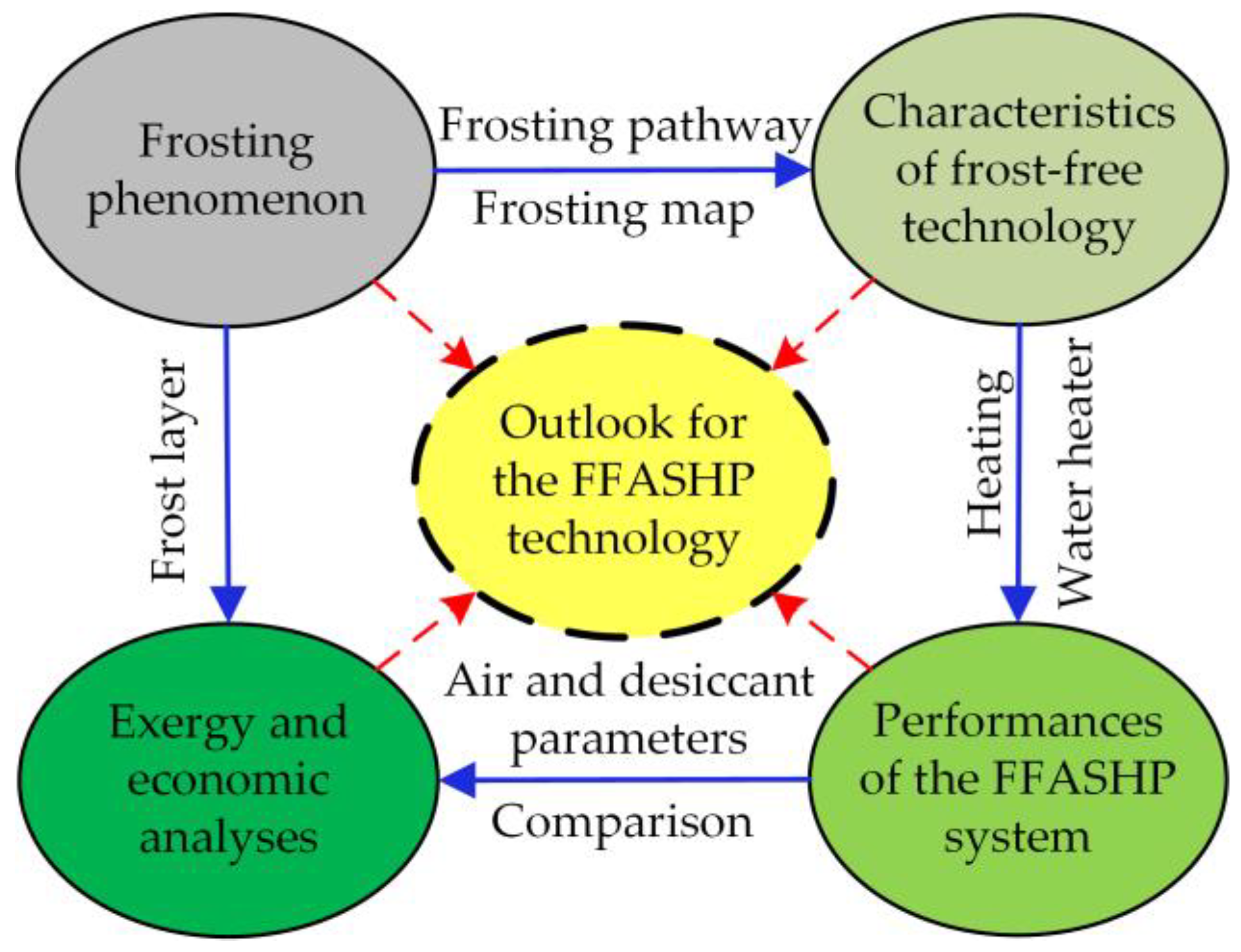
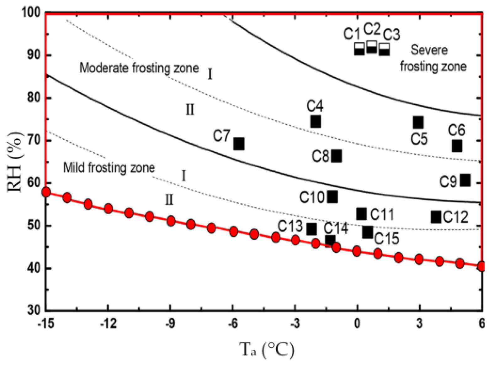
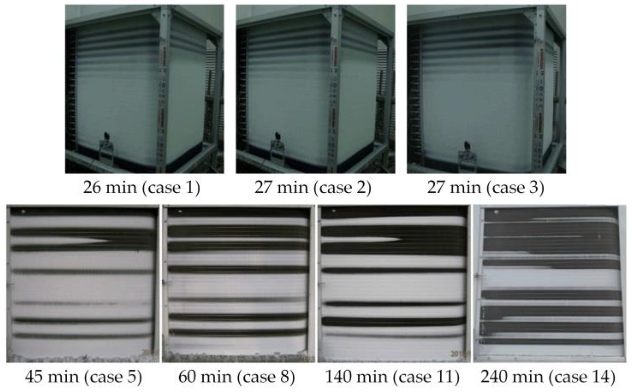
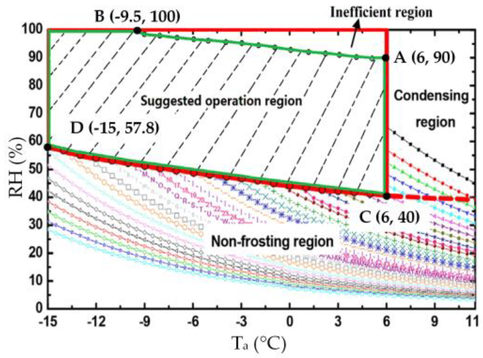
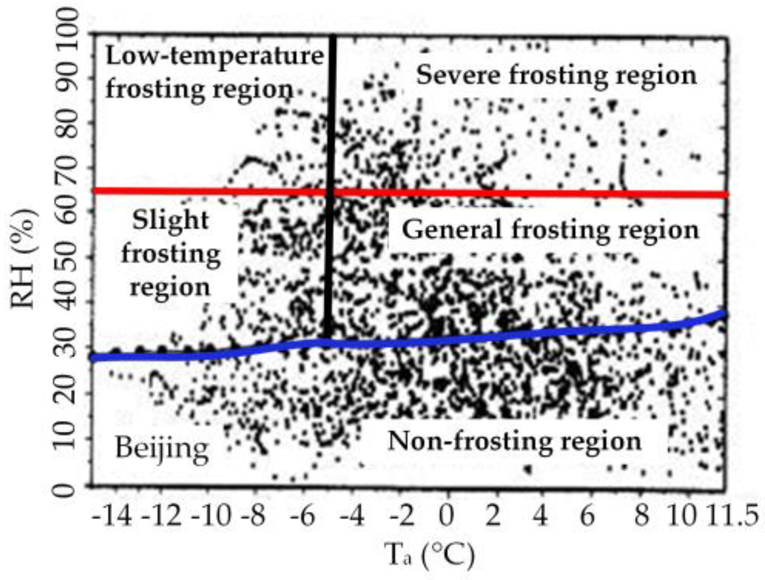
The roadmap of this paper is shown in
Figure 1. The frost formation phenomenon on the surface of outdoor air heat exchanger for the ASHP system will be firstly analyzed and summarized from frosting pathway and frosting map, respectively. Secondly, the characteristics of the frost-free technology will be summarized and presented. And then the performances of the FFASHP heating and the FFASHP water heater system proposed in recent years will be reviewed and compared with that of conventional ASHP system. At the same time, the exergy analysis of a FFASHP system will be carried out, and its extra investment cost and payback period will be also estimated. Finally, combined with the frosting phenomenon, the future researches to develop the frost-free technology for the ASHP system will be given from four aspects: optimization of system performance, new material (liquid/solid desiccant), new method, optimization of the control strategy.
3. Characteristics of Different Frost-Free Technologies
To solve frosting problem for the ASHP system, a new technology has been studied to prevent frost layer from forming on the outdoor air heat exchanger surface, and that is the so-called frost-free technology for the ASHP system. This technology can realize the frost-free operation of the ASHP system in the frosting region via adding a dehumidification system to decrease phase change driving force.
The common air dehumidification technologies include solution dehumidification [
75], solid dehumidification [
76], heating ventilating air conditioning dehumidification [
77], membrane-based air dehumidification [
78], cooling dehumidification and waste heat recovery. Among them, the solution dehumidification [
79] and the solid dehumidification [
80] were mainly applied to realize the frost-free operation of the ASHP system. In addition, the exhaust air heat recovery was also used to study the frost-free technology of the ASHP system, and the experiment proved that this system could keep the evaporator frost-free at the air temperature of −20 °C [
81]. Because this frost-free technology is currently published in one article, we do not make detailed analysis in this paper.
In recent years, many researchers focus primarily on the investigation of following two FFASHP system: (1) integrated with a liquid desiccant device; (2) coupled a solid desiccant-coated heat exchanger. As seen in
Table 3, among both them, the former is usually used for a FFASHP heating system, and the latter was used for a FFASHP water heater system. In this section, the characteristics of two frost-free technologies are mainly summarized and presented.
3.1. Frost-Free Technology for an ASHP Heating System
3.1.1. FFASHP Heating System Description
(1) Main components of system
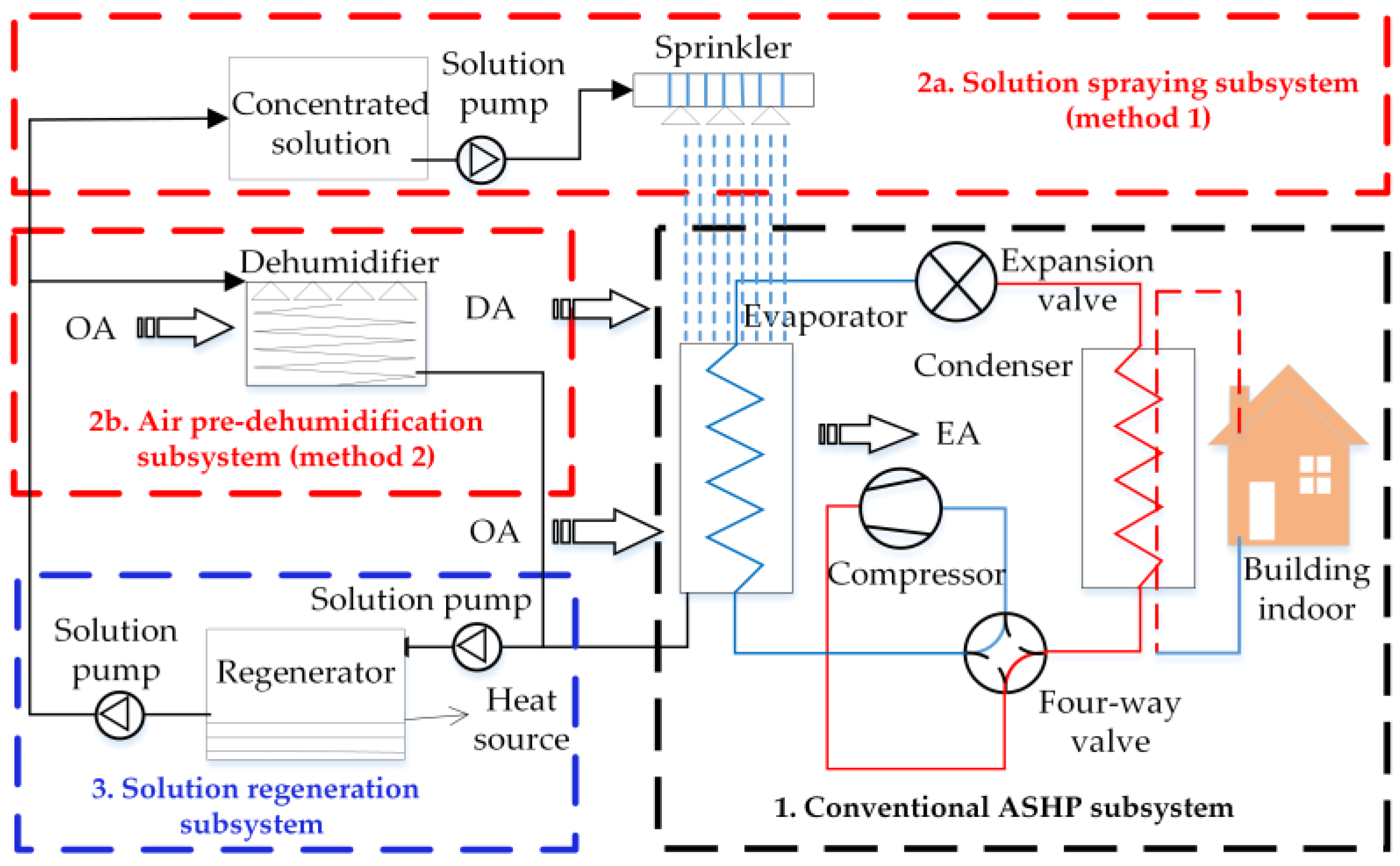
Figure 13 indicates schematic diagrams of two FFASHP heating systems based on the liquid dehumidification method. As we can see from
Figure 13, the FFASHP heating system based on method 1 consists of a conventional ASHP subsystem, a solution spray subsystem and a solution regeneration subsystem. Another FFASHP heating system based on method 2 consists of a conventional ASHP subsystem, an air pre-dehumidification subsystem and a solution regeneration subsystem. Three subsystems in the above two FFASHP heating system contain the following components: evaporator, condenser, expansion valve, compressor, four-way valve, solution pump, sprinkler, solution tank or dehumidifier and regenerator. It should be noted that
Figure 13 only gives simple schematic diagrams of the systems and their detailed structures can be referred to the relevant references [
79,
84,
87].
(2) Main parameters
For the FFASHP heating system based on method 1, the parameters of the test room and main components are listed in
Table 4. To simulate a frosting environment, an air conditioner, a heater and three humidifiers were used to adjust the air parameters of the test room. The heating and cooling capacities of the air conditioner were 3.5 kW and 2.5 kW, respectively [
79]. Through keeping constant frosting environment and indoor environment, the experiments were carried out by Jiang et al. [
79] under the operation conditions shown in
Table 5.
For the FFASHP heating system based on method 2, the solution, the main components, the indoor and outdoor environment parameters in different studies are listed in
Table 6 and
Table 7.
Table 6 shows the parameters of numerical calculation of Zhang et al. [
84].
Table 7 summarizes the analysis calculation and design parameters when Su et al. [
73,
87] and Yongcun et al. [
53] analyzed the performance of this FFASHP heating system. And it also give the analysis parameters for a 150 m
2 apartment (keeping indoor temperature of 20 °C and humidity of 8.7 g/kg) [
82]. The thermodynamic properties of liquid desiccant solution can be calculated and obtained according to the formulas in literatures [
88,
89,
90].
(3) Operation process of system
During heating mode, the solution spray subsystem was closed in the FFASHP heating system based on method 1, when the outdoor ambient air temperature and RH were in the non-frosting area. On the contrary, when the outdoor environments were in the frosting area, the solution spray subsystem was operated, and the low freezing point solution was sprayed onto the air heat exchanger in the form of liquid films and liquid droplets [
79]. The outdoor air (OA) flowed into the air heat exchanger and was dehumidified by contacting the liquid films and the liquid droplets to decrease the dew point temperature, while the heat from the air was absorbed by the solution. And then the heat was released to the evaporator [
53,
91]. Thereby, two essential elements of frosting were avoided. This kind of FFASHP system will has a good prospect because its simple dehumidification component and relatively low manufacturing cost. And thus, in the
Section 5 of the present paper, the exergy and economic analysis of this frost-free system will be conducted.
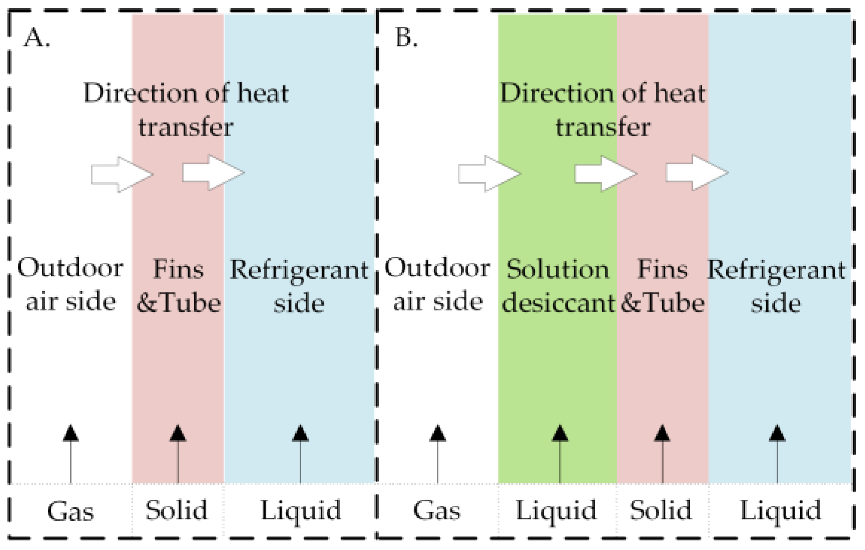
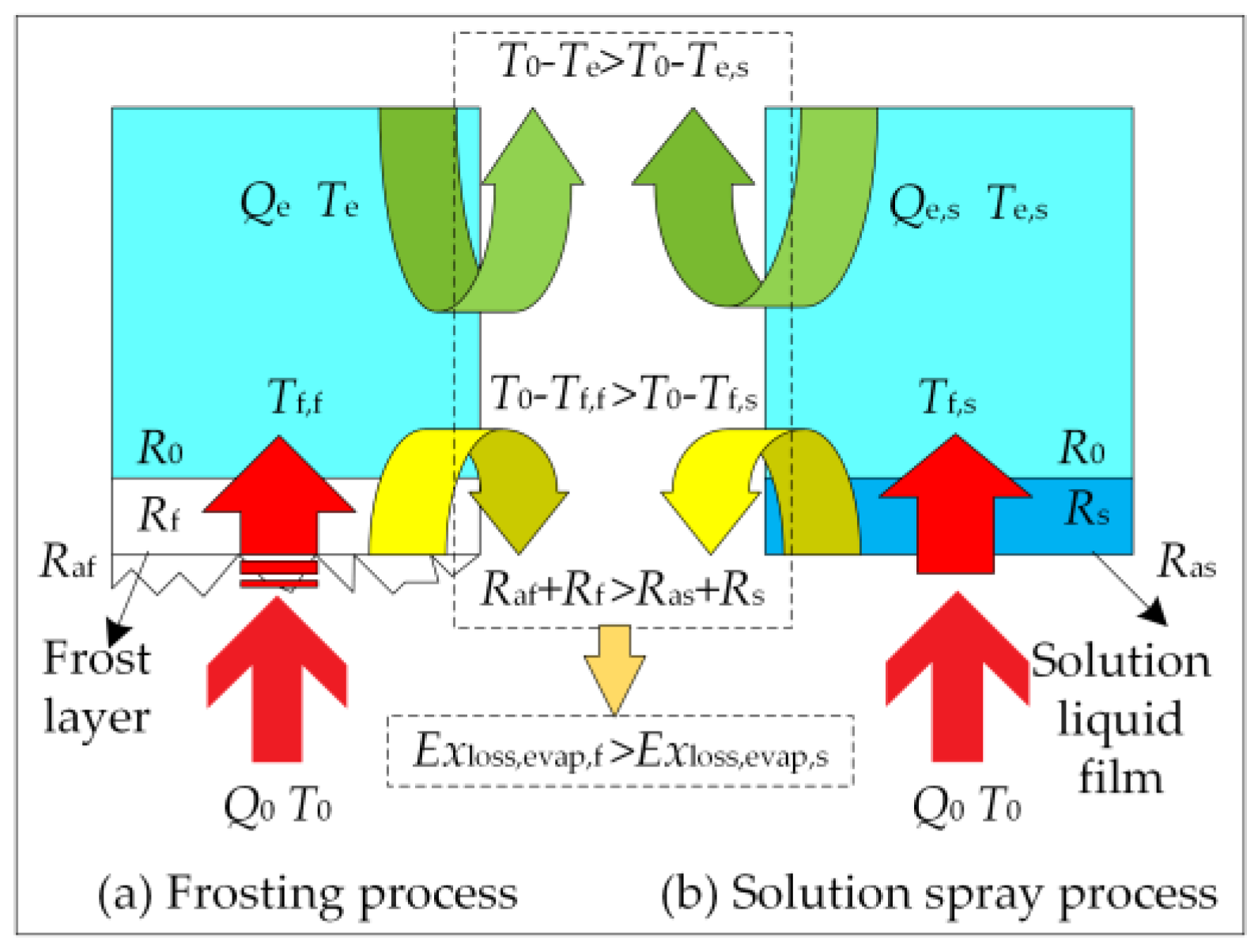
As a result of the application of the solution spray subsystem, the gas-solid-liquid heat transfer mode of outdoor air heat exchanger in the ASHP system is replaced by another heat transfer mode, which mainly depends on the coupled heat transfer of gas-liquid-solid-liquid composed of air, solution, fin and refrigerant, as shown in
Figure 14. It is common knowledge that the heat transfer coefficient of this new heat transfer mode is higher than that of the gas-solid-liquid heat transfer mode. However, if the liquid film of solution on the surface of heat exchanger is too thick, the air flow resistance and the thermal resistance between the air and the heat exchanger will increase, resulting in the system COP to decrease. Therefore, it is necessary to study the heat transfer enhancement technology of the gas-liquid-solid multiphase heat transfer process on the surface of the air-side fin-tube heat exchanger under the solution spray working condition.
For another FFASHP heating system based on an air pre-dehumidification subsystem [
84,
87] shown in
Figure 13, when the ambient air temperature and RH were in the frosting region, the air pre-dehumidification subsystem was opened, the outdoor air (OA) firstly passed through a dehumidifier to reduce the moisture content of the outdoor air and decreased the dew point of the air. Afterwards, the dry air (DA) flowed into the air heat exchanger to heat and evaporate the refrigerant in tube, and there was no frost on the air heat exchanger surface [
84].
Furthermore, for two FFASHP heating systems above, with increasing the moisture content of the liquid desiccant solution, the vapor partial pressure of the liquid desiccant is higher than that of the outdoor air, causing the decrease of its dehumidifying performance. Thus, to keep the continuous frost-free operation of the FFASHP heating system, the liquid desiccant solution should be regenerated in time.
3.1.2. Regeneration of Liquid Desiccant
Using renewable energy or waste heat to regenerate the desiccant material can not only improve the COP of ASHP system but reduce its operation cost. According to the published references, the regeneration methods of liquid desiccant were as follows: vapor compression system, electrical heater, waste heat, solar energy, ultrasonic and electro-osmosis [
92].
In these methods above, some have been used for regenerating the liquid desiccant to maintain continuous frost-free operation of the FFASHP systems. For example, Jiang et al. [
79] proposed using the condensation heat of refrigerant in summer to regenerate the spray solution. But this method led to the higher costs of investment and operation because a large amount of dehumidifying solution and large volume solution storage tanks were needed. Consequently, the application of this seasonal regeneration method is not recommended.
Zhang et al. [
82] utilized the vapor compression system to preheat the liquid desiccant before entering the regenerator and then fresh air flowed into the regenerator to be humidified by contact with hot liquid desiccant. Finally, the concentrated liquid desiccant was obtained. Yongcun et al. [
53] designed a multi-stage regenerator to improve the regeneration effectiveness. Although both the regeneration methods can increase the driving force of heat and mass transfer between the solution and the air while improving regeneration efficiency, these systems are more complicated. It will decrease the operation reliability of the system. Therefore, a simple and efficient regeneration method of the liquid desiccant should be explored in the future.
3.1.3. Liquid Desiccant
The characteristics of solution desiccant are crucial for the FFASHP heating system. Currently, the available dehumidifying solutions could be mainly classified into three categories [
79,
93,
94]: (1) organic solution (diethylene glycol, triethylene glycol, glycerol); (2) inorganic salt solution (LiCl, LiBr, CaCl
2); and (3) acid solution (H
2SO
4 and H
3PO
4). The characteristics of these solution desiccants are listed in
Table 8. It can be seen from the
Table 8 that two acid solutions are not suitable for the FFASHP system due to its strong toxicity and corrosivity. And the corrosivities of the organic solution desiccants on metal materials are lower than that of other solutions.
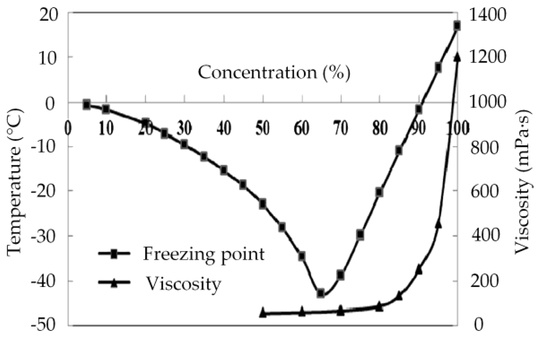
Through comparing to the properties of various solutions, Jiang et al. [
79] found that the glycerol aqueous solution was suitable as a spray solution for the frost-free system. As shown in
Figure 15, the concentration of glycerol aqueous solution should be below 80%. This main reason was that the viscosity of glycerol solution increased sharply when the concentration was over 80%. We also could see when the concentration of the solution was lower than 30%, its corresponding freezing point was too high so that dehumidifying capability was lost [
79]. As a result, the concentration of the glycerol solution selected was between 30% and 70% [
79,
95]. Even so, the glycerol aqueous solution was not optimum liquid desiccant for the frost-free technology of the ASHP system, because the energy consumption of its regeneration was high [
95].
Compared with the LiBr aqueous solution, the dehumidification capacity of LiCl aqueous solution was 20% higher than that under the same working condition. And the power consumption of pump can be 20% lower than it [
96]. As a result, LiCl solution was generally chosen by scholars as a desiccant for FFASHP system. For example, Su et al. [
73] and Zhang et al. [
82,
84] selected the lithium chloride aqueous solution to dehumidify the moist air before it entered the heat exchanger. In order to avoid the crystallization of the selected solution in the temperature range of the system operation, the solution concentration should be 25–45% [
95]. And the regeneration temperature was low within this concentration range, which can make better use of low-temperature heat source [
94]. However, the lithium chloride solution also cannot be used as the best desiccant to be recommended in FFASHP technology in the future because of its high price.
3.2. Frost-Free Technology for an ASHP Water Heater System
3.2.1. FFASHP Water Heater System Description
The FFASHP water heater system coupled a solid desiccant is generally composed of a conventional ASHP subsystem, a desiccant-coated heat exchanger [
83] or an extra heat exchanger coated by a solid desiccant with an energy storage device (EHECSD) [
10,
80]. The systems could not only prevent frosting in heating mode but supply uninterrupted heating in regeneration mode. It should be noted that the solid desiccant and the extra heat exchanger should be integrated [
80].
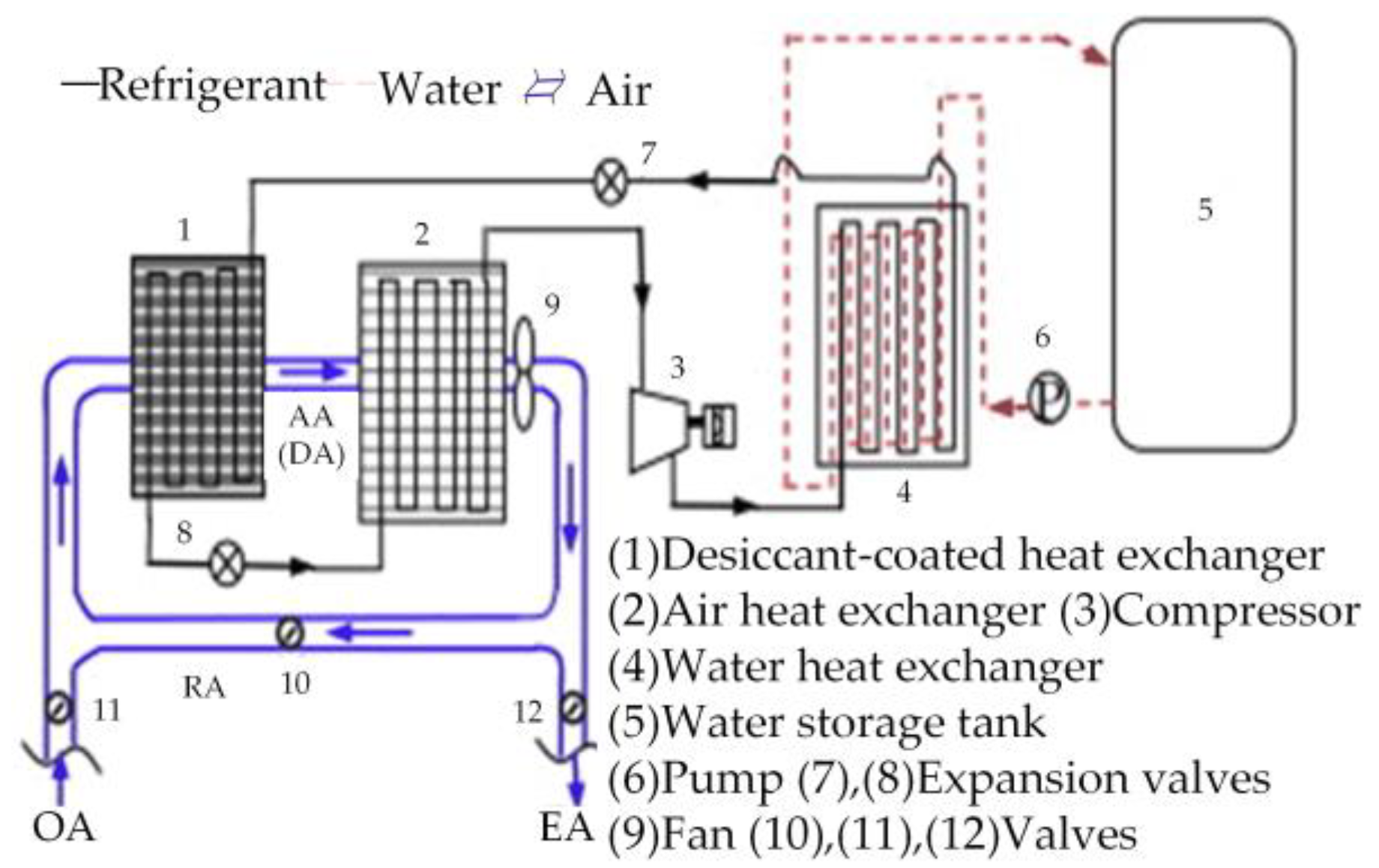
A schematic diagram of the FFASHP water heater system coupled a desiccant-coated heat exchanger is illustrated in
Figure 16. It mainly consists of a solid desiccant-coated heat exchanger, an air heat exchanger, a compressor, a water heat exchanger, a water tank. The parameters of the numerical calculation based on this system are listed in
Table 9.
In heating mode, the valves (11, 12) were opened and the valve (10) was closed. The extra heat exchanger coated by the solid desiccant in this system could dehumidify the outdoor air before entering the air heat exchanger, so that the dew point of the air entering the heat exchanger was decreased. Thus the frost-free operation of the system could be realized [
83].
With increasing moisture content of the solid desiccant, the vapor partial pressure of the desiccant was higher than that of the outdoor air and thus the system was switched to the regeneration mode. During regeneration mode, the valve (10) was opened and the valves (11, 12) were closed. The refrigerant was discharged from the compressor and passed through the water tank, flowed through the desiccant-coated heat exchanger to heat the air and to regenerate the desiccant. And then the refrigerant was throttled by the expansion valve (8), entered the air heat exchanger and was vaporized by hot and humid air [
83].
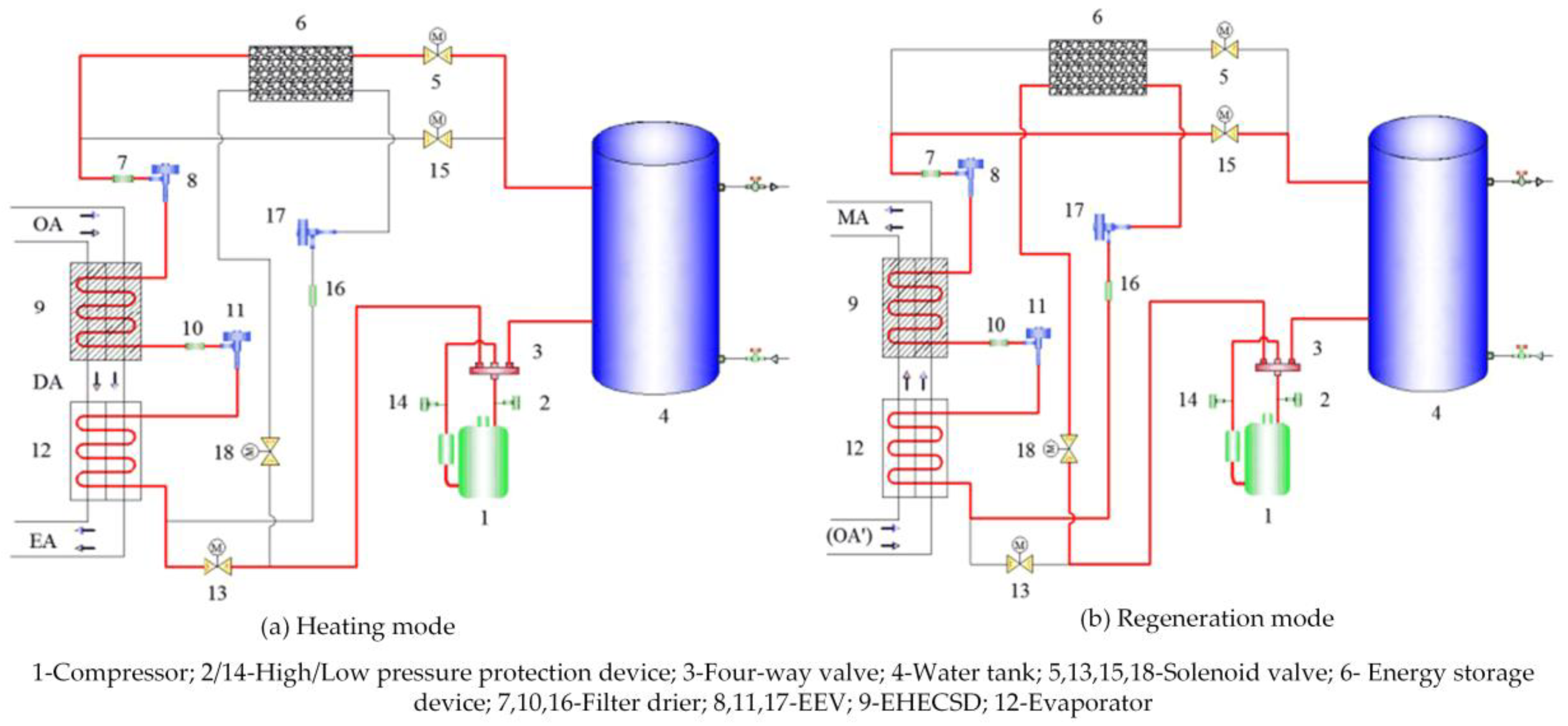
As shown in
Figure 17, the FFASHP water heater system combined with energy storage and dehumidification technology consists mainly of a compressor, a four-way valve, a water tank, an energy storage device (ESD), three electronic expansion valves (EEVs), an extra heat exchanger coated by a solid desiccant (EHECSD) and an outdoor air heat exchanger [
10,
80,
85]. The structural parameters of EHECSD and ESD, and the main characteristics of the measuring instrumentation are listed in
Table 10 and
Table 11, respectively. For this FFASHP water heater system, the operation conditions in different studies are summarized in
Table 12.
As we can see from
Figure 17a, in heating mode, the refrigerant passed through the four-way valve after being discharged from the compressor, flowed into the condenser and then run through the ESD where the condensation heat was absorbed. Afterwards, it was throttled by the EEV (8), entered the EHECSD in which the refrigerant absorbed latent heat released by water vapor from the air, and flowed into the evaporator. The dew point of the air was decreased, and thus the frost-free operation was realized [
85].
Figure 17b describes that in regeneration mode, the refrigerant was discharged from the compressor and passed through the four-way valve and the water tank, flows through the EHECSD, entered the evaporator, was throttled by the EEV (17), and then flowed through the ESD, finally returned the compressor to complete the regeneration process [
10]. In the period of regeneration cycle, the outdoor air was firstly preheated in the evaporator and then flowed through the EHECSD while the water vapor from the solid desiccant was removed [
10,
80].
3.2.2. Solid Desiccant
Commonly used solid desiccant materials in drying applications included the conventional physical desiccant (e.g., silica gel, molecular sieve and activated carbon) [
97] and the new compound desiccant consisting of physical and chemical desiccant (e.g., silica gel based composite desiccant, molecular sieve based composite desiccant and carbon based composite desiccant) [
98]. According to the references [
80,
83], the silica gel or silica gel based composite desiccant was usually used to dehumidify the outdoor air to realize frost-free operation of ASHP systems. This is because it is of great specific surface area (about 530 m
2/g) and good moisture adsorption capacity [
99].
As summarized in
Table 2, the solid desiccant was primarily applied to realize the frost-free operation of the ASHP water heater system and not used for the FFASHP heating system. This is due to the following three reasons: (1) a liquid desiccant system can be driven by low-temperature heat source in comparison with solid desiccant [
100]; (2) the power of ASHP heating system is larger than that of ASHP water heater system, that means a large demand for desiccant in the heating system; and (3) the price of the solid desiccant is more expensive in comparison with the liquid desiccant, resulting in increasing the cost of ASHP system.


