Asymptotic Output Tracked Artificial Immunity Controller for Eco-Maximum Power Point Tracking of Wind Turbine Driven by Doubly Fed Induction Generator


Abstract
1. Introduction
2. Wind Turbine and DFIG Modeling
2.1. Doubly Fed Induction Generator Model
- The flow distribution is sinusoidal.
- The air gap is constant.
- The influences of the heating and the skin effect are not considered.
- The saturation of the magnetic circuit is negligible.
2.2. Wind Turbine Model
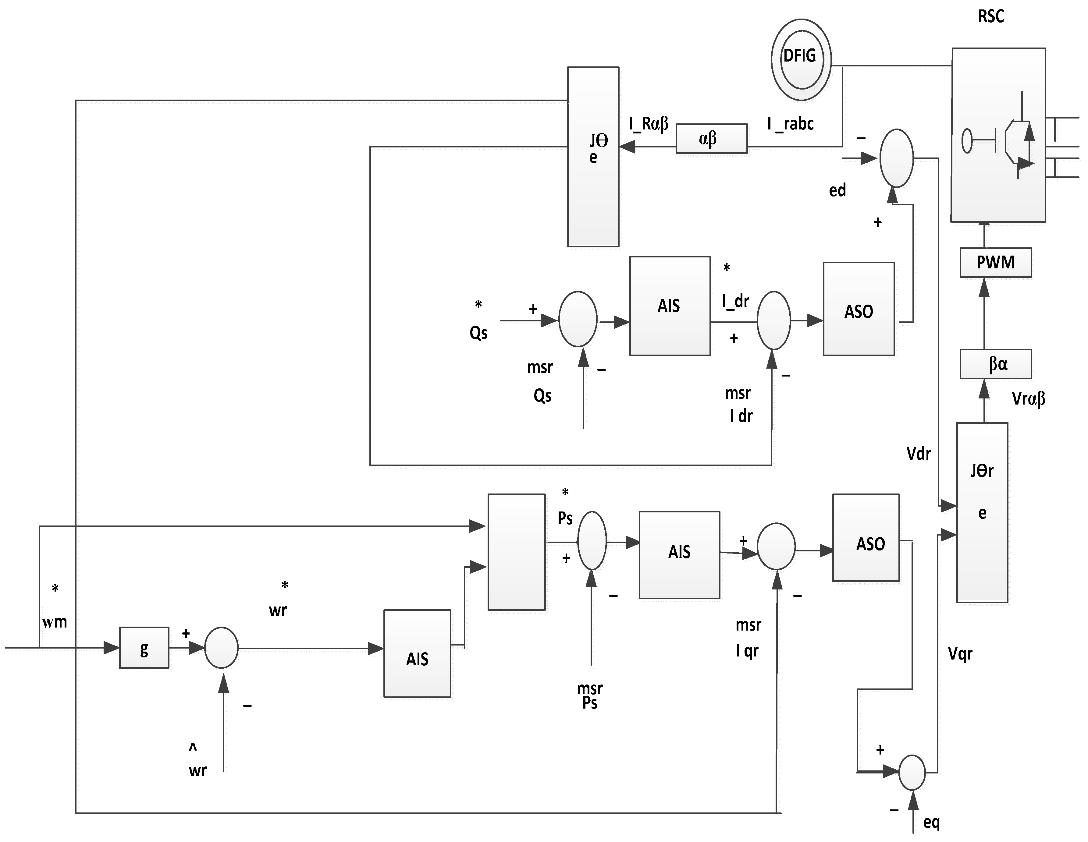
3. DFIG Control Strategy
4. AI MPPT Algorithm
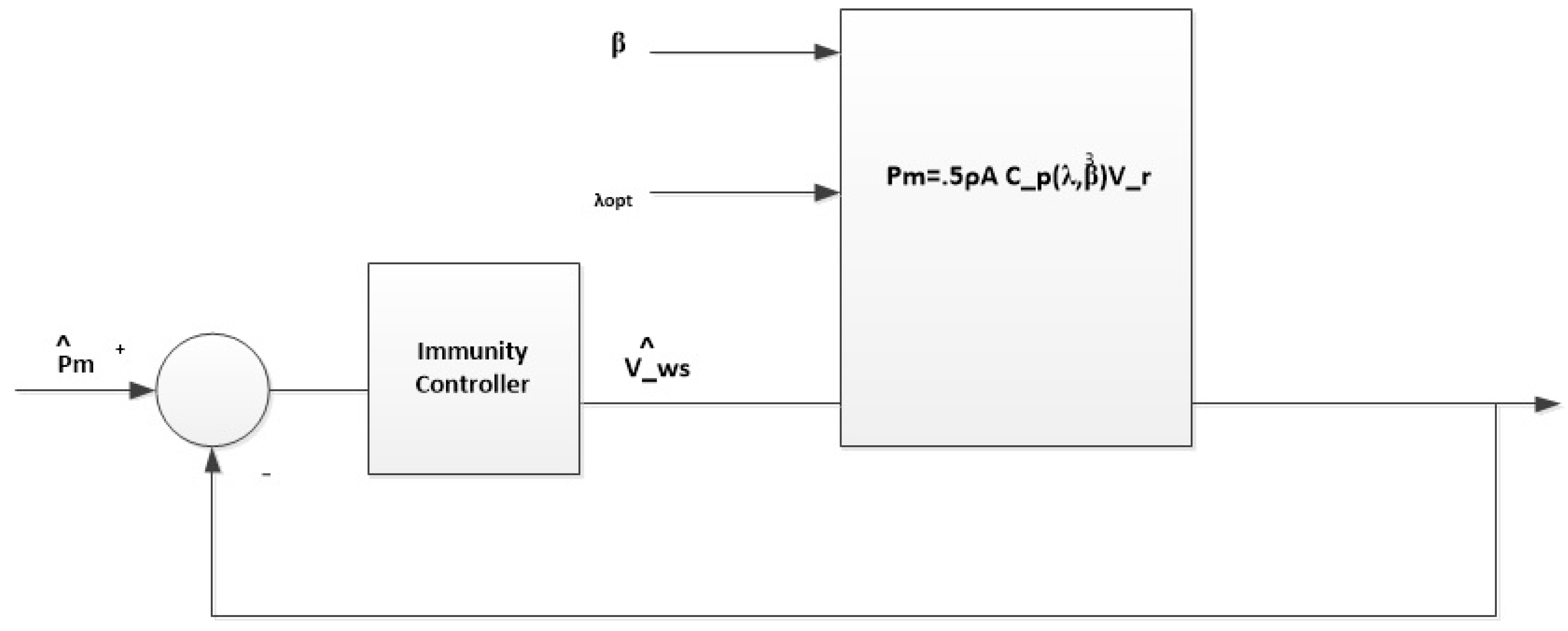
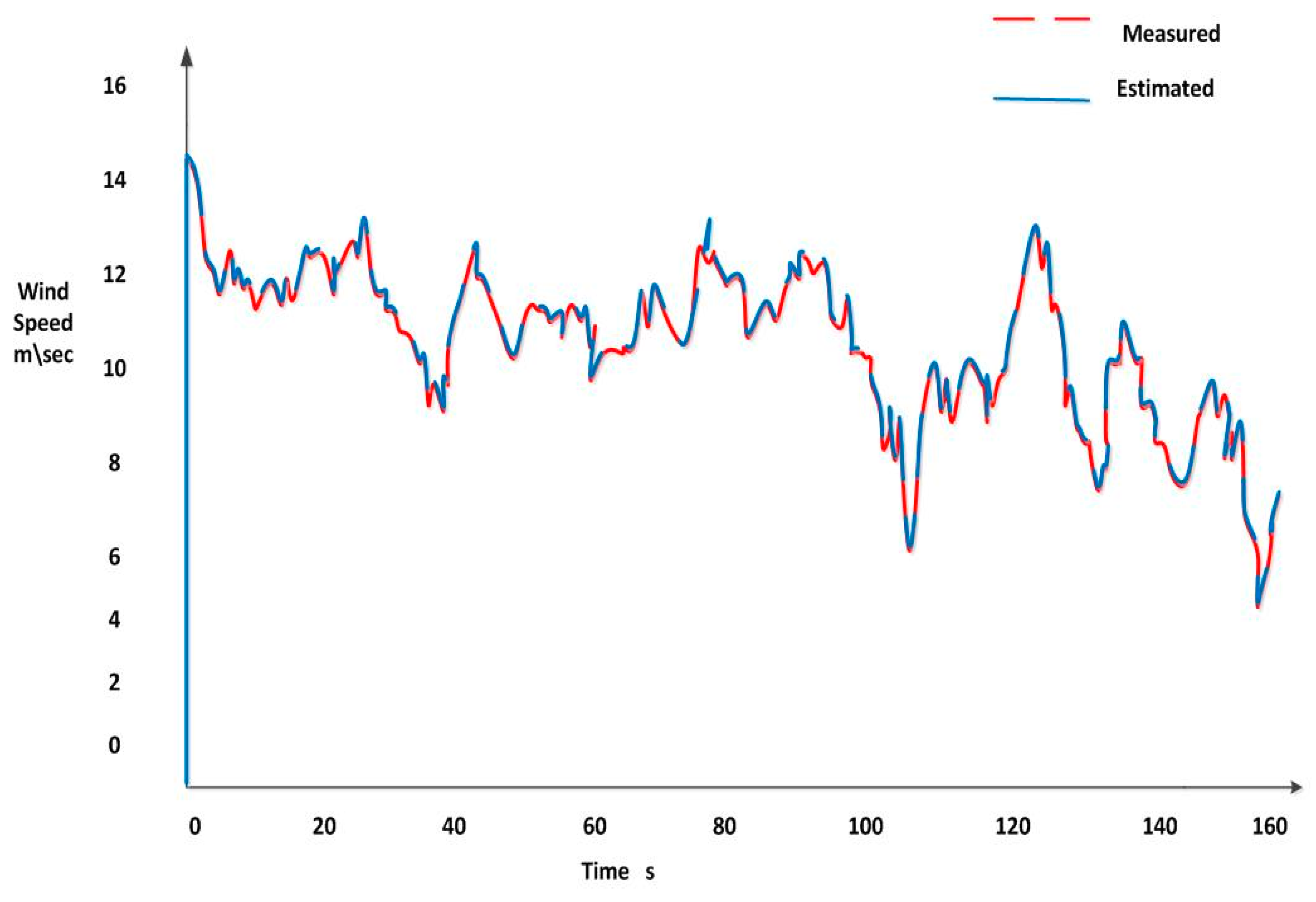
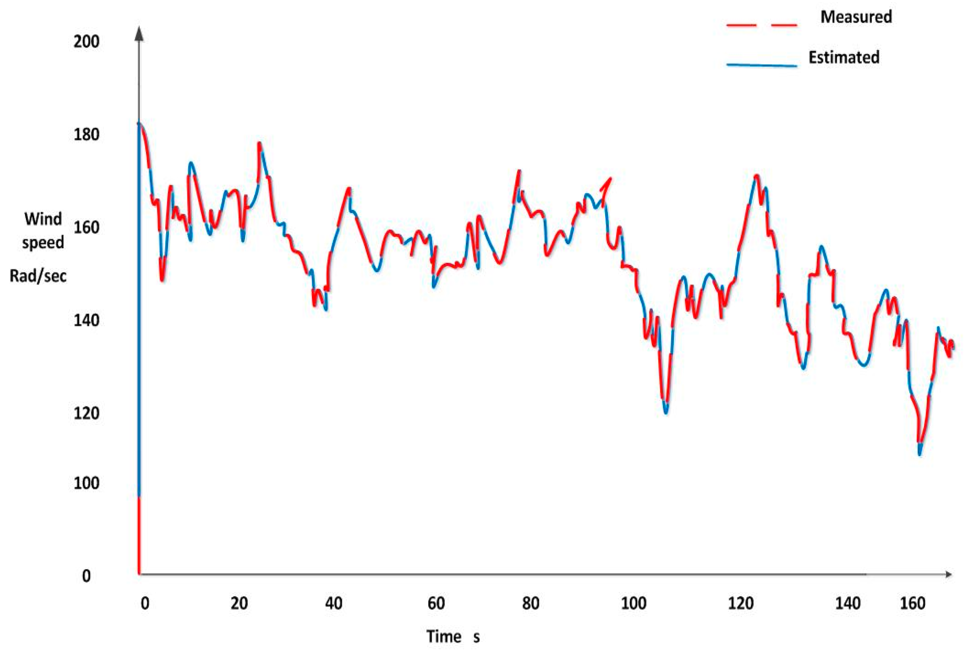
4.1. Wind Speed Estimation
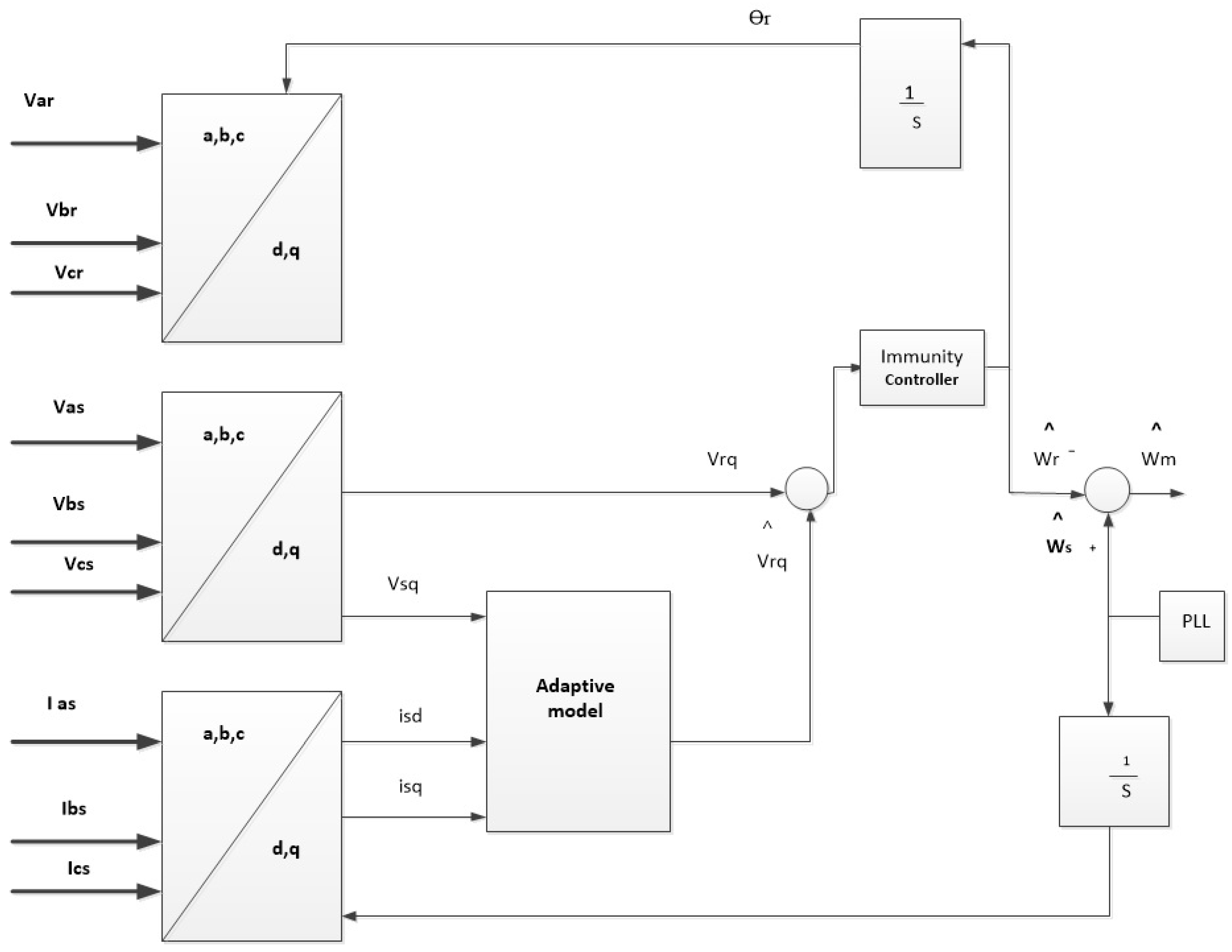
4.2. Rotor Speed Estimation of the DFIG
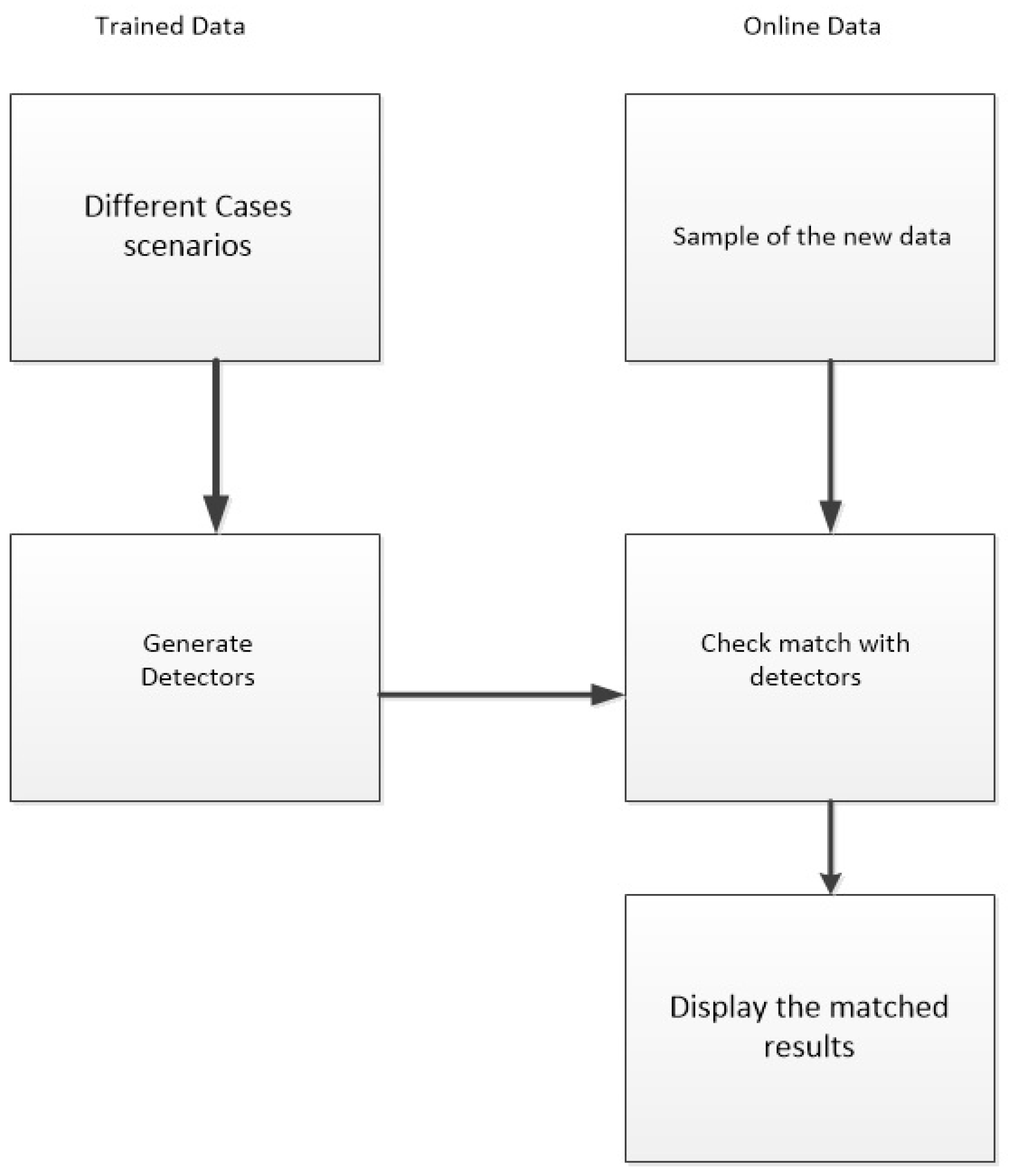
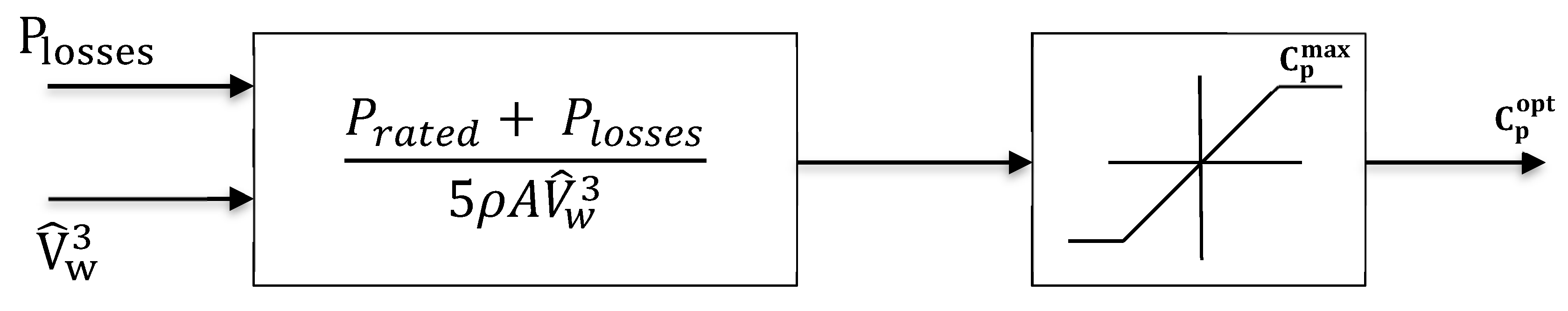
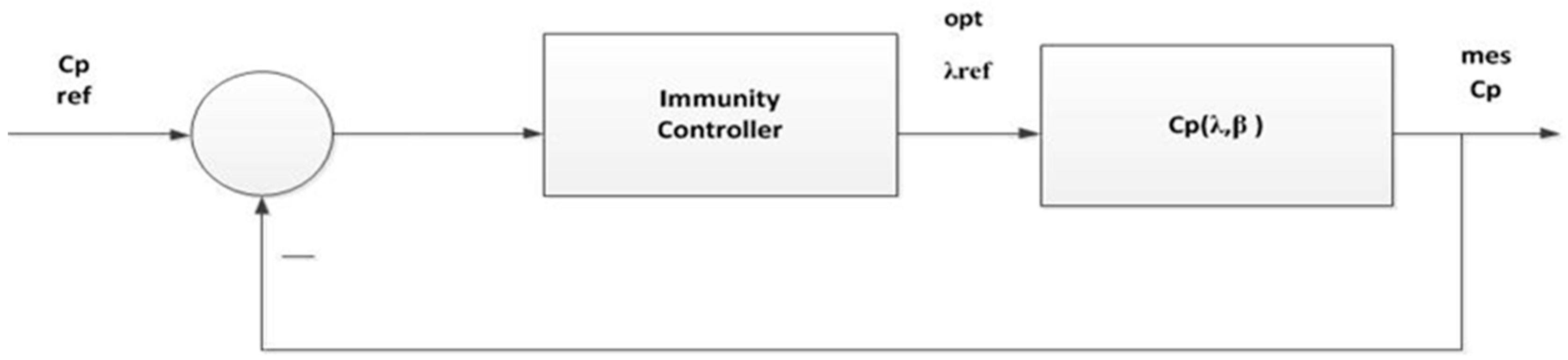
4.3. Sensorless MPPT Proposed Technique
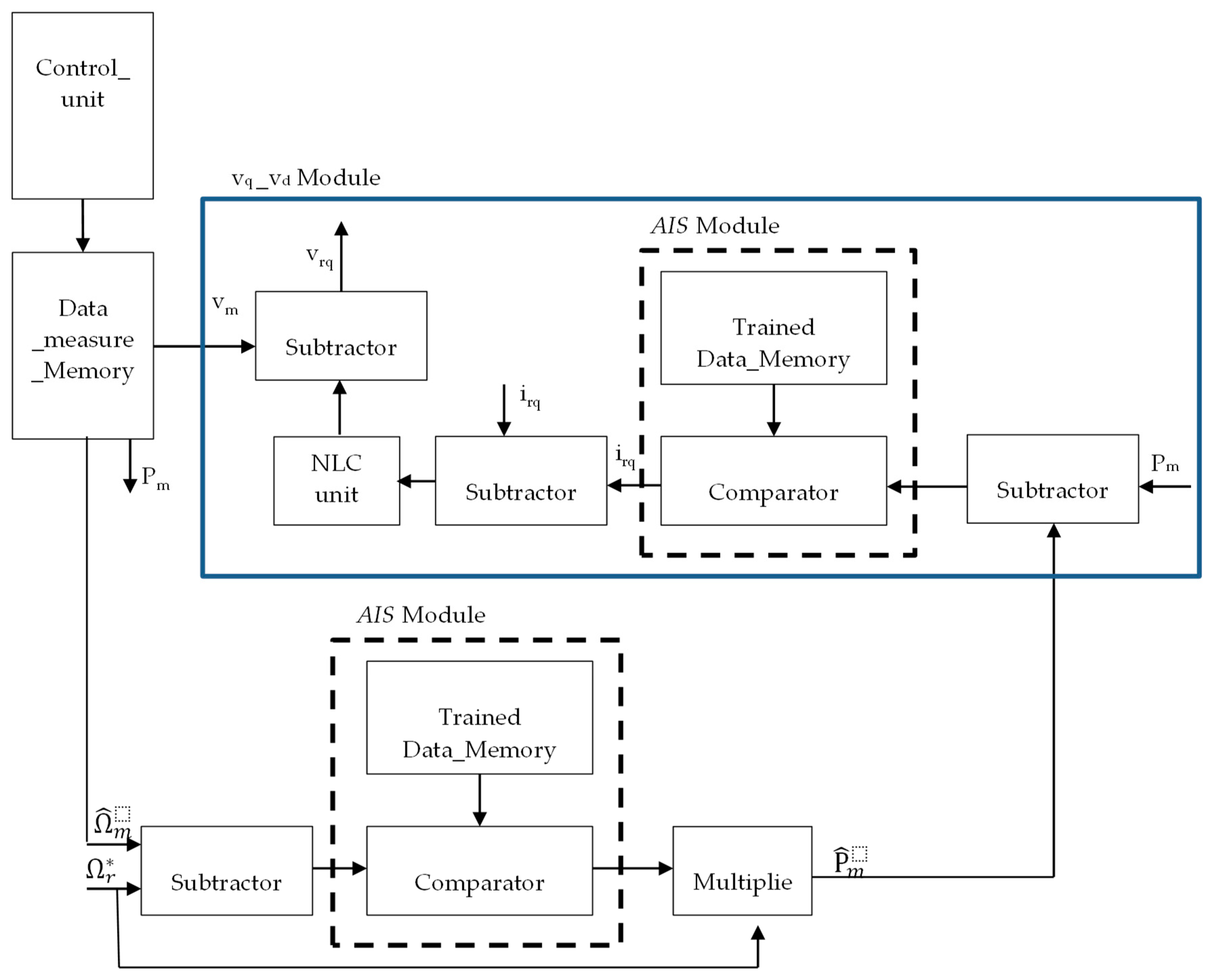
5. FPGA Based Implementation for MPPT Techniques
6. Simulation and Results
7. Conclusions
Author Contributions
Funding
Acknowledgments
Conflicts of Interest
Nomenclature
| Stator winding resistance | |
| Rotor winding resistance | |
| Flux linkage of the stator in the direct frame | |
| Flux linkage of the stator in the quadratic frame | |
| Rotational speed of the synchronous reference frame | |
| The rotor reference frame rotating | |
| Stator direct voltage | |
| Stator quadratic voltage | |
| Stator direct current | |
| Stator quadratic current | |
| Stator Winding Inductance | |
| Rotor Winding Inductance | |
| Mutual Inductance | |
| Direct rotor voltage | |
| Rotor voltage with respect to quadratic frame | |
| Direct rotor current | |
| Quadratic rotor current | |
| Flux linkage of the rotor in the direct frame | |
| Flux linkage of the rotor in the quadratic frame | |
| J | Moment of inertia |
| Cm | Mechanical torque |
| Ce | Electromagnetic torque |
| P | Number of pole pairs |
| vwm | Wind speed |
| Pm | Mechanical power generated by the turbine |
| ρ | Density of the air in kg/m3 |
| A | Area swept by blade in m2 |
| R | Radius of the blade in m |
| Cp | Power coefficient |
| Blade pitch angle | |
| Tip-speed-ratio | |
| Qs | Reactive power |
| Rotational speed of the wind turbine in rad/s. | |
| Reference rotational speed of DFIG in rad/s | |
| Optimal speed of the turbine | |
| g | Gearbox ratio |
| Friction coefficient | |
| Estimated mechanical power | |
| Reference electromagnetic torque | |
| Optimal Power coefficient | |
| Estimated DFIG rotor’s speed | |
| Power losses in the gearbox |
References
- Bañosa, R.; Manzano-Agugliarob, F.; Montoyab, F.G.; Gila, C.; Alcaydeb, A.; Gómezc, J. Optimization methods applied to renewable and sustainable energy; A review. Renew. Sustain. Energy Rev. 2011, 15, 1753–1766. [Google Scholar] [CrossRef]
- Yaramasu, V.; Dekka, A.; Durán, M.J.; Kouro, S.; Wum, B. PMSG-based wind energy conversion systems: Survey on power converters. IET Electr. Power Appl. 2017, 11, 956–968. [Google Scholar] [CrossRef]
- Gonçalves, P.F.C.; Cruz, G.M.A.; Mendes, A.M.S.; Abadi, M.B. Fault tolerant predictive power control for wind energy application. IET Electr. Power Appl. 2017, 11, 969–980. [Google Scholar] [CrossRef]
- Anaya-Lara, O. Wind Energy Generation: Modelling and Control; John Wiley and Sons: New York, NY, USA, 2009. [Google Scholar]
- Aho, J.; Buckspan, A.; Laks, J.; Fleming, P.; Jeong, Y.; Dunne, F.; Churchfield, M.; Pao, L.; Johnson, K. A tutorial of wind turbine control for supporting grid frequency through active power control. In Proceedings of the 2012 American Control Conference (ACC), Montreal, QC, Canada, 27–29 June 2012; pp. 27–29. [Google Scholar]
- Gonzralez, G.; Carranza, O. Maximum power point tracking with reduced mechanical stress applied to wind energy conversion systems. Appl. Energy 2010, 87, 2304–2312. [Google Scholar] [CrossRef]
- Hong-Hee, L.; Phan, Q.D.; Le, M.P.; Le, D.K.; Nguyen, H.N. A new fuzzy logic approach for control system of wind turbine with doubly fed induction generator. In Proceedings of the International Forum on Strategic Technology 2010, Ulsan, Korea, 13–15 October 2010. [Google Scholar]
- Lee, D.; Park, Y.G.; Park, J.B.; Roh, J.H. Very Short-Term Wind Power Ensemble Forecasting without Numerical Weather Prediction through the Predictor Design. J. Electr. Eng. Technol. 2017, 12, 2177–2186. [Google Scholar]
- Renewable 2017. Available online: https://www.iea.org/publications/renewables2017/ (accessed on 30 June 2018).
- Xu, Z.; Hu, Q.; Ehsani, M. Estimation of effective wind speed for fixed speed wind turbines based on frequency domain data fusion. IEEE Trans. Sustain. Energy 2012, 3, 57–64. [Google Scholar] [CrossRef]
- Hussein, M.M.; Senjyu, T.; Orabi, M.; Hamada, M.M. Control of a Stand-Alone Variable Speed Wind Energy Supply System. Appl. Sci. 2013, 3, 437–456. [Google Scholar] [CrossRef]
- Meyer, D.G.; Srinivasan, S.; Semrau, G. Dynamic wind estimation based control for small wind turbines. Renew. Energy 2013, 50, 259–267. [Google Scholar] [CrossRef]
- Munteanu, I.; Bratcu, A.I.; Cutululis, N.A.; Ceanga, E. Optimal Control of Wind Energy Systems towards a Global Approach, 1st ed.; Springer: London, UK, 2008. [Google Scholar]
- Munteanu, I.; Besan, G. Control-based strategy for effective wind speed estimation in wind turbines. In Proceedings of the 19th World Congress on International Federation of Automatic Control, Cape Town, South Africa, 24–29 August 2014; Volume 47, pp. 6776–6781. [Google Scholar] [CrossRef]
- Rajendran, S.; Jena, D. Variable speed wind turbine for maximum power capture using adaptive fuzzy integral sliding mode control. J. Mod. Power Syst. Clean Energy 2014, 2, 114–125. [Google Scholar] [CrossRef]
- Wang, Q.; Chang, L. An intelligent maximum power extraction algorithm for inverter-based variable speed wind turbine systems. IEEE Trans Power Electron. 2004, 19, 1242–1249. [Google Scholar] [CrossRef]
- Kusiak, A.; Zheng, H.; Song, Z. Short-term prediction of wind farm power: a data mining approach. IEEE Trans. Energy Convers. 2009, 24, 125–135. [Google Scholar] [CrossRef]
- Li, S.; Wunsch, D.C.; O’Hair, E.A.; Giesselmann, M.G. Using neural networks to estimate wind turbine power generation. IEEE Trans. Energy Convers. 2001, 16, 267–282. [Google Scholar]
- Kitajima, T.; Yasuno, T. Output Prediction of Wind Power Generation System Using Complex-valued Neural Network. In Proceedings of the SICE Annual Conference 2010, Taipei, Taiwan, 18–21 August 2010; pp. 3610–3613. [Google Scholar]
- Alberto, L.; Cuatzin, H.G. Fuzzy Proportional Integral Control for a 1.5 MW Wind Turbine. Rev. Univ. Telecomun. Inf. Control 2012, 1, 5–6. [Google Scholar]
- Ahmed, O.A.; Ahmed, A.A. Control of Wind Turbine for Variable Speed Based on Fuzzy-PID Controller. SUST J. Eng. Comput. Sci. (JECS) 2017, 18, 40–51. [Google Scholar]
- Rahman, M.M.; A-Rahim, A.H.M. An efficient wind speed sensor-less MPPT controller using adaptive neuro-fuzzy inference system. In Proceedings of the 2015 International Conference on Advances in Electrical Engineering (ICAEE), Dhaka, Bangladesh, 17–19 December 2015; pp. 230–233. [Google Scholar]
- Mohandes, M.; Rehman, S.; Rahman, S.M. Estimation of wind speed profile using adaptive neuro-fuzzy inference system (ANFIS). Appl. Energy 2011, 88, 402–432. [Google Scholar] [CrossRef]
- Tiwari, A.; Shewale, A.; Lokhande, N. Comparison of various Wind Turbine Generators. Multidiscip. J. Res. Eng. Technol. 2011, 1, 129–135. [Google Scholar]
- Pena, R.; Clare, J.C.; Asher, G.M. Doubly fed induction generator using back-to-back PWM converters and its application to variablespeed wind-energy generation. IEE Proc.-Electr. Appl. 1996, 143, 231–241. [Google Scholar] [CrossRef]
- Ekanayake, J.B.; Holdsworth, L.; Wu, X.G.; Jenkins, N. Dynamic modeling of doubly fed induction generator wind turbine. IEEE Trans. Power Syst. 2003, 18, 803–809. [Google Scholar] [CrossRef]
- Vas, P. Sensorless Vector and Direct Torque Control; Oxford University Press: New York, NY, USA, 1998. [Google Scholar]
- Miller, N.W.; Sanchez-Gasca, J.J.; Price, W.W.; Delmerico, R.W. Dynamic modeling of GE 1.5 and 3.6 MW wind turbine-generators for stability simulations. In Proceedings of the 2003 IEEE Power Engineering Society General Meeting (IEEE Cat. No.03CH37491), Toronto, ON, Canada, 13–17 July 2003; pp. 1977–1983. [Google Scholar]
- Abd El-Hamid, M.A.; El-Amary, N.H.; Mansour, M.M. Micro Grid Studies due to Fault Occurance using Immunity Technique. In Proceedings of the 11th IASTED European Conference on Power and Energy Systems, Napoli, Italy, 25–27 June 2012; pp. 20–25. [Google Scholar]
- Wang, X.; Gao, X.; Ovaska, S. Artificial Immune Optimization Methods and Applications—A Survey. In Proceedings of the 2004 IEEE International Conference on Systems, Man and Cybernetics (IEEE Cat. No.04CH37583), The Hague, Holland, 10–13 October 2004; pp. 3415–3420. [Google Scholar]
- Abd El-Hamid, M.A. Controlling Robotic Arm Assisted in Knee Surgery Utilizing Artificial Immunity Technique. In Proceedings of the UKSIM 2013 the IEEE international conference on modeling and simulation, Cambridge, UK, 10–12 April 2013. [Google Scholar]
- Abd El Hamied, M.A. Tracking and Controlling Maximum Power Point Utilizing Artificial Intelligent system. In Proceedings of the 2015 IEEE International Conference on Smart City/SocialCom/SustainCom (SmartCity), Chengdu, China, 19–21 December 2015. [Google Scholar]
- Abd El-Hamid, M.A.; El-Amary, N.H. Voltage Instability Prediction Using Artificial Immunity Technique. Int. J. Sci. Eng. Res. 2013, 4, 559–593. [Google Scholar]
- Dadone, A.; Dambrosio, L. Estimator based adaptive fuzzy logic control technique for a wind turbine–generator system. Energy Convers. Manag. 2003, 44, 135–153. [Google Scholar] [CrossRef]
- Angeline, K.R.; Yadlapati, S.K.B. Modelling and Simulation of ANFIS Controlled Doubly FED Induction Generator Based Wind Energy System for Performance Enhancement. Int. Sci. Press IJCTA 2017, 10, 61–73. [Google Scholar]
- Montoya, F.G.; Manzano-Agugliaro, F.; Lropez-Mrarquez, S.; Hernrandez-Escobedo, Q.; Gil, C. Wind turbine selection for wind farm layout using multiobjective evolutionary algorithms. Expert Syst. Appl. 2014, 41, 6585–6595. [Google Scholar] [CrossRef]
- Barakati, S.M.; Kazerani, M.; Aplevich, J.D. Maximum power tracking control for a wind turbine system including a matrix converter. IEEE Trans. Energy Convers. 2009, 24, 705–713. [Google Scholar] [CrossRef]
- Hong, C.-M.; Ou, T.-C.; Lu, K.-H. Development of intelligent MPPT (maximum power point tracking) control for a grid-connected hybrid power generation system. Energy 2013, 50, 270–279. [Google Scholar] [CrossRef]
- Simoes, M.G.; Bose, B.K.; Spiegel, R.J. Design and performance evaluation of a fuzzy-logic-based variable-speed wind generation system. IEEE Trans. Ind. Appl. 1997, 33, 956–965. [Google Scholar] [CrossRef]
- Belmokhtar, K.; Doumbia, M.L.; Agbossou, K. Novel fuzzy logic based sensorless maximum power point tracking strategy for wind turbine systems driven DFIG (doubly-fed induction generator). Energy 2014, 76, 679–693. [Google Scholar] [CrossRef]
- Cardenas, R.; Pena, R. Sensorless vector control of induction machines for variable-speed wind energy applications. IEEE Trans. Energy Convers. 2004, 19, 196–205. [Google Scholar] [CrossRef]
- Kumar, A.; Satwase, A.; Mishra, R. Transient Behavior of Doubly Fed Induction Generator Using Simulink Model in Wind Energy Conversion System. Int J. Innov. Res. Sci. Eng. Technol. 2015, 4, 450–454. [Google Scholar]
- Banakar, H.; Luo, C.; Ooi, B.T. Steady-state stability analysis of doubly-fed induction generators under decoupled PQ control. IEE Proc.-Electr. Power Appl. 2006, 153, 300–306. [Google Scholar] [CrossRef]
- Marques, G.D.; Sousa, D.M. New Sensorless Rotor Position Estimator of a DFIG Based on Torque Calculations Stability Study. IEEE Trans. Energy Convers. 2012, 27, 196–202. [Google Scholar] [CrossRef]
- Nelson, R.H.; Lipo, T.A.; Krause, P.C. Stability analysis of a symmetrical induction machine. IEEE Trans. Power Appar. Syst. 1969, PAS-88, 1710–1717. [Google Scholar] [CrossRef]
- Amin, I.K.; Uddin, M.N. Nonlinear Control Operation of DFIG based WECS with Stability Analysis. In Proceedings of the 2017 IEEE Industry Applications Society Annual Meeting, Cincinnati, OH, USA, 1–5 October 2017; pp. 1–8. [Google Scholar]
- Cheikh, R.; Belmili, H. Nonlinear Control of a Grid-Connected Double Fed Induction Generator Based Vertical Axis Wind Turbine: A Residential Application. Int. J. Electr. Energy 2016, 4, 4. [Google Scholar]
- Boudjema, Z.; Meroufel, A.; Djerriri, Y. Nonlinear control of a doubly fed induction generator for wind energy conversion. Carpath. J. Electron. Comput. Eng. 2013, 6, 28–35. [Google Scholar]
- Abad, G.; Lopez, J.; Rodriguez, M.; Marroyo, L.; Iwanski, G. Doubly Fed Induction Machine: Modeling and Control for Wind Energy Generation, 1st ed.; John Wiley and Sons, Inc.: Hobokes, NJ, USA, 2011. [Google Scholar]
- Hansen, A.D.; Srensen, P.; Iov, F.; Blaabjerg, F. Control of variable speed wind turbines with doubly-fed induction generators. Wind Eng. 2004, 28, 411–434. [Google Scholar] [CrossRef]
- Alrifai, M.; Mohamed, Z.; Rayan, M. Feedback Linearization Controller for a Wind Energy Power System. In Proceedings of the 24th Mediterranean Conference on Control and Automation, Athens, Greece, 21–24 June 2016. [Google Scholar]
- Chen, J.; Jiang, L.; Yao, W.; Wu, Q.H. Perturbation estimation based nonlinear adaptive control of a full-rated converter wind turbine for fault ride-through capability enhancement. IEEE Trans. Power Syst. 2014, 29, 2733–2743. [Google Scholar]
- Xiang, D.; Ran, L.; Tavner, P.J.; Yang, S. Control of a doubly fed induction generator in a wind turbine during grid fault ride-through. IEEE Trans. Energy Convers. 2006, 21, 652–662. [Google Scholar] [CrossRef]
- Lopez, J.; Sanchis, P.; Roboam, X.; Marroyo, L. Dynamic behavior of the doubly fed induction generator during three-phase voltage dips. IEEE Trans. Energy Convers. 2007, 22, 709–717. [Google Scholar] [CrossRef]
- Khemiri, N.; Khedher, A.; Mimouni, M.F. Wind Energy Conversion System using DFIG Controlled by Backstep-ping and Sliding Mode. Int. J. Renew. Energy Res. 2012, 2, 421–430. [Google Scholar]
- Ouari, K.; Rekioua, T.; Ouhrouche, M.A. Non Linear Predictive Controller for Wind Energy Conversion System. In Proceedings of the International Renewable Energy Congress IREC, Sousse, Tunisia, 5–7 November 2010; pp. 220–226. [Google Scholar]
- Isidori, A.; Krener, A.j.; Gori-Giorgi, C.; Monaco, S. Non linear decoupling via feedback: A differential geometric approach. IEEE Trans. Autom. Control 1981, 26, 331–345. [Google Scholar] [CrossRef]
- Wei, Q.; Wei, Z.; Aller, J.M.; Harley, R.G. Wind speed estimation based sensorless output maximization control for a wind turbine driving a DFIG. IEEE Trans. Power Electron. 2008, 23, 1156–1169. [Google Scholar]
- Ltifi, A.; Ghariani, M.; Neji, R. Comparison of Two Techniques for Control Nonlinear Systems: The PI Regulator and Sliding Mode Control. In Proceedings of the International Conference on Control, Engineering Technology, Sousse, Tunisia, 22–25 March 2014. [Google Scholar]
- Isidori, A. Nonlinear Control Systems, 3rd ed.; Springer: London, UK, 1995; ISBN 978-3-540-19916-8. [Google Scholar]
- Huimin, L.; Yujie, L.; Min, C.; Hyoungseop, K.; Seiichi, S. Brain Intelligence: Go beyond Artificial Intelligence. Mob. Netw. Appl. 2018, 23, 368–375. [Google Scholar] [CrossRef]
- Chekired, F.; Mellit, A.; Kalogirou, S.A.; Larbes, C. Intelligent maximum power point trackers for photovoltaic applications using FPGA chip: A comparative study. Sol. Energy 2014, 101, 83–99. [Google Scholar] [CrossRef]
- Adel, M.; Kalogirou, S.A. MPPT-based artificial intelligence techniques for photovoltaic systems and its implementation into field programmable gate array chips: Review of current status and future perspectives. Energy Elsevier 2014, 70, 1–21. [Google Scholar] [CrossRef]
- Dileep, G.; Singh, S.N. Maximum power point tracking of solar photovoltaic system using modified perturbation and observation method. Renew. Sustain. Energy Rev. 2015, 50, 109–129. [Google Scholar] [CrossRef]
- Karim, K.; Cherif, L.; Naeem, R.; Moussaab, B.; Zine elabadine, D. Bat algorithm based maximum power point tracking for photovoltaic system under partial shading conditions. Sol. Energy 2017, 158, 490–503. [Google Scholar]
- Accetta, A.; Di Piazza, M.C.; Tona, G.L.; Luna, M.; Pucci, M. A high-performance FPGA-based virtual anemometer for MPPT of wind energy conversion systems. In Proceedings of the IEEE 26th International Symposium on Industrial Electronics (ISIE), Edinburgh, UK, 19–21 June 2017; pp. 926–933. [Google Scholar]
- Youssef, A.; ElTelbany, M.; Zekry, A. Reconfigurable generic FPGA implementation of fuzzy logic controller for MPPT of PV systems. Renew. Sustain. Energy Rev. 2018, 82, 1313–1319. [Google Scholar] [CrossRef]
- Mattioni, M.; Monaco, S.; Normand-Cyrot, D. Sampled-data reduction of nonlinear input-delayed dynamics. IEEE Control Syst. Lett. (L-CSS) 2017, 1, 116–121. [Google Scholar] [CrossRef]
- Monaco, S.; Normand-Cyrot, D.; Mattioni, M. Sampled-data stabilization of nonlinear dynamics with input delays through Immersion and Invariance. IEEE Trans. Autom. Control 2017, 62, 2561–2567. [Google Scholar] [CrossRef]


| The DFIG Data 0.2 mH of a Typical 3.7 kW Generator | |
|---|---|
| Frame/power | 3.7 kW |
| Efficiency at rated speed | approximately 97–97.5 |
| Voltage | 690 V |
| Locked rotor voltage | approximately 1000 V |
| Operation speed range | 1000–2000 rpm |
| Power factor | p.f. 0.90 cap –1.0 |
| Rotor Resistance | 1 kW |
| Rotor Inductance | |
| Stator Resistance | 0.5 kW |
| Stator Inductance | 0.001 mH |
| Mutual inductance | Msr = 0.078 H |
| Number of poles | 4 |
| Inertia moment | J = 0.3125 Nms2 |
| Execution Time | |
|---|---|
| Fuzzy MPPT controller | 14.11 s |
| Conventional Method | 10.333 s |
| AIS MPPT | 11.66 s |
| AISE | 13.22 s |
| ASO | 2.72 s |
| Total AI time | ~23 s |
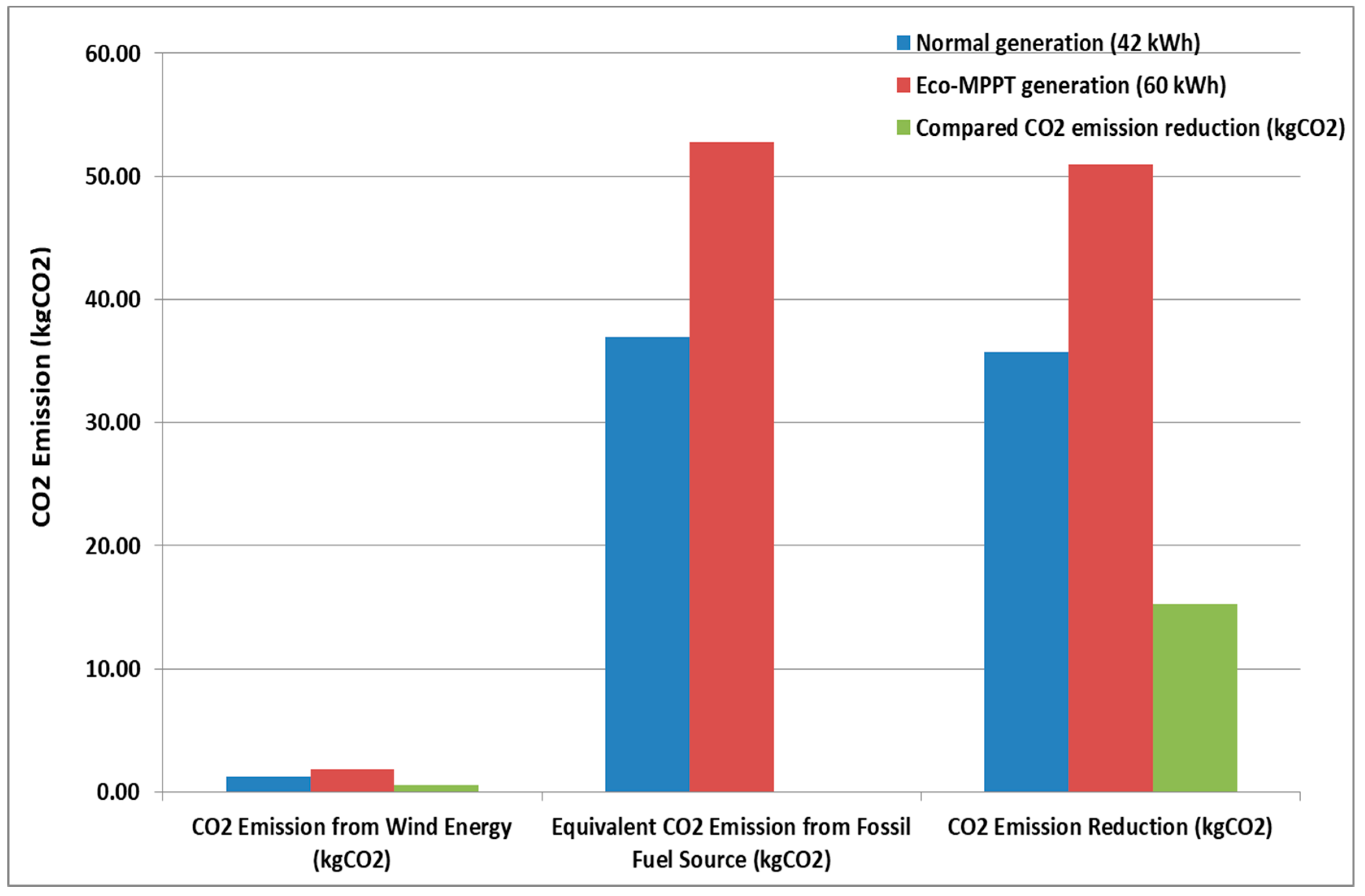
| CO2 Emission from Wind Energy (kgCO2) | CO2 Emission from Fossil Fuel Source (kgCO2) | CO2 Emission Reduction (kgCO2) | |
|---|---|---|---|
| Normal generation (42 kWh) | 1.26 | 36.96 | 35.7 |
| Eco-MPPT generation (60 kWh) | 1.8 | 52.8 | 51 |
| Compared CO2 emission reduction (kgCO2) | 0.54 | 15.3 |
© 2018 by the authors. Licensee MDPI, Basel, Switzerland. This article is an open access article distributed under the terms and conditions of the Creative Commons Attribution (CC BY) license (http://creativecommons.org/licenses/by/4.0/).
Share and Cite
Hassan, M.; Balbaa, A.; Issa, H.H.; El-Amary, N.H. Asymptotic Output Tracked Artificial Immunity Controller for Eco-Maximum Power Point Tracking of Wind Turbine Driven by Doubly Fed Induction Generator. Energies 2018, 11, 2632. https://doi.org/10.3390/en11102632
Hassan M, Balbaa A, Issa HH, El-Amary NH. Asymptotic Output Tracked Artificial Immunity Controller for Eco-Maximum Power Point Tracking of Wind Turbine Driven by Doubly Fed Induction Generator. Energies. 2018; 11(10):2632. https://doi.org/10.3390/en11102632
Chicago/Turabian StyleHassan, Marwa, Alsnosy Balbaa, Hanady H. Issa, and Noha H. El-Amary. 2018. "Asymptotic Output Tracked Artificial Immunity Controller for Eco-Maximum Power Point Tracking of Wind Turbine Driven by Doubly Fed Induction Generator" Energies 11, no. 10: 2632. https://doi.org/10.3390/en11102632
APA StyleHassan, M., Balbaa, A., Issa, H. H., & El-Amary, N. H. (2018). Asymptotic Output Tracked Artificial Immunity Controller for Eco-Maximum Power Point Tracking of Wind Turbine Driven by Doubly Fed Induction Generator. Energies, 11(10), 2632. https://doi.org/10.3390/en11102632