Article

Investigation of Thermal Stress of Cement Sheath for Geothermal Wells during Fracturing

1
School of Petroleum and Natural Gas Engineering, Chongqing University of Science and Technology, Chongqing 401331, China
2
State Key Laboratory of Oil and Gas Reservoir Geology and Exploitation, Southwest Petroleum University, Chengdu 610500, China
3
State Key Laboratory of Geomechanics and Geotechnical Engineering, Institute of Rock and Soil Mechanics, Chinese Academy of Sciences (CAS), Wuhan 430071, China
*
Author to whom correspondence should be addressed.
Energies 2018, 11(10), 2581; https://doi.org/10.3390/en11102581
Submission received: 29 August 2018 / Revised: 21 September 2018 / Accepted: 24 September 2018 / Published: 27 September 2018
(This article belongs to the Special Issue Geothermal Energy: Utilization and Technology 2018)

Abstract

:
Geothermal energy development has increasingly been studied in recently decades because of its renewable and sustainable features. It can be divided into two categories: traditional geothermal (hydrothermal) systems and enhanced geothermal systems (EGS) based on the type of exploitation. The hot dry rock (HDR) in the EGS incorporates about 80% of all thermal energy, and its value is about 100–1000 times that of fossil energy. It is pivotal for geothermal wells to improve the flow conductivity of the HDR mass, enhance the communication area of natural fractures, and constitute the fracture network between injection and production wells by hydraulic treatments. While the wellbore temperature significantly decreases because of fracturing, fluid injection will induce additional thermal stresses in the cement sheath, which will aggravate its failure. Considering the radial nonuniform temperature change, this paper proposes a new thermal stress model for a casing-cement sheath-formation combined system for geothermal wells during fracturing based on elastic mechanics and thermodynamics theory. This model is solved by the Gaussian main elimination method. Based on the analytical model, the thermal stresses of cement sheath have been analyzed. The effects of the main influencing parameters on thermal stresses have also been investigated. Results show that the radial and axial tensile thermal stresses are both obviously larger than tangential tensile thermal stress. The maximum radial and axial thermal stresses always occur at the casing interface while the location of the maximum tangential thermal stress varies. Generally, thermal stresses are more likely to induce radial and axial micro cracks in the cement sheath, and the cement sheath will fail more easily at the casing interface in fracturing geothermal wells. For integrity protection of the cement sheath, a proper decrease of casing wall thickness, casing linear thermal expansion coefficient, cement sheath elasticity modulus, and an increase of the fracturing fluid temperature has been suggested.

1. Introduction

Geothermal energy is a renewable and sustainable energy and features weather independence, stable, operationally reliable, and environmentally friendly characteristics. It has been extensively studied to mitigate global warming, reduce air pollution, and meet the needs of global energy consumption [1]. In recent years, many countries have increased the exploration and development of geothermal energy due to abundant resources and great development potential [2,3,4,5,6,7,8]. Geothermal play systems have been divided into three different temperatures (or enthalpy) play types: low-temperature, moderate-temperature, and high-temperature mainly based on temperature and thermodynamic properties [9,10,11]. Geothermal systems also can be divided into two categories: traditional geothermal (hydrothermal) systems and enhanced geothermal systems (EGS) based on the type of exploitation [12]. Compared to conventional geothermal energy developments, EGS have the advantage of accessing more abundant heat by creating artificial fractures in the hot rocks and then injecting fluid into them [12]. The hot dry rock (HDR) in the EGS covers about 80% of all thermal energy, and its value is about 100–1000 times that of fossil energy [13,14]. Most HDR is buried in the range of 3 to 8 km underground with high confining pressures and high temperatures (more than 200 °C). It is pivotal for geothermal wells to improve the flow conductivity of the HDR mass, enhance the communication area of natural fractures, and constitute the fracture network between injection and production wells by hydraulic treatments [14]. The communication area of fractures is defined as the total area of connected fractures after fracturing operations, including the main hydraulic fractures and its connected natural fractures and the bedding plane [15]. For obtaining larger communication areas of fractures, high pump pressure fluid with continuous large displacement is usually injected into the well during fracturing. Consequently, to ensure the wellbore maintains mechanical and hydraulic integrity during fracturing and long-term production, the open hole for geothermal wells is usually cemented with a steel casing. However, laboratory investigations and field practice have both shown that the cement sheath is likely to fail at some stage in downhole operations due to additional stresses within the cement sheath from variations of wellbore temperature and pressure [16,17,18]. For fracturing wells, wellbore temperature may suffer a very significant decrease (up to −70 °C) [19] because of high displacement and pump pressure during fracturing fluid injection, and the casing and cement sheath very likely fail in this case. This will not only affect the communication of fracture nets but also bring security risks to the geothermal exploitation system. The integrity of the wellbore in the process of fracturing resulting from temperature change has been studied by a number scholars. Teodoriu and Falcone [20] contrasted the differences in well completion of an oil–gas well and a geothermal well and discussed the requirements of geothermal well completion. They pointed out that special attention needs to be given to thermal stresses induced by temperature variations in the casing string of a geothermal well. Zhou et al. [21] carried out an experimental study on hydraulic fracturing of granite under thermal shock. The results showed that the cooling effect of the fracturing fluid for a high-temperature borehole can lead to the thermal shock phenomenon and cause tensile stress near the borehole surface. They were concerned about the damage of the casing and the fracturing of rock caused by the temperature change, but less attention was paid to the integrity of the cement sheath from changes in temperature during fracturing. Thus, studying the integrity of the cement sheath during the fracturing process in response to temperature change is very important for a geothermal well’s long-term, safe, and efficient production.
Up to now, available mechanical models of cement sheath coupling temperatures and pressures have mainly been developed for high pressure and high temperature (HPHT) wells and thermal wells. Thiercelin et al. [22] first established a cement sheath model and verified that thermo-elastic properties of the casing, cement, and formation have an obvious effect on cement failure. Li et al. [23] deduced the theoretical solution of thermal stress for casing-cement-formation coupling systems, but only analyzed the casing thermal stress for thermal wells. Li et al. [24] established a mechanical model coupling effect of temperature and pressure and researched the behavior of the cement sheath in non-uniform in-situ stress fields. Teodoriu et al. [25] proposed a casing-cement-formation interaction analytical model considering radial uniform temperature change. Bois et al. [26] also developed a mechanical model of cement sheath and simulated its failure mode from casing deformation owing to wellbore temperature change. Haider et al. [27] developed a composite axisymmetric multi-cylinder wellbore model and investigations showed that the wellbore temperature decrease can develop tensile radial stresses in the cement sheath. Bui et al. [28] presented a mathematical model for predicting the failure of the cement sheath in an anisotropic stress field, and thermal stress was also considered. Xu et al. [29] proposed an analytical model of the cement sheath and studied the wellhead casing pressure on cement sheath stress for HPHT gas wells with consideration to wellbore temperature change. To some extent all the models above could be used to calculate the thermal stress in cement sheath, however, because of the complexity of wellbore geometry and radial thermal conduction, uniform temperature change from the inner casing wall to outer formation wall has been supposed. Consequently, the present models cannot produce an accurate thermal stress measurement for a cement sheath which directly influences the judgment of its failure.
In this paper, the thermal stress model of a casing-cement sheath-formation combined system for geothermal wells during fracturing is proposed based on the elastic mechanics and thermodynamics theory. The radial nonuniform temperature change in the combined system has been considered, and both the radial stress and radial displacement at the casing-cement sheath interface and the cement sheath-formation interface have been supposed to be continuous. Based on the analytical model, the thermal stress distribution of cement sheath was calculated during fracturing fluid injection. In addition, the effects of relevant parameters on cement sheath thermal stress distribution were studied, whose results can be of great significance for integrity protection of the cement sheath for geothermal wells during fracturing.

2. Thermal Stress Model Development and Solution

2.1. Basic Assumptions

To propose the thermal stress model, some basic assumptions were made as follows:
  • The casing, cement sheath, and formation are all considered as homogeneous isotropic materials;
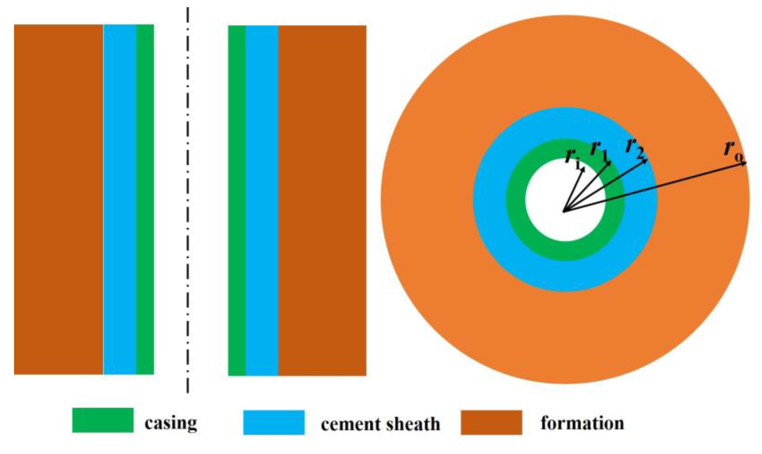
  • The casing-cement sheath-formation combined system is completely cemented and deemed as a composed thick-wall cylinder;
  • The radial stress and radial displacement at the casing-cement sheath interface and the cement sheath-formation interface are both continuous;
  • The nonuniform temperature varies along the radial direction of the combined system except for the casing in consideration of its thin wall and well heat conduction performance;
  • The temperature at the inner wall of the casing is equal to wellbore temperature, and that at the outer wall of the combined system maintains at formation temperature during fracturing.
  • The combined cylinder is deemed as an axisymmetric problem.
The thermal stress calculation model of casing-cement sheath-formation combined system is shown in Figure 1.

2.2. Modelling

According to the elastic mechanics and thermodynamics theory [30], the stress–strain relationship for a thick wall cylinder is given as follows:
{ ε r = 1 E [ σ r μ ( σ θ + σ z ) ] + α T ( r ) ε θ = 1 E [ σ θ μ ( σ z + σ r ) ] + α T ( r ) ε z = 1 E [ σ z μ ( σ r + σ θ ) ] + α T ( r )
Considering the geometrical relationship ε r = d u / d r and ε θ = u / r , we can obtain the equilibrium equation:
d 2 u d r 2 + 1 r d u d r u r 2 = α ( 1 + μ ) d T ( r ) ( 1 μ ) d r
In Equations (1) and (2), the temperature change value T(r) after fracturing fluid injection at a radius of r in the combined cylinder can be calculated from:
T ( r ) = T a ( r ) T b ( r )
Solving Equation (2), we can get the general solutions of thermal displacement and thermal stresses for a thick wall cylinder as follows:
{ u = 1 + μ 1 μ α r a r T ( r ) r d r + C 1 r + C 2 r σ r = α E 1 μ 1 r 2 a r T ( r ) r d r + E 1 + μ ( C 1 1 2 μ C 2 r 2 ) σ θ = α E 1 μ 1 r 2 a r T ( r ) r d r α E T b ( r ) 1 μ + E 1 + μ ( C 1 1 2 μ + C 2 r 2 ) σ z = α E T ( r ) 1 μ + 2 μ E C 1 ( 1 + μ ) ( 1 2 μ )
We consider temperature varies constantly in the casing and logarithmically in cement and formation. Before fracturing fluid injection, if wellbore temperature is Ti and formation temperature is Te, the temperature distribution along the radial direction of the combined cylinder can be obtained.
T b ( r ) = { T i ( r i r r 1 ) T i + ( T e T i ) ln ( r / r 1 ) ln ( r o / r 1 ) ( r 1 r r o )
Similarly, after injecting the fracturing fluid, if wellbore temperature decreased to Tt and formation temperature is still Te, the temperature distribution along the radial direction of the combined cylinder can also be obtained.
T a ( r ) = { T t ( r i r r 1 ) T t + ( T e T t ) ln ( r / r 1 ) ln ( r o / r 1 ) ( r 1 r r o )
According to Equation (3) and combing Equations (5) and (6), the temperature change value for the combined cylinder after fracturing fluid injection is:
T ( r ) = { T t T i ( r i r r 1 ) T t T i + ( T i T t ) ln ( r / r 1 ) ln ( r o / r 1 ) ( r 1 r r o )
The integral expression a r T ( r ) r d r in Equation (4), can be expressed as:
a r T ( r ) r d r = { 1 2 ( T t T i ) ( r 2 r i 2 ) ( r i r r 1 ) 1 2 ( T t T i ) ( r 2 r 1 2 ) + ( T i T t ) 2 ln ( r o / r 1 ) [ r 2 ln ( r r 1 ) r 2 2 + r 1 2 2 ] ( r 1 r r o )
Then submitting Equations (5), (7), and (8) into Equation (4), the thermal displacement and thermal stresses for the combined cylinder can be calculated.
For the casing (rirr1):
{ u s = 1 + μ s 1 μ s α s r 1 2 ( T t T i ) ( r 2 r i 2 ) + C 1 s r + C 2 s r σ r s = α s E s 1 μ s 1 r 2 1 2 ( T t T i ) ( r 2 r i 2 ) + E s 1 + μ s ( C 1 s 1 2 μ s C 2 s r 2 ) σ θ s = α s E s 1 μ s 1 r 2 1 2 ( T t T i ) ( r 2 r i 2 ) α s E s ( T t T i ) 1 μ s + E s 1 + μ s ( C 1 s 1 2 μ s + C 2 s r 2 ) σ z s = α s E s ( T t T i ) 1 μ s + 2 μ s E s C 1 s ( 1 + μ s ) ( 1 2 μ s )
For the cement sheath (r1rr2):
{ u c = 1 + μ c 1 μ c α c r { T t T i 2 ( r 2 r 1 2 ) + ( T i T t ) 2 ln ( r o / r 1 ) [ r 2 ln ( r r 1 ) r 2 2 + r 1 2 2 ] } + C 1 c r + C 2 c r σ r c = α c E c 1 μ c 1 r 2 { T t T i 2 ( r 2 r 1 2 ) + ( T i - T t ) 2 ln ( r o / r 1 ) [ r 1 ln ( r r 1 ) r 2 2 + r 1 2 2 ] } + E c 1 + μ c ( C 1 c 1 2 μ c C 2 c r 2 ) σ θ c = α c E c 1 μ c 1 r 2 { T t T i 2 ( r 2 r 1 2 ) + ( T i T t ) 2 ln ( r o / r 1 ) [ r 2 ln ( r r 1 ) r 2 2 + r 1 2 2 ] }        α c E c 1 μ c [ T t T i + ( T i T t ) ln ( r / r 1 ) ln ( r o / r 1 ) ] + E c 1 + μ c ( C 1 c 1 2 μ c + C 2 c r 2 ) σ z c = α c E c 1 μ c [ T t T i + ( T i T t ) ln ( r / r 1 ) ln ( r o / r 1 ) ] + 2 μ c E c C 1 c ( 1 + μ c ) ( 1 2 μ c )
For the formation (r2rro):
{ u f = 1 + μ f 1 μ f α f r { T t T i 2 ( r 2 r 1 2 ) + ( T i T t ) 2 ln ( r o / r 1 ) [ r 2 ln ( r / r 1 ) r 2 2 + r 1 2 2 ] } + C 1 f r + C 2 f r σ r f = α f E f 1 μ f 1 r 2 { T t T i 2 ( r 2 r 1 2 ) + ( T i T t ) 2 ln ( r o / r 1 ) [ r 2 ln ( r / r 1 ) r 2 2 + r 1 2 2 ] } + E f 1 + μ f ( C 1 f 1 2 μ f C 2 f r 2 ) σ θ f = α f E f 1 μ f 1 r 2 { T t T i 2 ( r 2 r 1 2 ) + ( T i T t ) 2 ln ( r o / r 1 ) [ r 2 ln ( r / r 1 ) r 2 2 + r 1 2 2 ] }        α f E f 1 μ f [ T t T i + ( T i T t ) ln ( r / r 1 ) ln ( r o / r 1 ) ] + E f 1 + μ f ( C 1 f 1 2 μ f + C 2 f r 2 ) σ z f = α f E f 1 μ f [ T t T i + ( T i T t ) ln ( r / r 1 ) ln ( r o / r 1 ) ] + 2 μ f E f C 1 f ( 1 + μ f ) ( 1 2 μ f )

2.3. Model Solution

To get the thermal displacement and thermal stresses distribution in the casing, cement sheath, and formation, the key problem is to solve the six undetermined coefficients of C1s, C2s, C1c, C2c, C1f, and C2f. Considering the radial thermal stress at the inner wall of the casing and the outer wall of formation are both equal to zero, we can obtain the boundary conditions as follows:
{ σ r s | r = r i = 0 σ r f | r = r o = 0
Considering the combined system is completely cemented, we can obtain the continuity conditions of the radial thermal stress and thermal displacement at the two interfaces. For casing-cement sheath interface:
{ σ r s | r = r 1 = σ r c | r = r 1 u s | r = r 1 = u c | r = r 1
For cement sheath-formation interface:
{ σ r c | r = r 21 = σ r f | r = r 21 u c | r = r 2 = u f | r = r 2
Then submitting Equations (9)–(11) into Equations (12)–(14), the system of linear equations with the unknown numbers of C1s, C2s, C1c, C2c, C1f, and C2f can be obtained:
[ A ] × { C 1 s ,   C 2 s , C 1 c , C 2 c , C 1 f , C 2 f } T = { B }
In Equation (15), the coefficient matrix [ A ] and constant vector { B } are both known and can be easily obtained from the final boundary conditions and continuity conditions expressions. Equation (15) was solved based on Gaussian main elimination method [31]. At last, submitting C1s, C2s, C1c, C2c, C1f, and C2f into Equations (9)–(11), we can get the thermal displacement and thermal stress at any radius position in the combined system.

3. Thermal Stress Analysis of Cement Sheath for Fracturing Geothermal Well

3.1. Basic Input Parameters

A geothermal well was selected for the analysis of thermal stress of cement sheath during fracturing fluid injection. The 215.9 mm open hole was cemented with 139.7 mm × 9.17 mm P110 casing. The basic input parameters, including wellbore geometry parameters, material property parameters, and operation parameters are listed in Table 1.

3.2. Results and Discussion

Considering radial uniform and nonuniform temperature changes, respectively, the thermal stress distribution in the cement sheath is calculated according to the basic calculation parameters in Table 1. Simultaneously, for the investigations of the main influencing parameters, we have also calculated the thermal stress in the cement sheath under different parameters, including wall thickness of the casing (Ts), linear thermal expansion coefficient of the casing (αs), wellbore temperature after fracturing fluid injection (Tt), and the elasticity modulus of the cement sheath and formation (Ec and Ef).

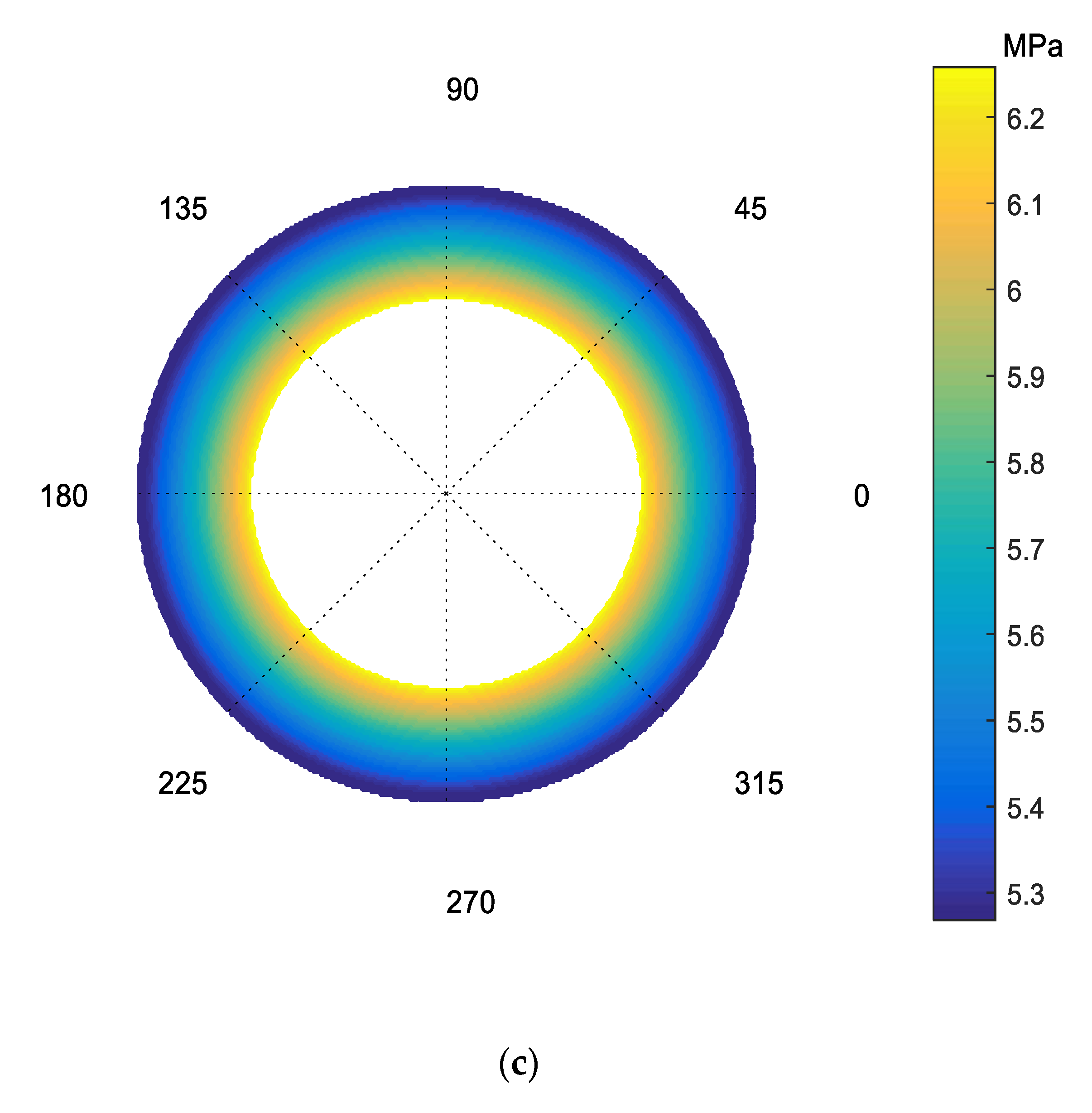
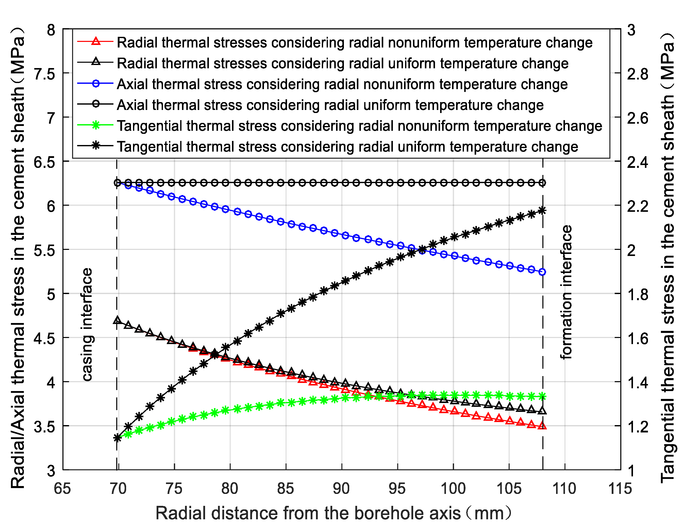
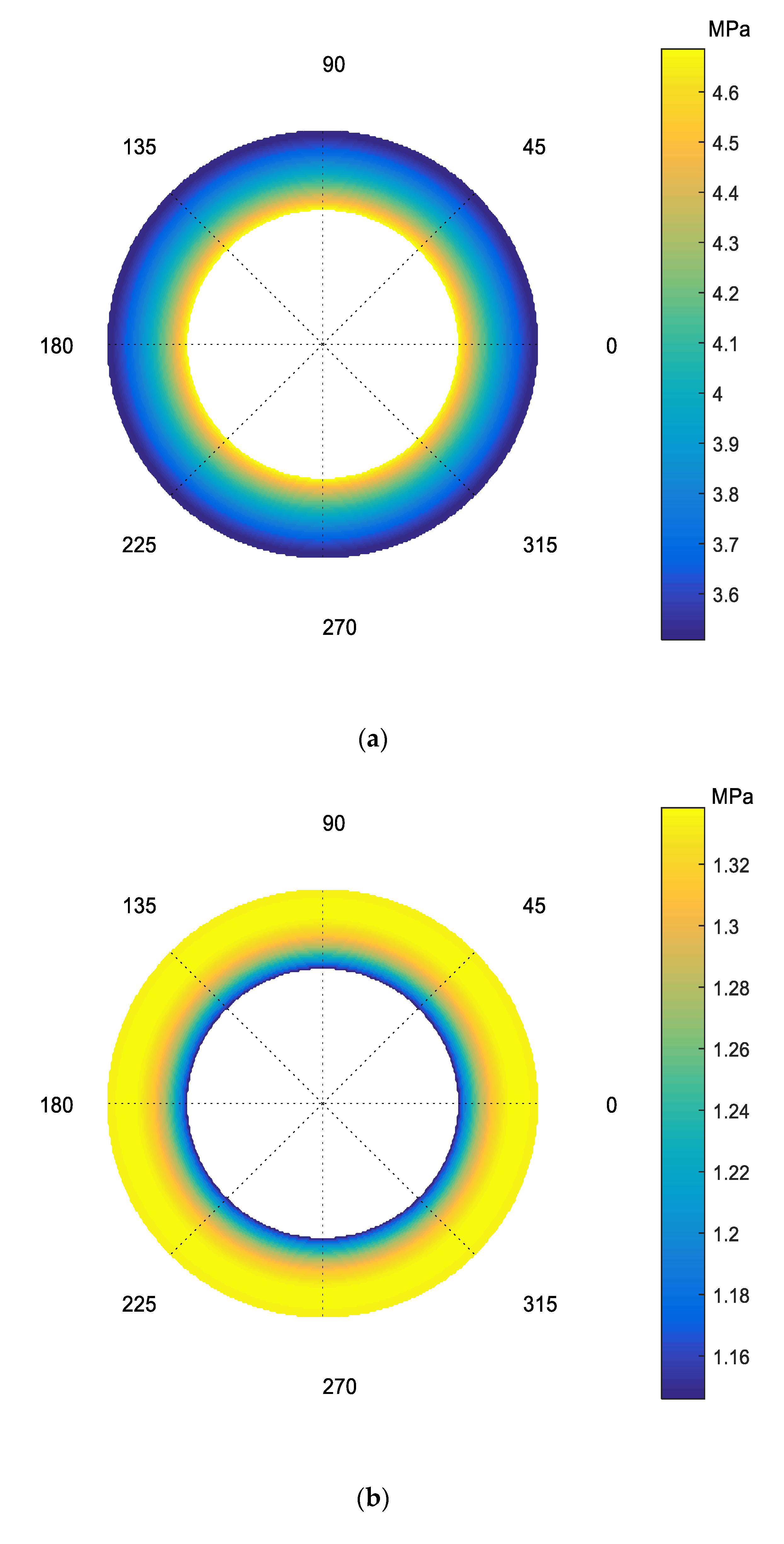
3.2.1. Thermal Stress under Basic Calculation Parameters

Figure 2 shows the compared radial distribution of the radial, tangential, and axial thermal stresses in the cement sheath under radial uniform and nonuniform temperature change. It can be seen from Figure 2 that except for radial thermal stress, both tangential and axial thermal stresses are obviously different under two situations, and the difference increases significantly as it moves towards the formation interface. Consequently, the present model is more in line with reality compared with previous models which consideration radial uniform temperature change.
Figure 3 shows the corresponding radial, tangential, and axial thermal stresses counter, respectively, under radial nonuniform temperature change. As shown in Figure 2 and Figure 3, the cement sheath is subjected to three-dimensional tensile thermal stress during fracturing fluid injection. The radial and axial thermal stresses are both obviously larger than tangential thermal stress, which indicates that wellbore temperature decrease is more likely to induce radial and axial micro crack in the cement sheath. Meanwhile, both the maximum radial thermal stress (4.69 MPa) and the maximum axial thermal stress (6.26 MPa) occur at the casing interface while the maximum tangential thermal stress (1.34 MPa) is near the formation interface, indicating that cement sheath will start to fail from casing interface.

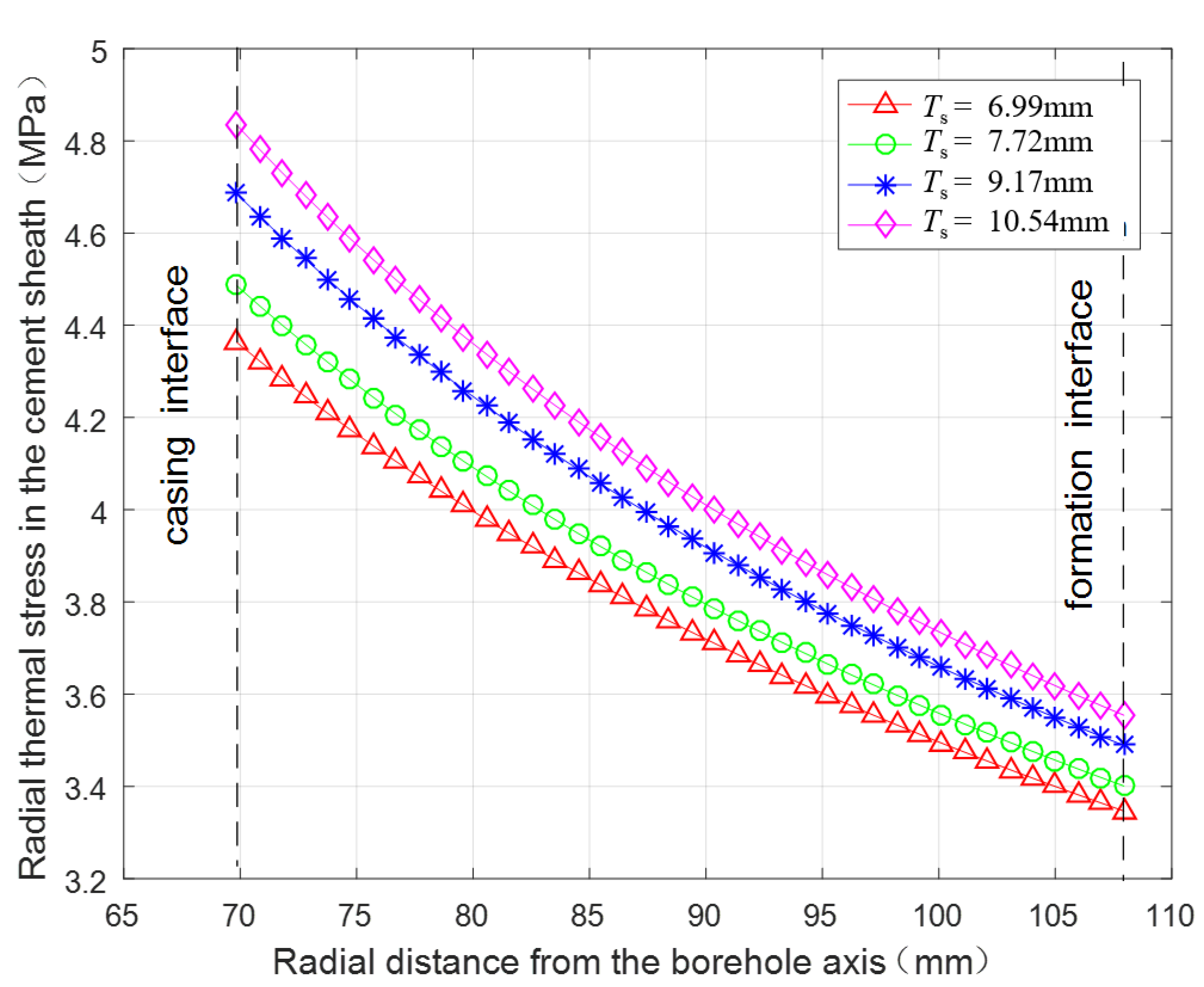
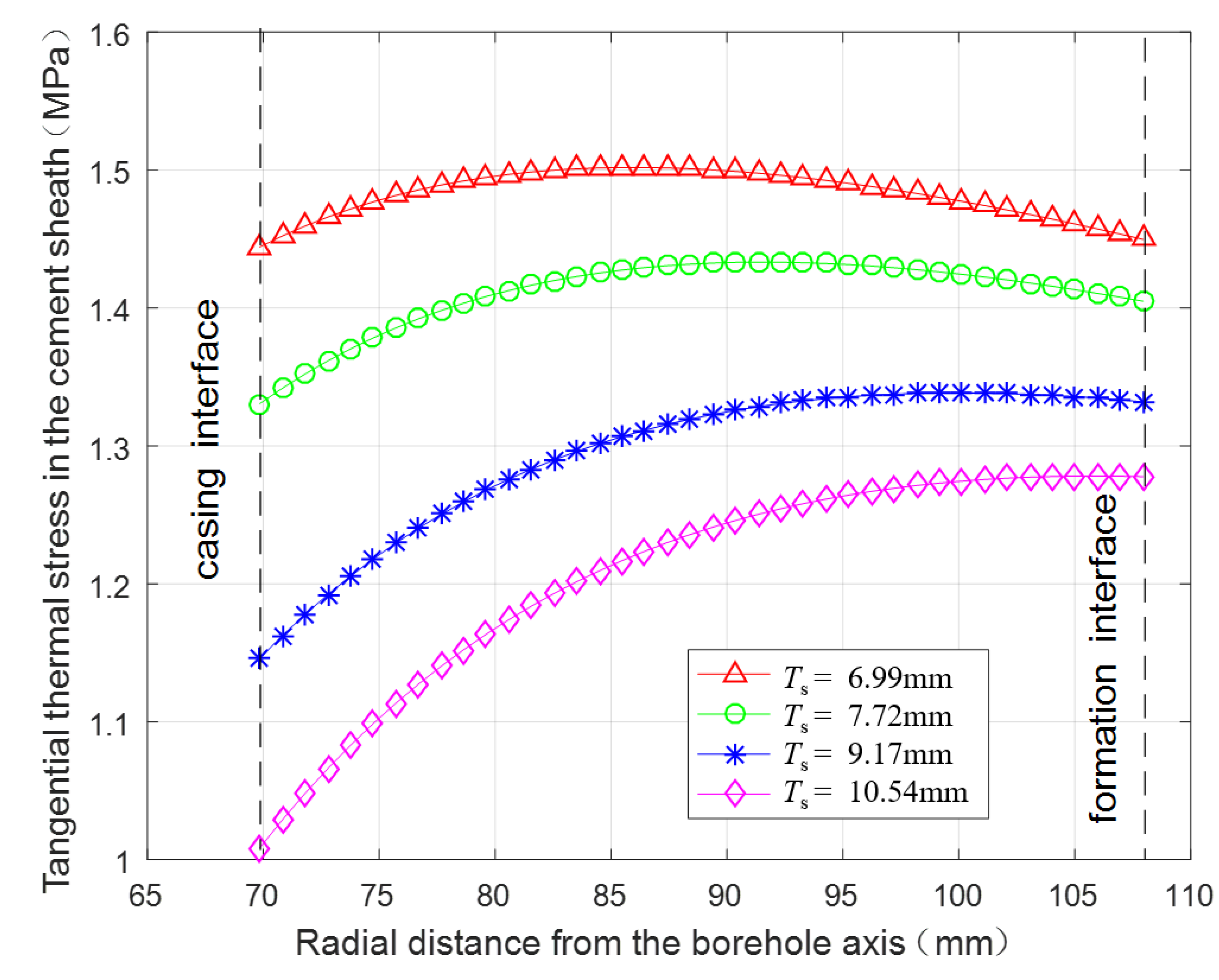
3.2.2. Thermal Stress under Different Wall Thicknesses of the Casing

Figure 4, Figure 5 and Figure 6 presented the radial distribution of the radial, tangential, and axial thermal stresses, respectively, in the cement sheath with the wall thickness (Ts) of 6.99 mm, 7.72 mm, 9.17 mm, and 10.54 mm. It can be seen from Figure 4, Figure 5 and Figure 6 that as the casing wall thickness increases, the radial tensile thermal stress gradually increases, the tangential tensile thermal stress gradually decreases, but the axial tensile thermal stress is nearly constant. When casing wall thickness increases from 6.99 mm to 10.54 mm, the maximal radial thermal stress increases from 4.36 MPa to 4.83 MPa (10.8%), the maximal tangential thermal stress decreases from 1.50 MPa to 1.28 MPa (−14.6%). Meanwhile, the location of the maximal tangential thermal stress occurs gradually towards formation interface. In general, proper reduction of casing wall thickness in fracturing well can protect the cement sheath to some extent.

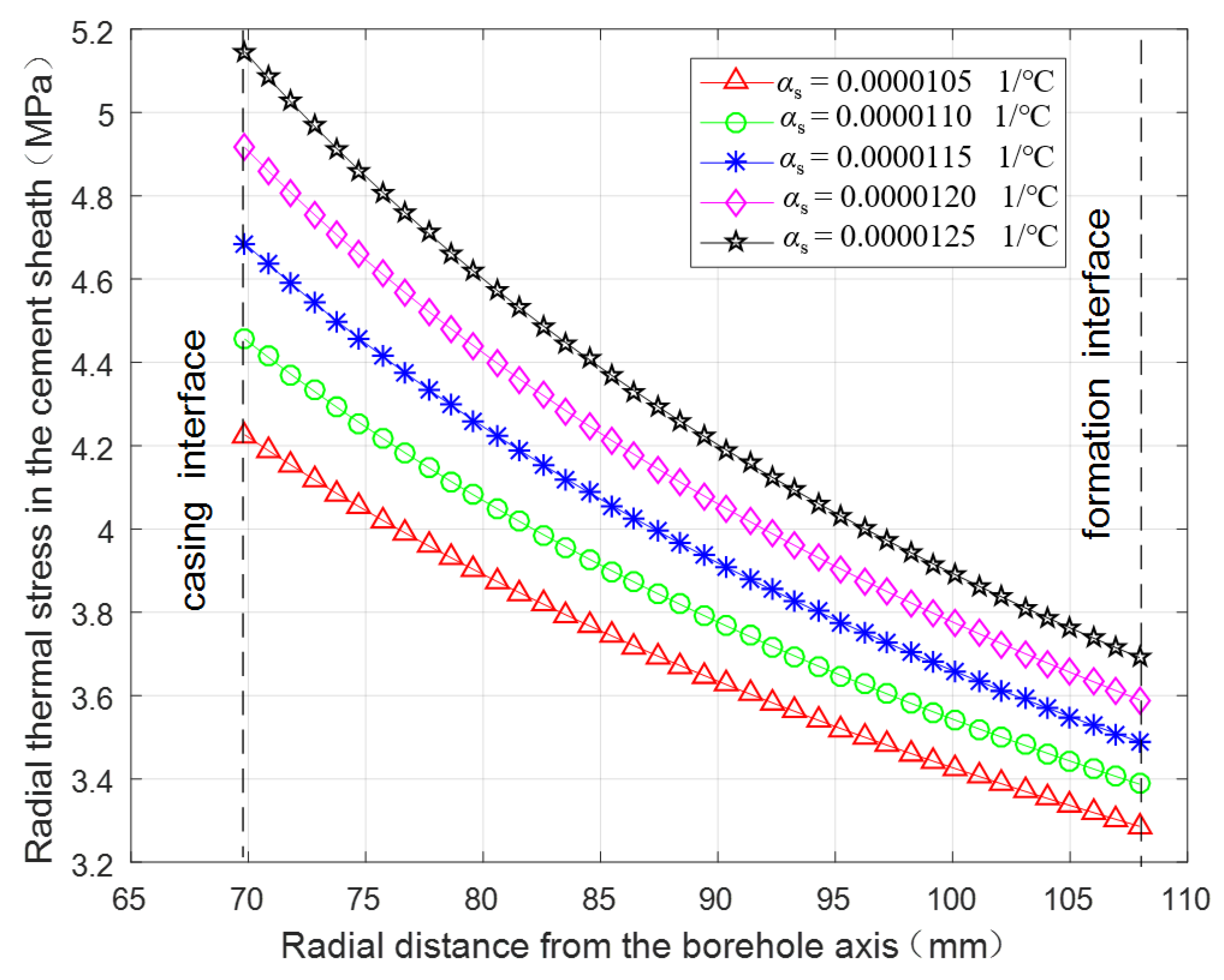
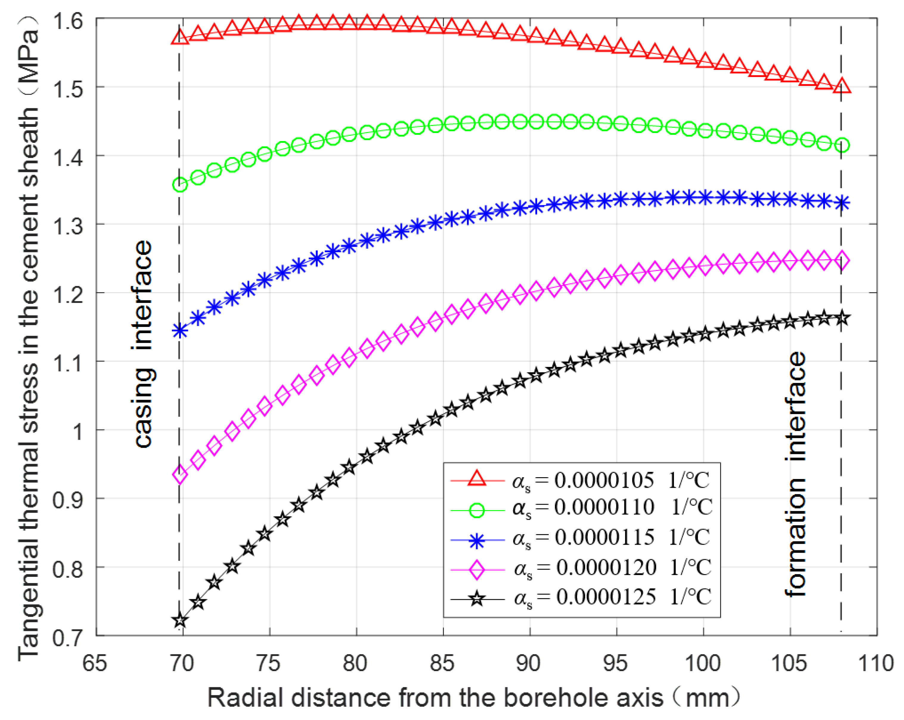
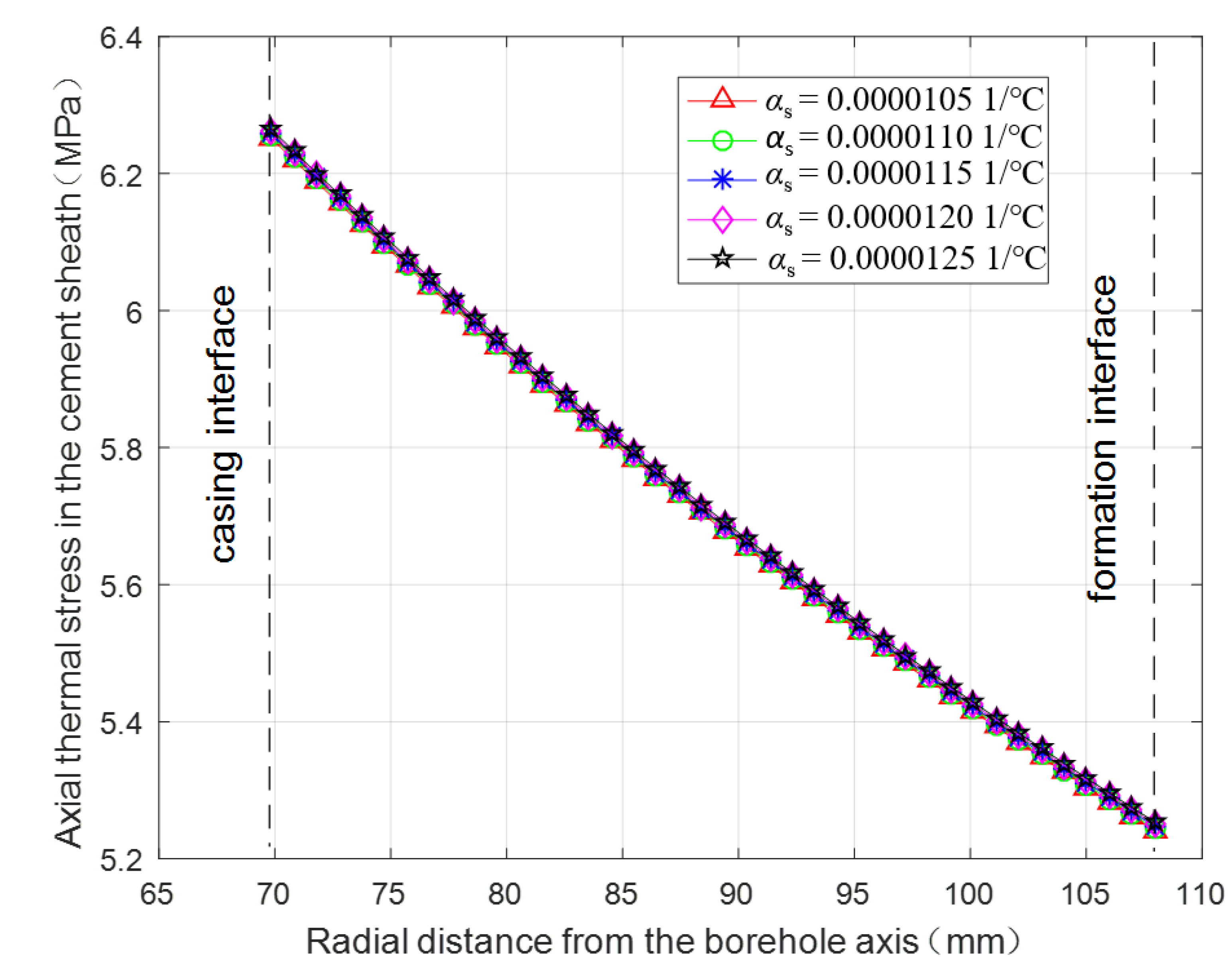
3.2.3. Thermal Stress under Different Linear Thermal Expansion Coefficients of the Casing

Figure 7, Figure 8 and Figure 9 present the radial distribution of the radial, tangential, and axial thermal stresses, respectively, in the cement sheath with the linear thermal expansion coefficient (αs) of 1.05 × 10⁻⁵ 1/°C to 1.25 × 10⁻⁵ 1/°C. It can be seen from Figure 7, Figure 8 and Figure 9 that as linear thermal expansion coefficient of the casing increases, the radial tensile thermal stress gradually increases, the tangential tensile thermal stress gradually decreases while the axial tensile thermal stress is nearly constant. When linear thermal expansion coefficient of the casing increases from 1.05 × 10⁻⁵ 1/°C to 1.25 × 10⁻⁵ 1/°C, the maximal radial thermal stress increases from 4.23 MPa to 5.15 MPa (21.7%), the maximal tangential thermal stress decreases from 1.59 MPa to 1.16 MPa (−27.0%). Meanwhile, the location of the maximal tangential thermal stress occurs also gradually towards formation interface. In general, proper reduction of casing linear thermal expansion coefficient in fracturing well can protect cement sheath to some extent.

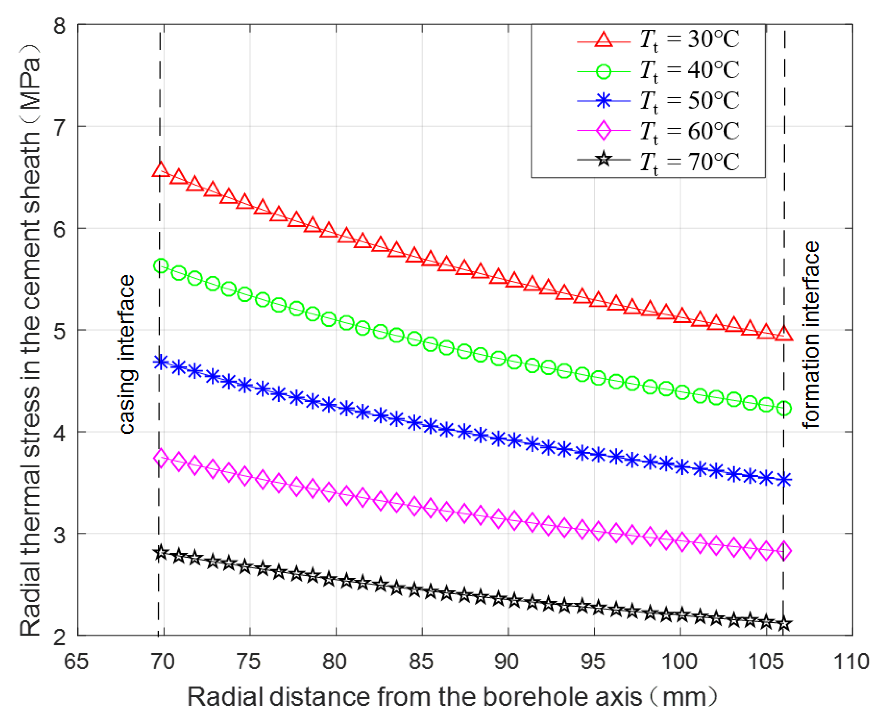
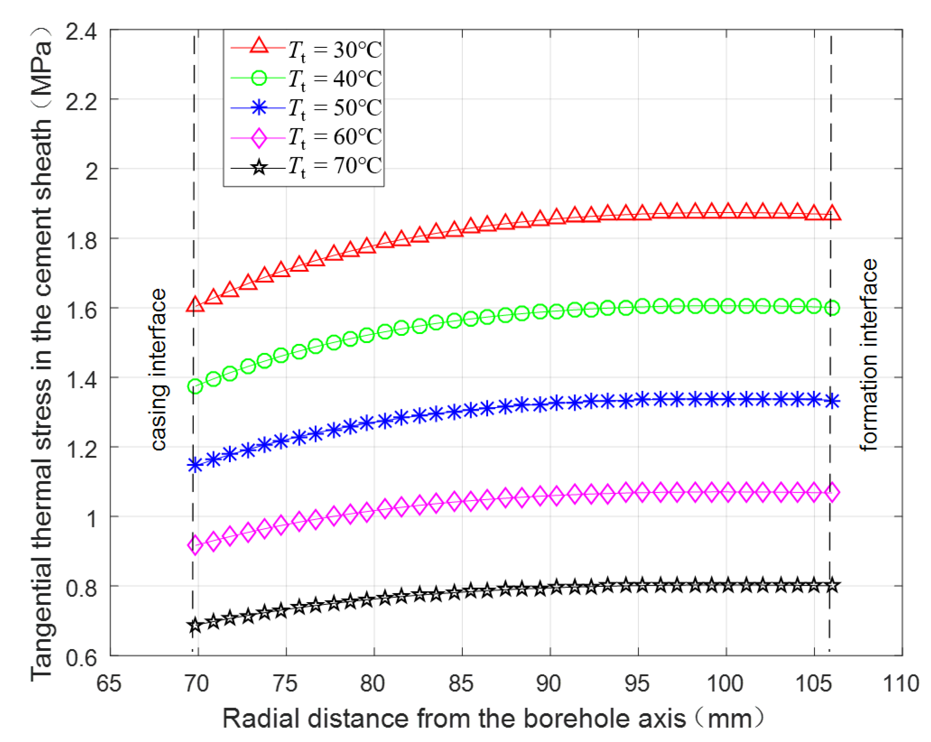
3.2.4. Thermal Stress under Different Wellbore Temperatures after Fracturing Fluid Injection

Figure 10, Figure 11 and Figure 12 present the radial distribution of the radial, tangential, and axial thermal stresses, respectively, in the cement sheath with the wellbore temperature (Tt) of 30 °C, 40 °C, 50 °C, 60 °C, and 70 °C. It can be seen from Figure 10, Figure 11 and Figure 12 that as wellbore temperature increases after fracturing fluid injection, all three-dimensional tensile thermal stresses gradually decrease. When wellbore temperature after fracturing fluid injection increases from 30 °C to 70 °C, the maximal radial thermal stress decreases from 6.56 MPa to 2.81 MPa (−57.1%), the maximal tangential thermal stress decreases from 1.87 MPa to 0.80 MPa (−57.1%), and the maximal axial thermal stress decreases from 8.76 MPa to 3.76 MPa (−57.1%). Consequently, improving the temperature of the fracturing fluid properly can be effective for cement sheath protection.

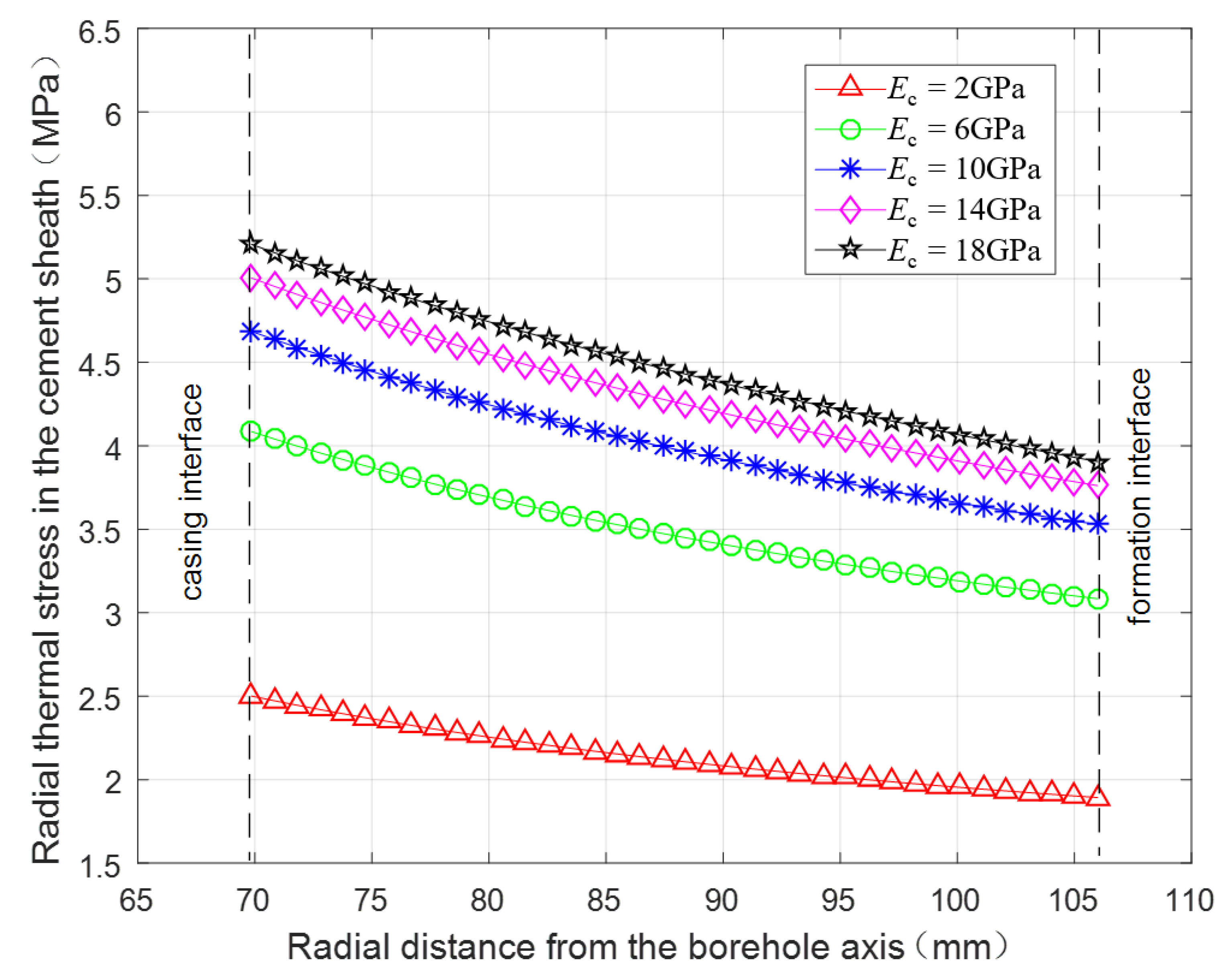
3.2.5. Thermal Stress under Different Elasticity Moduli of the Cement Sheath

Figure 13, Figure 14 and Figure 15 present the radial distribution of the radial, tangential and axial thermal stresses, respectively, in the cement sheath with the elasticity moduli (Ec) of 2 GPa, 6 GPa, 10 GPa, 14 GPa, and 18 GPa. It can be seen from Figure 13, Figure 14 and Figure 15 that as the elasticity modulus of the cement sheath increases, the radial tensile thermal stress gradually increases but with a decreasing amplitude, the tangential tensile thermal stress generally increases but its maximum gradually occurs from formation interface to casing interface, and the axial tensile thermal stress also gradually increases. When elasticity modulus of the cement sheath increases from 2 GPa to 18 GPa, the maximal radial thermal stress increases from 2.50 MPa to 5.21 MPa (108%), the maximal tangential thermal stress increases from 0.89 MPa to 1.60 MPa (79.8%), and the maximal axial thermal stress increases from 1.59 MPa to 10.56 MPa (564%). Consequently, adoption of a cement sheath with a low elasticity modulus can decrease the thermal stresses for geothermal wells during fracturing.

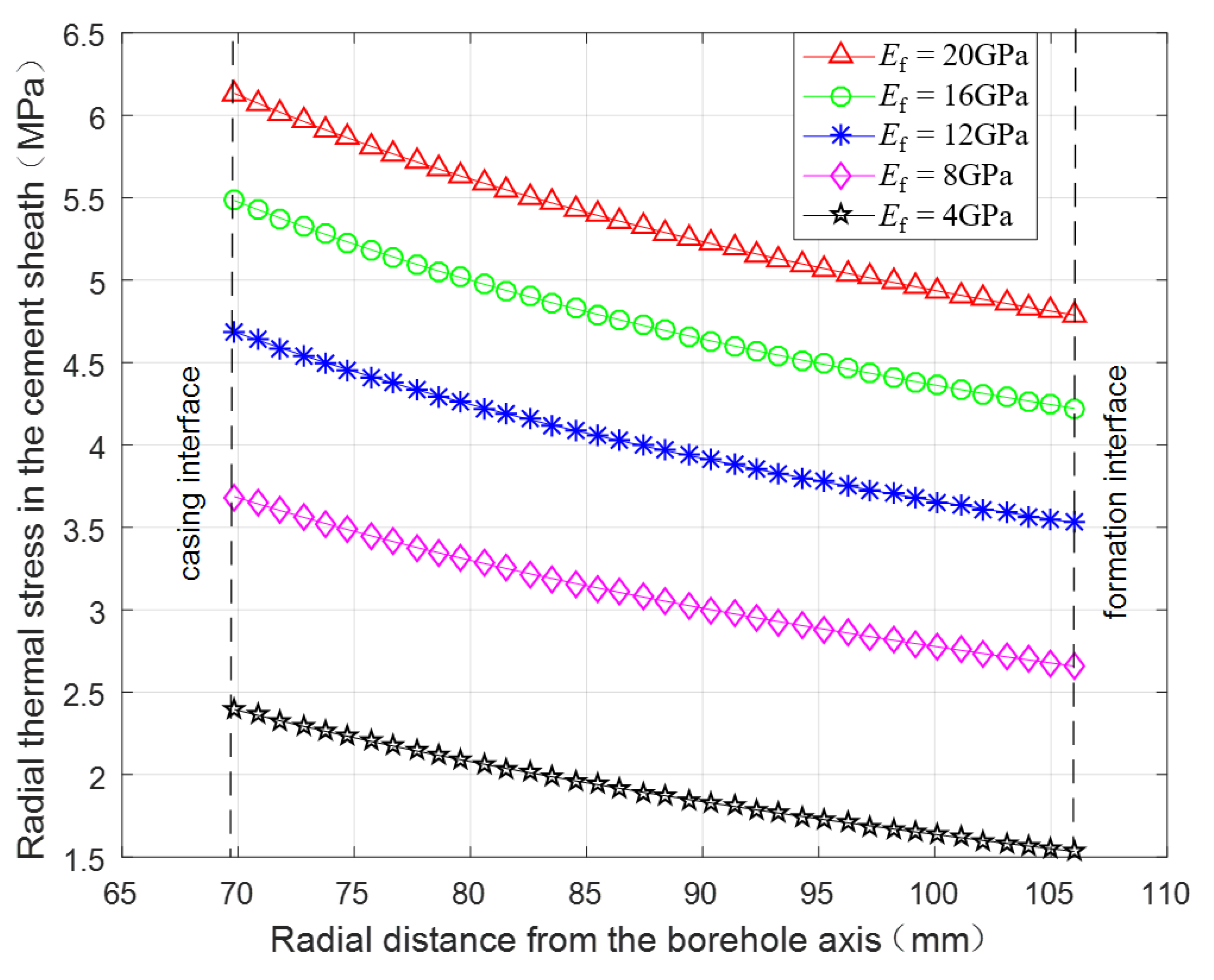
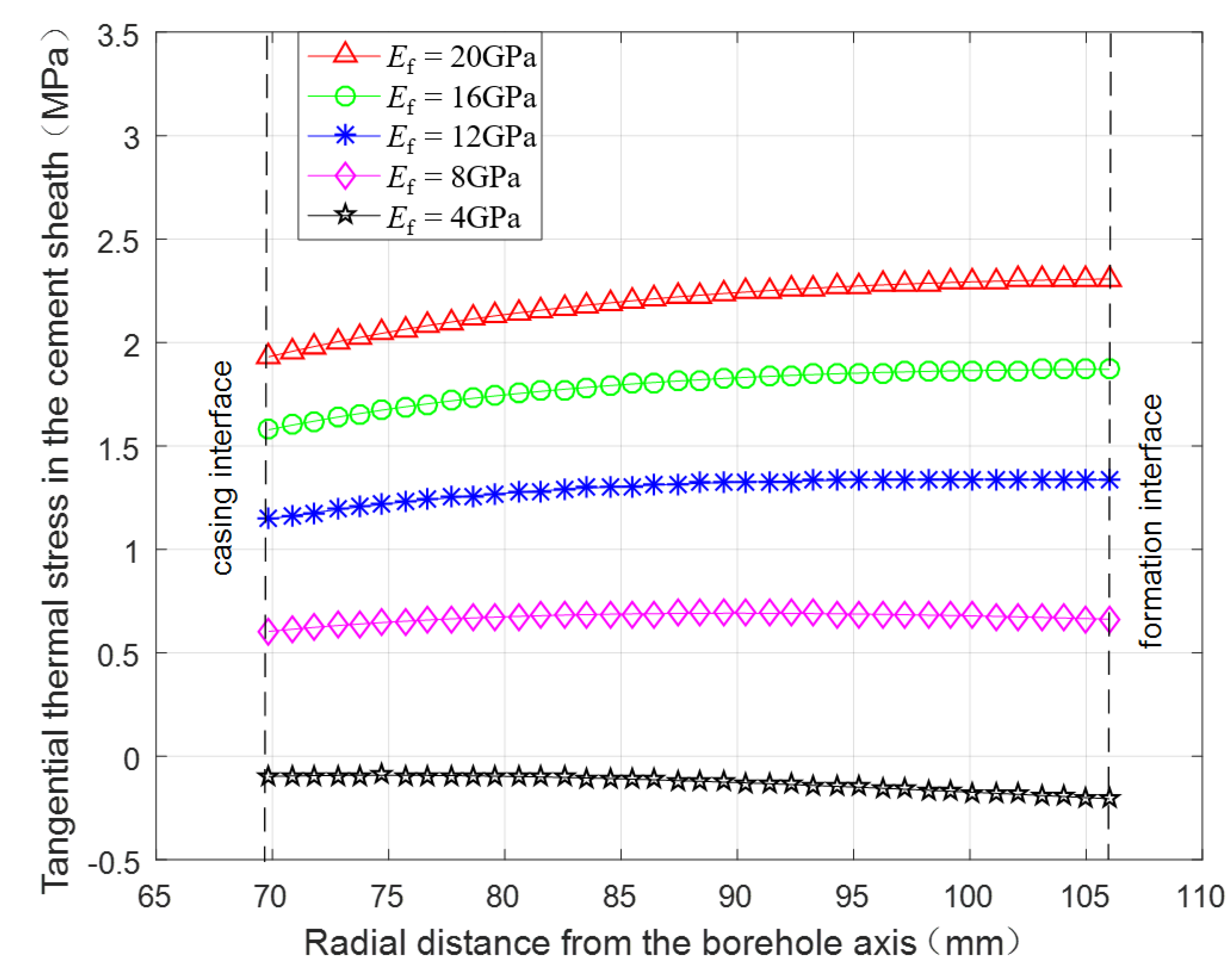
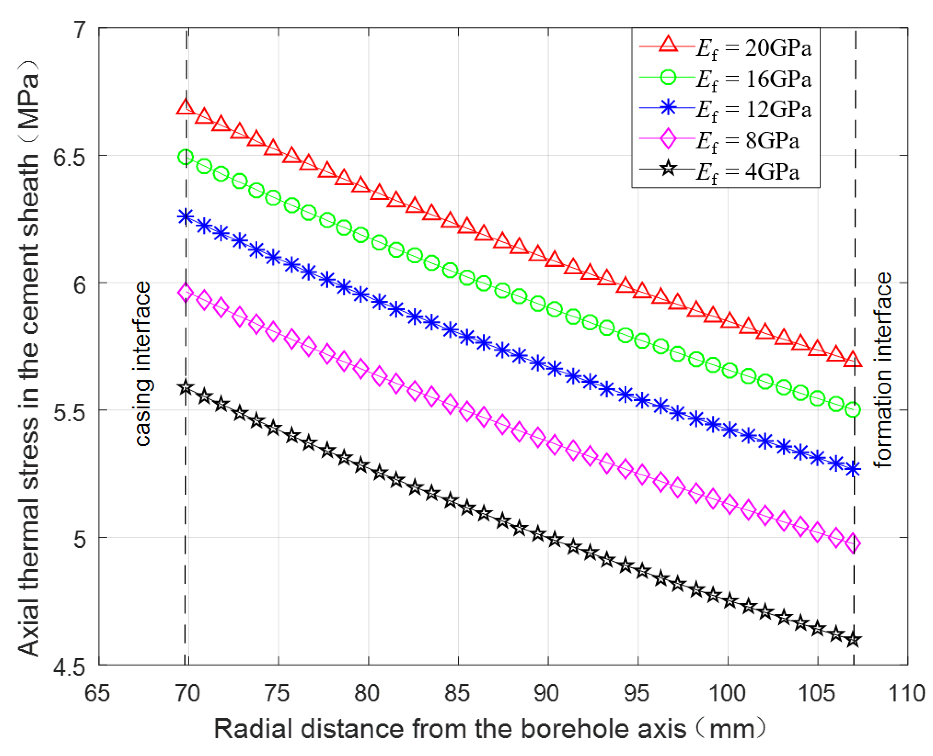
3.2.6. Thermal Stress under Different Elasticity Moduli of the Formation

Figure 16, Figure 17 and Figure 18 present the radial distribution of the radial, tangential, and axial thermal stresses, respectively, in the cement sheath with the elasticity moduli of the formation Ef is 4 GPa, 8 GPa, 12 GPa, 16 GPa, and 20 GPa. It can be seen from Figure 16, Figure 17 and Figure 18 that as the elasticity modulus of the formation increases, all three-dimensional thermal stresses gradually increase but with decreasing amplitude. When the elasticity modulus of the formation increases from 4 GPa to 20 GPa, the maximal radial thermal stress increases from 2.39 MPa to 6.13 MPa (156%), the maximal tangential thermal stress increases from −0.09 MPa to 2.31 MPa (261.3%), and the maximal axial thermal stress increases from 5.59 MPa to 6.68 MPa (19.5%). Meanwhile, the maximum tangential thermal stress gradually occurs from the casing interface to the formation interface. Consequently, cement sheath will fail more easily in a formation with a higher elasticity modulus.

4. Conclusions

In the present paper, a thermal stress model of a casing-cement sheath-formation combined system for geothermal wells during fracturing has been proposed with consideration to radial nonuniform temperature change. The influence of the main parameters on the radial distribution of the radial, tangential, and axial thermal stresses in the cement sheath were analyzed. And the following main conclusions can be drawn:
  • The radial and axial tensile thermal stresses are both obviously larger than tangential tensile thermal stress. The maximum radial and axial thermal stresses always occur at the casing interface while the location of the maximum tangential thermal stress is varying.
  • The thermal stresses are more likely to induce radial and axial micro cracks in the cement sheath and cement sheath will fail more easily from the casing interface.
  • Decreasing the casing wall thickness, casing linear thermal expansion coefficient, and cement sheath elasticity modulus, and increasing the fracturing fluid temperature can be effective for protecting cement sheath. The cement sheath will fail more easily in a formation with a higher elasticity modulus.

Author Contributions

Conceptualization, H.X., B.Y., and T.M.; Investigation, H.X. and N.P.; Methodology, H.X. and N.P.; Writing—original draft, H.X. and N.P.; Writing—review and editing, B.Y. and T.M.

Funding

This research was funded by the National Natural Science Foundation of China (Grant No. 51804060), the Basic and Frontier Research Programs of Chongqing Science & Technology Commission of China (Grant No. cstc2018jcyjAX0614), the Science and Technology Research Program of Chongqing Municipal Education Commission (Grant No. KJ1713321), the Research Foundation of Chongqing University of Science & Technology (Grant No. CK2016B13), and the Program of Introducing Talents of Discipline to Chinese Universities (111 Plan) (Grant No. D18016).

Conflicts of Interest

The authors declare no conflict of interest.

List of Symbols

εr, εθ, εzRadial, tangential, and axial strain of cylinder, respectively, dimensionless
σr, σθ, σzRadial, tangential, and axial thermal stress of cylinder, respectively, MPa
σrs, σθs, σzsRadial, tangential, and axial thermal stress of casing, respectively, MPa
σrc, σθc, σzcRadial, tangential, and axial thermal stress of cement sheath, respectively, MPa
σrf, σθf, σzfRadial, tangential, and axial thermal stress of formation, respectively, MPa
uRadial thermal displacement, mm
us, uc, ufRadial thermal displacement for casing, cement sheath, and formation, respectively, mm
E, Es, Ec, EfElasticity modulus of ordinary cylinder, casing, cement sheath, and formation respectively, MPa
μ, μs, μc, μfPoisson’s ratio of ordinary cylinder, casing, cement sheath, and formation, respectively, dimensionless
α, αs, αc, αfLinear thermal expansion coefficient of ordinary cylinder, casing, cement sheath, and formation, respectively, 1/°C
aInternal radius of thick wall cylinder, mm
rRadial distance from the axis of wellbore, mm
riInside radius of casing, mm
r1Outside radius of casing or inside radius of cement sheath, mm
r2Outside radius of cement sheath or inside radius of formation, mm
roOutside radius of formation, mm
TsWall thickness of the casing, mm
Tb(r)Temperature value at the radius of r before fracturing fluid injection, °C
Ta(r)Temperature value at the radius of r after fracturing fluid injection, °C
T(r)Temperature change value at the radius of r after fracturing fluid injection, °C
TiWellbore temperature before fracturing fluid injection, °C
TtWellbore temperature after fracturing fluid injection, °C
TeFormation temperature, °C
C1, C1s, C1c, C1fUndetermined coefficients, dimensionless
C2, C2s, C2c, C2fUndetermined coefficients, m2
[A], {B}Coefficient matrix and constant vector for Equation (15), respectively

References

  1. Wang, K.; Yuan, B.; Ji, G.; Wu, X. A comprehensive review of geothermal energy extraction and utilization in oilfields. J. Pet. Sci. Eng. 2018, 168, 465–477. [Google Scholar] [CrossRef]
  2. Hou, J.; Cao, M.; Liu, P. Development and utilization of geothermal energy in China: Current practices and future strategies. Renew. Energy 2018, 125, 401–412. [Google Scholar] [CrossRef]
  3. Zhang, X.; Hu, Q. Development of Geothermal Resources in China: A Review. J. Earth Sci. 2018, 29, 452–467. [Google Scholar] [CrossRef]
  4. Shao, S.; Ranjith, P.G.; Wasantha, P.L.P.; Chen, B.K. Experimental and numerical studies on the mechanical behaviour of Australian Strathbogie granite at high temperatures: An application to geothermal energy. Geothermics 2015, 54, 96–108. [Google Scholar] [CrossRef]
  5. Kumari, W.G.P.; Ranjith, P.G.; Perera, M.S.A.; Shao, S.; Chen, B.K.; Lashin, A.; AlArifi, N.; Rathnaweera, T.D. Mechanical behaviour of Australian Strathbogie granite under in-situ stress and temperature conditions: An application to geothermal energy extraction. Geothermics 2017, 65, 44–59. [Google Scholar] [CrossRef]
  6. Kumari, W.G.P.; Ranjith, P.G.; Perera, M.S.A.; Chen, B.K. Experimental investigation of quenching effect on mechanical, microstructural and flow characteristics of reservoir rocks: Thermal stimulation method for geothermal energy extraction. J. Pet. Sci. Eng. 2018, 162, 419–433. [Google Scholar] [CrossRef]
  7. Kumari, W.G.P.; Ranjith, P.G.; Perera, M.S.A.; Li, X.; Li, L.H.; Chen, B.K.; AvanthiIsaka, B.L.; De Silva, V.R.S. Hydraulic fracturing under high temperature and pressure conditions with micro CT applications: Geothermal energy from hot dry rocks. Fuel 2018, 230, 138–154. [Google Scholar] [CrossRef]
  8. Wu, B.; Ma, T.; Feng, G.; Chen, Z.; Zhang, X. An approximate solution for predicting the heat extraction and preventing heat loss from a closed-loop geothermal reservoir. Geofluids 2017, 2017, 2041072. [Google Scholar] [CrossRef]
  9. Yang, S.Q.; Ranjith, P.G.; Jing, H.W.; Tian, W.L.; Ju, Y. An experimental investigation on thermal damage and failure mechanical behavior of granite after exposure to different high temperature treatments. Geothermics 2017, 65, 180–197. [Google Scholar] [CrossRef]
  10. Bina, S.M.; Jalilinasrabady, S.; Fujii, H.; Pambudi, N.A. Classification of geothermal resources in Indonesia by applying exergy concept. Renew. Sustain. Energy Rev. 2018, 93, 499–506. [Google Scholar] [CrossRef]
  11. Moeck, I.S. Catalog of geothermal play types based on geologic controls. Renew. Sustain. Energy Rev. 2014, 37, 867–882. [Google Scholar] [CrossRef]
  12. Lu, S.M. A global review of enhanced geothermal system (EGS). Renew. Sustain. Energy Rev. 2018, 81, 2902–2921. [Google Scholar] [CrossRef]
  13. Wan, Z.; Zhao, Y.; Kang, J. Forecast and evaluation of hot dry rock geothermal resource in China. Renew. Energy 2005, 30, 1831–1846. [Google Scholar] [CrossRef]
  14. Hofmann, H.; Babadagli, T.; Yoon, J.S.; Blöcher, G.; Zimmermann, G. A hybrid discrete/finite element modeling study of complex hydraulic fracture developments for enhanced geothermal systems (EGS) in granitic basements. Geothermics 2016, 64, 362–381. [Google Scholar] [CrossRef]
  15. Hou, B.; Chen, M.; Zhimeng, L.I.; Wang, Y.; Diao, C. Propagation area evaluation of hydraulic fracture networks in shale gas reservoirs. Pet. Explor. Dev. 2014, 41, 833–838. [Google Scholar] [CrossRef]
  16. Shadravan, A.; Schubert, J.; Amani, M.; Teodoriu, C. HPHT cement sheath integrity evaluation method for unconventional wells. In Proceedings of the SPE International Conference on Health, Safety, and Environment, Long Beach, CA, USA, 17–19 March 2014; SPE 168321. Society of Petroleum Engineers: Richardson, TX, USA, 2014. [Google Scholar]
  17. Wang, W.; Taleghani, A.D. Cement sheath integrity during hydraulic fracturing: An integrated modeling approach. In Proceedings of the SPE Hydraulic Fracturing Technology Conference, The Woodlands, TX, USA, 4–6 February 2014; SPE 168642. Society of Petroleum Engineers: Richardson, TX, USA, 2014. [Google Scholar]
  18. Vrålstad, T.; Skorpa, R.; Opedal, N.; Andrade, J.D. Effect of thermal cycling on cement sheath integrity: Realistic experimental tests and simulation of resulting leakages. In Proceedings of the SPE Thermal Well Integrity and Design Symposium, Banff, AB, Canada, 23–25 November 2015; SPE 178467. Society of Petroleum Engineers: Richardson, TX, USA, 2015. [Google Scholar]
  19. Tian, Z.; Shi, L.; Qiao, L. Research of and countermeasure for wellbore integrity of shale gas horizontal well. Nat. Gas Ind. 2015, 35, 70–76. [Google Scholar]
  20. Teodoriu, C.; Falcone, G. Comparing completion design in hydrocarbon and geothermal wells: The need to evaluate the integrity of casing connections subject to thermal stresses. Geothermics 2009, 38, 238–246. [Google Scholar] [CrossRef]
  21. Zhou, C.; Wan, Z.; Zhang, Y.; Gui, B. Experimental study on hydraulic fracturing of granite under thermal shock. Geothermics 2018, 71, 146–155. [Google Scholar] [CrossRef]
  22. Thiercelin, M.J.; Dargaud, B.; Baret, J.F.; Rodriquez, W.J. Cement design based on cement mechanical response. SPE Drill. Complet. 1998, 13, 266–273. [Google Scholar] [CrossRef]
  23. Jing, L.I.; Lin, C.Y.; Yang, S.C.; Zhi, Y.; Chen, S. Theoretical solution of thermal stress for casing-cement-formation coupling system. J. China Univ. Pet. 2009, 33, 63–69. [Google Scholar]
  24. Li, Y.; Liu, S.; Wang, Z.; Yuan, J.; Qi, F. Analysis of cement sheath coupling effects of temperature and pressure in non-uniform in-situ stress field. In Proceedings of the International Oil and Gas Conference and Exhibition in China, Beijing, China, 8–10 June 2010; SPE 131878. Society of Petroleum Engineers: Richardson, TX, USA, 2010. [Google Scholar]
  25. Teodoriu, C.; Ugwu, I.O.; Schubert, J.J. Estimation of casing-cement-formation interaction using a new analythical model. In Proceedings of the SPE EUROPEC/EAGE Annual Conference and Exhibition, Barcelona, Spain, 14–17 June 2010; SPE 131335. Society of Petroleum Engineers: Richardson, TX, USA, 2010. [Google Scholar]
  26. Bois, A.P.; Garnier, A.; Galdiolo, G.; Laudet, J.B. Use of a mechanistic model to forecast cement-sheath integrity. SPE Drill. Complet. 2012, 27, 303–314. [Google Scholar] [CrossRef]
  27. Haider, M.G.; Sanjayan, J.; Ranjith, P.G. Modeling of a wellbore composite cylinder system for cement sheath stress analysis in geological sequestration of CO2. In Proceedings of the 46th U.S. Rock Mechanics/Geomechanics Symposium, Chicago, IL, USA, 24–27 June 2012; ARMA 12-369. American Rock Mechanics Association: Alexandria, VA, USA, 2012. [Google Scholar]
  28. Bui, B.T.; Tutuncu, A.N. Modeling the failure of cement sheath in anisotropic stress field. In Proceedings of the SPE Unconventional Resources Conference Canada, Calgary, AB, Canada, 5–7 November 2013; SPE 167178. Society of Petroleum Engineers: Richardson, TX, USA, 2013. [Google Scholar]
  29. Xu, H.; Zhang, Z.; Shi, T.; Xiong, J.Y. Influence of the WHCP on cement sheath stress and integrity in HTHP gas well. J. Pet. Sci. Eng. 2015, 126, 174–180. [Google Scholar]
  30. Xu, B.; Wang, J. Theory of Elastic Mechanics; Tsinghua University Press: Beijing, China, 2007. [Google Scholar]
  31. Li, Q.; Wang, N. Numerical Analysis; Tsinghua University Press: Beijing, China, 2008. [Google Scholar]
Figure 1. Thermal stress calculation model of casing-cement sheath-formation combined system.
Energies 11 02581 g001
Figure 2. Radial distribution of radial, tangential, and axial thermal stresses in the cement sheath.
Energies 11 02581 g002
Figure 3. Thermal stresses counter in the cement sheath. (a) Radial thermal stress; (b) Tangential thermal stress; (c) Axial thermal stress.
Energies 11 02581 g003aEnergies 11 02581 g003b
Figure 4. Radial distribution of the radial thermal stress in the cement sheath under different wall thicknesses of the casing.
Energies 11 02581 g004
Figure 5. Radial distribution of the tangential thermal stress in the cement sheath under different wall thicknesses of the casing.
Energies 11 02581 g005
Figure 6. Radial distribution of the axial thermal stress in the cement sheath under different wall thicknesses of the casing.
Energies 11 02581 g006
Figure 7. Radial distribution of the radial thermal stress in the cement sheath under different linear thermal expansion coefficients of the casing.
Energies 11 02581 g007
Figure 8. Radial distribution of the tangential thermal stress in the cement sheath under different linear thermal expansion coefficients of the casing.
Energies 11 02581 g008
Figure 9. Radial distribution of the axial thermal stress in the cement sheath under different linear thermal expansion coefficients of the casing.
Energies 11 02581 g009
Figure 10. Radial distribution of the radial thermal stress in the cement sheath under different wellbore temperatures after fracturing fluid injection.
Energies 11 02581 g010
Figure 11. Radial distribution of the tangential thermal stress in the cement sheath under different wellbore temperatures after fracturing fluid injection.
Energies 11 02581 g011
Figure 12. Radial distribution of the axial thermal stress in the cement sheath under different wellbore temperatures after fracturing fluid injection.
Energies 11 02581 g012
Figure 13. Radial distribution of the radial thermal stress in the cement sheath under different elasticity moduli of the cement sheath.
Energies 11 02581 g013
Figure 14. Radial distribution of the tangential thermal stress in the cement sheath under different elasticity moduli of the cement sheath.
Energies 11 02581 g014
Figure 15. Radial distribution of the axial thermal stress in the cement sheath under different elasticity moduli of the cement sheath.
Energies 11 02581 g015
Figure 16. Radial distribution of the radial thermal stress in the cement sheath under different elasticity moduli of the formation.
Energies 11 02581 g016
Figure 17. Radial distribution of the tangential thermal stress in the cement sheath under different elasticity moduli of the formation.
Energies 11 02581 g017
Figure 18. Radial distribution of the axial thermal stress in the cement sheath under different elasticity moduli of the formation.
Energies 11 02581 g018
Table 1. Basic input parameters.
NumberSymbolValueUnitNumberSymbolValueUnit
1ri60.68mm9Ec10GPa
2r169.85mm10Ef12GPa
3r2107.95mm11μs0.30dimensionless
4ro1079.5mm12μc0.19dimensionless
5αs1.15 × 10−51/°C13μf0.21dimensionless
6αc1.03 × 10−51/°C14Ti100°C
7αf1.03 × 10−51/°C15Tt50°C
8Es206GPa16Te100°C

