Abstract
Multi-physical field sensing and machine learning have drawn great attention in various fields such as sensor networks, robotics, energy devices, smart buildings, intelligent system and so on. In this paper, we present a novel efficient method for thermal and energy management based on bimodal airflow-temperature sensing and reinforcement learning, which expedites an exploration process by self-learning and adjusts action policy only through actuators interacting with the environment, being free of the controlled object model and priori experiences. In general, training of reinforcement learning requires a large amount of data iterations, which takes a long time and is not suitable for real-time control. Here, we propose an approach to speed up the learning process by indicating the action adjustment direction. We adopt tailor-designed bimodal sensors to simultaneously detect airflow and temperature field, which provides comprehensive information for reinforcement learning. The proposed thermal and energy management incorporates bimodal parametric sensing with an improved actor-critic algorithm to realize self-learning control. Experiments of thermal and energy management in a multi-module integrated system validate the effectiveness of the proposed methodology, which demonstrate high efficiency, fast response, and good robustness in various control scenarios. The proposed methodology can be widely applied to thermal and energy management of diverse integrated systems.
1. Introduction
Multi-physical field sensing and control is a technology now widely used in various areas such as sensor networks, robotics, smart buildings, and instrumentations, to name a few [1,2,3]. With the rapid development of artificial intelligence technology, machine learning has become a great potential strategy to execute measurement and control missions for versatile complex systems [1]. Thermal and energy management is a general issue that has been commonly observed in electromechanical equipment, energy devices, constructions and so forth [4,5,6]. Due to the easy operation and high efficiency, forced air cooling has been suggested as the most commonly used strategy for dealing with thermal control in areas such as plug-in hybrid electric vehicle [7], data center [8] and handheld polymerase chain reaction (PCR) device [9]. The fundamental principle of forced air cooling is adjusting the airflow to regulate heat dissipation and thermal distribution in a bounded space. In the industry, the proportional-integral-derivative (PID) algorithm is a popular feedback control method and has been widely used in various thermal management systems. However, at the same time, it is not suitable for multi-input multi-output (MIMO) control problems [10,11,12]. The MIMO temperature control problem is complex because of the strong coupling that exists in the controlled object. The modeling method is a common decoupling method. Li et al. [13] introduced a decoupling method in a double-level air flow dynamic vacuum system based on the neural networks and the prediction principle. Gil et al. [14] presented a constrained nonlinear adaptive model-based control framework applied to a distributed solar collector field. Shen et al. [15] presented the temperature uniformity control of large-scale vertical quench furnaces with a proportional–integral–derivative (PID) decoupling control system to eliminate the strong coupling effects of multi-heating zones. Although the modeling method is an effective approach to dealing with the coupling effects in some cases, it cannot meet all the demands in a practical application. Specifically, the control performances of this method usually depend on the accuracy of the developed model, which mainly relies on professional experience and highly restricts the robustness of the system.
Miniaturization, modularization, and multi-functionalization have become major development trends in instrumentation [16,17,18,19]. When the equipment gets miniaturized and integrated, it is an important issue that the thermal control in a narrow space and energy consumption need to be well managed, especially for the devices integrating multiple functional modules which have different thermal characteristics [4,5,19]. Generally, thermal control becomes arduous when working space turns smaller due to the strong thermal coupling [20]. It is essentially a multi-input multi-output system.
The airflow generated by the natural or forced convection is heat-transfer carrier that modulates thermal behavior [21]. As shown in Figure 1a, thermal energy from a heat source is taken away by the airflow. The airflow rate can speed up by adjusting the fan’s rotate speed, in which case, more thermal energy can be taken away and the temperature field lowers down. This suggests that airflow dominates the spatial thermal behavior. An effective thermal and energy management relies on the regulation of both temperature and airflow. In this paper, we adopt micro bimodal sensors that can simultaneously detect spatial airflow and temperature to support a fast, robust, self-adaptive thermal and energy management.
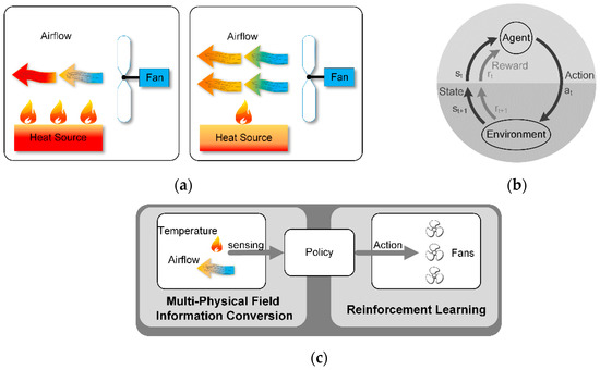
Figure 1.
(a) Schematic diagram of the relationship among fan, airflow and heat source. (b) Agent-environment interaction in reinforcement learning. (c) Representative structure of the temperature regulation method consisting of airflow and temperature sensing, control policy of fans. The policy is optimized by reinforcement learning with multi-physical field detection.
Machine learning based control has attracted great attention in the recent years. Reinforcement learning has been one of the most remarkable approaches, which has been successfully applied to deal with various problems [22,23,24,25], such as game, multi-agent systems, swarm intelligence, statistics, and genetic algorithms. The main process of reinforcement learning is shown in Figure 1b. First, the agent gets the state (s) and the reward (r) from the environment. The state represents the environment condition and the reward is a numerical signal. Second, the agent takes acts (a) onto the environment. The policy is learned by the agent itself. The environment changes its state with the effect of action and exports the reward that measures the action taken by the agent at the last state. Then, the agent adjusts its action policy for a better reward. Through constant exploration and trial and error, the agent figures out a policy to take action in different states [26]. Reinforcement learning is an effective way to realize automatic control without human experiences [27,28]. In fact, it is a self-learning method by interacting with the environment by trial and error, and then self-adjusting the strategy to the actuator.
In this paper, we propose a novel control method to deal with thermal and energy management based on multi-physical field sensing and reinforcement learning as shown in Figure 1c. The proposed methodology achieves a fast, robust, self-adaptive temperature control as well as energy management by using distributed bimodal airflow-temperature sensing and reinforcement learning. First, the distributed airflow-temperature sensors detect the airflow velocities and temperatures in the target space, which represent the environment states. Subsequently, reinforcement learning is introduced to evaluate the environment state and execute promptly control actions to cooling fans.
The remainder of this paper is organized as follows. Section 2 introduces the fundamental principle of reinforcement learning. In Section 3, the reinforcement learning control method based on airflow-temperature field sensing is presented. In Section 4, the proposed method is applied to thermal and energy management of a multi-module integrated system. The experiment results and discussions are presented in Section 5. The conclusion is drawn in Section 6.
2. Overview of Reinforcement Learning
As mentioned above, reinforcement learning is a methodology aimed for better reward via trial and error exploration. The behavior of the agent is defined by a policy π. It is a probability distribution which maps states to actions π: S → P(A), where S denotes state space and A denotes action space [24]. The transition dynamics and reward function can be written as p(st+1|st,at) and r(st,at), respectively. The expectation under policy π is denoted as Eπ. And the reward from a state is defined as the sum of discounted future rewards [22] by
where γ is the discounting factor varying from 0 to 1. Different policy gains different Rt and the goal of reinforcement learning is to learn a policy that maximizes the expectation Eπ[Rt].
The action-value function has been used in various reinforcement learning algorithms. It defines the expected reward after taking an action at in-state st under policy π:
where Qπ(st,at) denotes the value of state-action pair (st,at) following policy π [23]. The recursive Bellman equation can be used for calculating Qπ(st,at)
Assume adopting the deterministic policy, which can be described as a function μ: S ← A, the Bellman equation can be written as
Therefore, the expectation depends only on the interaction between the agent and the environment. Q(st,at) is approximated with parameter θQ, which can be optimized by minimizing the loss function [22,25,26]:
Employ actor-critic approach based on the deterministic policy gradient, it mainly contains a parameterized actor function μ(st|θμ), which maps states to actions, and a critic function Q(st,at|θQ), which describes the value of the state-action pair. The parameters in critic function are updated via the Bellman equation, while the actor’s parameters are updated by the chain rule [29]:
3. Reinforcement Learning Control Method Based on Airflow-Temperature Field Sensing
As mentioned above, reinforcement learning is an effective approach to realize automatically adjusting the control strategy only by interacting with the environment, which does not need human intervention. Multi-dimensional information of environment can enhance the state estimation accuracy. One of the characteristics of reinforcement learning is to accumulate a large amount of exploration experiences to predict future rewards and guide the current actions.
The difficulties in realizing the on-line reinforcement learning mainly lie in two aspects. First, it is difficult to accurately estimate the future rewards by a short exploration period. Second, in some cases, it is hard to receive the rewards at every moment, for example, a score can’t be obtained until the end of the game. In real control, more concerns are given to whether the change direction of the action is correct rather than the accuracy of the reward itself. Aiming at the characteristics of the control system, the theoretical methods of reinforcement learning can be appropriately simplified to realize practical applications.
As shown in Equation (1), the reward from a state can be defined as the sum of discounted future rewards obtained from the environment. Making the estimating depth as 1 for indicating the action adjustment direction gives
where r(st,at) denotes the received reward at time t + 1 after taking action at at state st. Then there is
A key point in reinforcement learning mission is the choice of the reward r(st,at). The reward function is related to the system performance. It is needed to convert the control object to the corresponding reward function. In real control systems, there is often more than one control objective to be achieved, such as minimizing energy consumption while meeting the thermal control accuracy. Without losing the generality, the above multi-objective control requirement can be expressed as
where fi(x) is an objective function with a threshold requirement, Di represents a constraint condition, and g(x) is an objective function pursuing an extreme value. Then r(st,at) can be expressed as
The control objective is converted to minimizing reward function r(st,at), where αi is the scale factor. fi(x) and g(x) are determined by the state of the environment and the definition of r(st,at) can be rewritten as
Based on the accurate prediction of the reward at time t + 1, the action strategy is adjusted automatically to make the reward function turn to the minimum.
Another two critical issues that need to be considered are the ways to get the state information and comprehending the mechanism of the reward affecting the action strategy. The state information includes various types of information related to the controlled object. The changes in controlled variables are related to multiple variables. The state information can be expressed as
where xi and yi denote different information types and x0 and y0 are their respective base values.
The mechanism of the reward affecting the action strategy determines the actor-critic approach based on the deterministic policy gradient and the selection of actor function μ(st|θμ) and critic function Q(st,at|θQ). Two neural networks are proposed. One is the policy network and the other is the value network. The schematic diagram is seen in Figure 2.
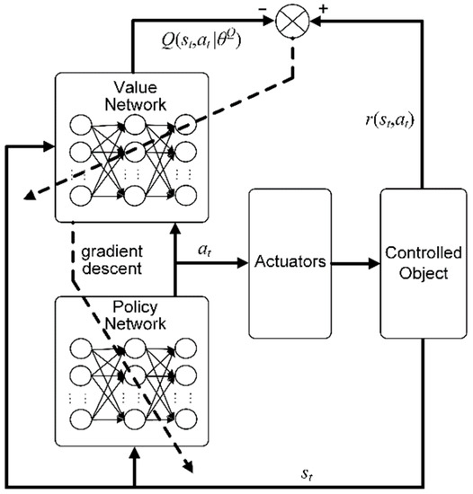
Figure 2.
Schematic diagram of on-line reinforcement learning control method.
Policy network is used to form a behavior strategy. It acquires the state information st of the controlled object and exports control signal at to the actuators. The value network is used to evaluate the behavior strategy. It inputs the state st, action at, and outputs critic function value Q(st,at|θQ). The value network updates its parameters by minimizing the deviations between the output and the received reward, while the policy network updates its parameters to reduce the value network’s output by gradient descent. Therefore, through the continuous interaction with the controlled object and the learnings of the value and policy networks, r(st,at) gradually decreases.
The above method can be written as the following flowchart shown in Figure 3. A random variable with a mean of 0 is added to the output of the policy network as the actual action, and its variance gradually reduces with time.
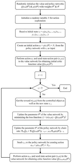
Figure 3.
Flowchart of on-line reinforcement learning method based on multi-physical field sensing.
4. Application of On-Line Reinforcement Learning Method
As mentioned above, effective thermal control and energy management rely on the regulation of both temperature and airflow. We developed micro bimodal sensors that can simultaneously detect airflow velocity and temperature. The bimodal sensor is comprised of micromachined hot-film anemometer and thermistor. The airflow sensing relies on the convective heat transfer from the electrically heated hot-film to the surrounding air. When a hot-film is heated to a higher temperature than the surrounding, the heat transfer related to the airflow velocity dominates its resistance by the thermoelectricity of the hot-film [30,31,32]. Therefore, the hot-film serves as an airflow detector. The temperature sensing is based on the thermoelectric conversion of the thermistor.
The circuit schematic diagram and the developed prototype of the bimodal sensor is shown in Figure 4a, where a hot-film resistor (hot-film), a temperature sensor, a compensating resistor and two balance resistors comprise a Wheatstone bridge. The hot-film resistor is used to detect airflow. The temperature resistor is used to detect the ambient temperature and also provides the temperature compensation for the anemometer. The hot-film resistor is fabricated by Pt. The bimodal sensor is operated in a constant temperature difference (CTD) feedback circuit shown in Figure 4a, which keeps the heating temperature of the hot-film resistor from the ambient temperature constant [30,31]. The compensating resistor Rc is used to adjust the heating temperature of the hot-film resistor Rh.
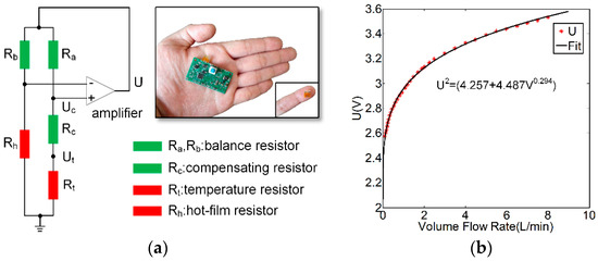
Figure 4.
(a) Schematic diagram and prototype of the airflow-temperature sensor. (b) Relationship between the output voltage U shown in (a) and airflow rate.
The characterization of the airflow sensor was conducted by using a wind tunnel experiment. The airflow rate was controlled by a mass flow controller (Fluke molbloc-L, Fluke Calibration, Everett, WA, USA). The relationship between the airflow velocity (denoted as V) and the output voltage U of the sensor was formulated as U2 = a + bVn [30,31], where a, b, and n are constants that were determined through the least squares estimation. Figure 4b shows the output voltage U against the airflow velocity.
The detected temperature can be deduced by the sensor outputs and calculated by
where R0 is resistance value of Rt at 0 °C, αt is temperature coefficient of Rt.
Characterization of the temperature sensor was conducted by putting the sensor in a temperature-controlled oven (Thermoscientific OGH60). The comparison of the temperature detected by the airflow-temperature sensor and the actual temperature is shown in Figure 5a,b. The measurement error is less than 0.5 °C.
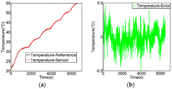
Figure 5.
(a) Comparison of the measurement results of the airflow-temperature sensor with the reference temperature. (b) Measurement error of airflow-temperature sensor.
The schematic diagram of the on-line reinforcement learning control method for the thermal and energy management is shown in Figure 6, where multiple airflow-temperature sensors were distributed to detect the airflow-temperature fields as the environment state in the control system.
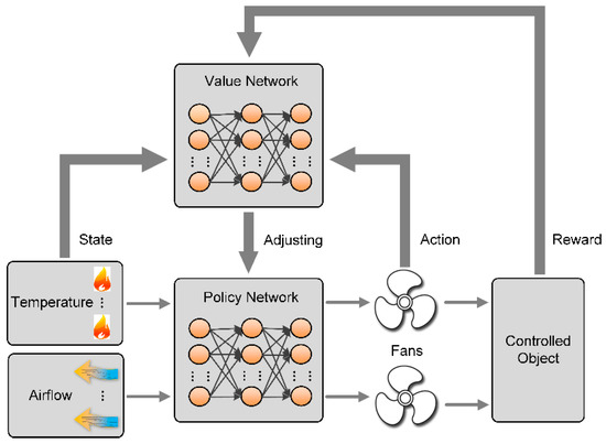
Figure 6.
Schematic diagram of the on-line reinforcement learning control method for the thermal and energy management.
Using the neural network approach mentioned in Section 3, the value network is to evaluate the state and action pair. It maps the environment state and the action to reward. The value network gets a reward from the outputs of the controlled object and updates the network parameters to optimize the evaluation. The policy network exports the control commands to drive cooling fans according to the airflow and the temperature information. The parameters of the policy network are adjusted on the basis of the evaluation of the value network. The selection of the reward function is conducted by considering the accuracy of temperature control and the power consumption of the fans. The reward is formulated as
where P(t + 1) denotes the power consumption of the fans at time t + 1. Ti(t + 1) and Ri(t + 1) denote the sampled and target temperature values of sensor i at time t + 1, respectively. Di represents the requirement of temperature control precision and αi is the factor that regulates the ratio of each control target. P0 and T0 are the basic values of power consumption and temperature respectively.
5. Experiments and Discussion
5.1. Experiment Setup
The proposed control method incorporating bimodal airflow-temperature sensing with reinforcement learning is applied to execute the temperature and energy management in a mockup of a multimodal instrument as seen in Figure 7.
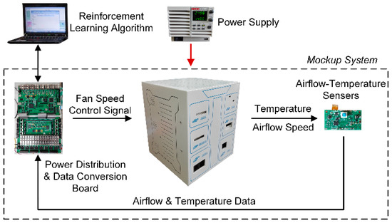
Figure 7.
Schematic diagram of the experiment system.
The configuration of the mockup is shown in Figure 8, which contains six fans (Fan1 to Fan6) and six inside modules (Module1 to Module6). There is a heater in each module. The different module has a different shape, size and heating power. Six cooling fans are installed at the back of the mockup, serving as the actuators to generate airflows inside the mockup. Six airflow-temperature sensors are distributed at the tops of six modules and used to detect the airflow velocities and temperatures in situ. The power distribution and data conversion board supplies power to cooling fans, and acquires the sensor data and transmits them to the computer. The computer executes the reinforcement learning algorithm and exports the control commands. The commands are transmitted through the data conversion board to actuate the cooling fans, formatted as pulse width modulation (PWM) signals.
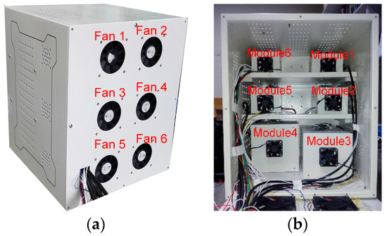
Figure 8.
Mockup of the experiment platform. (a) Side view of the mockup; (b) Internal layout of the mockup.
5.2. Experiment Results and Discussion
Two experiments were conducted. The first experiment was aimed at the selection of the control target. Dual indices of the temperature and energy-saving were considered as the control targets, the results of which are compared with that of only accounting for the temperature as shown in Figure 9. The second experiment aimed at the evaluation on the temperature control by using dual physical fields of airflow and temperature, the results of which are compared with that of using only the temperature sensing as shown in Figure 10.
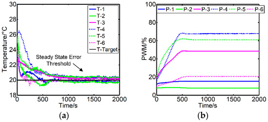
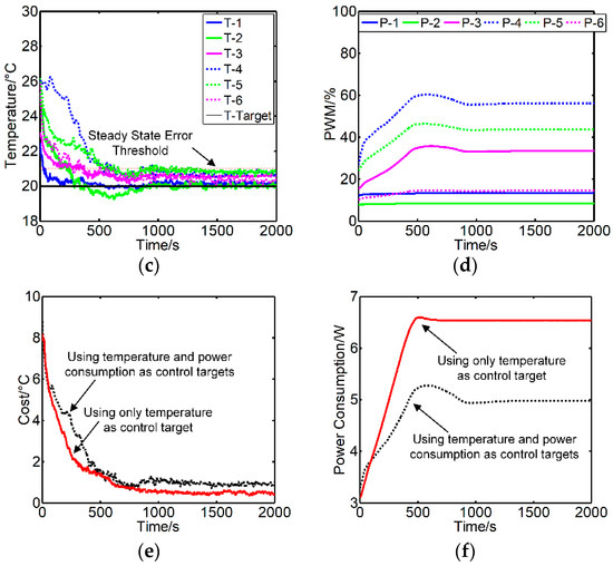
Figure 9.
The control effect comparison when using only temperature as control target and using temperature and power consumption as control targets. (a,b) Temperature and PWM signals when only considering temperature as the target. (c,d) Temperature and PWM signals when considering temperature and power consumption as the targets. (e,f) Cost function and power consumption comparison of the two different target settings.
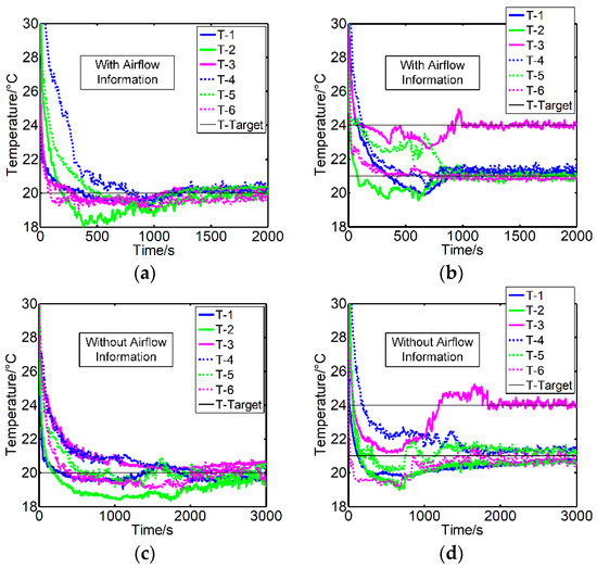
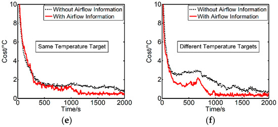
Figure 10.
The control effect comparison when taking temperature only as input and taking airflow speed and temperature as input. (a,b) Temperature signals with airflow information when setting the same or different temperature targets. (c,d) Temperature signals without airflow information when setting the same or different temperature targets. (e,f) Cost function comparison with or without airflow information.
The temperature target was set to 20 °C in the first experiment and the control accuracy was required to be less than 1 °C. The Figure 9a,b show the change curves of temperature and PWM signals when only considering temperature as the target, while Figure 9c,d account for the temperature and energy-saving.
The T1–T6 in the figures denote the temperatures sampled by the sensors placed at Module1 to Module6 separately. T-Target denotes the target temperature. P1–P6 denote the PWM signals sent to Fan1 to Fan6. The fan’s rotate speed increase with the rising of PWM signal’s value. At first, the fans didn’t work, and the sampled temperatures located away from the target temperature. Then the control algorithm started working. The sampled temperatures varied in the predefined target temperature. Due to the different control purposes, the temperature and PWM signals had their own features. The learning rate was set the same and with the purpose of making the system work stably. As shown in Figure 9a,b, when considering the temperature as target only, the temperature signals surrounded the target temperature under a steady state. But when taking into account the temperature and energy-saving as illustrated in Figure 9c,d, although the steady state error increased slightly, the PWM signals were lower, which made less power consumption. An examination of Figure 9c,d revealed that when the temperature and PWM signals moved away from the optimal running state, the PWM signals could be clearly adjusted to make a better result. The temperature control error and power consumption varying curves of the two conditions can be obtained in Figure 9e,f. The duration of response was about 1000 s.
It can be observed that the temperature controls with and without considering energy-saving both satisfied the temperature control requirement, which is less than 1 °C. However, the power consumption could be also controlled by using dual-objectives of temperature and energy-saving. The comparison of the cost function value and power consumption in the two cases is shown in Table 1, where the cost function is formulated as Equation (17).
where e represents the difference between the target and actual temperature, m represents the number of the module, and n represents the sample number.

Table 1.
Comparison of cost function value and power consumption with different control targets.
Figure 10 shows the temperature control results of using only the temperature sensing and using dual physical field information of airflow and temperature. Figure 10a,b were the temperature control performance with airflow information, while Figure 10c,d were without airflow information. These curves could all move toward their targets at last and the duration of response were about 1000 s and 2000 s, respectively. In both settings, it is not hard to see that by using two physical parameters of airflow and temperature as sensing information, the temperature control became more accurate and faster than only sensing the temperature. The airflow information accelerated the temperature control process, shortened the response time and improved control accuracy. The comparison of the cost function values is shown in Table 2.
Table 2.
Comparison of cost function value with different sensing information.
Experiment results demonstrate the advantages of taking dual parameters of airflow and temperature as sensing information and selecting dual-objectives of temperature and energy-saving as the control targets. The aforementioned on-line reinforcement learning method can effectively solve multi-objective control problem, especially for coupling MIMO integrated system.
6. Conclusions
In this paper, we proposed a novel efficient method incorporating bimodal airflow-temperature sensing with the reinforcement learning for fast and accurate thermal and energy management with good robustness and adaptability. The methodology is easily operated by self-learning in no need of controlled object model and human priori experiences. The bimodal airflow-temperature sensing is achieved by a micromachined sensor that can simultaneously detect the dual fields of airflow and temperature, which provides comprehensive information for the reinforcement learning approach of thermal and energy management. The experiment results validate the effectiveness of the proposed control method and demonstrate its superiorities on intelligence, control accuracy, and efficiency. The proposed method can be extended to apply in various systems, such as electronic equipment, energy devices, construction, plug-in hybrid electric vehicle, and data center.
Author Contributions
Z.Z. and C.M. conceived and designed experiments; Z.Z. performed the experiments; Z.Z. and C.M. analyzed the data; C.M. and R.Z. contributed materials and analysis tools; Z.Z. wrote the paper; C.M. and R.Z. revised the manuscript.
Funding
This research was funded by the National Key Scientific Instrument and Equipment Development Projects, China grant number [2013YQ19046705].
Conflicts of Interest
The authors declare no conflict of interest.
References
- Khaleghi, B.; Khamis, A.; Karray, F.O.; Razavi, S.N. Multisensor data fusion: A review of the state-of-the-art. Inf. Fusion 2013, 14, 28–44. [Google Scholar] [CrossRef]
- Azimirad, E.; Haddadnia, J.; Izadipour, A. A Comprehensive Review of the Multi-Sensor Data Fusion Architectures. J. Theor. Appl. Inf. Technol. 2015, 71, 33–42. [Google Scholar]
- Canazza, S.; Foresti, G.L. A Multimodal Learning System for Individuals with Sensorial, Neuropsychological, and Relational Impairments. J. Sens. 2013, 2013, 564864. [Google Scholar] [CrossRef]
- Muensterjohann, S.; Grabinger, J.; Becker, S.; Kaltenbacher, M. CAA of an Air-Cooling System for Electronic Devices. Adv. Acoust. Vibr. 2016, 2016, 4785389. [Google Scholar] [CrossRef]
- Xu, X.M.; He, R. Research on the Heat Dissipation Performance of Battery Pack Based On Forced Air Cooling. J. Power Sources 2013, 240, 33–41. [Google Scholar] [CrossRef]
- Zalba, B.; Marin, J.M.; Cabeza, L.F.; Mehling, H. Free-Cooling of Buildings with Phase Change Materials. Int. J. Refrig. 2004, 27, 839–849. [Google Scholar] [CrossRef]
- Fan, L.; Khodadadi, J.M.; Pesaran, A.A. A Parametric Study on Thermal Management of an Air-Cooled Lithium-Ion Battery Module for Plug-In Hybrid Electric Vehicles. J. Power Sources 2013, 238, 301–312. [Google Scholar] [CrossRef]
- Patankar, S.V. Airflow and Cooling in a Data Center. J. Heat Transf. 2010, 132, 073001. [Google Scholar] [CrossRef]
- Ahrberg, C.D.; Ilic, B.R.; Manz, A.; Neuzil, P. Handheld Real-Time PCR Device. Lab Chip 2016, 16, 586–592. [Google Scholar] [CrossRef] [PubMed]
- Lee, C.; Chen, R. Optimal Self-Tuning PID Controller Based on Low Power Consumption for a Server Fan Cooling System. Sensors 2015, 15, 11685–11700. [Google Scholar] [CrossRef] [PubMed]
- Barros, J.D.S.G.; Rossi, L.A.; Souza, Z.M.D. PID Temperature Controller in Pig Nursery: Spatial Characterization of Thermal Environment. Int. J. Biometeorol. 2017, 62, 773–781. [Google Scholar] [CrossRef] [PubMed]
- Pamela, D.; Premi, M.S.G. Wireless Control and Automation of Hot Air Temperature in Oven for Sterilization using Fuzzy PID Controller and Adaptive Smith Predictor. Wirel. Pers. Commun. 2017, 94, 2055–2064. [Google Scholar] [CrossRef]
- Li, J.Y.; Meng, X.F. Temperature Decoupling Control of Double-Level Air Flow Field Dynamic Vacuum System Based on Neural Network and Prediction Principle. Eng. Appl. Artif. Intell. 2013, 26, 1237–1245. [Google Scholar]
- Gil, P. Affine Neural Network-Based Predictive Control Applied to a Distributed Solar Collector Field. IEEE Trans. Control Syst. Technol. 2014, 22, 585–596. [Google Scholar] [CrossRef]
- Shen, L. Temperature Uniformity Control of Large-Scale Vertical Quench Furnaces for Aluminum Alloy Thermal Treatment. IEEE Trans. Control Syst. Technol. 2016, 24, 24–39. [Google Scholar] [CrossRef]
- Zhang, C.S.; Xu, J.L.; Ma, W.L.; Zheng, W.L. PCR Microfluidic Devices for DNA Amplification. Biotechnol. Adv. 2006, 24, 243–284. [Google Scholar] [CrossRef] [PubMed]
- Li, C.; Li, Z.; Jia, H.; Yan, J. One-Step Ultrasensitive Detection of MicroRNAs with Loop-Mediated Isothermal Amplification (LAMP). Chem. Commun. 2011, 47, 2595–2597. [Google Scholar] [CrossRef] [PubMed]
- Yang, S. A Cell Counting/Sorting System Incorporated with a Microfabricated Flow Cytometer Chip. Meas. Sci. Technol. 2006, 17, 2001–2009. [Google Scholar] [CrossRef]
- Pires, N.M.M.; Dong, T.; Hanke, U.; Hoivik, N. Recent Developments in Optical Detection Technologies in Lab-on-a-Chip Devices for Biosensing Applications. Sensors 2014, 14, 15458–15479. [Google Scholar] [CrossRef] [PubMed]
- Zhang, Z.; Ma, C.; Zhu, R. Self-Tuning Fully-Connected PID Neural Network System for Distributed Temperature Sensing and Control of Instrument with Multi-Modules. Sensors 2016, 16, 1709. [Google Scholar] [CrossRef] [PubMed]
- Tu, Y.D.; Wang, R.Z.; Ge, T.S.; Zheng, X. Comfortable, High-Efficiency Heat Pump with Desiccant-Coated, Water-Sorbing Heat Exchangers. Sci. Rep. 2017, 7, 40437. [Google Scholar] [CrossRef] [PubMed]
- Lillicrap, T.P. Continuous control with deep reinforcement learning. Comput. Sci. 2016, 6, A187. [Google Scholar]
- Mnih, V. Human-Level Control through Deep Reinforcement Learning. Nature 2015, 518, 529–533. [Google Scholar] [CrossRef] [PubMed]
- Silver, D. Mastering the Game of Go with Deep Neural Networks and Tree Search. Nature 2016, 529, 484–489. [Google Scholar] [CrossRef] [PubMed]
- Mnih, V. Playing Atari with deep reinforcement learning. arXiv, 2013; arXiv:1312.5602. [Google Scholar]
- Sutton, R.S.; Barto, A.G. Reinforcement Learning: An Introduction; MIT Press: Cambridge, MA, USA, 1998. [Google Scholar]
- Liu, T. Reinforcement learning—Based energy management strategy for a hybrid electric tracked vehicle. Energies 2015, 8, 7243–7260. [Google Scholar] [CrossRef]
- Mbuwir, B.V. Battery energy management in a microgrid using batch reinforcement learning. Energies 2017, 10, 1846. [Google Scholar] [CrossRef]
- Silver, D. Deterministic policy gradient algorithms. In Proceedings of the 31st International Conference on International Conference on Machine Learning, Beijing, China, 21–26 June 2014. [Google Scholar]
- Que, R.Y.; Zhu, R.; Wei, Q.Z.; Cao, Z. Temperature Compensation for Thermal Anemometers Using Temperature Sensors Independent of Flow Sensors. Meas. Sci. Technol. 2011, 22, 085404. [Google Scholar] [CrossRef]
- Jiang, P.; Zhao, S.; Zhu, R. Smart Sensing Strip Using Monolithically Integrated Flexible Flow Sensor for Noninvasively Monitoring Respiratory Flow. Sensors 2015, 15, 31738–31750. [Google Scholar] [CrossRef] [PubMed]
- Liu, P.; Zhu, R.; Que, R. A Flexible Flow Sensor System and its Characteristics for Fluid Mechanics Measurements. Sensors 2009, 9, 9533–9543. [Google Scholar] [CrossRef] [PubMed]


© 2018 by the authors. Licensee MDPI, Basel, Switzerland. This article is an open access article distributed under the terms and conditions of the Creative Commons Attribution (CC BY) license (http://creativecommons.org/licenses/by/4.0/).