Article

Research on Ultracapacitors in Hybrid Systems: Case Study

by
Piotr Piórkowski
1,*,
Adrian Chmielewski
2,*,
Krzysztof Bogdziński
2,
Jakub Możaryn
3 and
Tomasz Mydłowski
2
1
Institute of Construction Machinery Engineering, Warsaw University of Technology, Narbutta 84 Str., 02-524 Warsaw, Poland
2
Institute of Vehicles, Warsaw University of Technology, Narbutta 84 Str., 02-524 Warsaw, Poland
3
Institute of Automatic Control and Robotics, Warsaw University of Technology, Sw. A. Boboli 8, 02-525 Warsaw, Poland
*
Authors to whom correspondence should be addressed.
Energies 2018, 11(10), 2551; https://doi.org/10.3390/en11102551
Submission received: 17 August 2018 / Revised: 20 September 2018 / Accepted: 21 September 2018 / Published: 25 September 2018
(This article belongs to the Section D: Energy Storage and Application)

Abstract

:
This work is concerned with the use of the engine start module (ESM) ULTRA 31/900/24V ultracapacitor in specific hybrid systems consisting of a photovoltaic (PV) module, battery, and internal combustion engine (ICE). The test bench research on the ESM cooperating with the photovoltaic module to prevent its self-discharge has been tested, analyzed, and discussed. Moreover, the power distribution between electrochemical batteries and the ultracapacitor is shown. The potential application of the ultracapacitor connected with batteries for the start-up of an ICE engine is also presented. Furthermore, we analyze the possible application of the ultracapacitor plus battery system in heavy transport vehicles and buses. The main advantages and disadvantages of the system consisting of an ultracapacitor and a battery is presented along with the problem of self-discharge and the conditions of ultracapacitor and battery cooperation. This work also features the assumptions made for the conducted tests, selected accordingly for nominal current values of typical starter motors available on the market.

1. Introduction

Much attention is presently being given to low-emission and zero-emission technologies based on distributed energy generation devices [1], in particular, renewable energy sources [2,3,4] and hybrid cogeneration systems [3]. The key elements used for the start-up of large-scale cogeneration systems based on internal combustion engines are batteries [5] and ultracapacitors [5,6]. Ultracapacitors and batteries are also used in heavy vehicles with conventional drivetrains [7] as well as in trucks and electric vehicles [8,9,10,11,12]. In the case of batteries, during operation in difficult conditions, i.e., low ambient temperature, their operational parameters significantly decrease [6] because the internal resistance of the battery increases (in particular, the resistance of the electrolyte) and the electromotive force and voltage at the connection points decrease. In such conditions, the mechanical resistance in the internal combustion engine is higher too, which is caused by the higher density of engine oil. This, in conjunction with the decreased available electric power, results in a higher load on the battery, leading to a decrease in its expected lifetime [13].
In order to increase energy and power, start-up batteries of greater capacity or a greater number of batteries connected in parallel are used, which increases costs. One of the possible solutions to this problem is the implementation of a hybrid energy storage method based on the parallel connection [14,15,16,17,18,19,20,21,22,23,24,25,26,27,28,29,30,31,32,33,34,35,36,37,38,39] of a battery and an ultracapacitor.
The article is organized as follows. In Section 2, the application of hybrid energy storage based on the ultracapacitor and battery is presented. Section 3 describes the research on the Engine Start Module (ESM) ULTRA 31/900/24V ultracapacitor in a hybrid system with the battery, external current load, and photovoltaic (PV) module. In Section 4, the potential use of the ultracapacitor to start-up an internal combustion engine (ICE) and the research on this hybrid energy storage solution are analyzed and discussed. In Section 5, the main concluding remarks are given.

2. Application of Hybrid Energy Storage for Combustion Engine Start-Up in Difficult Conditions

The following section focuses on the start-up of a Volkswagen 1.9 TDI 107 BHP internal combustion engine for passenger vehicles. The maximum current peak during cranking is 900 A. In Table 1, the main parameters of the tested engine are given.
During cranking of the combustion engine, the starter motor draws a high current from the battery, with peak values reaching hundreds to even thousands of amperes [5], depending on the displacement of the combustion engine. Figure 1a presents the cranking current signal waveform during start-up of a Volkswagen 1.9 TDI 107 brake horse power (BHP) internal combustion engine.
During cranking, the battery voltage (Figure 1b) dropped to 8.5 V (a drop of 4 V). The engine cranking test was conducted in standard conditions (ambient temperature of 293 K).
The advancement in battery technology has made the start-up of combustion engines in standard operating conditions an easy task, with batteries being cheap, effective, and relatively durable [40]. It is worth pointing out that operation in difficult conditions can occur as well, where the high cranking current causes an overly deep drop in battery voltage, a decrease in the power of the starter motor, and combustion engine start-up difficulties. Examples of such difficult conditions are low ambient temperature, long time gaps between engine operation phases, significant power draw from vehicle onboard electrical appliances (i.e., the dashboard), and in the case of vehicles featuring start–stop systems [13], high frequency of system operation (frequent combustion engine start-ups and short periods of battery charging—dynamic conditions that cause the battery to lose charge at a faster rate, decreasing the usable capacity and durability [40]). Additional drawbacks of batteries are self-discharge and difficulty in detecting the discharge point of the battery (often, full discharge occurs suddenly, with no warning [41]).
According to the scientific literature [42,43,44,45,46,47,48,49,50], the rate of self-discharge can range from 5% to even 30% SOC over one month, depending on the type of battery and storage conditions (i.e., ambient temperature) [51,52,53]. Use of a parallel connection of a battery and ultracapacitor allows for availability of stored energy (see Figure 3a) even if the voltage of the hybrid system drops to a value indicating a discharged battery (equivalent to SOC = 0). The amount of energy stored at that voltage in the ultracapacitor still allows for start-up of an internal combustion engine [5]. This situation may occur for vehicles that are used sporadically or in cold climates (i.e., service and military vehicles) [6] as well as vehicles with an increased load present on the DC electric installation [54,55]. An example of this could be city buses which are required to remain stationary at line endpoints with the engine turned off [56], while a significant power load is still present (i.e., LCD screens, lighting, heating, and air conditioning). It is worth mentioning that the process of self-discharge [9,57] can be limited by addition of PV modules to the system. However, adding PV modules is not always possible (i.e., in vehicles stored in closed garages).
The elimination of the described drawbacks can be achieved by a parallel connection of the battery and the ultracapacitor.

3. Characteristics of Energy Storage Solutions

3.1. General Characteristics of Battery and Ultracapacitor

In the following section, we present the open circuit voltage plots (OCV) as the function of state of charge (SOC) for a battery (Figure 2a) and ultracapacitor (Figure 2b).
In the case of the battery (Figure 2a), the plot features a flat, slightly sloping shape. It is advantageous, considering the amount of the accumulated energy around the operation point, as the amount of energy is maximized. The energy stored in the battery, by definition, is an integral of OCV in respect to accumulated charge Q. Charge Q is proportional to SOC, therefore the energy stored in the battery can be expressed as
E b a t = O C V d Q | S O C = Q Q n o m 1 d Q = Q n o m d S O C = Q n o m O C V d S O C  
At voltage OCV, which is almost constant through the entire range of SOC, the amount of energy stored is almost linear to the increase of SOC value. It is worth noting that OCV changes slightly due to SOC change, and the waveform is flat. As a result, even a small error in OCV measurements results in significant SOC estimation error (dOCV/dSOC ≈ 0 which means dSOC). While estimating OCV during load, the following dependence can be used:
O C V = U R i  
It is worth noting that the error of SOC estimation is significant because no dynamic processes are taken into account, such as voltage relaxation. For more precise OCV estimation methods, such as electrochemical impedance spectroscopy [58] and the Kalman filter [21,59,60,61], which estimate the SOC using the voltage and charge Q measurements simultaneously, charge Q is determined as an integral of load current. Despite the Kalman filter method giving the best SOC estimation results, it is still subject to some error [62].
In the case of the ultracapacitor, the energy stored (Figure 2b) is an integral of OCV in respect to accumulated charge Q. Charge Q is proportional to SOC and the OCV voltage increases almost linearly with SOC increase. Therefore, the energy stored in the ultracapacitor can be approximated as a second power function of SOC. Therefore, the equation for stored energy can be written as
E U C = Q n o m O C V d S O C = Q n o m Q C 1 d S O C Q n o m C 1 S O C Q n o m d S O C = 1 2 S O C 2 Q n o m U n o m = 1 2 S O C 2 C U n o m 2
It should be emphasized that ultracapacitors, in contrast to batteries, store energy even at low voltages (even close to 0 V) [63,64,65,66,67,68]. On the contrary, the amount of energy stored is lower compared to batteries. The increasing shape of OCV = f (SOC) characteristics for an ultracapacitor is beneficial for the possibility of estimating the SOC and assessing the amount of energy stored in the ultracapacitor. In the simplest case, the SOC of the ultracapacitor is estimated based on OCV measurement and knowledge of function OCV = f (SOC), presented in Figure 2a. The OCV changes significantly with SOC change. Therefore, even a significant OCV measurement error does not result in a notable error in SOC estimation, which can be written as
d O C V / d S O C U n o m d O C V U n o m d S O C  
As with the battery, the OCV can be estimated during load using Equation (3). It is worth remembering that the SOC estimation error is significant because dynamic processes are taken into consideration, such as voltage relaxation. More accurate SOC estimation (even during load) can be achieved through tools, such as various combinations of the Kalman Filter [21,59,60,61] and other prediction methods [69] based on recurrent neural networks [41,70].

3.2. Hybrid Energy Storage Based on Battery and Ultracapacitor

Properties of ultracapacitors and batteries are often complementary to each other. It can be seen especially when a parallel connection of the two components into a system that combines the benefits of both energy storage solutions can be achieved. In particular, the parallel configuration of ultracapacitors and batteries will simultaneously have high energy (effect of batteries) and high power (effect of ultracapacitors) [5,11], even at very low ambient temperatures (effect of ultracapacitors) and at a low SOC. Figure 3a shows relationships between energy stored in the battery, ultracapacitor, and ultracapacitor–battery system as a function of voltage.
These plots clearly present the benefits of the parallel connection of the aforementioned elements. On the one hand, the system offers high amounts of energy in the higher voltage range (provided by the battery); on the other hand, it stores energy even at low voltages (effect of the ultracapacitor). For the accordingly large capacity of the ultracapacitor, the amount of energy it stores can be sufficient for combustion engine start-up [5], even with a discharged battery (that is, at very low voltages of the system). Discharge of the battery can be caused by low ambient temperature or power draw from onboard electrical appliances and devices.
Figure 3b presents the relationship between the OCV of the ultracapacitor–battery system and its SOC. This characteristic shows another benefit resulting from the parallel connection of those elements—a strong curvature of the waveform at the low SOC range. This shape indicates that low SOC causes a faster and more visible OCV drop in comparison to the battery. The state of approaching the full discharge can be detected earlier and with greater certainty, without the risk of a sudden lack of the required power.
Currently available on the market are single ultracapacitor cells and modules with the serial or serial-parallel connection of several cells. Modules are equipped with electronic control systems, such as a battery management system (BMS), that ensure an equal charge level in all cells and overcharge protection. With such a module, parallel connection with batteries is relatively simple if the required “soft start” system for limiting the amount of current equalizing the voltages at the moment of connection of a discharged ultracapacitor with the battery is kept in mind. To ensure protection against deep discharge of the batteries, a DC/DC converter [17,36,37,39] is required for raising the ultracapacitor output voltage to a level safe for the battery.
Ultracapacitor modules featuring these kinds of electronic systems (BMS, “soft start”, and DC/DC converter) in a single case are similar in size to a starter battery and are available on the market in 24 V versions (such as the ESM, manufactured by Maxwell [7]). The research results of this hybrid configuration are presented in Section 4.

4. Description of the Test Stand and Research on Hybrid Energy Storage

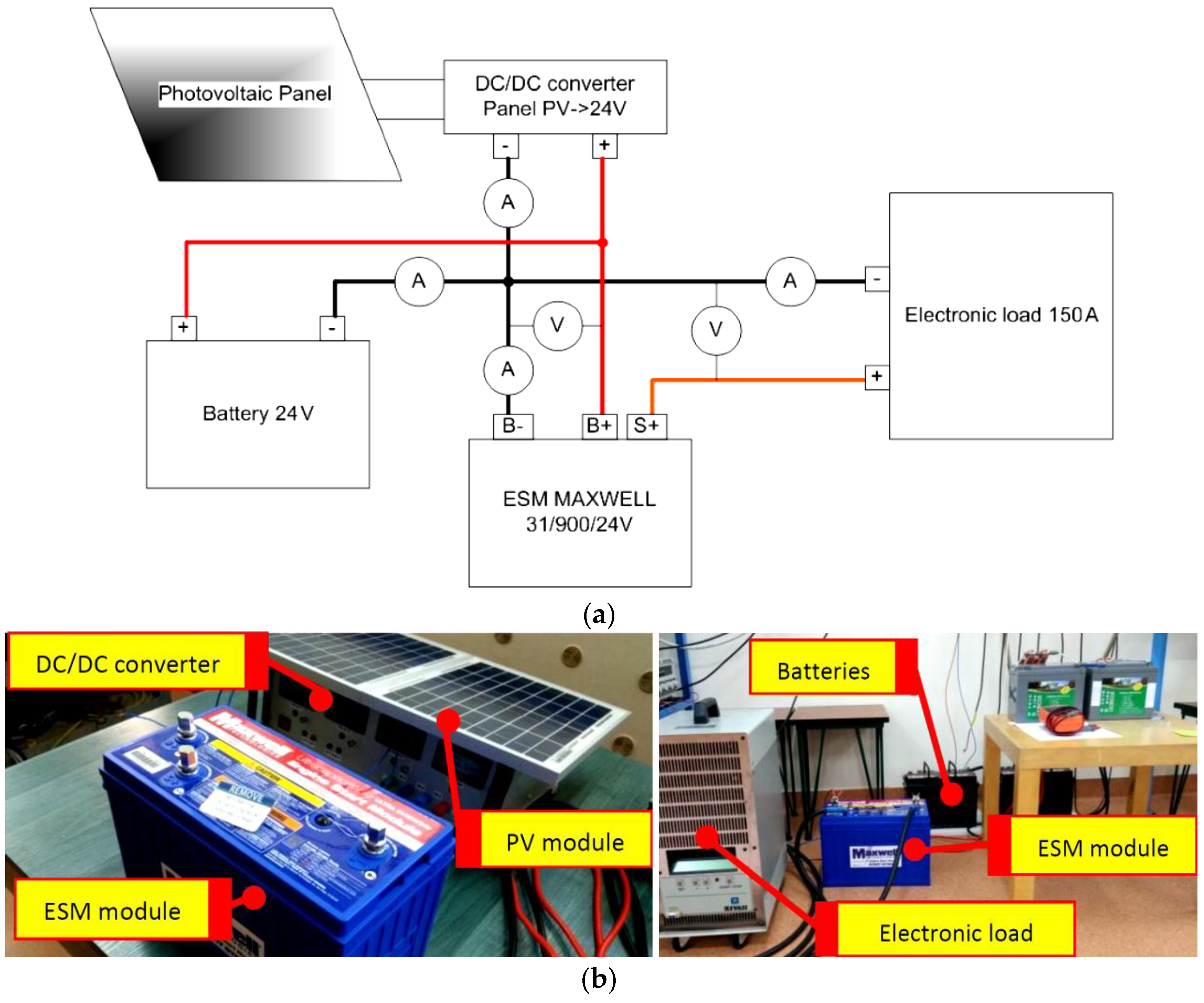
4.1. Test Stand—Hybrid Energy Storage

In the following section, a diagram of the stand is presented (Figure 4a) and there are photographs shown of the hybrid energy storage solution (Figure 4b) based on an ultracapacitor and battery. The ESM, manufactured by Maxwell (version ESM ULTRA 31/900/24V), was connected with a 24 V battery (two 12 V and 80 Ah batteries, connected in series) and a programmable electronic load that was capable of creating a current load of up to 150 A.
The presented system is dedicated for use in trucks, buses, and other heavy vehicles, which in Europe commonly feature a 24 VDC [71] electric installation instead of 12 VDC used in passenger vehicles. In other regions, e.g., Australia, commercial heavy vehicles may feature a 12 VDC electric installation [72,73]. The system is supposed to provide conditions for a trouble-free start-up of heavy vehicle engines (such as trucks, special service vehicles, military vehicles, etc.) and city buses used in specific conditions. These conditions occur very rarely in operation of passenger vehicles (featuring a 12 VDC electric installation). Furthermore, a 12 VDC variant of the system was not considered, as it would be expensive to implement in heavy-duty vehicles [72].
In the test presented in Figure 1a, the peak value of the start-up current (current peak of about 900 A) occurs briefly at the very beginning of the start-up process, when the starter motor is still stationary or is already rotating at a very low speed. This indicates a condition close to a short-circuit of the starter motor. The starter motor that has reached a nominal rotational speed exerts a current load on the battery of the nominal value, much less than the current value of a shorted circuit. Based on the subject literature [5], the time of engine start-up in difficult conditions may reach several to several dozen seconds. During this time, the starter motor rotates at nominal speed until the combustion engine starts. The current value of 150 A shown in Figure 7a,b represents a nominal current value typical for starter motors [74].
Time of start-up of about 1 s represents engine start-up in typical conditions with use of a well-charged battery. However, in certain conditions, i.e., in low temperatures or if the vehicle has not been started for a long period of time and the self-discharge causes a drop in voltage of the DC installation, the start-up may occur after several attempts, and the total time of start-up may reach several dozen seconds. Hence, the test conditions presented in Figure 7a,b.
The test presented in Figure 5 shows charging of the ultracapacitor with energy from the battery and PV module. Before start-up of the combustion engine, the ultracapacitor has to be charged. An assumption was made here that the battery was already mostly discharged while connecting the ultracapacitor and thus it could not be loaded with high currents. This is the reason for the gently increasing the current charge profile from 0 to about 8 A over at least 1000 s.
Various standards describe methods of start-up battery testing [75,76,77], which show that the discharging current is constant or periodically constant and is a given multiple of the nominal current. The load current is applied until the state of charge of the battery drops from 100% SOC to a desired level (i.e., 50% SOC).
The stand was equipped with: four current sensors for the battery, ESM module, photovoltaic panel, and electronic load; two voltage sensors for the battery and ESM module; and a measurement data acquisition system. The stand was completed with a photovoltaic panel (connected through a step-down DC/DC converter), the purpose of which was to supply electricity to compensate the natural effect of self-discharge in the battery and ultracapacitor. The photovoltaic panel was not required for the system to operate, but it expanded its functionality.
The external dimensions of the ESM ULTRA 31/900/24V ultracapacitor module meet the standards for BCI Group 31 start-up batteries (330 mm L × 173 mm W × 240 mm H) [7,78], which allows placing the module inside spaces dedicated for vehicle batteries. The mass of the ESM ULTRA 31/900/24V module is only 7.3 kg. Often, in trucks and buses, several batteries can be used in a parallel and/or series configuration to achieve sufficient power for start-up. Exchanging one of the batteries with the ESM ULTRA 31/900/24V module allows for achieving higher start-up power while lowering the weight of the system without increasing the volume of the system.

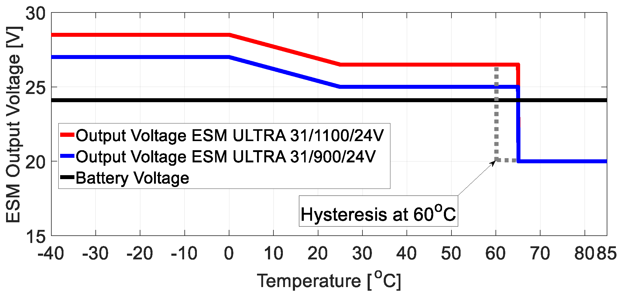
4.2. Results of Test Stand Research

In the following section, the results of research conducted on the test stand are presented. The ultracapacitor ESM module was charged from the battery with a low-value current that was gradually increased from 0 to 8 A (Figure 5). The charge current was controlled by a DC/DC buck-boost-type converter built into the ESM module. The time of charging ranged from 15 to 20 m, until the desired voltage between B− and S+ terminals of the ESM was reached (during the test, the value was 25 V). The desired output voltage value of the ESM was automatically controlled and was dependent on ambient temperature according to the characteristics presented in Figure 6. The lower the ambient temperature, the higher the ESM output voltage grew, which was meant to compensate for the increase of internal resistance and the voltage drop associated with it.
Based on the analysis of Figure 5, it can be concluded that the current required to charge the ESM module was drawn mainly from the battery but also partly from the photovoltaic panel (in time range 920–1090 s). The main purpose of the photovoltaic panel was to prevent self-discharge of the battery and ESM module.
In Figure 7a,b, the plots of the battery and ultracapacitor ESM module voltage are presented, as well as load current during the heavy load test of the ESM. In the test presented in Figure 7a, the ESM module was fully charged at the beginning, while for the test shown in Figure 7b, the ESM module was partially discharged at the beginning (to about 40% SOC). The load test consisted of discharging the ESM with 150 A current during several-second intervals.
Intensive, several-second discharging caused a gradual decrease of voltage on the terminals of the ESM module, as low as one-fifth of the initial voltage. Despite the gradual decrease of voltage from 25 to 6 V, the module reliably delivered the desired current of 150 A. At the same time, the battery voltage was stable, at a value of around 24.5 V, since only a current of about 8 A (used to charge the ESM module) was drawn from it.

5. Conclusions

The experiments have shown that the ultracapacitor start-up module ESM ULTRA 31/900/24V can be extensively loaded with high current values for several-second intervals, similar to conditions during start-up cranking of high-displacement internal combustion engines.
The extensive load can be applied almost to complete discharge of the ESM module (practically to the voltage of 0 V). High voltage changes help to estimate the state of charge of the ultracapacitor module and prevent the risk of a sudden loss of power of the starter motor. The voltage drop of the ESM module below a certain level can be used as a trigger signal to initialize the combustion engine start-up and start of battery charging.
The proposed addition of a photovoltaic panel reduces the load on the battery during ESM charging, but most importantly, it prevents the system from the self-discharge during long nonoperational periods, where it performs the “stand-by” function in the system.
During operation, only a small amount of current (several amperes) is drawn from the battery, which greatly extends the durability, lifetime, and usable capacity of the battery. Low current draw from the battery allows the system to operate in states of significant battery discharge. Therefore, the system can provide power over a long time to the electric installation, such as the vehicle onboard electronics (from the battery, with the nonoperating combustion engine), without the risk of combustion engine start-up difficulties. A reliable start-up is ensured by the ultracapacitor ESM module.
It is worth emphasizing that the ESM module can be used either for the start-up of large gas engines or cogeneration systems. The parallel connection of the battery and the ESM module increases the energy of the energy storage as well as its power density. The solution presented in this work can be implemented as a start-up solution for other types of distributed generation systems [1] as well as vehicles such as trucks, special service vehicles, military vehicles, and city buses operating in particular environmental conditions. The research presented in the paper was conducted according to assumptions of cooperation of the elements of the PV module plus battery and ultracapacitor system for an external load of 150 A, which corresponds to the nominal value of current for typical heavy vehicle starter motors found on the European market [71] that are equipped with a 24 VDC electric installation. The paper also highlights the main advantages of an ultracapacitor plus battery system, such as:
  • A greater power density of the hybrid system in comparison to a battery-only system.
  • The energy is available in a wider range (ultracapacitor effect). So, even if the battery is completely discharged (SOC = 0), the ultracapacitor can still deliver energy to the starter motor system, which allows for engine start-up, especially in difficult conditions (such as low ambient temperature, infrequent start-up, very high momentary current peaks, etc.).
  • The reduction of costs related to the replacement of the battery (extension of the battery lifetime). In the considered system, the ultracapacitor takes over the larger part of the load, which means the battery is not loaded with high current values (maximal current values are not exceeded), which directly influences the extension of the battery lifetime [40].
    A disadvantage of this system is:
  • Self-discharge. For the battery, the rate of self-discharge ranges from about 5% up to even 30% SOC over a one-month period depending on the type of battery and the storage conditions (e.g., ambient temperature). In the case of the ultracapacitor, the rate of self-discharge is about 6.25% per month (75% per year) [53].

Author Contributions

Conceptualization, P.P.; Data curation, P.P. and A.C.; Formal analysis, P.P. and A.C.; Investigation, P.P.; Methodology, P.P.; Software, A.C.; Supervision, P.P.; Visualization, T.M.; Writing—original draft, P.P., A.C., and K.B.; Writing—review & editing, P.P., A.C., and J.M.

Funding

“This research has not received any specific grant from funding agencies in the public, commercial, or not-for-profit sectors, but it has been performed as part of the employment of the authors at the Institute of Construction Machinery Engineering, Institute of Vehicles and Institute of Automatic Control and Robotics, Warsaw University of Technology.” The APC was co-funded by Institute of Construction Machinery Engineering, Institute of Vehicles and Institute of Automatic Control and Robotics, Warsaw University of Technology.

Conflicts of Interest

The authors declare no conflict of interest.

References

  1. Chmielewski, A.; Gumiński, R.; Mączak, J.; Radkowski, S.; Szulim, P. Aspects of balanced development of RES and distributed micro cogeneration use in Poland: Case study of a µCHP with Stirling engine. Renew. Sustain. Energy Rev. 2016, 60, 930–952. [Google Scholar] [CrossRef]
  2. Chia, Y.Y.; Lee, L.H.; Shafiabady, N.; Isa, D. A load predictive energy management system for supercapacitor-battery hybrid energy storage system in solar application using the Support Vector Machine. Appl. Energy 2015, 137, 588–602. [Google Scholar] [CrossRef]
  3. Chmielewski, A.; Możaryn, J.; Bogdziński, K.; Piórkowski, P.; Mydłowski, T.; Gumiński, R.; Mączak, J. Selected properties of the hybrid micro–installation model based on electrochemical battery and PV module. Int. J. Struct. Stab. Dyn. 2018, in press. [Google Scholar]
  4. Mellit, A.; Kalogirou, S.A. Artificial intelligence techniques for photovoltaic applications: A review. Prog. Energy Combust. Sci. 2008, 34, 574–632. [Google Scholar] [CrossRef]
  5. Jankowska, E.; Kopciuch, K.; Błażejczyk, M.; Majchrzycki, W.; Piórkowski, P.; Chmielewski, A.; Bogdziński, K. Hybrid energy storage based on ultracapacitor and lead acid battery: Case study. In Automation 2018: Advances in Intelligent Systems and Computing; Szewczyk, R., Zieliński, C., Kaliczyńska, M., Eds.; Springer: Cham, Switzerland, 2018; Volume 743, pp. 339–349. [Google Scholar]
  6. Piórkowski, P. Zastosowanie superkondensatorów do rozruchu silników spalinowych w trudnych warunkach (Application of supercapacitors to start combustion engines in tough conditions). Logistyka 2015, 3, 3918–3927. (In Polish) [Google Scholar]
  7. Maxwell Technologies. Maxwell’s Ultracapacitor-Based Engine Start Module. Available online: http://www.maxwell.com/esm/ (accessed on 4 August 2018).
  8. Hannan, M.A.; Lipu, M.S.H.; Hussain, A.; Mohamed, A. A review of lithium-ion battery state of charge estimation and management system in electric vehicle applications: Challenges and recommendations. Renew. Sustain. Energy Rev. 2017, 78, 834–854. [Google Scholar] [CrossRef]
  9. Chmielewski, A.; Szulim, P.; Gregorczyk, M.; Gumiński, R.; Mydłowski, T.; Mączak, J. Model of an electric vehicle powered by a PV cell—A case study. In Proceedings of the 2017 22nd International Conference on Methods and Models in Automation and Robotics (MMAR), Miedzyzdroje, Poland, 28–31 August 2017. [Google Scholar]
  10. Szumanowski, A.; Piórkowski, P.; Chang, Y. Batteries and ultracapacitors set in hybrid propulsion system. In Proceedings of the 2007 International Conference on Power Engineering, Energy and Electrical Drives, Setubal, Portugal, 12–14 April 2007. [Google Scholar]
  11. Chmielewski, A.; Piórkowski, P.; Bogdziński, K.; Szulim, P.; Gumiński, R. Test bench and model research of hybrid energy storage. J. Power Technol. 2017, 97, 406–415. [Google Scholar]
  12. Pavkovi, D.; Cipek, M.; Hrgeti, M.; Mance, M. DC bus feed-forward/feedback control for EVs with battery/ultracapacitor energy storage system. In Proceedings of the IEEE EUROCON 2017—17th International Conference on Smart Technologies, Ohrid, Macedonia, 6–8 July 2017. [Google Scholar]
  13. Lee, C.-H.; Hsu, S.-H. Prediction of equivalent-circuit parameters for double-layer capacitors module. IEEE Trans. Energy Convers. 2013, 28, 913–920. [Google Scholar] [CrossRef]
  14. Fathima, A.H.; Palanisamy, K. Optimization in microgrids with hybrid energy systems—A review. Renew. Sustain. Energy Rev. 2015, 45, 431–446. [Google Scholar] [CrossRef]
  15. Zheng, R.; Cai, R.; Li, M. An on-line active energy flow split strategy for battery-ultracapacitor energized PMSM driving system. In Proceedings of the IECON 2016—42nd Annual Conference of the IEEE Industrial Electronics Society, Florence, Italy, 23–26 October 2016. [Google Scholar]
  16. Ruba, M.; Ciornei, S.; Hodesiu, H.; Martis, C. Complete FPGA based real-time motor drive simulator with bidirectional battery and ultracapacitor power supply. In Proceedings of the 2017 10th International Symposium on Advanced Topics in Electrical Engineering (ATEE), Bucharest, Romania, 23–25 March 2017. [Google Scholar]
  17. Mirzaei, A.; Jusoh, A.; Salam, Z.; Adib, E.; Farzanehfard, H. Analysis and design of a high efficiency bidirectional DC-DC converter for battery and ultracapacitor applications. Simul. Model. Pract. Theory 2011, 19, 1651–1667. [Google Scholar] [CrossRef]
  18. Kuperman, A.; Aharon, I.; Kara, A.; Malki, S. A frequency domain approach to analyzing passive battery-ultracapacitor hybrids supplying periodic pulsed current loads. Energy Convers. Manag. 2011, 52, 3433–3438. [Google Scholar] [CrossRef]
  19. Marzougui, H.; Amari, M.; Kadri, A.; Bacha, F.; Ghouili, J. Energy management of fuel cell/battery/ultracapacitor in electrical hybrid vehicle. Int. J. Hydrog. Energy 2017, 42, 8857–8869. [Google Scholar] [CrossRef]
  20. Henson, W. Optimal battery/ultracapacitor storage combination. J. Power Sources 2008, 179, 417–423. [Google Scholar] [CrossRef]
  21. Hredzak, B.; Agelidis, V.G.; Demetriades, G. Application of explicit model predictive control to a hybrid battery-ultracapacitor power source. J. Power Sources 2015, 227, 84–94. [Google Scholar] [CrossRef]
  22. Kuperman, A.; Aharon, I. Battery-ultracapacitor hybrids for pulsed current loads: A review. Renew. Sustain. Energy Rev. 2011, 15, 981–992. [Google Scholar] [CrossRef]
  23. Atmaja, T.D.; Amin. Energy storage system using battery and ultracapacitor on mobile charging station for electric vehicle. Energy Procedia 2015, 68, 429–437. [Google Scholar] [CrossRef]
  24. Zhou, H.; Bhattacharya, T.; Tran, D.; Siew, T.S.T.; Khambadkone, A.M. Composite energy storage system involving battery and ultracapacitor with dynamic energy management in microgrid applications. IEEE Trans. Power Electron. 2011, 26, 923–930. [Google Scholar] [CrossRef]
  25. Patankar, M.M.; Wandhare, R.G.; Agarwal, V. A high performance power supply for an electric vehicle with solar PV, battery and ultracapacitor support for extended range and enhanced dynamic response. In Proceedings of the 2014 IEEE 40th Photovoltaic Specialist Conference (PVSC), Denver, CO, USA, 8–13 June 2014. [Google Scholar]
  26. Mandla, E.; Mandic, G.; Nasiri, A. Development of an electrical model for lithium–ion ultracapacitors. IEEE J. Emerg. Sel. Top. Power Electron. 2015, 3, 395–404. [Google Scholar] [CrossRef]
  27. Michalczuk, M.; Grzesiak, L.M.; Ufnalski, B. Experimental parameter identification of battery-ultracapacitor energy storage system. In Proceedings of the 2015 IEEE 24th International Symposium on Industrial Electronics (ISIE), Buzios, Brazil, 3–5 June 2015. [Google Scholar]
  28. García, X.d.T.; de la Cruz, C.; Roncero-Sánchez, P.; Parreño, A. A small-scale hybrid energy storage system for modeling and control validation purposes. In Proceedings of the IECON 2015—41st Annual Conference of the IEEE Industrial Electronics Society, Yokohama, Japan, 9–12 November 2015. [Google Scholar]
  29. Jayalakshmi, N.S.; Gaonkar, D.N.; Vikash, K.J.; Karthik, R.P. Battery-Ultracapacitor storage devices to mitigate power fluctuations for grid connected PV system. In Proceedings of the 2015 Annual IEEE India Conference (INDICON), New Delhi, India, 17–20 December 2015. [Google Scholar]
  30. Jing, W.; Lai, C.H.; Wong, S.H.W.; Wong, M.L.D. Battery-Supercapacitor hybrid energy storage system in standalone DC microgrids: A review. IET Renew. Power Gener. 2017, 11, 461–469. [Google Scholar] [CrossRef]
  31. Ostadi, A.; Kazerani, M. A comparative analysis of optimal sizing of battery-only, ultracapacitor-only, and battery–ultracapacitor hybrid energy storage systems for a city bus. IEEE Trans. Veh. Technol. 2015, 64, 4449–4460. [Google Scholar] [CrossRef]
  32. Miller, J.; Schneuwly, A. White paper: Power Electronic Interface for an Ultracapacitor as the Power Buffer in a Hybrid Electric Energy Storage System. Available online: http://www.maxwell.com/images/documents/whitepaper_powerelectronicsinterface.pdf (accessed on 25 July 2018).
  33. Stienecker, A.W.; Stuart, T.; Ashtiani, C. A Combined ultracapacitor-lead acid battery energy storage system for mild hybrid electric vehicles. In Proceedings of the 2005 IEEE Vehicle Power and Propulsion Conference, Chicago, IL, USA, 7–9 September 2005. [Google Scholar]
  34. Basiden, A.C.; Emadi, A. ADVISOR-Based model of battery and an ultra-capacitor energy source for hybrid electric vehicles. IEEE Trans. Veh. Technol. 2004, 53, 199–205. [Google Scholar] [CrossRef]
  35. Ismail, N.M.; Mishra, M.K. Control and operation of unified power quality conditioner with battery-ultracapacitor energy storage system. In Proceedings of the 2014 IEEE International Conference on Power Electronics, Drives and Energy Systems (PEDES), Mumbai, India, 16–19 December 2014. [Google Scholar]
  36. Guo, F.; Ye, Y.; Sharma, R. A Modular multilevel converter based battery-ultracapacitor hybrid energy storage system for photovoltaic applications. In Proceedings of the 2015 Clemson University Power Systems Conference (PSC), Clemson, SC, USA, 10–13 March 2015. [Google Scholar]
  37. Guo, F.; Sharma, R. A modular multilevel converter with half-bridge submodules for hybrid energy storage systems integrating battery and ultracapacitor. In Proceedings of the 2015 IEEE Applied Power Electronics Conference and Exposition (APEC), Charlotte, NC, USA, 15–19 March 2015. [Google Scholar]
  38. Gu, R.; Malysz, P.; Emadi, A. A novel battery/ultracapacitor hybrid energy storage system analysis based on physics-based lithium-ion battery modeling. In Proceedings of the 2015 IEEE Transportation Electrification Conference and Expo (ITEC), Dearborn, MI, USA, 14–17 June 2015. [Google Scholar]
  39. Guidi, G.; Undeland, T.M.; Hori, Y. An interface converter with reduced VA ratings for battery-supercapacitor mixed systems. In Proceedings of the 2007 Power Conversion Conference, Nagoya, Japan, 2–5 April 2007. [Google Scholar]
  40. Chmielewski, A.; Bogdziński, K.; Gumiński, R.; Szulim, P.; Piórkowski, P.; Możaryn, J.; Mączak, J. Operational Research of VRLA Battery. In Automation 2018: Advances in Intelligent Systems and Computing; Szewczyk, R., Zieliński, C., Kaliczyńska, M., Eds.; Springer: Cham, Switzerland, 2018; Volume 743, pp. 783–791. [Google Scholar]
  41. Możaryn, J.; Chmielewski, A. Selected parameters prediction of energy storage system using recurrent neural networks. In Proceedings of the 10th IFAC Symposium on Fault Detection, Supervision and Safety for Techn. Proc.—SAFEPROCESS, Warsaw, Poland; IFAC-PapersOnLine 2018; Elsevier: New York, NY, USA, 2018; in press. [Google Scholar]
  42. Johnson, B.A.; White, R.E. Characterization of commercially available lithium-ion batteries. J. Power Sources 1998, 70, 48–54. [Google Scholar] [CrossRef]
  43. Dürr, M.; Cruden, A.; Gair, S.; McDonald, J.R. Dynamic model of a lead acid battery for use in a domestic fuel cell system. J. Power Sources 2006, 161, 1400–1411. [Google Scholar] [CrossRef]
  44. Simpson, C. Characteristics of Rechargeable Batteries. Available online: http://www.ti.com/lit/an/snva533/snva533.pdf (accessed on 23 July 2018).
  45. Li, W.; Pang, Y.; Zhu, T.; Wang, Y.; Xia, Y. A gel polymer electrolyte based lithium-sulfur battery with low self-discharge. Solid State Ion. 2018, 318, 82–87. [Google Scholar] [CrossRef]
  46. Wang, L.; He, Y.-B.; Shen, L.; Lei, D.; Ma, J.; Ye, H.; Shi, K.; Li, B.; Kang, F. Ultra-small self-discharge and stable lithium-sulfur batteries achieved by synergetic effects of multicomponent sandwich-type composite interlayer. Nano Energy 2018, 50, 367–375. [Google Scholar] [CrossRef]
  47. Knap, V.; Stroe, D.-I.; Swierczynski, M.; Purkayastha, R.; Propp, K.; Teodorescu, R.; Schaltz, E. A self-discharge model of lithium-sulfur batteries based on direct shuttle current measurement. J. Power Sources 2016, 336, 325–331. [Google Scholar] [CrossRef]
  48. Wang, Y.; Qiao, X.; Zhang, C.; Zhou, X. Self-discharge of a hybrid supercapacitor with incorporated galvanic cell components. Energy 2018, 159, 1035–1045. [Google Scholar] [CrossRef]
  49. AI-Mahmoud, S.M.; Dibden, J.W.; Owen, J.R.; Denuault, G.; Garcia-Araez, N. A simple, experiment-based model of the initial self-discharge of lithium-sulphur batteries. J. Power Sources 2016, 306, 323–328. [Google Scholar] [CrossRef] [Green Version]
  50. Zhu, W.H.; Zhu, Y.; Tatarchuk, B.J. Self-discharge characteristics and performance degradation of Ni-MH batteries for storage applications. Int. J. Hydrog. Energy 2014, 39, 19789–19798. [Google Scholar] [CrossRef]
  51. Sun, S.; Guan, T.; Shen, B.; Leng, K.; Gao, Y.; Cheng, X.; Yin, G. Changes of degradation mechanisms of LiFePO4/graphite batteries cycled at different ambient temperatures. Electrochim. Acta 2017, 237, 248–258. [Google Scholar] [CrossRef]
  52. Demircalı, A.; Sergeant, P.; Koroglu, S.; Kesler, S.; Öztürk, E.; Tumbek, M. Influence of the temperature on energy management in battery-ultracapacitor electric vehicles. J. Clean. Prod. 2018, 176, 716–725. [Google Scholar] [CrossRef]
  53. Kowal, J.; Avaroglu, E.; Chamekh, F.; Šenfelds, A.; Thien, T.; Wijaya, D.; Sauer, D.U. Detailed analysis of the self-discharge of supercapacitors. J. Power Sources 2011, 196, 573–579. [Google Scholar] [CrossRef]
  54. Reddy, K.J.; Natarajan, S. Energy sources and multi-input DC-DC converters used in hybrid electric vehicle applications—A review. Int. J. Hydrog. Energy 2018, 43, 17387–17408. [Google Scholar] [CrossRef]
  55. Blasius, E.; Wang, Z. Effects of charging battery electric vehicles on local grid regarding standardized load profile in administration sector. Appl. Energy 2018, 224, 330–339. [Google Scholar] [CrossRef]
  56. The Act on Road Traffic in Poland. Available online: https://prawooruchudrogowym.pl/ (accessed on 12 September 2018). (In Polish).
  57. Matam, M.; Barry, V.R. Improved performance of Dynamic Photovoltaic Array under repeating shade conditions. Energy Convers. Manag. 2018, 168, 639–650. [Google Scholar] [CrossRef]
  58. Buller, S.; Karden, E.; Kok, D.; De Doncker, R.W. Modeling the dynamic behavior of supercapacitors using impedance spectroscopy. IEEE Trans. Ind. Appl. 2002, 38, 1622–1626. [Google Scholar] [CrossRef]
  59. Ramadan, H.S.; Becherif, M.; Claude, F. Extended Kalman filter for accurate state of charge estimation of lithium-based batteries: A comparative analysis. Int. J. Hydrog. Energy 2017, 42, 29033–29046. [Google Scholar] [CrossRef]
  60. Mohamed, A.H.; Schwarz, K.P. Adaptive Kalman filtering for INS/GPS. J. Geod. 1999, 73, 193–203. [Google Scholar] [CrossRef]
  61. He, H.; Xiong, R.; Zhang, X.; Sun, F.; Fan, J.X. State-of-Charge estimation of the lithium-ion, battery using an adaptive extended Kalman filter based on an improved Thevenin model. IEEE Trans. Veh. Technol. 2011, 60, 1461–1469. [Google Scholar]
  62. Chmielewski, A.; Piórkowski, P.; Gumiński, R.; Bogdziński, K.; Możaryn, J. Model-based Research on Ultracapacitors. In Automation 2018: Advances in Intelligent Systems and Computing; Szewczyk, R., Zieliński, C., Kaliczyńska, M., Eds.; Springer: Cham, Switzerland, 2018; Volume 743, pp. 254–264. [Google Scholar]
  63. Zou, C.; Hu, X.; Wei, Z.; Tang, X. Electrothermal dynamics-conscious lithium-ion battery cell-level charging management via state-monitored predictive control. Energy 2017, 141, 250–259. [Google Scholar] [CrossRef]
  64. Goh, C.T.; Cruden, A. Automated high current cycling test system for supercapacitor characterisation. In Proceedings of the 2012 International Symposium on Power Electronics, Electrical Drives, Automation and Motion, Sorrento, Italy, 20–22 June 2012. [Google Scholar]
  65. Mahon, P.J.; Paul, G.L.; Keshishian, S.M.; Vassallo, A.M. Measurement and modelling of the high-power performance of carbon-based supercapacitors. J. Power Sources 2000, 91, 68–76. [Google Scholar] [CrossRef]
  66. Rafik, F.; Gualous, H.; Gallay, R.; Crausaz, A.; Berthon, A. Frequency, thermal and voltage supercapacitor characterization and modeling. J. Power Sources 2007, 165, 928–934. [Google Scholar] [CrossRef]
  67. Nikolov, G.T. High current source-measure unit based on low cost DAQ. In Proceedings of the Electronics’ 2008, Sozopol, Bulgaria, 24–26 September 2008. [Google Scholar]
  68. Cheng, Z.; Chen, W.; Li, Q.; Jiang, Z.; Yang, Z. Modeling and dynamic simulation of an efficient energy storage component- supercapacitor. In Proceedings of the 2010 Asia-Pacific Power and Energy Engineering Conference, Chengdu, China, 28–31 March 2010. [Google Scholar]
  69. Mu, H.; Xiong, R.; Zheng, H.; Chang, Y.; Chen, Z. A novel fractional order model based state-of-charge estimation method for lithium-ion battery. Appl. Energy 2017, 207, 384–393. [Google Scholar] [CrossRef]
  70. Chmielewski, A.; Możaryn, J.; Piórkowski, P.; Gumiński, R.; Bogdziński, K. Modelling of Ultracapacitors Using Recurrent Artificial Neural Network. In Automation 2018: Advances in Intelligent Systems and Computing; Szewczyk, R., Zieliński, C., Kaliczyńska, M., Eds.; Springer: Cham, Switzerland, 2018. [Google Scholar]
  71. Directives and Regulations on Motor Vehicles, Their Trailers, Systems and Components. Available online: https://ec.europa.eu/growth/sectors/automotive/legislation/motor-vehicles-trailers_en (accessed on 13 September 2018).
  72. ATA Industry Technical Council. Heavy Vehicle Electrical Wiring—Technical Advisory Procedure, 2nd ed.; Australian Tracking Association: Forrest, Australia, 2015; Available online: https://www.truck.net.au/system/files/industry-resources/TAPS%20-%20heavy%20vehicle%20electrical%20wiring%20final_0_0.pdf (accessed on 23 September 2018).
  73. Australian Government, Department of Infrastructure, Regional Development and Cities. Available online: https://infrastructure.gov.au/vehicles/design/ (accessed on 14 September 2018).
  74. Heavy Duty Starters and Alternators. Available online: http://www.delcoremy.com/ (accessed on 14 September 2018).
  75. European Committee for Electrotechnical Standardization. Lead-Acid Starter Batteries—Part 1: General Requirements and Methods of Test; National Standards Authority of Ireland: Dublin, Ireland, 2015. [Google Scholar]
  76. Lead-Acid Starter Batteries. Batteries for Micro-Cycle Applications; BSI: London, UK, 2015. [Google Scholar]
  77. Lead-Acid Starter Batteries—Part 4: Dimensions of Batteries for Heavy Vehicles. Available online: https://infostore.saiglobal.com/preview/is/en/2009/i.s.en50342-4-2009.pdf?sku=1384606 (accessed on 23 September 2018).
  78. BCI Group 31. Available online: https://www.impactbattery.com/batteries/voltage/12v/group-31/ (accessed on 14 September 2018).
Figure 1. Diagram of: (a) cranking current; (b) battery voltage during Volkswagen 1.9 TDI 107 BHP start-up in standard conditions; T = 293 K.
Energies 11 02551 g001
Figure 2. Plots of the open circuit voltage (OCV) = f (SOC) and the stored energy as the function of state of charge for: (a) battery; (b) ultracapacitor.
Energies 11 02551 g002
Figure 3. Plot (a)—energy stored in: battery, ultracapacitor, and ultracapacitor–battery system as a function of OCV. Plot (b)—open circuit voltage as function of state of charge OCV = f (SOC) for ultracapacitor–battery system.
Energies 11 02551 g003
Figure 4. (a) The test stand connection diagram, which includes: the ESM module, 24 V battery with electronic load, and a photovoltaic panel; (b) photographs of the test stand components.
Energies 11 02551 g004
Figure 5. Voltages and currents during ESM charging in standard conditions (ambient temperature 20 °C). The positive current value means current drawn, the negative is the current delivered.
Energies 11 02551 g005
Figure 6. The dependency between the target output voltage between B− and S+ terminals of the ESM module and ambient temperature. Informational material provided by the manufacturer, Maxwell [7].
Energies 11 02551 g006
Figure 7. Voltages and currents during load: (a) fully charged ESM module; (b) partially discharged ESM, in standard conditions (ambient temperature 293 K).
Energies 11 02551 g007
Table 1. The main parameters of the tested engine: 1.9 turbocharged direct injection (TDI) diesel engine with direct injection.
Parameter NameParameter Value/Attribute
Displacement1896 cm3
Cylinder diameter79.5 mm
Piston stroke95.5 mm
Compression ratio19.5
ConfigurationIn-line 4-cylinder
Number of cylinders4
Number of valves8
Injection systemfuel injection pump
Maximum power77 kW/4000 rpm
Maximum torque250 Nm/1900 rpm
VersionBXE

