Abstract
Coal is among the most important energy sources, and gob-side entry retention by roof cutting (GERRC) is an innovative non-pillar mining technique that can effectively increase coal recovery rates and avoid coal wastage. To investigate the characteristics of mine strata pressure using the GERRC technique, a field case study under conditions involving a medium-thick coal seam and a compound roof was performed, and the mine strata behavior mechanisms were studied by theoretical analysis. Field monitoring shows that the distributions of the weighting step and strength along the longwall working face are asymmetrical. The periodic weighting length on the entry retaining side is longer than that on the other sides of the longwall working face, and the average increase is appropriately 4 m. Compared to the other sides of the longwall, on the entry retaining side, the periodic weighting strength is weaker, the average pressure is reduced by 2.1 MPa, and the peak pressure is reduced by 10.2 MPa. The lateral distance affected by roof cutting along the longwall is approximately 29.75 m, and the closer to the cutting slit, the more significant the roof cutting effect is. The retained entry becomes stable when it is more than 230 m behind the mining face, and the final cross section of the retained entry can meet the reuse demand of the next mining face. Theoretical analysis shows that the roof pressure mechanism in GERRC can be explained using cantilever beam theory. Within the area affected by roof cutting, the thickness of the immediate roof increases, and the suspension plate length of the roof immediately behind the longwall decreases. Then, the gangue pile in the goaf behind the longwall formed by the immediate roof’s collapse and expansion can support the main roof and other overlying strata much better. Therefore, the rotational breaking angle of the main roof is smaller, the periodic weighting step strength increases, and the periodic weighting decreases. According to the structural state of the surrounding rocks during the entire entry retaining process, the retained entry can be divided into coal support, dynamic pressure and stable entry areas.
1. Introduction
The energy issue is closely related to national economic development and the survival of mankind [1]. After three industrial revolutions, human society has entered an era of unprecedented prosperity [2]. At the same time, this degree of development requires huge energy consumption and greatly expands the conflict between humans and Nature [3,4]. Therefore, efficient utilization and production of energy resources has become a major concern. Coal is an important foundational energy source, and it supports sustained and rapid development of the economy and society for most countries around the world [5,6,7]. Longwall mining is a commonly used mining technique for underground coal mining. In 1954, the longwall fully mechanized mining technique was first tested in the United Kingdom. Subsequently, other coal mining countries successively carried out industrial tests, theoretical analysis and laboratory experiments on longwall mining that greatly contributed to its development [8,9]. However, with the large-scale exploitation of coal resources, shallow and moderately shallow coal resources have been decreasing. Many mining areas in China have successively entered the deep mining state [10]. The traditional longwall mining arrangement with section pillars not only wastes a large amount of coal resources, but also forms areas with high stress concentrations in or around the pillars after mining, which can easily cause dynamic disasters such as rock bursts, coal and gas outbursts, etc. [11,12].
As a kind of non-pillar mining method, the gob-side entry retention (GER) technique was first introduced in 1937 in the Soviet Union. In this technique, the gateway for one longwall working face is retained and used for the adjacent longwall working face. This technique can effectively solve problems such as coal pillar loss and frequent gateroad disasters, and it has the advantages of increasing the mining rate, extending the mine service life and reducing the entry drivage ratio [13,14]. Based on GER, a non-pillar mining technique, i.e., gob-side entry retention by roof cutting (GERRC) was proposed in 2009 [15]. The core of GERRC is that the stress transfer between the goaf roof and entry roof is cut off using directional presplitting blasting conducted on the gob side of the entry roof. After mining the longwall working face, the gob roof collapses and the mined area adjacent to the retained entry is filled with broken fallen rocks. In this case, the entry is retained automatically with no coal pillar or filling materials. The GERRC technique can dramatically increase the efficiency of gob-side entry retaining and greatly reduce composite mining costs [13,14,15,16]. In addition, combined with some corresponding treatment measures under special roof conditions, such as loosening blasting under hard roof conditions and anchor cable support under weak roof conditions, the GERRC has a strong applicability to different roof lithologies.
At present, theoretical studies regarding the pressure appearance and rock formation control under traditional longwall mining conditions are relatively mature. The most widely used theories include masonry beam and key layer theory, transfer rock beam and internal-external stress field theory, stope sheet theory, and elastic foundation beam theory [17,18,19,20]. However, theoretical studies on GERRC are limited. In addition, although the GERRC technique has been successfully tested in many mines, such as the Baijiao coal mine (Sichuan, China), the Tangshangou coal mine (Datong, China), the Hecaogou coal mine (Yanan, China), and the Halagou coal mine (Erdos, China), the research on mine pressure distribution and appearance characteristics under the new technique are lacking [21,22,23,24,25]. In this study, a case study using GERRC in the Tashan coal mine (Shanxi Province, China) with a compound roof and a medium-thick coal seam was studied in theory and in practice, and the overlying strata pressure characteristics and mechanisms were focused upon. The results have certain significance as a reference for further promotion of this new non-pillar mining technique.
2. General Situation of the Project
The 8304 longwall working face of the Tashan coal mine is the first mining face of panel 3 in the Datong coalfield, Shanxi Province, China. The longwall working face is approximately 750 m in length and 127 m in width. The 8304 longwall working face is adjacent to the 8305 working face and its layout is shown in Figure 1a. The thickness of the coal seam ranges from 1.80 to 3.55 m, and the average thickness is 3.1 m. Both the immediate roof and floor are mudstone, the main roof and floor are fine sandstone and siltstone, respectively. The ground elevation ranges from 1391.4 to 1417.7 m, and the longwall working face elevation ranges from 1006.3 to 1024.2 m. The burial depth of the longwall working face is approximately 367 to 411 m. The dip angle of the coal seam is between 2° and 6°, and the average is 4°. The roof lithologic profile is shown in Figure 1b, and the relevant parameters of each rock layer are listed in Table 1 [26].
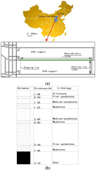
Figure 1.
Layout and roof lithology of the 8304 longwall working face: (a) Layout of the 8304 longwall working face; (b) Lithological profile.

Table 1.
Parameters of the roof layers.
The comprehensive mechanized coal mining method was adopted in the test longwall working face. The maximum daily face advance is 12.7 m/day, and the average is 8.3 m/day. To mine the coal seam, a line of hydraulic supports was used to support the longwall roof and to form a working space for mining. Within the working space, a shearer is used to cut the coal wall, and a scraper conveyor is used to carry the coal away from the longwall. There is an entry on both sides of the longwall with rectangular dimensions of 5.0 m × 3.1 m; the retained entry is used as a pedestrian and ventilation channel, and the not retained entry on the other side is used as the coal transport channel by the scraper conveyor. Related equipment and auxiliary devices are also placed in the not retained entry to assist in the coal mining and transport. Then, when mining the adjacent 8305 longwall working face, the retained entry is used as the coal transport channel. As the face of the longwall working face advances during the mining process, the goaf roof behind the longwall working face and hydraulic supports gradually collapses, and the gangue piles gradually accumulate and become compressed. At a certain distance behind the longwall working face, the gangue pile in the goaf becomes sufficiently dense to effectively support the overburden rock layers.
3. The Gob-Side Entry Retaining by Roof Cutting (GERRC) Technique
3.1. Technological Process
The core technique of GERRC is using bilateral cumulative tensile blasting to cut the retained entry roof along the advance direction of the longwall working face and to cut off the stress transmission between the entry roof and the gob roof. Meanwhile, a constant resistance and large deformation anchor cable is used to reinforce the retained entry roof and to control its deformation. In this way, the gob roof collapses along the cutting surface into gangue, and the caved gangue can effectively support the overlying strata after mining [15].
The sections orthogonal to the mining advance direction shown in Figure 2 show that the technological process of the GERRC technique can be divided into the following six steps: (a) Excavating the entry for two adjacent longwall working faces. (b) Carrying out support reinforcement on the entry roof. (c) Carrying out the entry roof cutting according to the design and field blasting tests. (d) Installing the advance temporary support on the entry roof in a certain area ahead of the longwall working face. (e) After the longwall mining, installing the temporary support behind the longwall working face and gangue wall maintaining support with metal nets, steel I-beam sfigureupports and single hydraulic props behind the longwall to prevent the gangue from collapsing into the retained entry and to ensure the stability of the entry roof. (f) When the goaf roof collapse completely and the rock surrounding the retained entry is stable, the gangue wall has the strong capacity to support the overburden rock, so the temporary support behind the longwall working face can be removed, and only the gangue wall maintaining support needs to be left until the reuse of the entry by the next longwall working face, and the entry is completely retained [21].
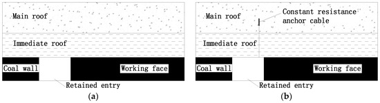
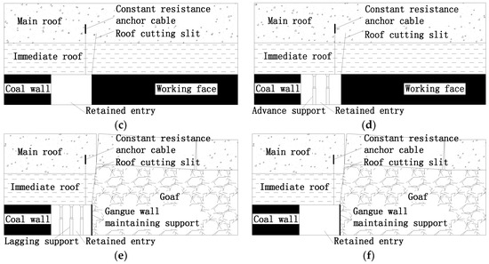
Figure 2.
Technological process of the gob-side entry retention by roof cutting (GERRC) technique: (a) Entry excavation; (b) Support reinforcement; (c) Roof cutting; (d) Advanced temporary support; (e) Temporary support behind the working face and gangue wall maintaining support; (f) Retained entry.
The above summarization demonstrates that, in the GERRC coal mining method, the first key step before longwall mining is roof cutting in the entry. At this time, the entry roof and overburden are supported by anchor cables and coal walls on both sides. One side is the main mining face, and the other side is the adjacent mining face that will be mined next. To avoid the influence of stress concentration during longwall advancement, temporary support is installed in a certain area in front of the longwall by using single props. With the advance of the longwall working face via mining, the goaf roof collapses, but the resulting gangue pile behind the longwall working face is not particularly dense at first. Under this condition, the gangue pile has a weak capacity to support the overburden, so temporary support behind the longwall working face should be installed. At this time, the entry roof and overburden are supported by anchor cables, the coal wall on one side (the next mining longwall) and temporary support. In addition, gangue wall maintaining support should also be applied to prevent the collapse of gangue into the entry. Finally, with the continued advance of the longwall working face, the goaf gangue becomes compressed beyond a certain distance from the longwall. Therefore, the goaf adjacent to the entry can be filled with the gangue collapsing and expanding from the gob roof after the longwall mining. In addition, with the mining advance of the longwall, the gangue in the goaf far from the longwall working face is compressed completely. At that point, the gangue is sufficiently dense to effectively support the overburden rocks. Then, the temporary support behind the longwall working face can be removed, and the entry roof and overburden are supported by anchor cables, the coal wall on one side (the next longwall mining face) and the compressed gangue wall.
3.2. Entry Retaining Design
3.2.1. Design of Roof Cutting
The key parameters of roof cutting should be determined first. Among these parameters, the roof cutting height is calculated as follows [24]:
where HF is the minimum roof cutting height; HM is the mining height; △H1 is the amount of roof subsidence; △H2 is the amount of bottom heave; and K is the bulking coefficient of the gob roof. In this study, the K is 1.41 according to geological testing of the roof rock. The mining height HM is 3.1 m. Neglecting the roof subsidence and floor heave, the minimum roof cutting height calculated with Equation (1) is 7.5 m. According to the roof lithologic histogram, the 6.92 m–7.72 m height range is mudstone. To cause the gob roof to collapse easily in the cutting range, the HF is finally designed to be 7.7 m. At the same time, as shown in Figure 3, the roof cutting angle is set to 15° to weaken the friction on the cutting surface when the goaf roof caves [22].
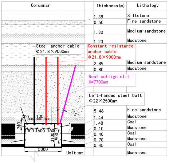
Figure 3.
Roof cutting and supporting design of the 8304 longwall working face tail gateway.
3.2.2. Design of Entry Support
In this entry retaining test, the supporting materials mainly include steel bolts, steel anchor cables, constant resistance anchor cables [27,28], and single hydraulic props. The specifications of the steel bolts are φ22 mm × 2500 mm, the installation anchorage force should be no less than 80 kN, and the pretightening force should be no less than 200 kN. The diameter of both the steel and constant resistance anchor cables is 21.8 mm, the lowest limit of anchorage force of the two types of anchor cables is 400 kN, and the lowest limit of the pre-tightening force is 250 kN. The single hydraulic prop model is DN35-160/90, its maximum supporting height is 3500 mm, the rated working resistance is 160 kN, and the initial supporting force is not less than 90 kN.
The constant resistance anchor cable is the key support reinforcing the roof. Its maximum allowable deformation is 350 mm, and the constant resistance value is 300 ± 20 kN. The schematic diagram is shown in Figure 4 [27], and the constitutive relation and energy model are shown in Figure 5 [28]. The constant resistance anchor cable can be regarded as an ideal model of elastic and plastic components. When the pull force is less than the constant resistance, the anchor cable is in the elastic stage:
where P is the anchor cable load, kg is the stiffness coefficient, and x is the amount of elastic extension.
P = kgx,
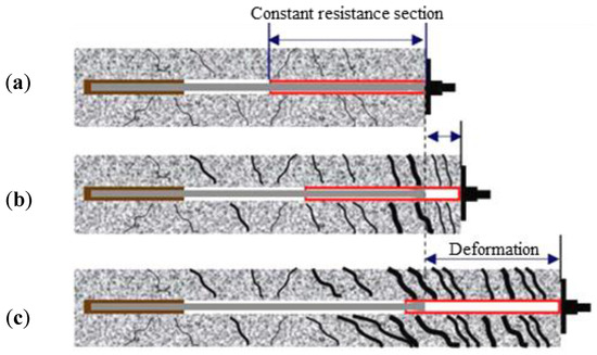
Figure 4.
Principle of the constant resistance anchor cable: (a) Before deformation of surrounding rock; (b) Under deformation of surrounding rock; (c) After deformation of surrounding rock.
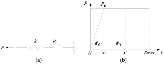
Figure 5.
Constitutive and energy models for the constant resistance anchor cable: (a) Constitutive relation; (b) Energy model.
When the pull force increases to the constant resistance stage, the anchor lock exhibits plastic slip. At this time:
where P0 is the constant resistance value.
P = P0,
Therefore, when plastic slip occurs, the energy absorbed by the constant resistance anchor cable can be calculated as:
where x0 is the maximum amount of elastic deformation and x’ is the total deformation amount.
Constant resistance anchor cables are generally 1–2 m longer than the roof cutting height, so the anchor cable length is designed to be 9 m in this study. According to the roof lithology shown in Table 1, the bolt-cable support section is shown in Figure 3. The entry roof features three anchor cables. The cables on the roof cutting side and in the middle of the roof surface are constant resistance anchor cables, and the one on the left on the roof uncut side is a steel anchor cable. The row spacing of anchor cables is 1500 mm on the roof cutting side and 3000 mm in the other two rows. In addition, according to the adjacent longwall working face field mining experience, the advance temporary support is designed as shown in Figure 6a: each support section is arranged with three hydraulic props, and the row spacing is 1 m. The temporary support behind the longwall is designed as shown in Figure 6b: each support section is arranged with five hydraulic props. Considering the roof cutting side is more prone to collapse, the row on the roof cutting side is designed with a spacing of 0.5 m, and the other four rows have a spacing of 1 m [26].
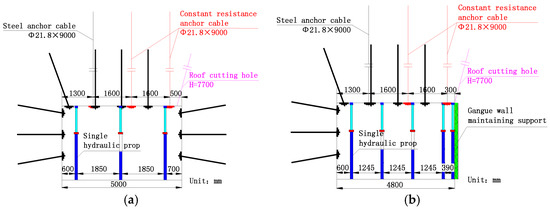
Figure 6.
Design of temporary support: (a) Temporary support in front of the longwall; (b) Temporary support behind the long wall.
The bolt-cable support is the key element of the retained entry support. Therefore, in order to form an effective anchoring zone in the entry roof, three kinds of anchoring drilling are used for steel bolts, steel anchor cables and constant resistance anchor cables in the GERRC coal mining method. For the steel bolts, the minimum depth requirement for the drilling is 2500 mm, the minimum diameter requirement for the drilling is 22 mm, and the drilling machine model used is a DCA-45. The first step of drilling is marking the installation position of the bolts in the roof, and then the anchor holes are drilled using the drilling machine. The length of the commonly used drill pipe is 1000 mm, and the drill pipes can be connected to meet the demand for different drilling depths. The drilling method for the steel anchor cables is similar to that of the steel bolts. The differences are that the minimum drilling depth requirement is 9000 mm, and the minimum drilling diameter requirement is 21.8 mm. For the constant resistance anchor cables, the drilling method is somewhat different. First, this method also requires drilling an anchor hole with the designed depth, diameter and position. The minimum requirements for drilling depth and diameter for constant resistance anchors are same as those for the steel anchor cables. However, the bottom section the drilling hole must be widened to provide the space necessary to install the constant resistance device. This section’s minimum length and diameter requirements are 350 mm and 90 mm. After the drilling of the anchor hole, the appropriate amount anchorage agent should be placed at the top of the hole. Then, the cable is inserted into the anchor hole and used to stir the anchorage agent adequately. After the cable top is anchored, the pre-tightening force and lock are applied to the bottom of the cable to form the effective anchoring zone. In this study, the used anchorage agent model is MSK2360. Every steel bolt anchor hole uses two strips, and every anchor cable anchor hole uses four strips. In this study, the top of the anchor cable is in the stable medium sandstone layer, which provides good anchor conditions.
4. Monitoring of Mine Pressure
The mine pressure monitoring system for the 8304 longwall working face contains two parts: the longwall working face and the gateway monitoring, as shown in Figure 7 [29]. In this system, the longwall working face monitoring is designed to monitor the working resistance of hydraulic supports in the longwall working face. The gateway monitoring can be divided into two categories: full entry monitoring and behind the longwall working face monitoring. Force monitoring of the constant resistance anchor cables and roof separation monitoring are classified as full entry monitoring. The pressure of the single props, the convergence between the roof and the floor and the lateral pressure of the gangue are classified as behind the longwall monitoring.
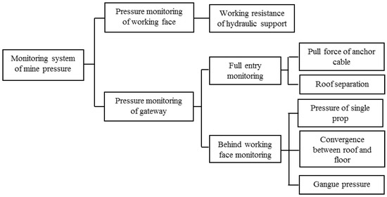
Figure 7.
Mine pressure monitoring system for GERRC.
4.1. Pressure Monitoring Design for the Longwall Working Face
The 8304 longwall working face mining and GER are conducted according to the above design, and wireless pressure sensors are arranged in the longwall working face to monitor the change in hydraulic support working resistance. The two longwall working face sides are subject intensive monitoring, so the monitoring equipment is installed in 6 hydraulic supports on two sides and 11 hydraulic supports in the center. The specific numbers of the hydraulic supports with installed sensors are 1, 6, 12, 23, 34, 45, 56, 62, 68, and 73. The longwall pressure monitoring layout is shown in Figure 8a, and the monitoring devices are shown in Figure 8b.
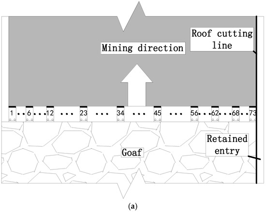
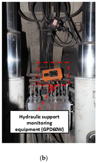
Figure 8.
Monitoring design of the 8304 longwall working face: (a) Monitoring scheme; (b) Monitoring equipment (GPD60W).
4.2. Gateway Pressure Monitoring Design
The plan view and cross section layouts of the gateway mine pressure monitoring are shown in Figure 9. The force monitoring layout spacing for the constant resistance anchor cable and roof separation monitoring is 50 m, and there are 10 monitoring points in the entry. The layout spacing of the single prop pressure monitoring, the convergence monitoring between the roof and the floor and the gangue pressure monitoring is 20 m, and there are 10 monitoring points, with mining advance, arranged in the entry behind the longwall working face. The monitoring equipment is shown in Figure 10.
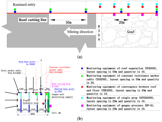
Figure 9.
Mine pressure monitoring scheme using GERRC: (a) Plan view layout; (b) Cross section layout.
Figure 10.
Monitoring equipment in GERRC: (a) Monitoring equipment for constant resistance anchor cable (YAD200) and roof separation (YUD300); (b) Monitoring equipment for single prop (GPUD2000) and convergence (YHU200); (c) Monitoring equipment for gangue pressure (DP-6).
4.3. Pressure Monitoring Results
4.3.1. Pressure Monitoring Results for the Longwall Working Face
All the longwall working face monitoring results are shown in Figure 11a. To analyze the effect of pressure released by roof cutting, as shown in Figure 11b–d, the monitoring data from three typical hydraulic supports arranged near the roof cutting side (#73 support), the middle of the longwall working face (#34 support) and far away from the roof cutting side (#1 support) are chosen for comparison.
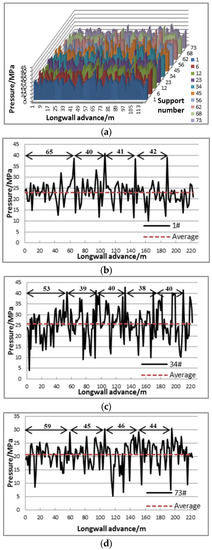
Figure 11.
Monitoring results of hydraulic supports at typical positions: (a) Overall pressure monitoring of supports; (b) #1 support (far from the roof cutting side); (c) #34 support (in the middle of the longwall working face); (d) #73 support (near the roof cutting side).
According to the monitoring results of pressure for three typical supports, the weighting step and strength are shown in Table 2. It can be seen that in the middle of the longwall working face, the pressure step is the shortest, and the pressure strength is the highest. The roof cable bolts have been unloaded within the range of 20 m next to the retained entry in the open off-cut; thus, compared with that of the uncut side, the first weighting step of the roof cutting side is shorter. Affected by the roof cutting and pressure release, the periodic weighting step on the entry retaining side is longer than that on the other sides. The average increase is 4 m. The periodic weighting strength is weaker. The average pressure is reduced by 2.1 MPa, and the peak pressure strength is reduced by 10.2 MPa. In summary, the effect of pressure from roof cutting is obvious.
Table 2.
Hydraulic support resistance statistic.
During the first 127 m of the longwall working face mining advance, according to the monitoring results of the 10 marked hydraulic supports, the first and periodic weighting steps of the roof, peak and the average support pressure strength are statistically analyzed. The results are shown in Figure 12. It can be seen that the longwall working face weighting step and strength distributions agree with the analysis results of the above three typical supports. Because of the effects of the roof cutting and some cable bolts unloaded in the open off-cut, the distributions are asymmetrical. The periodic weighting step of the roof cutting side is longer, and the periodic weighting strength of the roof cutting side is weaker, than that on the uncut side.
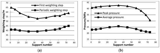
Figure 12.
Pressure statistics of hydraulic support in the longwall working face: (a) Weighting step; (b) Weighting strength.
In addition, the pressure release effect is relatively obvious in the range of the #56 to #73 supports; that is, the lateral area affected by roof cutting on the longwall working face at the retained entry side is approximately 29.75 m (the spacing between single hydraulic supports is 1.75 m), and the closer to the cutting slit, the more significant the effect is. In addition, the effect from roof cutting and released pressure on the support peak pressure is more intense than that on the average pressure. In particular, comparing the roof cutting side with roof uncut side of the 8304 longwall working face, the maximum pressure relief percentages of the peak pressure and the average pressure are 25.0% and 9.2%, respectively.
4.3.2. Gateway Pressure Monitoring Results
The gateway monitoring results are shown in Figure 13. The data record of the gangue pressure monitoring begins at a distance from the longwall working face of 29 m, and the initial value is 0.2 MPa. Then, the gangue pressure rises gradually, until it reaches the maximum value of 0.46 MPa at a distance from the longwall of 103 m. After that, the gangue pressure decreases as the longwall working face advances and stabilizes at 0.28 MPa at a longwall working face distance of 223 m. The pulling force of the constant resistance anchor cable on the roof cutting side also exhibits an initial increase followed by a decrease and finally stabilization. The anchor cable pulling force begins to rise when the longwall working face advances 19 m and reaches a constant resistance at a longwall working face distance of 3 m. Then, the force declines at a longwall distance of 25 m and becomes stable at 112 m after a slight rise. In the field, the lock retraction of the constant resistance anchor cable can be clearly observed in the retained entry (as shown in Figure 14), and the average retraction is approximately 37 mm. The roof separation and the convergence between the roof and the floor exhibit the same pattern and respectively stabilize at 99.2 mm and 298.8 mm at a longwall distance of 218 m. The hydraulic support is 8 m, so the single props are installed at a longwall distance of 8 m. When the single prop on the roof cutting side is 18 m from the longwall working face, the working resistance reaches the peak value of 29.6 MPa, and the fluid leaking phenomenon begins to appear. Up to a longwall distance of 214 m, the pressure value tends to be stable at approximately 29 MPa.
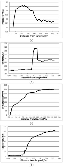
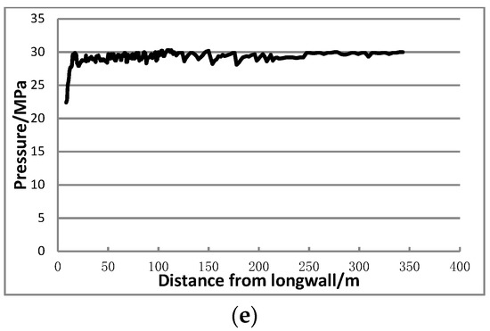
Figure 13.
Entrance monitoring results (the abscissa values smaller than zero are positions ahead of the longwall face): (a) Gangue pressure; (b) Pull force of anchor cable; (c) Convergence between roof and floor; (d) Roof separation; (e) Working resistance of a single prop.
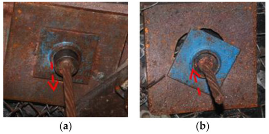
Figure 14.
Constant resistance anchorage lock energy absorption: (a) Before anchor lock plastic slip; (b) After anchor lock plastic slip.
The monitoring data show that the effect of pressure release by roof cutting is obvious. When the retained entry is more than 223 m from the longwall working face, the gangue wall reaches a steady state. In regard to the constant resistance anchor cable, the pull force curve becomes relatively smooth at a distance from the longwall of more than 112 m. In addition, the convergence between the roof and the floor and the working resistance of a single prop also stabilize at distances of 218 m and 214 m, respectively, from the longwall. Therefore, the whole retained entry enters a stable state when it is more than 230 m behind the mining longwall working face. Then, the single props temporarily supporting the entry behind the longwall working face can be removed, and only the gangue wall support is maintained. Field photographs are shown in Figure 15. After removing the single props, the roof separation and convergence between the roof and the floor all present a slight increase. Finally, the roof separation becomes stable at 103.7 mm, the convergence becomes stable at 303.4 mm, and the average height of the retained entry is 2796.6 mm. The section size of the retained entry can meet reuse demand.
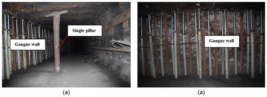
Figure 15.
Field entry retaining effects: (a) Section of retained entry; (b) Gangue wall.
5. Mechanism of Overlying Strata Pressure
To further analyze the characteristics of overlying strata pressure and to explore the mechanism of pressure appearance under roof cutting conditions, in this section, theoretical calculation is used to analyze the key roof structure and roof weighting parameters. The retained entry is usually very long, and the stress states of the entry-surrounding rocks vary regionally, so the relative analyses can be simplified to two-dimensional plane problems along the direction orthogonal to the mining advance direction through the division of different stress regions. In addition, in typical material mechanics and elastic mechanics, there are some classical assumptions, such as the continuity hypothesis, homogeneity hypothesis, and small deformation hypothesis. Based on these assumptions, many problems in related fields can be effectively solved by mathematical methods. Similarly, taking these methods as references and assuming some typical conditions, rock mechanics can also exploit these classical assumptions to solve some field and engineering problems. In this paper, the retained entry roof in different stages is supported well by various support types, such as bolts and cables, coal walls, gangue walls, and gangue wall maintaining support. Therefore, the system can be regarded as a deformable body within a certain deformation range [30,31,32,33,34,35,36,37,38].
5.1. Mechanism of Longwall Working Face Pressure
5.1.1. Analysis of Roof Structure
During the mining process, when the direct roof has broken but has not collapsed, its weight is entirely supported by the longwall working face hydraulic supports. Therefore, the direct roof thickness MZ can be calculated based on the hydraulic support working resistance before periodic weighting. The calculation formula is as follows [30]:
where is the direct roof pressure due to gravity, MPa; is the thickness of each direct roof layer, m; is the direct roof density, kN/m3; is the direct roof suspension coefficient; and n is the number of direct roof layers.
According to the monitored results in Figure 13, in the area unaffected by roof cutting, the average support working resistance before roof periodic weighting is 5316 kN (24.1 MPa), and the average peak working resistance during roof weighting is 9175 kN (41.6 MPa). The periodic weighting strength is high. In the area affected by roof cutting, the average support working resistance before periodic weighting is 4720 kN (21.4 MPa), and the average peak working resistance with roof weighting is 7361 kN (34.6 MPa). The periodic weighting strength is low. The relevant roof parameters are shown in Table 1, and the suspension coefficient can be calculated using Equations (7) and (8) [31]:
where S0 is the distance between the support resultant force point and the coal wall, where S0 = 0.5 LK in the general fully mechanized hydraulic support condition; LK is the roof control distance, m; LS is the roof hanging length, m; and l is the length of the roof breaking step, LS = l − LK. Under the uncut roof condition, the breaking step length of each direct roof layer can be obtained using Equation (9):
where LOZ is the length of a single layer breaking step, m, and [σ] is the rock tensile strength, MPa. According to field experience, LOZ is 0.5 times as long as the calculated value under the roof cutting condition. In addition, the calculated results for each layer are shown in Table 3.
Table 3.
Inverse calculation of direct roof thickness.
Comparing the inverse calculation results of each layer with the monitored results, it can be seen that in the area unaffected by roof cutting, the direct roof is composed of a lower mudstone layer and part of a fine sandstone layer (484 kN ≤ 5316 kN ≤ 16352 kN) and that in the area affected by roof cutting, the direct roof is composed of a lower mudstone layer, a fine sandstone layer, an upper mudstone layer and part of a medium sandstone layer (4126 kN ≤ 4720 kN ≤ 5404 kN). Therefore, some lower basic roof strata turn into the direct roof after the roof cutting, and the direct roof thickness increases following the roof cutting. Consequently, the structural change after roof cutting is mainly reflected in the following points: (1) The direct roof thickness of the affected zone increases, and the maximum thickness is greater than the cutting height. (2) The suspension plate length of the direct roof behind the longwall decreases in the affected zone, and the working resistance before periodic weighting of the hydraulic support decreases. (3) Due to the increase in the thickness of the direct roof, the gangue pile height in the goaf formed by the collapsed direct roof also increases correspondingly. Subsequently, the breaking angle of the basic roof is smaller, the basic roof suspension plate is longer, the periodic weighting step increases, and the periodic weighting strength decreases.
5.1.2. Analysis of Weighting Characteristics
Based on the cantilever beam structure of the roof during fully mechanized mining of the face and the overlying strata weighting mechanism, the periodic weighting step and strength of the basic roof can be calculated as follows [32]:
where Rt is the tensile strength of the basic roof rocks, MPa; h is the thickness of the basic roof, m; q is the basic roof load, MPa; F is the force of hydraulic support when roof weighting, kN; φ is the frictional angle between rock blocks, °; θ is the breaking angle of the rock, °; s is the subsidence of key layers, m; b is the support width, m; k1 is the correction factor of the weighting step; and k2 is the weighting strength correction factor.
According to the monitoring results shown in Table 2 and the above calculation results for the direct roof thickness assuming θ and K values of 45° and 1.41, respectively, and putting the related 8304 longwall working face roof parameters into Equations (10) and (11), the results are as follows: k1 = 1.08, k2 = 1.07 (on the roof uncut side); k1 = 1.03, k2 = 1.03 (in the middle of the longwall working face); and k1 = 0.98, k2 = 0.92 (on the roof cutting side). Although the roof structure and pressure characteristics change after roof cutting, the pressure mechanism is still based on the cantilever beam structure. The weighting step and strength can still be calculated using the formulas applied in the traditional mechanized longwall technique. The relevant correction factors are all in the range of [0.9–1.1].
5.2. Mechanism of Gateroad Pressure
The technological process of the GERRC technique is divided into six steps, as shown in Figure 2. The implementation of one step may influence another working procedure, as shown in Figure 16 [33]. (1) To avoid the influence of roof split blasting on entry reinforcement support and the advance temporary support, an appropriate safety distances should be established among entry reinforce supports, roof cutting blasting and advance temporary supports. The safety distance is set to 20 m in the field; namely, L① − L② ≥ 20 m, and L② − L③ − L⑤ ≥ 20 m. (2) To avoid stress concentration damage to the entry in advance of the longwall working face, an advance temporary support zone with a usual length of 30–40 m should be set up in advance of the longwall working face; namely, L③ = 30–40 m. (3) The temporary support behind the longwall and the gangue wall maintaining support should be established at the appropriate times behind the longwall working face. The gangue wall maintaining support should be preserved until the retained entry is completely abandoned after reuse, and the temporary support can be removed when the retained entry is stable. In general, the retained entry tends to be stable when it is approximately 200 m behind the longwall working face; namely, L④ ≈ 200 m. According to the 8304 longwall working face pressure monitoring results, L③ = 30 m, and L④ = 230 m.
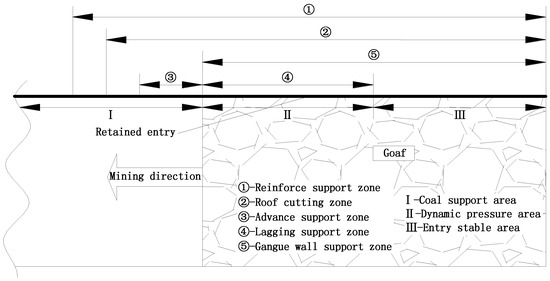
Figure 16.
Process zoning map of GERRC in the 8304 longwall working face retained entry.
Based on the relationships among each entry retaining process in time and space with the longwall working face mining advance summarized above, the retained entry can be divided into three areas: coal support, dynamic pressure and stable entry areas (areas I, II and III, respectively, as shown in Figure 16, according to different surrounding rock structures. The coal support area is the entry segment of the entry in front of the longwall working face, as shown in Figure 2a–d. At this time, the coal walls on the two sides of the entry support the overlying strata, and the entry stress state can be divided into three states—the advance, reinforcement and original support stress states —along the mining advance direction of the longwall working face. The dynamic pressure area is the entrance segment behind the longwall working face that is not stable, shown in Figure 2e. In this segment, the gangue and coal walls on each side of the retained entry support the overlying strata, and the gangue wall has not stabilized, so the retained entry still bears the dynamic pressure from overlying strata. The stable entry area is the segment behind the longwall working face that has stabilized, shown in Figure 2f. The overlying strata are supported by the gangue and coal walls on the two sides of the retained entry in this segment, but unlike the dynamic pressure area, the gangue wall is stable at this time. In other words, the gangue wall has been compacted and basically bears no obvious dynamic pressure.
5.2.1. Coal Support Area
The simplified mechanical entry model in the coal support area is shown in Figure 17, and the coal walls on the two sides of the entry support the overlying strata. In Figure 17, q0 is the average direct roof weight load; F1 is the resultant force of all supports in the entry; a is the width of the entry; and b is the distance between F1 and the coal wall far from the longwall working face [34,35,36]. According to the X-Y coordinates in Figure 17 and consideration of the entry roof as a mechanical model of a simple supported beam, its deflection curve equation is as follows:
where EI is the beam bending stiffness. The term y achieves the maximum deflection when x = a/2, and its absolute value is:
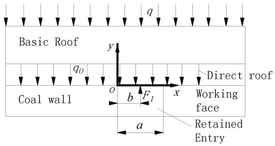
Figure 17.
Simplified mechanical model of the coal support area.
The roof support in this area is mainly realized by anchor cable. According to the theory of suspension, the supporting force F1 in the entry can be calculated using Equation (14):
According to Equation (12), in this area, the deformation in the middle of the entry roof is the largest, so the support in the entry should be concentrated in the middle. At the same time, the surrounding rock stress states in this area can be divided into three states: the advance, reinforcement and original support stress states. The roof stress structures of the three states are the same and are basically unaffected by roof cutting. Therefore, the design of anchor cable support strength can be calculated via Equation (14). However, in the advance support stress state, the high stress concentration with advance of the longwall working face should also be considered; thus, advance temporary support with single hydraulic props should be set up at the appropriate time.
5.2.2. Dynamic Pressure Area
A simplified mechanical model of the entry in the dynamic pressure area is shown in Figure 18. The gangue and coal walls on each side of the retained entry support the overlying strata, and the gangue wall is not stable at this time. In Figure 18, TA is the horizontal thrust of rock A; NA is the shear force of rock A; MA is the bending moment of rock A at point A’; TB, NB and MB have the corresponding meanings as TA, NA and MA, respectively, but for rock B; M0 is the direct roof limit bending moment; x0 is the lateral width of the limit equilibrium area in the coal wall; σ is the coal wall plastic zone support; and F2 is the gangue wall support. In this area, F2 is small due to gangue wall instability. In fact, F2 is approximately 0 in a certain area close to the longwall working face. Based on this and the X-Y coordinates in Figure 17, the entry roof can be regarded as a cantilever beam mechanical model, and the deflection curve equation is given below:
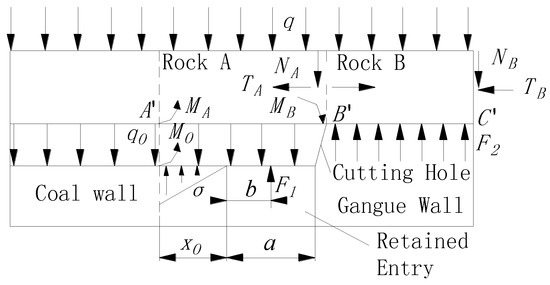
Figure 18.
Simplified mechanical model of dynamic pressure and stable entry areas.
The term y reaches the maximum deflection when x = a, and its absolute value is:
The roof support in this area is mainly realized by single hydraulic props. To determine F1, x0 and σ should first be obtained [37]:
where c’ and φ are the cohesive force and internal friction angle, respectively, of the interface between the coal seam and the roof; m is the coal seam thickness; ka is the lateral pressure coefficient; k is the maximum stress concentration coefficient; H is mining depth; and px is the coal wall support strength.
The stress states of rocks A and B are analyzed by the static equilibrium method:
Rock B: , then , then
Rock A: then:
TA can be calculated via Equations (22) and (23):
where L is the lateral breaking span of the basic roof; △SA is the subsidence of rock A at point B’; and △SB is the subsidence of rock B at point C’. F1 is determined as follows:
According to Equation (15), in this area, the deformation on the roof cutting side of the entry roof is the largest, so the support in the entry should be more concentrated there. In addition, the roof support in this area is mainly realized by anchor cable support and the temporary support of single hydraulic props. The anchor cable support strength can still be calculated using Equation (14). At the beginning of this area, F2 is approximately 0 in a certain area close to the longwall working face, so F1 can be solved using Equation (24).
5.2.3. Stable Entry Area
The simplified mechanical model of the entry in the stable entry area is also shown in Figure 18. However, unlike the dynamic pressure area, the gangue wall is stable in this area, and F2 increases sharply. In addition, when the rock surrounding the retained entry is stable, the temporary support can be removed, leaving only the gangue wall maintaining support; then, F1 decreases. The retained entry in this area is stable under various support types, such as bolt-cable, gangue wall and gangue wall maintaining supports. Thus, the roof can be regarded as a deformable body accumulating a certain degree of elastic energy, and its subsidence can be solved according to the energy principle and variation method [38]. The simplified mechanical model of the direct roof in this area is built as shown in Figure 19 based on the X-Y coordinates in Figure 17. The left boundary is fixed; the right boundary experiences pressure Pz3; the upper boundary exhibits a certain degree of deformation; the lower boundary experiences support Pz1 of the anchor cables and Pz2 of the gangue wall maintaining support; θ is the basic roof rotation; and c is the distance of Pz2 to the coal wall. The strain energy can be calculated using Equation (25):
where dV is an elastic element; and σ and ε are the stress and strain, respectively, of an elastic body. The direct roof deformation of the retained entry can be regarded as a plane strain problem, so the strain energy can be expressed by the displacement component:
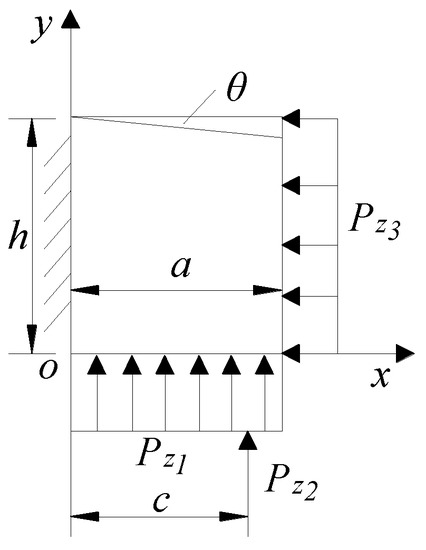
Figure 19.
Simplified mechanical model of the entry direct roof.
Assuming that the direct roof elastic body becomes stable after a slight deformation caused by external force, the Lagrange displacement variation equation can be obtained as follows:
where u and v are the displacement components; X and Y are the components of bulk force; and and are the components of surface force.
According to the retained entrance boundary conditions, the displacement component along the Y axis can be expressed as follows:
where E is the modulus of elasticity and μ is the Poisson ratio. Analyzing the stress states of rocks A and B based on the static equilibrium method under this condition, F1 is obtained as follows:
The temporary support behind the longwall has been removed in the stable entry area and the gangue wall maintaining support remains, so F1 = Pz2. Then, Equation (29) reveals that the greater the gangue wall support is, the smaller the demand on the entry support; in other words, the vertical pressure on the gangue wall maintaining support is smaller. Furthermore, according to Equation (28), when the vertical pressure on the gangue wall maintaining support is small, the roof vertical deformation is also small. Therefore, the support capacity of the gangue wall directly affects the support demand of the entry. When F1, calculated using Equation (29), is larger than the limit vertical support capacity of the gangue wall maintaining support, the temporary support cannot be removed completely, and some of it should remain to reinforce the vertical support capacity of the gangue wall maintaining support in order to achieve the condition Pz2 = F1.
According to analysis of the entry retaining mining pressure mechanism, the dynamic pressure area is the key part of the entry support in the whole entry retaining process, and in that area, the deformation of the entry roof is the largest, and the mine pressure is also the most intense. This explains why the related entry monitoring data changes rapidly within a certain distance from the longwall in the field monitoring results. Therefore, the support design of the dynamic pressure area should be paid more attention in the further promotion and application of the GERRC technique. In this section, the deformation characteristics and support requirements of the entry under different surrounding rock conditions are obtained. The results can provide a reference for the optimization of support design in the promotion of the GERRC technique.
6. Conclusions
First, this study summarizes the process of the GERRC technique and presents the entry retaining design for the 8304 longwall working face of the Tashan coal mine under conditions involving a medium-thick coal seam and a compound roof.
The longwall working face and gateroad mine pressures were monitored in the field, and variation patterns were obtained and analyzed. The main conclusions in terms of mine pressure behavior are as follows: (1) Affected by the roof cutting, the periodic weighting step on the entry retaining side is longer than that on the other side, and the average increase is appropriately 4 m. The periodic weighting strength becomes weaker, the average pressure is reduced by 2.1 MPa, and the peak pressure strength is reduced by 10.2 MPa after roof cutting. (2) The distributions of the weighting step and strength along the longwall working face are asymmetrical. The lateral distance affected by roof cutting is approximately 29.75 m from the longwall working face, and the closer to the cutting slit, the more significant the effects are. (3) The whole retained entry becomes stable when it is more than 230 m from the longwall working face, and then the single prop temporary supports in the stable entry area can be removed. The roof separation becomes stable at 103.7 mm, the convergence becomes stable at 303.4 mm, and the average entry retaining height is 2796.6 mm. The section size of the retained entry can easily meet the reuse demand of the next mining panel.
Finally, the mechanism of overlying strata pressure under the roof cutting condition was analyzed, and the main conclusions are as follows: (1) Within the area affected by roof cutting, the thickness of the immediate roof increases, and the suspension plate length behind the longwall working face decreases. Then, the hydraulic support working resistance before periodic weighting and the rotational breaking angle of the main roof decrease, thereby increasing the periodic weighting step and decreasing the periodic weighting strength. (2) Although the roof structure and pressure characteristics have changed after roof cutting, the pressure mechanism can still be explained using the cantilever beam theory. (3) The retained entry is divided into coal support, dynamic pressure and stable entry areas based on the surrounding rock state, and the formulas for the roof support requirements in these three different areas are obtained.
Author Contributions
All the authors contributed to this paper. M.H. and Y.G conceived and designed the research. X.M. and Y.G. performed the theoretical analysis and field tests. J.W. provided theoretical guidance in the research process. D.Z. and Y.L. analyzed the data.
Funding
This research was funded by the National Nature Science Foundation of China grant number No. 51574248, and the State Key Program of National Nature Science Foundation of China grant number No. 51134005.
Conflicts of Interest
The authors declare no conflict of interest.
References
- Torres-Fuchslocher, C. Understanding the development of technology-intensive suppliers in resource-based developing economies. Res. Policy 2010, 39, 268–277. [Google Scholar] [CrossRef]
- Löschel, A. Technological change in economic models of environmental policy: A survey. Ecol. Econ. 2002, 43, 105–126. [Google Scholar] [CrossRef]
- Cristóbal, J.; Guillén-Gosálbez, G.; Jiménez, L.; Irabien, A. Optimization of global and local pollution control in electricity production from coal burning. Appl. Energy 2012, 92, 369–378. [Google Scholar]
- Zhou, N.; Levine, M.D.; Price, L. Overview of current energy-efficiency policies in China. Energy Policy 2010, 38, 6439–6452. [Google Scholar] [CrossRef]
- Tokimatsu, K.; Konishi, S.; Ishihara, K.; Tezuka, T.; Yasuoka, R.; Nishio, M. Role of innovative technologies under the global zero emissions scenarios. Appl. Energy 2016, 162, 1483–1493. [Google Scholar] [CrossRef]
- Ameri, M.; Mokhtari, H.; Sani, M.M. 4E analyses and multi-objective optimization of different fuels application for a large combined cycle power plant. Energy 2018, 156, 371–386. [Google Scholar] [CrossRef]
- Milici, R.C.; Flores, R.M.; Stricker, G.D. Coal resources, reserves and peak coal production in the United States. Int. J. Coal Geol. 2013, 113, 109–115. [Google Scholar] [CrossRef]
- Xue, Y. From tradition to modern times: evolution of coal mining technology in China. J. Hubei Polytech. Univ. (Humanit. Soc. Sci.) 2013, 30, 7–15. [Google Scholar]
- Jiao, H.B.; Zhao, A.G. The present situation of longwall mining technology in China and its application in thick coal seam. J. North China Inst. Sci. Technol. 2004, 5, 34–37. [Google Scholar]
- He, M.C.; Xie, H.P.; Peng, S.P.; Jiang, Y.D. Study on rock mechanics in deep mining engineering. Chin. J. Rock Mech. Eng. 2005, 24, 2803–2813. [Google Scholar]
- Kang, H.P.; Niu, D.L.; Zhang, Z.; Lin, J.; Li, Z.H.; Fan, M.J. Deformation characteristics of supporting rock and supporting technology of gob-side entry retaining in deep coal mine. Chin. J. Rock Mech. Eng. 2010, 29, 1977–1987. [Google Scholar]
- Suchowerska, A.M.; Merifield, R.S.; Carter, J.P. Vertical stress changes in multi-seam mining under supercritical longwall panels. Int. J. Rock Mech. Min. Sci. 2013, 61, 306–320. [Google Scholar] [CrossRef]
- Wang, J.G.; Wang, G. Discussion on gateway retained along goaf technology with roof breaking and pressure releasing. Coal Eng. 2012, 58, 24–26. (In Chinese) [Google Scholar]
- Howladar, M.F.; Karim, M.M. The selection of backfill materials for Barapukuria underground coal mine, Dinajpur, Bangladesh: Insight from the assessments of engineering properties of some selective materials. Environ. Earth Sci. 2015, 73, 6153–6165. [Google Scholar] [CrossRef]
- He, M.C.; Song, Z.Q.; Wang, A.; Yang, H.H.; Qi, H.G.; Guo, Z.G. Theory of longwall mining by using roof cutting shortwall team and 110 method—The third mining science and technology reform. Coal Sci. Technol. Mag. 2017, 37, 1–9. [Google Scholar]
- He, M.C.; Gao, Y.B.; Yang, J.; Gong, W.L. An innovative approach for gob-side entry retaining in thick coal seam longwall mining. Energies 2017, 10, 1785. [Google Scholar] [CrossRef]
- Qian, M.G.; Miao, X.X.; Xu, J.L. Theoretical study of key stratum in ground control. J. China Coal Soc. 1996, 21, 225–230. [Google Scholar]
- Song, Z.Q. The basic law of the overlying strata movement on the stope. J. Shandong Min. Inst. 1979, 1, 64–77. [Google Scholar]
- Jia, X.R.; Zhai, Y.D. A summary of theory and practice of sheet metal pressure in stope. Gr. Pressure Strata Control 1999, 15, 22–25. [Google Scholar]
- Zhao, G.J.; Qian, M.G. Behavior of overlying hard strata above working and its effect on roof pressure. J. China Coal Soc. 1987, 3, 1–8. [Google Scholar]
- Sun, X.M.; Liu, X.; Liang, G.F.; Wang, D.; Jiang, Y.L. Key Parameters of gob-side entry retaining formed by roof cut and pressure releasing in thin coal seams. Chin. J. Rock Mech. Eng. 2014, 33, 1449–1456. [Google Scholar]
- Gao, Y.B.; Guo, Z.B.; Yang, J.; Wang, J.W.; Wang, Y.J. Steady analysis of gob-side entry retaining formed by roof fracturing and control techniques by optimizing mine pressure. J. China Coal Soc. 2017, 42, 1672–1681. [Google Scholar]
- Guo, P.F.; Zhang, G.F.; Tao, Z.G. Blasting technology of gateway retaining along goaf pressure release by roof cutting in hard and weak complex roof. Coal Sci. Technol. 2016, 44, 120–124. (In Chinese) [Google Scholar]
- Song, L.B. Study on roof cutting, pressure released and gateway driving technology in Shendong Mining Area. Coal Sci. Technol. 2016, 44, 80–85. (In Chinese) [Google Scholar]
- Wang, Y.J.; Gao, Y.B.; Wang, E.Y.; He, M.C.; Yang, J. Roof deformation characteristics and preventive techniques using a novel non-pillar mining method of gob-side entry retaining by roof cutting. Energies 2018, 11, 627. [Google Scholar] [CrossRef]
- Ma, X.G.; He, M.C.; Wang, J.; Zhu, X.Q.; Li, C.L.; Zhang, J.B.; Jiang, Q.Q. Study on design of chamber supporting behind cutting hole under condition of gob-side entry retaining in 8304 face of Yanya coal mine. Coal Technol. 2017, 36, 30–33. [Google Scholar]
- He, M.C.; Guo, Z.B. Mechanical property and engineering application of anchor bolt with constant resistance and large deformation. Chin. J. Rock Mech. Eng. 2014, 33, 1297–1308. [Google Scholar]
- He, M.C.; Li, C.; Gong, W.L.; Wang, J.; Tao, Z.G. Support principles of NPR bolts/cables and control techniques of large deformation. Chin. J. Rock Mech. Eng. 2016, 35, 1513–1529. [Google Scholar]
- Zhao, Y.M.; Zhang, N.; Si, G.Y. A fiber bragg grating-based monitoring system for roof safety control in underground coal mining. Sensors 2016, 16, 1759. [Google Scholar] [CrossRef] [PubMed]
- Yang, K.; Kong, X.Y.; Lu, W.; Liu, S. Study of strata pressure behaviors with longwall mining in large inclination and thick coal seam under closed distance mined gob. Chin. J. Rock Mech. Eng. 2015, 34, 4278–4285. (In Chinese) [Google Scholar]
- Tan, Y.L. Mining Pressure and Strata Control; Coal Industry Press: Beijing, China, 2008. [Google Scholar]
- Li, H.M.; Jiang, D.J.; Li, D.Y. Analysis of ground pressure and roof movement in fully-mechanized top coal caving with large mining height in ultra-thick seam. J. China Coal Soc. 2014, 39, 1956–1960. (In Chinese) [Google Scholar]
- Chi, B.S.; Zhou, K.F.; He, M.C.; Yang, J.; Wang, Q.; Ma, X.G. Optimization research on supporting parameters of roof cutting entry retaining with large mining height face. Coal Sci. Technol. 2017, 45, 128–133. [Google Scholar]
- Xu, Y.; Zhou, H.; Bai, J.B.; Chen, J. Characteristics and control method of floor heave in gob-side entry retaining. Chin. J. Rock Mech. Eng. 2015, 34, 4235–4243. [Google Scholar]
- Gao, Y.B.; Liu, D.Q.; Zhang, X.Y.; He, M.C. Analysis and optimization of entry stability in underground longwall mining. Sustainability 2017, 9, 2079. [Google Scholar] [CrossRef]
- Shehpari, M. A review of underground mine backfilling methods with emphasis on cemented paste backfill. J. Geotech. Geoenviron. Eng. 2015, 20, 5183–5208. [Google Scholar]
- Hou, C.J.; Ma, N.J. Stress in in-seam roadway sides and limit equilibrium zone. J. China Coal Soc. 1989, 4, 21–29. [Google Scholar]
- Yang, H.B.; Wang, Z.G.; Zhao, Y.H.; Song, X.C. Study on roof control technology for withdrawal passageway in fully mechanized coal face with large mining height. Min. Saf. Environ. Prot. 2014, 10, 59–61. (In Chinese) [Google Scholar]
© 2018 by the authors. Licensee MDPI, Basel, Switzerland. This article is an open access article distributed under the terms and conditions of the Creative Commons Attribution (CC BY) license (http://creativecommons.org/licenses/by/4.0/).